ASP-MG24TDB - Hi-Fi System Atlas Sound - Free user manual and instructions
Find the device manual for free ASP-MG24TDB Atlas Sound in PDF.


| Product Type | DSP Controller 2x4 Speaker Processor / Masking Generator |
| Brand | Atlas Sound (AtlasIED) |
| Model | ASP-MG24TDB |
| Dimensions (Unit) | 19" x 1.75" x 8" (483mm x 44mm x 203mm) |
| Dimensions (Shipping) | 24.75" x 3.15" x 14.15" (628mm x 80mm x 359mm) |
| Weight (Unit) | 7 lb (3.2 kg) |
| Weight (Shipping) | 10 lb (4.5 kg) |
| Power Supply | External UL rated 90-240VAC, 20W, DC power supply |
| Inputs | 2 selectable Mic/Line inputs (3-pin balanced Phoenix) |
| Outputs | 4 balanced outputs (3-pin Phoenix) |
| Masking Generators | 4 independent white/pink noise generators |
| Processing | 32-bit (40-bit extended) floating point DSP, 96kHz sampling rate |
| Analog Converters | High performance 24-bit |
| Frequency Response | 20Hz - 20kHz (+/- 0.1dB) |
| Dynamic Range | 115dB (unweighted) |
| Total Harmonic Distortion | 0.02% (1kHz @ +4dBu) |
| Control Interfaces | RS-232, USB, RJ45 (Ethernet for TDB version) |
| Program Storage | 14 user programs in non-volatile memory |
| Warranty | 3 years (electronics and control systems) |
| Cleaning Instructions | Use only dry cloth; do not block ventilation openings |
| Safety | Grounding type plug required; avoid water and moisture; refer servicing to qualified personnel |
| Spare Parts & Repairability | Contact AtlasIED for service and replacement parts; only use provided power supply |
Frequently Asked Questions - ASP-MG24TDB Atlas Sound
User questions about ASP-MG24TDB Atlas Sound
0 question about this device. Answer the ones you know or ask your own.
Ask a new question about this device
Download the instructions for your Hi-Fi System in PDF format for free! Find your manual ASP-MG24TDB - Atlas Sound and take your electronic device back in hand. On this page are published all the documents necessary for the use of your device. ASP-MG24TDB by Atlas Sound.
USER MANUAL ASP-MG24TDB Atlas Sound
ASP-MG24 / ASP-MG24TDB
Signal Processor / Masking Generator 2 Input x 4 Output


ASP-MG24
Owner's Manual
Table of Contents
Important Safety Instructions.... 3
Introduction 5
Key Features.... 5
Front Panel Description....6
Rear Panel Description....7
Getting to Know the Software....8
Mic / Line Input 9
Masking Generator Inputs....13
Masking Generator Outputs....16
File Import and Export....21
Specifications 26
Warranty 32
ASP-MG24
Owner's Manual
Important Safety Instructions
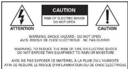

The lightning flash with arrowhead symbol within an equilateral triangle, is intended to alert the user to the presence of uninsulated "dangerous voltage" within the product's enclosure that may be of sufficient magnitude to constitute a risk of electric shock to persons.
The exclamation point within an equilateral triangle is intended to alert the user to the presence of important operating and maintenance (servicing) instructions in the literature accompanying the product.
- Read these instructions.
- Keep these instructions.
- Heed all warnings.
- Follow all instructions.
- Do not use this device near water.
- Clean only with dry cloth.
- Do not block any ventilation openings. Install in accordance with the manufacturer's instructions.
- Do not install near any heat sources such as radiators, heat registers, stoves, or other devices that produce heat.
- Do not defeat the safety purpose of the polarized or grounding-type plug. A polarized plug has two blades with one wider than the other. A grounding type plug has two blades and a third grounding prong. The wide blade or the third prong are provided for your safety. If the provided plug does not fit into your outlet, consult an electrician for replacement of the obsolete outlet.
- Protect the power cord from being walked on or pinched particularly at plugs, convenience receptacles, and the point where they exit from the device.
- Only use attachments / accessories specified by the manufacturer.
- Use only with the cart, stand, tripod, bracket, or table specified by the manufacturer, or sold with the device. When a cart is used, use caution when moving the cart / device combination to avoid injury from tip-over.

- This product is equipped with a three-wire grounding-type plug, a plug having a third (grounding) pin. This plug will only fit into a grounding-type power outlet. This is a safety feature. If you are unable to insert the plug into the outlet, contact your electrician to replace your obsolete outlet. Do not defeat the safety purpose of the grounding-type plug.
- Unplug this device during lightning storms or when unused for long periods of time.
- Refer all servicing to qualified service personnel. Servicing is required when the device has been damaged in any way, such as power-supply cord or plug is damaged, liquid has been spilled, or objects have fallen into the device, the device has been exposed to rain or moisture, does not operate normally, or has been dropped.
- WARNING: To reduce the risk of fire or electric shock, this device should not be exposed to rain or moisture and objects filled with liquids, such as a vase, should not be placed on this device.
- To completely disconnect this equipment from the mains, disconnect the power supply cord plug from the receptacle.
- The mains plug of the power supply cord shall remain readily operable.
- Protective earthing terminal. The apparatus should be connected to a mains socket with a protective earthing connection.
ASP-MG24
Owner's Manual

NING - When The Device Is In Use
- WARNING: The terminals marked with symbol of 7 may be of sufficient magnitude to constitute a risk of electric shock. The external wiring connected to the terminals requires installation by an instructed person or the used of ready-made leads or cords.
- WARNING: The apparatus shall not be exposed to dripping or splashing and that objects filled with liquids, such as vases, shall not be placed on apparatus.
- WARNING: The mains plug is used as disconnect device, the disconnect device shall remain readily operable.
• To prevent electric shock, do not remove the product cover as there are high voltage components inside. Refer all servicing to AtlasLED. -
Should any of the following irregularities occur during use, immediately switch off the power, disconnect the power cord from the AC outlet and contact AtlasLED. Do not to attempt to continue operation with the product as this may cause fire or electric shock:
-
Smoke or strange smell coming from the unit.
- If the product falls or the case is damaged.
- If water or any metallic objects falls into the product.
• If the power supply cord is damaged in any way. - If the unit is malfunctioning.
- Do not insert or drop metallic objects or flammable materials into the ventilation holes of the product's cover, as this may result in electric shock or fire.
• Do not place any containers with liquid or metallic objects on the top of the product. If any liquid spills into the unit, fire or electric shock may result. - Never operate this product or touch the power supply cord during an electrical storm, electric shock may result.
- Never exceed the power rating on the product when connecting equipment. Fire and/or property damage may result.
• Operate the product only with the voltage specified on the unit. Fire and/or electric shock may result if a higher voltage is used. - Do not modify, kink, or cut the power cord. Do not place the power cord in close proximity to heaters and do not place heavy objects on the power cord, including the product itself, doing so may result in fire or electrical shock.
- Ensure that the safety ground terminal is connected to a proper ground. Never connect the ground to a gas pipe as a catastrophic disaster may result.
- Be sure the installation of the product is stable, avoid slanted surfaces as the product may fall and cause injury or property damage.

TION - When Installing The Product
- Plugging in or unplugging the power cord with wet hands may result in electric shock.
- Never move the unit with the power cord plugged into the wall, as damage to the power cord may result.
- When unplugging the cord from the wall, grasp the plug, NOT the cord.
- Never install this product in humid or dusty locations, nor in direct sunlight, near sources of heat, or in areas where sooty smoke or steam are present. Fire and electric shock may result.
- Keep all sides of the unit at least 3 12 " away from objects that may obstruct air flow to prevent the unit's internal temperature rise.

TION - When The Product Is In Use
- Never place heavy objects on the product, causing it to fall and/or break, resulting in personal injury and property damage. In addition, the product itself may fall and cause injury and property damage.
- Contact AtlasLED for instructions on cleaning the inside of the unit. Large accumulations of dust inside the unit may result in heat buildup and fire.
- Ensure that the power supply plug is securely plugged into the wall outlet. Never allow dust to accumulate on the power plug or inside the wall outlet.
- When cleaning the unit or the unit is not to be operated for an extended period, unplug the power cord from the wall.

Atlas

1601 JACK MCKAY BLVD
ENNIS, TEXAS 75119 U.S.A.
TELEPHONE: (800) 876-3333
SUPPORT@ATLASIED.COM
AtlasIED.com
ASP-MG24
Owner's Manual
Introduction
The AtlasIED ASP-MG24 is a 2 input by 4 output digital loudspeaker management system and masking generator designed for fixed sound installation markets. The ASP-MG24 features the latest in available technology utilizing 32-bit (40-bit extended) floating point processors and high performance 24-bit analog converters. Both balanced inputs are mic / line selectable with rear panel mounted trim adjustments, along with 4 independent masking generator input sources. Inputs and outputs can be routed or mixed in multiple configurations to meet even the most complex system designs. Control parameters include I/O levels, delay, polarity, parametric EQ, crossover selections, 31 band EQ, white / pink noise, auto ramp, routing, mixing and compressor / limiters. The ASP-MG24 can be controlled or configured in real time with the intuitive PC GUI, accessed via the RS-232 or USB interface. Software upgrade for CPU and DSP via PC always keeps the ASP-MG24 current.
Key Features
• 2 Mic / Line Inputs and 4 Outputs
- Rear Mounted Input Trim Adjustments
• System Routing and Mixing Flexibility
• 4 Independent Random Pink or White Noise Generators
• 8 Parametric Filters for Each Input and Output
• Multiple Crossover Types up to 48dB
• Full Function Compressor Limiters
• Four 13 Octave Graphic Equalizers for Masking
- User Set Masking Auto Ramp
- Precise Level, Polarity and Delay
• Full 5-segment LED's on Every Input and Output
• Storage of up to 30 Program Setups
• 14 Program Setups
• RS-232 & USB Interface for PC Control and Configuration
• CPU and DSP Upgrade via PC
- User Programmable Ramp Up / Down of Inputs and Outputs (-TDB Version)
• Factory Masking 13 Octave Pre-sets for Most Installation Situations
ASP-MG24
Owner's Manual
Front Panel

1. LED Power Indicator
The Power LED will illuminate blue when the external power supply is plugged into the power socket on the rear of the unit and into an AC source.
2. Level LED Indicators
5 LEDs per channel indicate the status of the signal level: Signal, -12dB, -6dB, -3dB, Over / Limit. A dual use LED indicates maximum headroom and limiter threshold.
3. RS232 Connector
Standard female DB9 socket. A straight through cable is required for PC connection.
4. USB Connector
Standard female USB socket. A straight through cable is required for PC connection.
5. LED Data Indicator
The Data LED will illuminate green when there is connection made between the ASP-MG24 and the computer.
ASP-MG24
Owner's Manual
Rear Panel
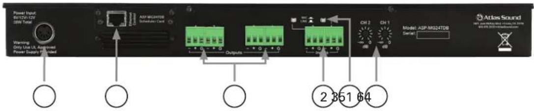
1. Power Supply Socket
An external UL rated 120V AC power supply has been included with the ASP-MG24. Only use the provided power supply due to the specific DC voltages required to operate the unit.
2. Input Connectors
There are two removable 3 Pin Phoenix type connectors for providing input signal to the unit. They can accept either a balanced or unbalanced signal. For balanced signals connect ground to (GND), positive signal to (+) and negative signal to (−). For unbalanced signals connect the (−) to the (GND) and the positive signal to (+).
3. Mic / Line Level Selection
Each input has the capability to accept either a microphone or line level signal. Prior to connecting the inputs make sure the software input gain that applies to the channel routing is set to -10dB, and the limiters are set to +20dB for gain setup. Prior to applying signal to the input, set the analog gain switch to match the type of input being used. The Line position gain is calibrated for 0dBu or unity gain within the DSP software. The Mic position gain is calibrated for -30dBu when the DSP gain is set for unity or 0dB. If more gain is needed, carefully increase the appropriate channel DSP gain in the software. If using a microphone, it is recommended to start with the input gain set to -40dB and slowly increase the input gain to the desired level.
4. Output Connectors
There are four removable 3 Pin Phoenix type connectors for providing output signal. They can deliver either a balanced or unbalanced signal. For balanced signals connect ground to (GND), positive signal to (+) and negative signal to (−). For unbalanced signals connect the (−) to the (GND) and the positive signal to (+).
5. RJ45 Port
This port allows remote configuration of the GUI via a LAN connection. A fixed IP address is needed to access the control software. Note: This port is only active with the ASP-MG24TDB.
6. Input Gain Trim Pots
Channel 1 & 2 input gain pots have an adjustment range of +6dB to -40dB. The center of pot travel is 0 gain or cut.
ASP-MG24
Owner's Manual
Getting to Know the Software
Loading the Software
- Load the software onto the computer by following the Quick Start Guide and Software Installation Guide.
- Note: It is important to have the computer screen resolution set to the highest viewing setting or a minimal setting of 1280 x 1240 pixels. Failure to do may cause the dialog boxes to appear outside the viewing area. To find a window that should appear use the master screen curser Up / Down arrows. All screens can be moved by clicking and holding the selected screen for personal viewing preferences.
- After the software is loaded and the proper screen resolution is set, open the software and follow the steps below: Note: It is not necessary to have the computer connected to the ASP-MG24 for viewing and program purposes.
Opening the Software
- The screen should look like the view below. If not, close the software and restart.
- If the ASP-MG24 is connected to the computer click "Yes" to connect, or click "No" to work in Off Line mode.
- To enter the control panel screen, click on the "Device 1" button. Note: A password can be inserted at any time. Click "Start" and then "Log On".
![Atlas Sound ASP-MG24 v1.01 [L1] Main Window [L 4] Device 1 Device 2 Device 3 Device 4 Mode Do you want to connect to the device? Yes No](/content/2026/06/1204386/images/867eaf33254e5b3283ae2be0a22b78181bb450795105f988ac2673465f0b7f0d.jpg)
![S:\Atlas Sound ASP-MG24 v1.01 [L1] Main Window [L4] Login On Password Password Entry OK Cancel](/content/2026/06/1204386/images/3a1e8e776299622f3dabb8e07e03094a61922c0886b25d621d0c322897801bb0.jpg)
Open the Device panel by clicking on "Device 1". Note: An ASP-MG24 is also known as a "Device." Multiple ASP-MG24 units can be controlled via one GUI interface. If only one ASP unit is connected to the computer click on Device 1 and the main control window will appear.
![Main Windows [L4] Server 9](/content/2026/06/1204386/images/d034c97b723bd174db551c50276dbc8829c984a31f61619fb3a1f41949a1f178.jpg)
ASP-MG24
Owner's Manual
Mic / Line Input
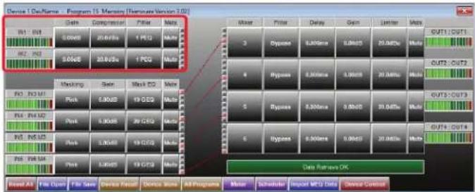
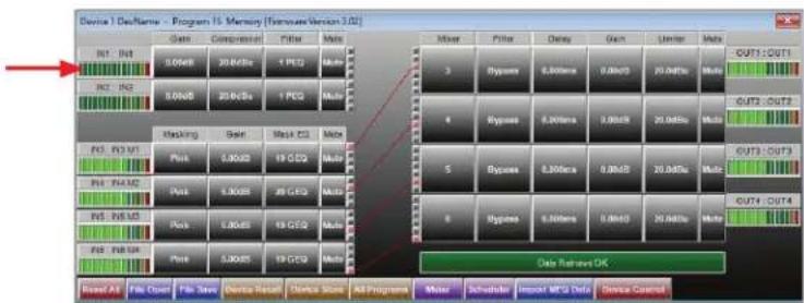
Input Meter
The bar graph meter illustrates the level of the input signal POST the channel's gain control and is PRE input filters and compressor settings.
flowchart
graph TD
    A["Device 1 Data Name - Program 15 Memory (Hardware Version 3.02)"] --> B["Data Inputs"]
    B --> C["Cache"]
    B --> D["Compression"]
    B --> E["Filter"]
    B --> F["Motor"]
    B --> G["Output Module"]
    C --> H["9.0GHz"]
    C --> I["20.0GHz"]
    C --> J["1 PEQ"]
    C --> K["Multi"]
    D --> L["8.0GHz"]
    D --> M["20.0GHz"]
    D --> N["1 PEQ"]
    D --> O["Multi"]
    E --> P["3"]
    E --> Q["8"]
    E --> R["4"]
    E --> S["5"]
    E --> T["6"]
    E --> U["7"]
    E --> V["8"]
    E --> W["8"]
    F --> X["Filter"]
    F --> Y["Duty"]
    F --> Z["Gain"]
    F --> AA["Univer"]
    F --> AB["Multi"]
    G --> AC["8.0GHz"]
    G --> AD["20.0GHz"]
    G --> AE["3.0GHz"]
    G --> AF["8.0GHz"]
    G --> AG["20.0GHz"]
    G --> AH["Multi"]
    H --> AI["8.0GHz"]
    I --> AJ["8.0GHz"]
    J --> AK["1 PEQ"]
    K --> AL["Multi"]
    L --> AM["8.0GHz"]
    M --> AN["1 PEQ"]
    N --> AO["Multi"]
    O --> AP["8.0GHz"]
    P --> AQ["8.0GHz"]
    Q --> AR["1 PEQ"]
    R --> AS["Multi"]
    S --> AT["8.0GHz"]
    T --> AU["1 PEQ"]
    U --> AV["Multi"]
    V --> AW["8.0GHz"]
    W --> AX["1 PEQ"]
    X --> AY["Multi"]
    Y --> AZ["8.0GHz"]
    Z --> BA["1 PEQ"]
    AA --> BB["Multi"]
    AB --> BC["8.0GHz"]
    AC --> BD["8.0GHz"]
    AD --> BE["1 PEQ"]
    AE --> BF["Multi"]
    AF --> BG["8.0GHz"]
    AG --> BH["1 PEQ"]
    AH --> BI["Multi"]
    AI --> BJ["8.0GHz"]
    AK --> BK["1 PEQ"]
    AL --> BL["Multi"]
    AM --> BM["8.0GHz"]
    AN --> BN["1 PEQ"]
    AO --> BO["Multi"]
    AP --> BP["8.0GHz"]
    AQ --> BQ["1 PEQ"]
    AR --> BR["Multi"]
    AS --> BS["8.0GHz"]
    AT --> BT["1 PEQ"]
    AU --> BU["Multi"]
    AV --> BV["8.0GHz"]
    AW --> BW["1 PEQ"]
    AX --> BX["Multi"]
    AY --> BY["8.0GHz"]
Gain
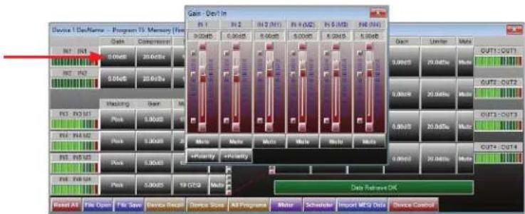
For convenience both Mic / Line inputs and the four masking generators levels are shown. Controlling the gain can be accomplished by dragging the fader, using the up / down buttons or by typing in the number viewing text box. Channel Mute can be accomplished by clicking on the Mute tab. The tab will illuminate red indicating the channel is in Mute. Input Polarity can be set by clicking on the Polarity tab.
ASP-MG24
Owner's Manual
Compressor
Inputs 1 & 2 have fully adjustable compressor limiters. When clicking on the compressor tab, two sub viewing screens will appear. Note: All control boxes can be dragged for desired positioning of the screen. Screen 1 is an indicator screen showing the compressor / limiter operation. The second is the settings screen. This screen controls Threshold, Attack, Release and Ratio. Adjustment can be made using the up / down arrows or by typing into the data viewing text box.
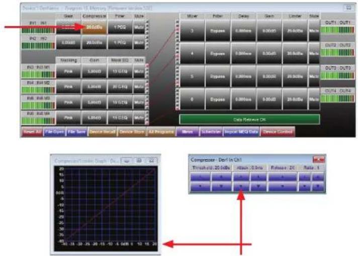
- Threshold - Limit threshold. Ranges from -20dBu to +20dBu in 0.5dB steps.
- Attack - Attack time. Ranges from 0.3ms to 1ms in 0.1ms steps, and ranges from 1ms to 100ms in 1ms steps.
- Release - Release time. Can be set at 2X, 4X, 8X, 16X or 32X the attack time.
• Ratio - The Ratio control allows adjustment to the amount of Input vs. Output level with signals exceeding the set threshold limit.
Example: When set at "2", a 2dB input signal increase yields 1dB output gain.
ASP-MG24
Owner's Manual
Filter
When clicking on the filter button 3 sub viewing screens appear. There are 8 bands of full parametric EQ and Hi Cut / Lo Cut filters available per input. Note: If the screens do not appear change the screen resolution. Also use the screen curser up / down arrows to find the three screens. All 3 screens can be moved by clicking and holding the selected screen for personal viewing preferences.
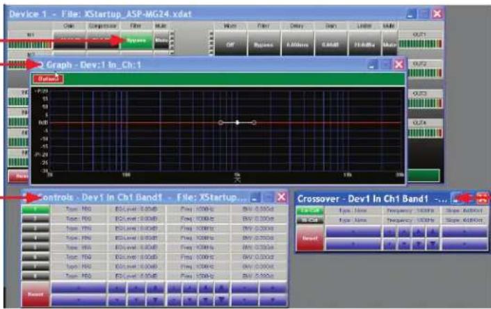
Graphic Screen
This screen will display all of the filter characteristics that are set.
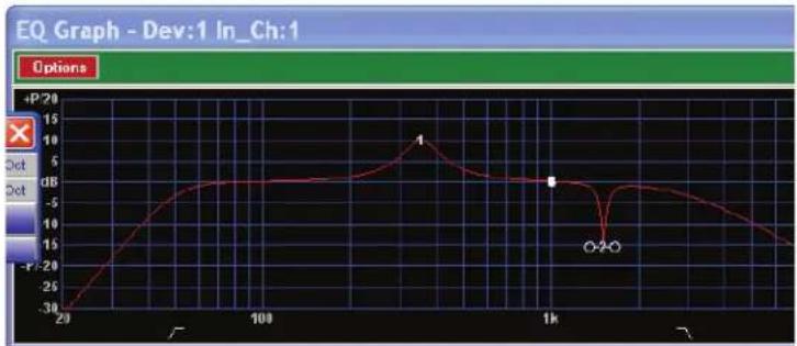
line
| x | y | | ---- | ----- | | 20 | -30 | | 100 | 0 | | 1k | 0 | | >1k | -15 |Filter Adjust Window
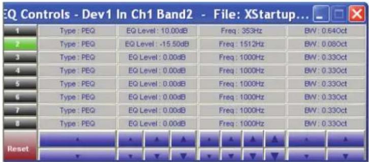
Each input has 8 adjustable filter selections. the choices are Parametric, Hi-shelf and Lo-shelf. Adjustments can be made via the up / down arrows, text window and by dragging the curser on the Graphics Screen. Any adjustments made should appear on the Graphic Screen.

Atlas

1601 JACK MCKAY BLVD
ENNIS, TEXAS 75119 U.S.A.
TELEPHONE: (800) 876-3333
SUPPORT@ATLASIED.COM
AtlasIED.com
ASP-MG24
Owner's Manual
Crossover Window
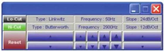
The Crossover window allows the adjustment of filter type, frequency, and slope. The Reset button will set all filters back to factory settings and only affects the settings on this screen.
Mute
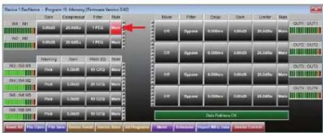
This button mutes the signal at the input of the channel. It will illuminate red when pressed.
ASP-MG24
Owner's Manual
Masking Generator Inputs
Meter
There are four bar graph meters that illustrate the level of the output signal of the generator. It is POST the channel's gain control and PRE input filters.
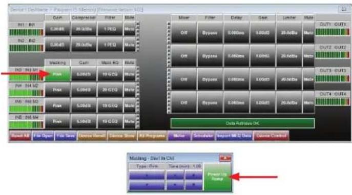
Masking
When the Masking button is pressed a small window will open. This window allows the selection of either the White or Pink noise filter.
Ramp Time
The Power Ramp button sets the desired turn on signal ramp time during power up. The Time buttons allow adjustment of the amount of preset time needed. The amount of steps is a formula of gain divided by time. The ramp interval voltage change will occur every 6 seconds. The amount of dB steps will vary depending on the total ramp time selected and the change in gain from -40dB. Example: Choosing 2 minutes of ramp time with channel gain set to -10dB, use the following formula to calculate dB rate of change:
(Gain = -40dB minus -10dB = -30dB) and (Time = 120 seconds / 6 seconds = 20 steps) Gain Steps = 30dB / 20 steps = 1.5 dB change per second.
Ramp Bypass
If the Power Up Ramp button is illuminated green the ramp feature is engaged, if grey the feature is bypassed.
ASP-MG24
Owner's Manual
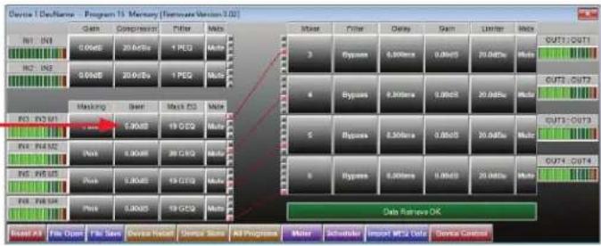
Gain
For convenience both Mic / Line Inputs and the 4 masking generators levels are shown. Controlling the gain can be accomplished by dragging the fader, using the up / down buttons, or typing in the number viewing text box. Channel Mute can be accomplished by clicking on the Mute button. It will illuminate red indicating the channel is in Mute.
flowchart
graph TD
    A["Input Module"] --> B["Masking"]
    B --> C["Filter"]
    C --> D["Max"]
    D --> E["Output Module"]
    E --> F["Data Return OK"]
    style A fill:#f9f,stroke:#333
    style F fill:#bbf,stroke:#333
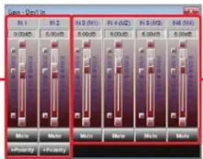
Masking GainMic / Line Input Gain
Masking EQ
When clicking on the filter screen, 3 sub viewing screens appear. Note: All 3 screens can be moved for personal viewing preferences.
line
| Point | Value | |-------|-------| | 1 | 8 | | 2 | 9 | | 3 | 10 | | 4 | 11 | | 5 | 12 | | 6 | 13 | | 7 | 14 | | 8 | 15 | | 9 | 16 | | 10 | 17 | | 11 | 18 | | 12 | 19 | | 13 | 20 | | 14 | 21 | | 15 | 22 | | 16 | 23 | | 17 | 24 | | 18 | 25 | | 19 | 26 | | 20 | 27 | | 21 | - | | 22 | - | | 23 | - | | 24 | - | | 25 | - | | 26 | - | | 27 | - | | 28 | - | | 29 | - | | 30 | - |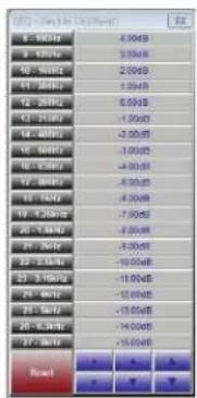
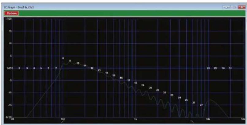
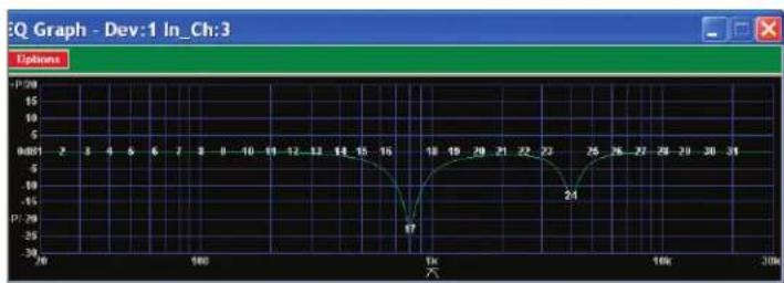
This screen will display all of the filter characteristics that are set. There 31 filter select points on the screen. Move the cursor over the number and click and drag the filter to adjust the amount of boost or cut for a specified 13 octave frequency.
line
EQ Graph - Dev:1 In_Ch:3 | Time (s) | Value | | :--- | :--- | | 26 | 17 | | 30 | 24 | | 35 | 28 | | 40 | 29 | | 45 | 27 | | 50 | 28 | | 55 | 29 | | 60 | 28 | | 65 | 27 | | 70 | 26 | | 75 | 25 | | 80 | 24 | | 85 | 23 | | 90 | 22 | | 95 | 21 | | 100 | 20 | | 105 | 19 | | 110 | 18 | | 115 | 17 | | 120 | 16 | | 125 | 15 | | 130 | 14 | | 135 | 13 | | 140 | 12 | | 145 | 11 | | 150 | 10 | | 155 | 9 | | 160 | 8 | | 165 | 7 | | 170 | 6 | | 175 | 5 | | 180 | 4 | | 185 | 3 | | 190 | 2 | | 195 | 1 | | 200 | 0 | | 205 | -1 | | 210 | -2 | | 215 | -3 | | 220 | -4 | | 225 | -5 | | 230 | -6 | | 235 | -7 | | 240 | -8 | | 245 | -9 | | 250 | -10 | | 255 | -11 | | 260 | -12 | | 265 | -13 | | 270 | -14 | | 275 | -15 | | 280 | -16 | | 285 | -17 | | 290 | -18 | | 295 | -19 | | 300 | -20 | | 305 | -21 | | 310 | -22 | | 315 | -23 | | 320 | -24 | | 325 | -25 | | 330 | -26 | | 335 | -27 | | 340 | -28 | | 345 | -29 | | 350 | -30 | | 355 | -31 | | 360 | -32 | | 365 | -33 | | 370 | -34 | | 375 | -35 | | 380 | -36 | | 385 | -37 | | 390 | -38 | | 395 | -39 | | 400 | -40 | | 405 | -41 | | 410 | -42 | | 415 | -43 | | 420 | -44 | | 425 | -45 | | 430 | -46 | | 435 | -47 | | 440 | -48 | | 445 | -49 | | 450 | -50 | | 455 | -51 | | 460 | -52 | | 465 | -53 | | 470 | -54 | | 475 | -55 | | 480 | -56 | | 485 | -57 | | 490 | -58 | | 495 | -59 | | 500 | -60 | | 505 | -61 | | 510 | -62 | | 515 | -63 | | 520 | -64 | | 525 | -65 | | 530 | -66 | | 535 | -67 | | 540 | -68 | | 545 | -69 | | 550 | -70 | | 555 | -71 | | 560 | -72 | | 565 | -73 | | 570 | -74 | | 575 | -75 | | 580 | -76 | | 585 | -77 | | 590 | -78 | | 595 | -79 | | 600 | -80 | | 605 | -81 | | 610 | -82 | | 615 | -83 | | 620 | -84 | | 625 | -85 | | 630 | -86 | | 635 | -87 | | 640 | -88 | | 645 | -89 | | 650 | -90 | | 655 | -91 | | 660 | -92 | | 665 | -93 | | 670 | -94 | | 675 | -95 | | 680 | -96 | | 685 | -97 | | 690 | -98 | | 695 | -99 | | 700 | -100| | 705 | -101| | 710 | -102| | 715 | -103| | 720 | -104| | 725 | -105| | 730 | -106| | 735 | -107| | 740 | -108| | 745 | -109| | 750 | -110| | 755 | -111| | 760 | -112| | 765 | -113| | 770 | -114| | 775 | -115| | 780 | -116| | 785 | -117| | 790 | -118| | 795 | -119| | 800 | -120| | 805 | -121| | 810 | -122| | 815 | -123| | 820 | -124| | 825 | -125| | 830 | -126| | 835 | -127| | 840 | -128| | 845 | -129| | 850 | -130| | 855 | -131| | 860 | -132| | 865 | -133| | 870 | -134| | 875 | -135| | 880 | -136| | 885 | -137| | 890 | -138| | 895 | -139| | 900 | -140| | 905 | -141| | 910 | -142| | 915 | -143| | 920 | -144| | 925 | -145| | 930 | -146| | 935 | -147| | 940 | -148| | 945 | -149| | 950 | -150| | 955 | -151| | 960 | -152| | 965 | -153| | 970 | -154| | 975 | -155| | 980 | -156| | 985 | -157| | 990 | -158| | 995 | -159| | ... (Repeated) ... (Repeated) ... (Repeated) ... (Repeated) ... (Repeated) ... (Repeated) ... (Repeated) ... (Repeated) ... (Repeated) ... (Repeated) ... (Repeated) ... (Repeated) ... (Repeated) ... (Repeated) ... (Repeated) ... (Repeated) ... (Repeated) ... (Repeated) ... (Repeated) ... (Repeated) ... (Repeated) ... (Repeated) ... (Repeated) ... (Repeated) ... (Repeated) ... (Repeated)
Atlas

1601 JACK MCKAY BLVD
ENNIS, TEXAS 75119 U.S.A.
TELEPHONE: (800) 876-3333
SUPPORT@ATLASIED.COM
AtlasIED.com
ASP-MG24
Owner's Manual
1/3 Octave Graphic Screen
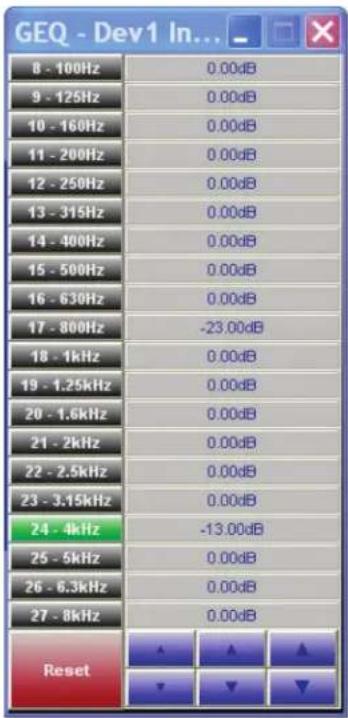
Adjustments to the filters can be made dragging the filter number on the screen or by using the up / down arrows. The Reset button will set all filters back to factory settings and only effects the settings in this screen. There are 20½ octave band filters available to adjust the measured masking signal. A generous +15dB and -30dB boost and cut are offered in 0.25dB steps.
Crossover Window
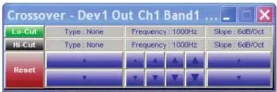
The Crossover window allows the adjustment of filter type, frequency, and slope. The Reset button will set all filters back to factory settings. This Reset button only effects the settings in this screen.
Mute
This button mutes the signal at the input of the channel. It will illuminate red when pressed.

Atlas

1601 JACK MCKAY BLVD
ENNIS, TEXAS 75119 U.S.A.
TELEPHONE: (800) 876-3333
SUPPORT@ATLASIED.COM
AtlasIED.com
ASP-MG24
Owner's Manual
Masking Generator Outputs
![Device 1 DevName - Program 13 Memory [Renewater Version 1.02] Gain Compressor Filter Mode B1: B4 1.0GHz 20.0GHz 1.9GHz Mode B2: B2 5.0GHz 20.0GHz 1.9GHz Mode Masking Gain Max BD Mode B3: B3.0Hz Park 0.0GHz 19 GHz Mode B4: B4.0Hz Park 0.0GHz 20.0GHz Mode B5: B5.0Hz Park 0.0GHz 19 GHz Mode B6: B6.0Hz Park 5.0GHz 18 GHz Mode Mixer Filter Delay Gain Litter Mode 3 Dyspase 6.0GHz 0.0GHz 20.0GHz Mio 4 Dyspase 6.0GHz 0.0GHz 20.0GHz Mio 5 Dyspase 6.0GHz 0.0GHz 21.0GHz Mio 6 Dyspase 6.0GHz 0.0GHz 20.0GHz Mio Data Transfer OK Event A3 File Open File Save Device Name Device Start All Programs Meter Subtractor Import MD Data Device Control](/content/2026/06/1204386/images/3a2487b39b096f865e919cc3b19c7db66e41e0832c9d8c168afa0ea00f421f9c.jpg)
Mixer
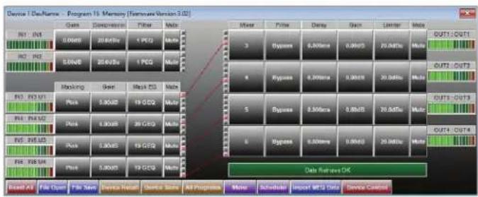
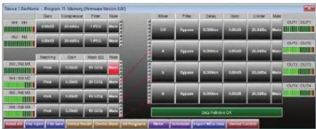
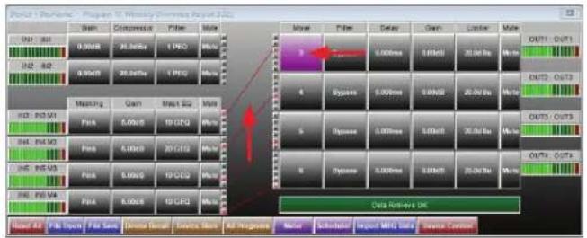
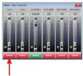
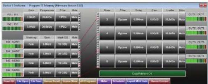
This button will route or mix any of the inputs to this output. When clicking on this button a window will appear that shows all 6 inputs. Each input channel gain operates from Off to 0dB. Controlling the mixed gain can be accomplished by dragging the fader, using the up / down buttons, or typing in the number viewing text box. Note: The signal feeding into the mixer will not be effected by other output channel mixes. Once the routing or mix is complete, view the route by the channel indicator lines or by the number of channels indicated in the mixer viewing window. An alternative to using the mixer window is to click on the small gray box on either the 6 inputs or 4 outputs. These connect the specific channel to the output.
ASP-MG24
Owner's Manual
Filter
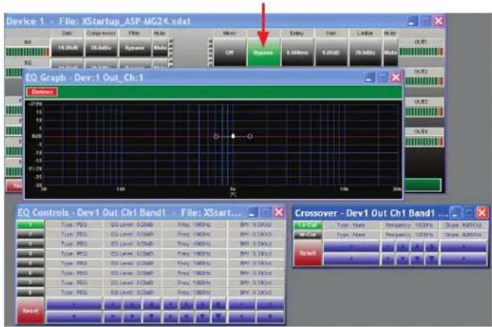
When clicking on the filter screen 3 sub viewing screens appear. This allows access to 8 full parametric EQ's per output channel. Note: All 3 screens can be moved for personal viewing preferences.
Graphic Screen
This screen will display all of the filter characteristics that are set.
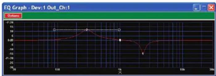
line
| X | Y | |-------|-------| | 20 | 0 dB | | 100 | 10 dB | | 1k | 0 dB | | 10k | -18 dB| | 30k | 0 dB |Filter Window
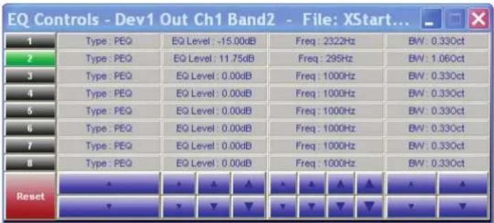
Each input has 8 adjustable filter selections. The choices are Parametric, and Hi cut and Lo cut filters with up to 48dB/octave filter slope. Adjustments can be made via the up / down arrows, text window and by dragging the curser on the Graphics Screen. After any adjustments are made, they should appear on the Graphic Screen.
ASP-MG24
Owner's Manual
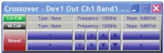
Crossover Window
The Crossover window allows the adjustment of filter type, frequency, and slope. The Reset button will set all filters back to factory settings. This Reset button only effects the settings in this screen.
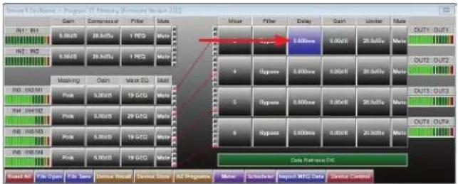
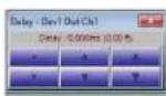
Delay Window
The Delay window allows adjustment of the channel delay from 0ms to 200ms per output. Controlling the mixed gain can be accomplished by using the up / down buttons or by typing in number viewing text box.
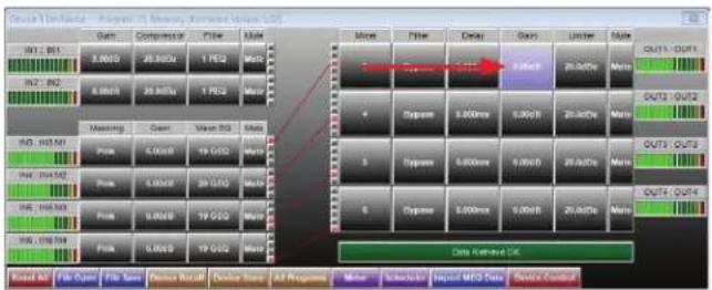
Gain
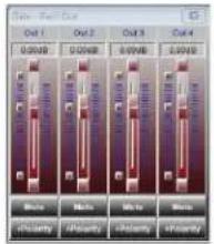
The 4 output gain levels are shown when clicking on this window. Controlling the gain can be accomplished by dragging the fader or by using the up / down buttons. Channel Mute can be accomplished by clicking on the Mute tab. It will illuminate red indicating the channel is in Mute. Input Polarity can be set by clicking on the tab.
flowchart
graph TD
    A["Input Data"] --> B["Data Input"]
    B --> C{Data Breakthrough}
    C -->|Yes| D["Control Logic"]
    C -->|No| E["Output"]
    D --> F["Data Output"]
    F --> G{Data Enable?}
    G -->|Yes| H["Control Logic"]
    G -->|No| I["Output"]
    H --> J["Output"]
    style A fill:#f9f,stroke:#333
    style J fill:#bbf,stroke:#333
ASP-MG24
Owner's Manual
Limiter
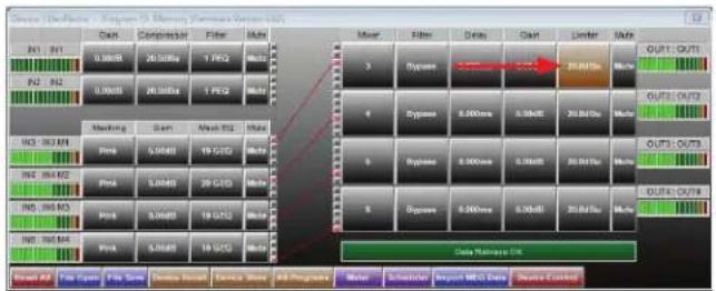
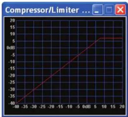
All 4 outputs have fully adjustable hard limiters. When clicking on the limiter tab, 2 sub viewing screens will appear. Note: All control boxes can be dragged for desired positioning of the screen. Screen 1 is an indicator screen showing the compressor / limiter operation. Screen 2 is the settings screen which controls Threshold, Attack, Release and Ratio. Adjustment can be made using the up / down arrows.
line
| X | Y | |---|---| | -25 | -40 | | -20 | -35 | | -15 | -30 | | -10 | -25 | | -5 | -20 | | 0 | -15 | | 5 | -10 | | 10 | -5 | | 15 | 0 | | 20 | 5 | | 25 | 10 | | 30 | 15 | | 35 | 20 | The chart displays a single data series with X and Y values for each data point. The X-axis is labeled as 'X', and the Y-axis is labeled as 'Y'. There are no labels or additional data series in this image.
- Threshold - Limit Threshold. Ranges from -20 to +20dBu in 0.5dB steps.
- Attack - Attack time. Ranges from 0.3 to 1ms in 0.1ms steps, and ranges from 1 to 100ms in 1ms steps.
- Release - Release time. Can be set at 2X, 4X, 8X, 16X or 32X the attack time.
• Ratio - The Ratio control allows adjustment to the amount of Input vs. Output level with signals exceeding the set threshold limit.
line
Compressor/Limiter ... | X-axis | Y-axis | |---|---| | -40 | -40 | | -35 | -35 | | -30 | -30 | | -25 | -25 | | -20 | -20 | | -15 | -15 | | -10 | -10 | | -5 | -5 | | 0 | 0 | | 5 | 5 | | 10 | 7.5 | | 15 | 8 | | 20 | 8 |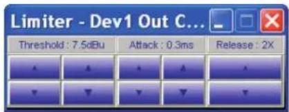
ASP-MG24
Owner's Manual
Mute
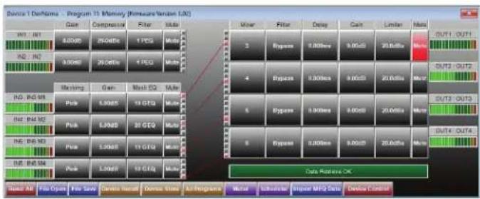
Channel Mute can be accomplished by clicking on the Mute tab and will illuminate red indicating the channel is in Mute.
flowchart
graph TD
    A["Program 15 Memory (Membrane Version LNC)"] --> B["Data Flow: Main Components"]
    B --> C["Output Format: OUT1, OUT2, OUT3, OUT4"]
    C --> D["Data Inputs: Main Components"]
    D --> E["Output Format: Out1, Out2, Out3, Out4"]
    E --> F["Output Format: Out1, Out2, Out3, Out4"]
    F --> G["Data Inputs: Main Components"]
    G --> H["Output Format: Out1, Out2, Out3, Out4"]
    H --> I["Output Format: Out1, Out2, Out3, Out4"]
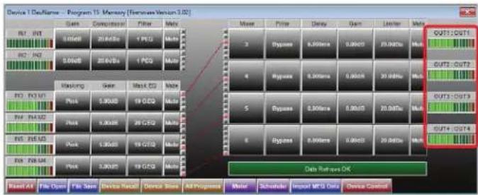
Output Meter
The bar graph meter illustrates the level of the output signal POST the channels gain control and filters but is PRE Limiter settings.
ASP-MG24
Owner's Manual
File Import and Export
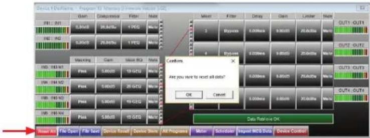
Master Reset All
This button is the master reset button and will override all settings. Note: A confirmation widow will pop up.
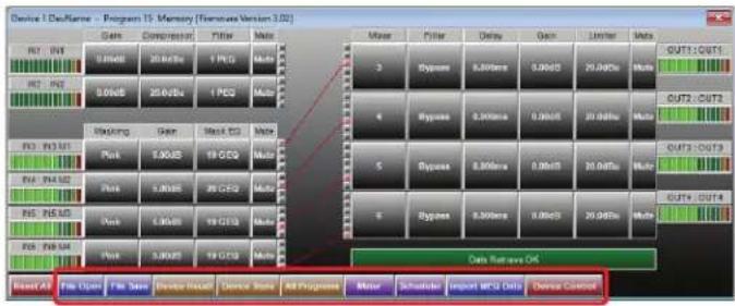
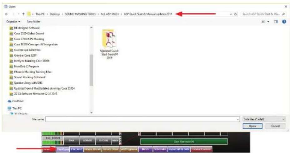
File Open
Program files can be recalled from the PC or Laptop. It operates like any other Windows ^® files storing device. For convenience a file can be preprogrammed in demo mode, saved and loaded to the device.
ASP-MG24
Owner's Manual
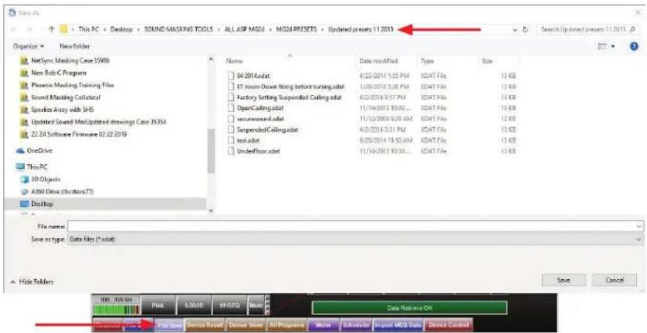
File Save
Program files can be saved to the PC or Laptop. It operates like any other Windows® files storing device. For convenience a file can be preprogrammed in demo mode, saved and loaded to the device.
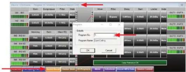
Device Recall
The ASP-MG24 has a built in non-volatile memory that can store up 14 different program setups. A program can be recalled from the device. When doing so, only one program can be open on the desktop GUI. Once recalled, the program name and number will be at the top of the main screen.
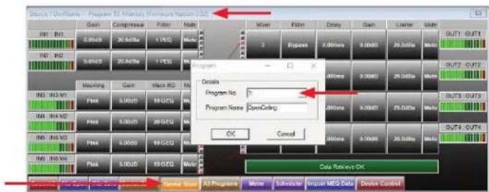
Device Store
The ASP-MG24 has a built in non-volatile memory that can store up 14 different program setups. A program can be stored using this menu. The old program with the same program number will be replaced. Once the program is stored in the flash memory, it can be recalled at a later time, even after loss of power.
ASP-MG24
Owner's Manual
All Programs
Upload / download up to 14 programs containing multiple loudspeaker EQ parameters and sound masking setups.
Meter
Real time meters for all inputs / outputs. Scaled in V(RMS), dBu and dBV. These are helpful when troubleshooting.
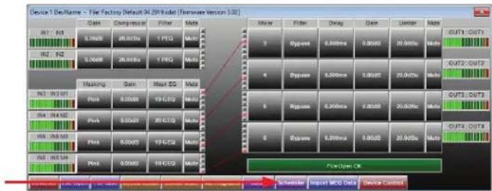
Scheduler
The ASP-MG24TDB contains a programmable clock and setup for time based masking level changes plus the Initial Ramp Configuration.
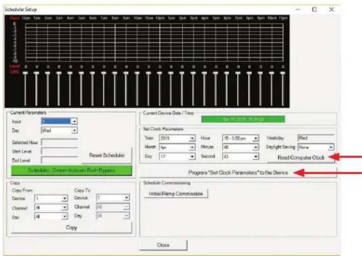
Press "Read Computer Clock" to set the correct time and date.
Then press "Set Clock Parameters to Device" to load clock settings into the device.
ASP-MG24
Owner's Manual
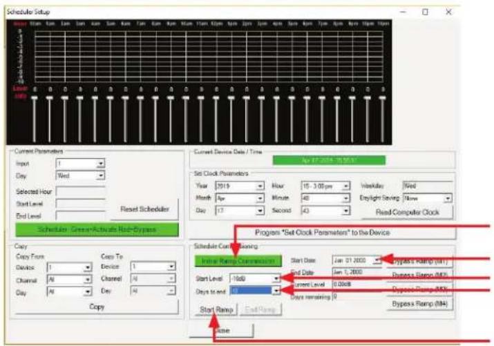
For Retrofit Sound Masking installations where the occupants are already in the space, this feature programs a one-time slow ramp to allow the occupants to become accustomed to the masking sound in the space.
- Click the Initial Ramp Commission button.
- Click the Start Date drop down menu and select the start date.
- Set the start level for the masking signal, typically -10dB down from the target level.
- Click the Days to End drop down menu and select how many days the scheduler will ramp up.
- Click the Start Ramp button.
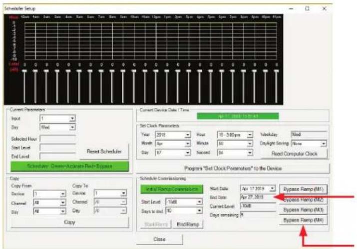
Once the Initial Ramp Setup is complete, the starting level is 10dB below the target level, and the device is programmed to take 10 days to return to the target level. The Bypass Ramp buttons allow the 4 masking channels to be bypassed.
ASP-MG24
Owner's Manual
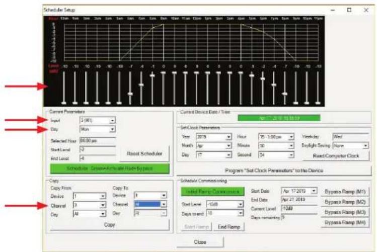
The Scheduler allows the installer to program masking level changes over a 24 hour period, 7 days a week. A separate schedule can be configured for every day and can be copied to any of the 4 masking channels and the 2 inputs. This example shows Masking channel M1, with a program for Monday, ramping up slowly starting at 5am and ramping down starting at 4pm. The faders set the masking level from "0" level change down to -10dB. Drop down menus allow selection of any of the 4 masking channels and 2 inputs to be configured to a schedule, as well as choosing the day of the week to program. To reduce data entry time, create a schedule for one day and copy it to all the other days. The Channel 3 or "M1" schedule is getting copied to all the remaining 6 days.
Device Control
Enter device "name", as well as access Ethernet Setup for MAC Address, IP address, Gateway and Subnet Mask.
Import MEQ Data
Directly import files from the AtlasLED room measurement software called MEQ. This is an advanced feature, contact support for more details.
![Atlas Sound ASP-MG24 v1.01 [L4] Test Copy Help Device 1 - Program 1 Open Ceiling Open Compressor Filter Make 3.0MB 25.0MB 4 PCD MDD 3.0MB 25.0MB 4 PCD MDD Type Type Type Type Type Type Type Type Type Type Type Type Type Type Type Type Type Type Type Type Type Type Type Type Type Type Type Type Type Type Type Type Type Type Type Type Type Type Type Type Type Type Type Type Type Type Type Type Type Type Open Look in Bob Reset Files My Recent Exchange to Backup My Documents My Computer My Network, Flats: File name: MBQ Data Bus7*60J File of type: MBQ Data Bus7*60J](/content/2026/06/1204386/images/65a37235325819da55f82d2a2ef2ba37b943776c1661923d1e43f7ad89e128a0.jpg)
Sync Process
This window indicates the status of the connection between the GUI software and the devices. This window corresponds with Setup/ Port Connection window at the top of the page.
ASP-MG24
Owner's Manual
| System | |
| Type DSP Controller 2x4 Speaker Processor / Masking Generator | |
| Power Supply Type 90 - 240VAC 20W Universal UL | Rated External DC Power Supply |
| Front Panel | |
| Level Meters In / Out 5 Segment LED | |
| RS-232 Female DB-9 | |
| Power Indicator Blue LED | |
| Data Status Indicator Green LED | |
| USB Interface Female USB | |
| Rear Panel | |
| Inputs 2 Selectable Mic / Line Inputs, 3-pin Balanced Phoenix | |
| Input Switch 2 Mic / Line Switches | |
| Trim Pots 2 Input Gain Trim Pots (-TDB Only) | |
| Outputs 4 Outputs, 3-pin Balanced Phoenix | |
| DC Power Receptacle | 5 Pin DIN Connector |
| Audio Control Parameters | |
| Gain | -40dB to +15dB in 0.25dB Steps |
| Polarity + / - | |
| Delay | Up to 200ms per I/O |
| Parametric Filters (8 per I/O) | True parametric with boost / cut, center frequency and filter bandwidth |
| Filter Bandwidth (Parametric) | 0.02 to 2.50 Octaves (Q=0.5 to 72) |
| Masking Inputs | 4 Independent GeneratorsWhite or Pink Noise31 Band EQ per OutputGain per OutputTurn on Auto Ramp 0:00 – 10:00 Min |
| Crossover Filters | Filter Types: Butterworth, Bessel, Linkwitz RileySlopes: 6 to 48dB / Oct |
| Compressor / Limiters | Threshold: -20 to +20dBuRatio: 1:40Attack: 0.3 to 100msRelease: 2 to 32X the Attack Time |
| System Parameters | |
| Number of Programs | 14 |
| Program Names | 12 Character Length |
| Delay Units | ms, ft, m |
| Security Locks | System |
ASP-MG24
Owner's Manual
| Electrical Specifications (General) | |
| Input Impedance Line 10k Ohms, Mic | |
| Output Impedance 50 Ohms | |
| Maximum Input & Output Level +20dBu | |
| Frequency Response 20Hz - 20kHz (+/- 0.1dB) | |
| Dynamic Range 115dB (unweighted) | |
| CMMR > 60dB (50 to 10kHz) | |
| Crosstalk < -100dB | |
| Distortion 0.02% (1kHz @+4dBu) | |
| Processor 32-bit (40-bit extended) | |
| Sampling Rate 96kHz | |
| Analog Converters High Performance 24-bit | |
| Propagation Delay 3ms | |
| Electrical Specifications (General) | |
| Input Impedance Line 10k Ohms, Mic | |
| Output Impedance 50 Ohms | |
| Maximum Input & Output Level +20dBu | |
| Frequency Response 20Hz - 20kHz (+/- 0.1dB) | |
| Dynamic Range 115dB (unweighted) | |
| CMMR > 6dB (50 to 10kHz) | |
| Crosstalk < -100dB | |
| Distortion 0.02% (1kHz @+4dBu) | |
| Processor 32-bit (40-bit extended) | |
| Sampling Rate 96kHz | |
| Analog Converters High Performance 24-bit | |
| Propagation Delay 3ms | |
| Dimensions and Weight | |
| Rack Mount Requirements 1 RU, 19' | |
| Dimensions - Unit | W 19" x H 1.75" x D 8" (483mm x 44mm x 203mm) |
| Dimensions - Shipping | W 24.75" x H 3.15" x D 14.15" (628mm x 80mm x 359mm) |
| Weight - Unit | 7lb (3.2kg) |
| Weight - Shipping | 10lb (4.5kg) |
ASP-MG24
Owner's Manual
Dimensional Drawings
![19.00 [483] 1.75 [44] USB System Control RS232 1 2 OverLine M/F Signal 123 4 Output Atlas Sound ASP-MG24 Evid Signal Processor/Measuring Generator Power Data](/content/2026/06/1204386/images/983f6b5b9d0fe071b52d5494162611b8fc4d33d1a034246a7bae0ae7d828bb75.jpg)
![8 [203] 17.00 [431]](/content/2026/06/1204386/images/cde3bc9d695ebca1120604af4118293a02d00510cd24446c4c3bcdc0f0e4d685.jpg)
![1.75 [44] 8 [203]](/content/2026/06/1204386/images/f32b974303813416c0215f7fed30fe66d6639ab08de8f606f1a2cdfe2216487c.jpg)
ASP-MG24
Owner's Manual
Notes:
ASP-MG24
Owner's Manual
Notes:
ASP-MG24
Owner's Manual
Notes:
Limited Warranty
All products manufactured by AtlasIED are warranted to the original dealer/installer, industrial or commercial purchaser to be free from defects in material and workmanship and to be in compliance with our published specifications, if any. This warranty shall extend from the date of purchase for a period of three years on all AtlasIED products, including SOUNDOLIER brand, and ATLAS SOUND brand products except as follows: one year on electronics and control systems; one year on replacement parts; and one year on Musician Series stands and related accessories. Additionally, fuses and lamps carry no warranty. AtlasIED will solely at its discretion, replace at no charge or repair free of charge defective parts or products when the product has been applied and used in accordance with our published operation and installation instructions. We will not be responsible for defects caused by improper storage, misuse (including failure to provide reasonable and necessary maintenance), accident, abnormal atmospheres, water immersion, lightning discharge, or malfunctions when products have been modified or operated in excess of rated power, altered, serviced or installed in other than a workman like manner. The original sales invoice should be retained as evidence of purchase under the terms of this warranty. All warranty returns must comply with our returns policy set forth below. When products returned to AtlasIED do not qualify for repair or replacement under our warranty, repairs may be performed at prevailing costs for material and labor unless there is included with the returned product(s) a written request for an estimate of repair costs before any nonwarranty work is performed. In the event of replacement or upon completion of repairs, return shipment will be made with the transportation charges collect.
EXCEPT TO THE EXTENT THAT APPLICABLE LAW PREVENTS THE LIMITATION OF CONSEQUENTIAL DAMAGES FOR PERSONAL INJURY, ATLASIED SHALL NOT BE LIABLE IN TORT OR CONTRACT FOR ANY DIRECT, CONSEQUENTIAL OR INCIDENTAL LOSS OR DAMAGE ARISING OUT OF THE INSTALLATION, USE OR INABILITY TO USE THE PRODUCTS. THE ABOVE WARRANTY IS IN LIEU OF ALL OTHER WARRANTIES INCLUDING BUT NOT LIMITED TO WARRANTIES OF MERCHANTABILITY AND FITNESS FOR A PARTICULAR PURPOSE.
AtlasIED does not assume, or does it authorize any other person to assume or extend on its behalf, any other warranty, obligation, or liability. This warranty gives you specific legal rights and you may have other rights which vary from state to state.
Service
Should your ASP-MG24 / ASP-MG24TDB require service, please contact the AtlasLED warranty department at 1-800-876-3333 or atlaswarranty@atlasied.com to obtain an RA number.
AtlasIED Tech Support can be reached at 1-800-876-3333 or www.atlasied.com/support.
Visit our website at www.atlasied.com to see other AtlasIED products.
©2019 Atlas Sound L.P. The Atlas "Circle A", Soundolier, and Atlas Sound are trademarks of Atlas Sound L.P. IED is a registered trademark of Innovative Electronic Designs LLC. All Rights Reserved. All other trademarks are the property of their respective owners. All specs are subject to change without notice. ATS002766 RevC 4/19
- ASP-MG24 / ASP-MG24TDB
- Signal Processor / Masking Generator 2 Input x 4 Output
- ASP-MG24
- Table of Contents
- Owner's Manual
- Important Safety Instructions
- NING - When The Device Is In Use
- TION - When Installing The Product
- TION - When The Product Is In Use
- Introduction
- Key Features
- LED Power Indicator
- Level LED Indicators
- RS232 Connector
- USB Connector
- LED Data Indicator
- Rear Panel
- Power Supply Socket
- Input Connectors
- Mic / Line Level Selection
- Output Connectors
- RJ45 Port
- Input Gain Trim Pots
- Getting to Know the Software
- Loading the Software
- Opening the Software
- Mic / Line Input
- Input Meter
- Gain
- Compressor
- Filter
- Graphic Screen
- Filter Adjust Window
- Crossover Window
- Mute
- Masking Generator Inputs
- Meter
- Masking
- Ramp Time
- Ramp Bypass
- Masking EQ
- 1/3 Octave Graphic Screen
- Masking Generator Outputs
- Mixer
- Filter Window
- Delay Window
- Limiter
- Output Meter
- File Import and Export
- Master Reset All
- File Open
- File Save
- Device Recall
- Device Store
- All Programs
- Scheduler
- Device Control
- Import MEQ Data
- Sync Process
- Limited Warranty
- Service
Brand : Atlas Sound
Model : ASP-MG24TDB
Category : Hi-Fi System