TSD-DA13 - Hi-Fi System Atlas Sound - Free user manual and instructions
Find the device manual for free TSD-DA13 Atlas Sound in PDF.


| Product Type | 1x3 Mic/Line Distribution Amplifier |
| Dimensions (H x W x D) | 1.5" x 4" x 2.75" (39 x 101 x 70 mm) |
| Weight | 6 oz (0.165 kg) |
| Power Supply | 24 V DC, 60 mA, 1.4 W |
| Inputs | 1 balanced mic/line (Phoenix, 3.5mm pitch) + 1 summed dual RCA (unbalanced) |
| Outputs | 3 balanced mic/line (Phoenix, 3.5mm pitch), isolated |
| Frequency Response | 20 Hz – 20 kHz (±1 dB) |
| THD | 0.06% at 1 kHz |
| Signal-to-Noise Ratio | Line to Line: 85 dBV, Mic to Line: 78 dBV |
| Phantom Power | 24 V DC, switchable via DIP |
| Low Cut Filter | 125 Hz, 12 dB/octave, defeatable |
| Indicators | Power (blue), Signal (green, 25 mV threshold), Peak (red, -3 dB before clip) |
| Controls | Input level (1), output levels (3), DIP switches (6) |
| Security Covers | Removable knobs with tamper-proof covers included |
| Mounting Options | Velcro, multi-mount plate, optional rack kits (19", half-width, rear) |
| Chassis Material | Black aluminum |
| Warranty | 3 years (limited) |
| Certifications | cUL, CE, RoHS, TUV (external PSU); Energy Star ™ compliant |
Frequently Asked Questions - TSD-DA13 Atlas Sound
User questions about TSD-DA13 Atlas Sound
0 question about this device. Answer the ones you know or ask your own.
Ask a new question about this device
Download the instructions for your Hi-Fi System in PDF format for free! Find your manual TSD-DA13 - Atlas Sound and take your electronic device back in hand. On this page are published all the documents necessary for the use of your device. TSD-DA13 by Atlas Sound.
USER MANUAL TSD-DA13 Atlas Sound
The AtlasIED TSD-DA13 1x3 distribution amplifier is designed to provide clean, isolated signal distribution locally or to remote locations. The unit allows a balanced mic or line level source to be distributed to three isolated variable outputs making it a perfect solution for applications including convention centers, houses of worship, restaurants/sports bars and industrial facilities.
A high quality, low noise mic pre-amp, defeatable 12dB low cut filter @ 125Hz and dual summing RCA line level inputs are included as part of the unit's input section. These features combined with the 3 mic / line level outputs allow for multiple configuration.
Isolation between outputs prevents crosstalk, removes miss matched input impedance concerns and allows for adjustable levels on each connected device.
All I/O (except the summing RCA inputs) is via Phoenix style connectors for installation convenience.
The TSD-DA13 is highly efficient and meets Energy Star ^™ standards as one 24V DC power supply (available separately) can power multiple Atlas Time Saving Devices.
The TSD-DA13 is part of a full line of AtlasIED Time Saving Devices. These compact (1.5" x 4" x 2.75") units are designed to solve some of the common audio system problems in the easiest and in the most efficient and cost-effective way. All models are made from high quality components and include removable individual I/O connectors for quick and precise wiring, separate ground terminals for all I/Os assuring secured connections, and removable level controls that can be replaced with tamper-proof security covers.
Features
• One (1) Balanced Mic/Line Input with Switchable 24V Phantom Power
• High Gain (50dB), Low Noise Mic Preamp
• Summed Dual RCA Input
- Three (3) Isolated Balanced Mic/Line Outputs
• 12dB/Octave Low Cut Filter @ 125Hz
- Input Peak & Signal Indicator LEDs
• High Gain Output for Driving Long Balanced Lines
- Separate Ground Connections
- Removable Phoenix Style I/O Connectors
- Meets Energy Star™ Standards
- Compact Chassis Design
Audio Applications
- Mic Preamp
- Line Preamp
- Stereo Summing Preamp
- Line Drive
- Zone Divider
Installation
- Churches
-
Restaurants
-
Sports Bars
- Schools
- Industrial Facilities
Front Panel Description
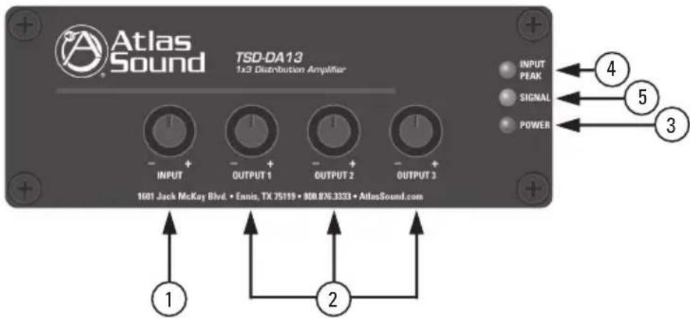
- Input Level Control - Adjusts the gain of the source audio signal that is applied to the DA13 circuitry. Turn clockwise to increase the signal level and counter-clockwise to decrease it.
Note: The Input Level Control knob can be removed and replaced with a supplied security cover to prevent unauthorized adjustment. - Output Level Controls - Adjust the level of each of the three outputs using these controls. Turn clockwise to increase the signal level and counter-clockwise to decrease it. Note: The output level control knobs can be removed and replaced with supplied security covers to prevent unauthorized adjustment.
- Power LED - Illuminates BLUE when 24VDC power is present.
- Input Peak LED - Illuminates Red when the input signal reaches 3dBV below when signal clipping will occur. Occasional flashing is normal but if this indicator is continuously On, then reduce the input level using the input level control on the front panel.
- Signal LED - Illuminates Green when the input signal strength reaches 25mV to verify a signal path.

Atlas

1601 Jack McKay Blvd. • Ennis, Texas 75119 U.S.A.
Telephone: 800.876.3333 • Fax: 800.765.3435
AtlasIED.com - 3 -
Rear Panel Description
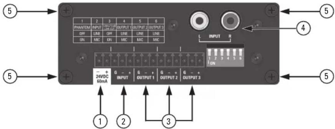
TSD Input/Output connections are removable for easy system wiring. The connector has a 3.5mm pitch between pins.
- DC Power Input - Each TSD that requires DC power comes with a 2 position connector for an external 24VDC power supply (sold separately). Because of the TSD's low power consumption, a single external power supply may power more than one TSD. Please refer to the specifications on current requirements in milliamps to match with the appropriate power supply. Note: It is acceptable to exceed the current requirements of the TSDs but NOT safe to use a power supply that is below the current requirement of the device.
- Mic/Line Input - Balanced Line level or balanced mic level signals are connected to this input. Your source connects to a balanced line or mic level source. Your connection must be mated properly to the input connector or signal loss and/or noise may occur. For gain or source input type selection, refer to the "Dip Switch Function Identification" chart for proper input setting. Note: Unbalanced line level inputs can be inserted with proper wire configuration by connecting the (G) and (-) terminals together.
- Mic/Line Output - Balanced Line level signals provide output when an input signal is present for connection to balanced mic or line level devices. Your output connections must be connected properly to the connectors or loss and/or noise may be introduced into the signal.
Note: Unbalanced line level devices can be used with proper wire configuration by connecting the (G) and (-) terminals together.
- RCA Input - Unbalanced audio signals applied to these female RCA connectors are electronically summed and fed to the three outputs. It is NOT recommended to use the unbalanced RCA inputs and the balanced input at the same time.
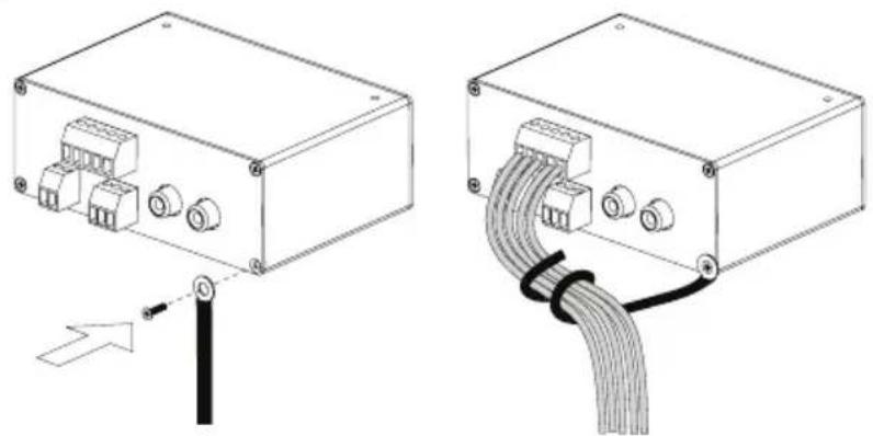
- Cable Management Retainer Points - Each TSD includes two cable retainer straps for securing the included cable management retainers. Remove one of the rear panel screws, align the panel hole with a retainer and firmly tighten the screws.

1601 Jack McKay Blvd. • Ennis, Texas 75119 U.S.A. Telephone: 800.876.3333 • Fax: 800.765.3435
AtlasIED.com - 4 -
Dip Switch Function Identification
SWITCH FUNCTIONS
| 1 | 2 | 3 | 4 | 5 | 6 |
| PHANTOM | INPUT | 125 × 10^12 B LOW CUT | OUTPUT 1 | OUTPUT 2 | OUTPUT 3 |
| OFF | LINE | OFF | LINE | LINE | LINE |
| ON | MIC | ON | MIC | MIC | MIC |
Switch Position
- DIP SW # 1 - 24VDC Phantom Power applies power to the input terminal for condenser mic operation. Down position is On.
- DIP SW # 2 - Input Mic or Line Select for input gain selection. Up position is Line, down position is Microphone.
- DIP SW #3 - Input Low Cut Filter engages at a roll off rate of 12dB per octave. This filter operates either in the Line or Mic mode. Ideal for vocal microphones to reduce low frequency energy and to increase intelligibility. Down position is On.
- DIP SW # 4,5,6 - Microphone or Line signal level selection for each output. Up position is Line, down position is Microphone.
Cable Management
natural_image
Technical line drawing of an electronic device showing internal components and cable termination (no text or symbols)Knob and Security Cover
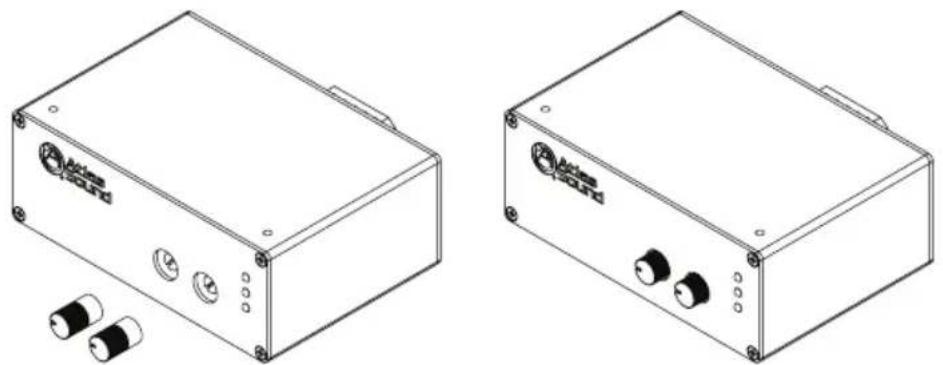
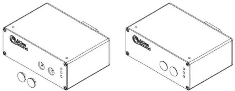
All front panel level controls feature a removable knob that can be replaced with an included security cover. Follow these steps to prevent potentiometer damage or unwanted changes.
- Knob Installation - Turn the potentiometer shaft fully counter-clockwise. Align the knob indicator to the lowest setting on the panel and the potentiometer shaft slot. Carefully press the knob onto the potentiometer shaft. Do not force or damage may occur to the potentiometer.
natural_image
Technical line drawings of two electronic device modules with buttons and connectors (no text or symbols)- Security Cover Installation - Remove the knob from the panel and insert the cover. Small pliers may be required to remove the knobs. Align the security cover to the level control panel hole. Push the cover into the hole until it snaps into place. Do not force or damage may occur to the potentiometer.
natural_image
Two technical line drawings of an electronic device casing with buttons and mounting holes (no text or symbols)
1601 Jack McKay Blvd. • Ennis, Texas 75119 U.S.A. Telephone: 800.876.3333 • Fax: 800.765.3435
Mounting
Listed below are the ways to mount the TSD and the optional accessories that can be purchased.
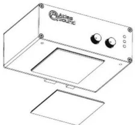
- Velcro™ - Each unit includes two 2" x 2" pieces of industrial-grade Velcro™ with adhesive backing to adhere to any flat surface. Clean all surfaces before applying the adhesive side of the Velcro™.
natural_image
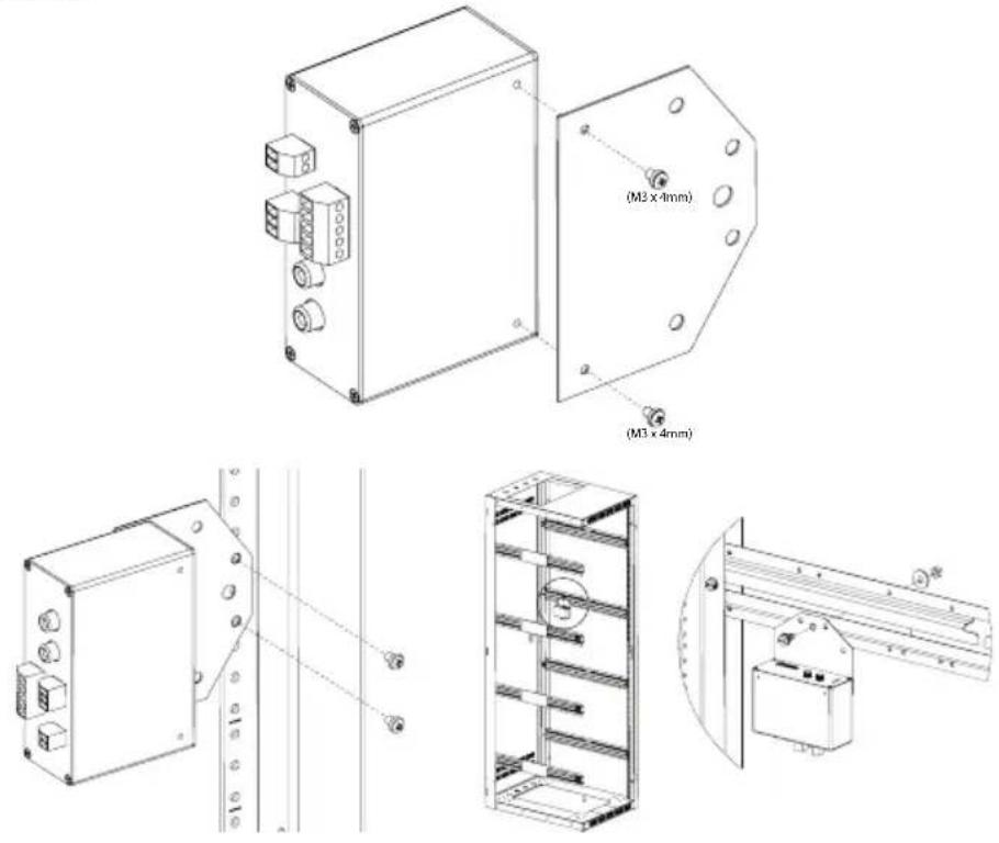
Line drawing of a device casing with labeled buttons and mounting base (no text or symbols)- Multi Mount Plate - Each TSD includes a versatile multi-position mounting plate. This plate allows the TSD to be mounted to any surface; but is ideal for use with rear rack rails or side rack hat channels. Use the included M3 x 4mm screws to install the plate on the TSD. Note: Only use the included M3 x 4mm screws as other screws may be too long and will cause internal damage to the TSD. The multi-position mounting plate is a new addition being included with TSDs. If the TSD being used did not include the mounting plate, contact AtlasIED customer service at 1-800-876-3333.

1601 Jack McKay Blvd. • Ennis, Texas 75119 U.S.A. Telephone: 800.876.3333 • Fax: 800.765.3435
AtlasIED.com - 7 -
Optional Mounting Accessories
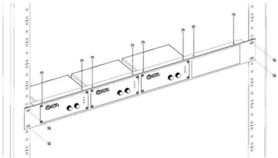
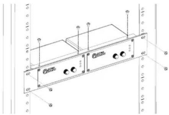
- TSD-RMK 19" Width Rack Mount Kit - For 19" rack mounting, AtlasIED offers an optional rack mount kit, the TSD-RMK. This rack mount kit can support up to four TSD units. The kit includes three blank panels designed to fill any unused slots. Use the included hardware to mount the TSD into the rack mount kit using the top mount screw holes on the TSD.
natural_image
Technical line drawing of a server rack with multiple ports and connectors (no text or symbols)- TSD-RMKHR Half Width Rack Mount Kit - AtlasIED offers an optional rack mount kit that can be used in half width rack applications including the AtlasIED WMA-HR and AWR-HR models. The TSD-RMKHR can support up to two TSDs. Included is an extra blank panel to fill one of the spaces if only one TSD is being used.
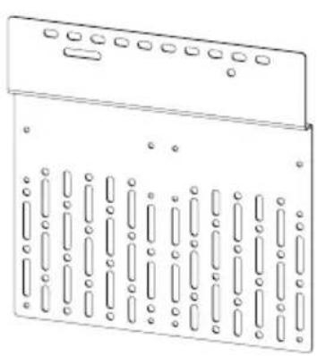
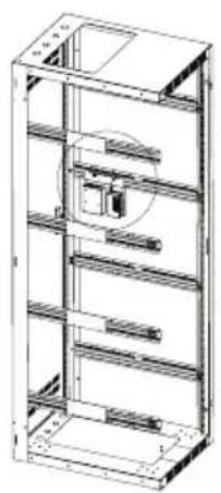
- TSD-RRMK Rear Rack Mounting Kit - For complete flexibility in mounting a TSD or TSD external power supplies the optional TSD-RRMK is available. The TSD-RRMK can support mounting of either two larger TSDs with external power supplies or up to 4 TSD models. Note: Only use the included M3 x 4mm screws as other screws may be too long and will cause internal damage to the TSD.
natural_image
Technical line drawing of a mechanical component with multiple slots and mounting holes (no text or symbols)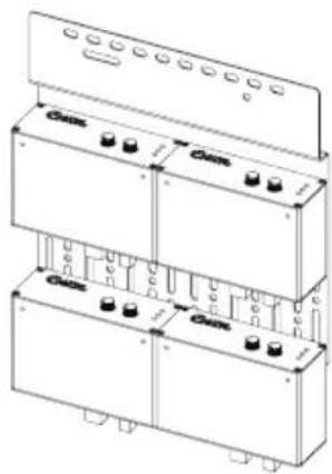
natural_image
Technical line drawing of a multi-level industrial shelving unit (no text or symbols)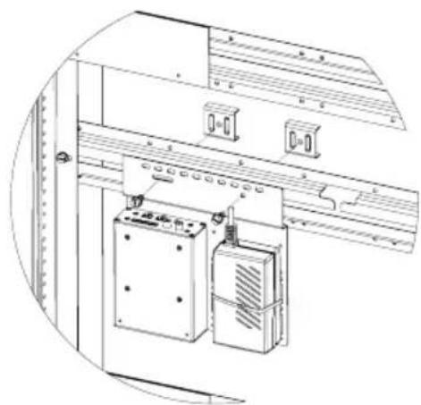
natural_image
Technical line drawing of an electrical cabinet with control panel and door holders (no text or symbols)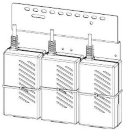
natural_image
Technical line drawing of three identical electrical enclosure units with heat sinks and ventilation grilles (no text or symbols)
Atlas
IED.川
1601 Jack McKay Blvd. • Ennis, Texas 75119 U.S.A.
Telephone: 800.876.3333 • Fax: 800.765.3435
AtlasIED.com - 9 -
Block Diagram
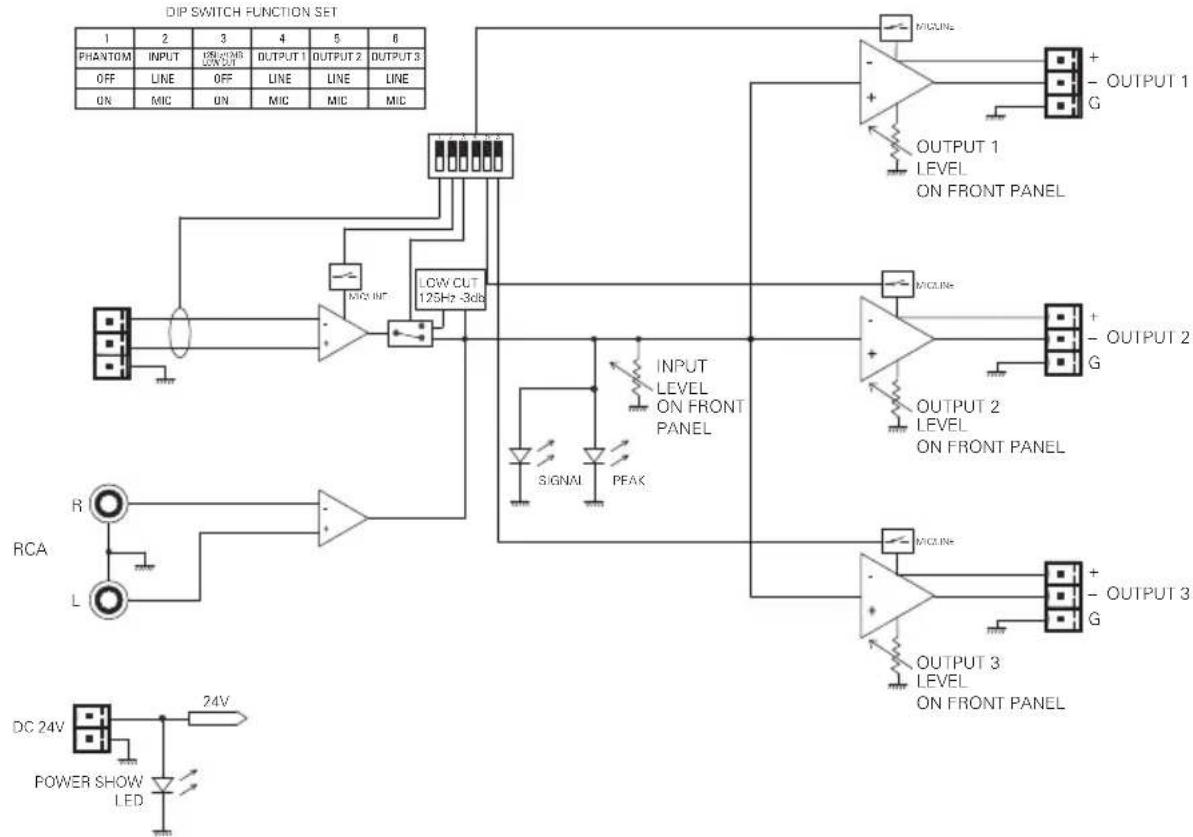
flowchart
graph TD
    A["PHANTOM INPUT"] --> B["INCHING OUTPUT"]
    B --> C["OUTPUT 1 OUTPUT 2 OUTPUT 3"]
    D["OFF LINE ON MIC"] --> E["OFF LINE MIC"]
    F["LINE ON MIC"] --> G["LINE ON MIC"]
    H["LINE ON MIC"] --> I["LINE ON MIC"]
    J["LINE ON MIC"] --> K["LINE ON MIC"]
    L["LOW CUT 125Hz -3dB"] --> M["MICURE"]
    N["SIGNAL PEAK"] --> O["INPUT LEVEL ON FRONT PANEL"]
    P["OUTPUT 1 LEVEL ON FRONT PANEL"] --> Q["MICURE"]
    R["OUTPUT 2 LEVEL ON FRONT PANEL"] --> S["MICURE"]
    T["OUTPUT 3 LEVEL ON FRONT PANEL"] --> U["MICURE"]
    V["RCA"] --> W["L"]
    X["DC 24V POWER SHOW LED"] --> Y["24V"]
    Z["OUTPUT 1 G OUTPUT 2 G"] --> AA["+ OUTPUT 1 G"]
    AB["INPUT LEVEL ON FRONT PANEL"] --> AC["+ OUTPUT 2 G"]
    AD["OUTPUT 3 LEVEL ON FRONT PANEL"] --> AE["+ OUTPUT 3 G"]
Specifications
Description 1 x 3 Mic/Line Distribution Amplifier
Chassis Color Black
Chassis Material Aluminum
Inputs
Type Qty 1, Unbalanced
Connection RCA Left and Right Actively Summed
Impedance 10KΩ
Input Level 316mV (-10dBV) = 2V (+6dBV) Balanced Output,
Maximum Input 6V (15dBV)
Type Qty 1, Balanced Mic or Line Selectable
Connection Removable 3 Position Captive Screw 3.5mm Spacing
Impedance 1.2KΩ Balanced, 600Ω Unbalanced
Phantom 24VDC Defeatable
Low Cut Filter 125Hz/12dB Defeatable
Line Input Level 1V (0dBV) Balanced = 2V (+6dBV) Balanced Output,
Maximum Input 6V (15dBV)
Mic Input Level 46dB Gain 10mV (-40dBV) Balanced = 2V (+6dBV) Balanced Output,
Maximum Input 40mV (-27dBV)

Atlas
IED.川
1601 Jack McKay Blvd. • Ennis, Texas 75119 U.S.A.
Telephone: 800.876.3333 • Fax: 800.765.3435
AtlasIED.com - 10 -
Outputs
Type Qty 3, Balanced Mic or Line Selectable
Connection Removable 3 Position Captive Screw 3.5mm Spacing
Impedance 300Ω Balanced, 150Ω Unbalanced
Line Output Level 1V (0dBV) In = 2V (+6dBV) Balanced, Maximum Output 6V (15dBV)
Mic Input vs Output Level 10mV (-40dBV) In = 80mV (-21dBV), Maximum Output 300mV(-10dBV)
Controls
Input Level Control Qty 1, Removable Knob with Security Cover
Output Level Control Qty 3, Removable Knobs with Security Covers
Dip Switch Function • Phantom Power 24VDC
- Input Mic/Line Select
- Input 125Hz/12dB High Pass Filter
• Output Qty 3, Mic/Line Select
Indicators
Output Signal Green, 25mV On Threshold
Output Peak Red, -3dB Before Clip
Power Blue
Electrical
Frequency Response 20Hz - 20kHz (±1dB)
THD .06% & 1kHz
Signal to Noise Line to Line: 85dBV
Mic to Line: 78dBV
Line to Mic: 55dBV
Mic to Mic: 55dBV
Power Requirements
Voltage 24VDC
Power Consumption 60mA
Power Consumption 1.4W
Dimensions H 1.5" (39mm) x W 4" (101mm) x D 2.75" (70mm)
Weight 6oz, .165kg
Included Accessories
Velcro™ Industrial-Grade
Multi-Mount Plate Qty 1, Includes Two (2) M3 x 4mm Screws
Cable Retainers Qty 2
Level Control Knobs Qty 4
Level Control Security Covers Qty 4
Optional Accessories
TSD 24VDC Power Supply
TSD-RMK 1 RU 19" Width Rack Mount Panel (Supports 4 TSD Units)
TSD-RMKHR 1 RU Half Rack Width Panel (Supports 2 TSD Units)
TSD-RRMK Rear Rack Mounting Kit
Safety and Certifications
External Power Supply cUL, CE, RoHS, TUV

1601 Jack McKay Blvd. • Ennis, Texas 75119 U.S.A.
Telephone: 800.876.3333 • Fax: 800.765.3435
AtlasIED.com - 11 -
Limited Warranty
All products manufactured by AtlasIED are warranted to the original dealer/installer, industrial or commercial purchaser to be free from defects in material and workmanship and to be in compliance with our published specifications, if any. This warranty shall extend from the date of purchase for a period of three years on all AtlasIED products, including SOUNDOLIER brand, and ATLAS SOUND brand products except as follows: one year on electronics and control systems; one year on replacement parts; and one year on Musician Series stands and related accessories. Additionally, fuses and lamps carry no warranty. AtlasIED will solely at its discretion, replace at no charge or repair free of charge defective parts or products when the product has been applied and used in accordance with our published operation and installation instructions. We will not be responsible for defects caused by improper storage, misuse (including failure to provide reasonable and necessary maintenance), accident, abnormal atmospheres, water immersion, lightning discharge, or malfunctions when products have been modified or operated in excess of rated power, altered, serviced or installed in other than a workman like manner. The original sales invoice should be retained as evidence of purchase under the terms of this warranty. All warranty returns must comply with our returns policy set forth below. When products returned to AtlasIED do not qualify for repair or replacement under our warranty, repairs may be performed at prevailing costs for material and labor unless there is included with the returned product(s) a written request for an estimate of repair costs before any nonwarranty work is performed. In the event of replacement or upon completion of repairs, return shipment will be made with the transportation charges collect.
EXCEPT TO THE EXTENT THAT APPLICABLE LAW PREVENTS THE LIMITATION OF CONSEQUENTIAL DAMAGES FOR PERSONAL INJURY, ATLASIED SHALL NOT BE LIABLE IN TORT OR CONTRACT FOR ANY DIRECT, CONSEQUENTIAL OR INCIDENTAL LOSS OR DAMAGE ARISING OUT OF THE INSTALLATION, USE OR INABILITY TO USE THE PRODUCTS. THE ABOVE WARRANTY IS IN LIEU OF ALL OTHER WARRANTIES INCLUDING BUT NOT LIMITED TO WARRANTIES OF MERCHANTABILITY AND FITNESS FOR A PARTICULAR PURPOSE.
AtlasIED does not assume, or does it authorize any other person to assume or extend on its behalf, any other warranty, obligation, or liability. This warranty gives you specific legal rights and you may have other rights which vary from state to state.
Service
Should your Atlas TSD require service, please contact the AtlasIED warranty department at 1-877-689-8055, ext. 277 to obtain an RA number.
AtlasIED Tech Support can be reached at 1-800-876-3333 or support.atlasied.com.
Visit our website at www.AtlasIED.com to see other Atlas products.
©2017 Atlas Sound L.P. The Atlas "Circle A", Soundolier, and Atlas Sound are trademarks of Atlas Sound L.P.
IED is a registered trademark of Innovative Electronic Designs LLC. All Rights Reserved.
All other trademarks are the property of their respective owners. All specs are subject to change without notice. ATS003936 RevB 4/17

1601 Jack McKay Blvd. • Ennis, Texas 75119 U.S.A.
Telephone: 800.876.3333 • Fax: 800.765.3435
AtlasIED.com - 12 -
- Features
- Audio Applications
- Installation
- Front Panel Description
- Dip Switch Function Identification
- Switch Position
- Cable Management
- Knob and Security Cover
- Mounting
- Optional Mounting Accessories
- Specifications
- Inputs
- Outputs
- Controls
- Indicators
- Electrical
- Power Requirements
- Included Accessories
- Optional Accessories
- Safety and Certifications
- Limited Warranty
- Service
Brand : Atlas Sound
Model : TSD-DA13
Category : Hi-Fi System