BlueBridge BB-SM1 - Hi-Fi System Atlas Sound - Free user manual and instructions
Find the device manual for free BlueBridge BB-SM1 Atlas Sound in PDF.


| Product Type | Site Manager / Controller for BlueBridge Audio Systems |
| Manufacturer | Atlas Sound |
| Model | BlueBridge BB-SM1 |
| Dimensions (est.) | 4.5 x 4.5 x 1.5 in (approx.) |
| Weight (est.) | 0.5 lb (approx.) |
| Power Supply | Power over Ethernet (PoE) IEEE 802.3af |
| Network Interface | 10/100 Ethernet, LAN/Wi-Fi (via network) |
| Control Protocols | TCP, UDP, RS232 |
| Main Functions | Web Interface, 3rd Party Control Management, System Scheduler, Master Project Backup |
| Software Compatibility | BlueBridge Designer software |
| Compatible Devices | BlueBridge DSP processors (e.g., BB-88-1) |
| Web Browser Control | Supports PC, tablet, smartphone, iOS/Android devices |
| 3rd Party Integration | Crestron, AMX, etc., via Ethernet or RS232 |
| Scheduling | Preset-based events with recurring options |
| Backup Storage | Stores site files and parameters on device |
| Operating Temperature | 0°C to 40°C (est.) |
| Enclosure Material | Metal (est.) |
| User Interface | Web-based control pages, customizable |
| Password Protection | Yes, for web panels and device |
| Firmware Upgrade | Via Network View in Designer software |
| Warranty | 1 year on electronics and control systems |
| Maintenance | No user-serviceable parts; professional service required |
| Safety | Follow local electrical codes; use PoE switch |
Frequently Asked Questions - BlueBridge BB-SM1 Atlas Sound
Note: Recommended browsers are Google Chrome or Apple Safari.
User questions about BlueBridge BB-SM1 Atlas Sound
0 question about this device. Answer the ones you know or ask your own.
Ask a new question about this device
Download the instructions for your Hi-Fi System in PDF format for free! Find your manual BlueBridge BB-SM1 - Atlas Sound and take your electronic device back in hand. On this page are published all the documents necessary for the use of your device. BlueBridge BB-SM1 by Atlas Sound.
USER MANUAL BlueBridge BB-SM1 Atlas Sound
natural_image
Abstract black-and-white logo design featuring a stylized letter 'A' with a circular element and a dot, no text or symbols present.Atlas Sound

BB-SM1 Reference Guide
BlueBridge® Site Manager, BB-SM1, Reference Guide
This reference guide is designed to familiarize system designers with all the integrated functions of the BB-SM1. This guide will outline the steps necessary to complete a system design incorporating the BB-SM1 in a BlueBridge® Designer software design file and enabling the hardware on the network.
The BB-SM1 serves four main functions.
- The BB-SM1 will serve as a Web Interface for custom control over the BlueBridge ^ audio system. This includes controlling the audio system from computers, tablet PCs, smart phones, iOS ^ devices, and/or any device that has a web browser and can be on the same network with the BlueBridge ^ Audio System. (This includes LAN or Wi-Fi.)
- The BB-SM1 simplifies 3rd party control (Crestron, AMX, Etc.) in BlueBridge® system designs, using either Ethernet or RS232. (Crestron modules and documentation are available on the Atlas website at http://www.atlassound.com/BlueBridge)
• The BB-SM1 can function as a system wide scheduler. - The BB-SM1 can serve as a Master Project Backup and Design File Storage device.
Designing with a BB-SM1
The BB-SM1 can be incorporated into any Blueprint design by dragging the BB-SM1 module from the system components library onto the blueprint system design.
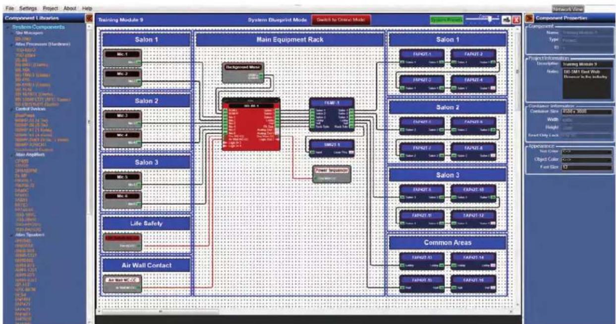
In (Fig 1) a design file has been completed and a BB-SM1 has been incorporated into the design.
Note: The internal audio system design of the DSP hardware must be complete (or near completion) before a BB-SM1 can be configured.
flowchart
graph TD
    subgraph Main Equipment Rack
        A["Main Equipment Rack"]
        B["Salon 1"]
        C["Salon 2"]
        D["Salon 3"]
        E["Salon 4"]
        F["Salon 5"]
        G["Salon 6"]
        H["Salon 7"]
        I["Salon 8"]
        J["Salon 9"]
    end

    subgraph System Blueprint Mode
        K["Background Mode"]
        L["FAMP 1"]
        M["SME2T 1"]
        N["Power Inverter"]
    end

    subgraph Component Properties
        O["Component Name: Training Module 9"]
        P["Component Type: Process"]
    end

    A --> Q["Main Equipment Rack"]
    C --> Q
    D --> Q
    E --> Q
    F --> Q
    G --> Q
    H --> Q
    I --> Q
    J --> Q
    K --> Q
    L --> Q
    M --> Q
    N --> Q
    O --> Q
    P --> Q
    Q --> R["Salon 1"]
    Q --> S["Salon 2"]
    Q --> T["Salon 3"]
    Q --> U["Salon 4"]
    Q --> V["Salon 5"]
    Q --> W["Salon 6"]
    Q --> X["Salon 7"]
    Q --> Y["Salon 8"]
    Q --> Z["Salon 9"]
    Q --> AA["Salon 10"]
    Q --> AB["Salon 11"]
    Q --> AC["Salon 12"]
    Q --> AD["Salon 13"]
    Q --> AE["Salon 14"]
    Q --> AF["Salon 15"]
    Q --> AG["Salon 16"]
    Q --> AH["Salon 17"]
    Q --> AI["Salon 18"]
    Q --> AJ["Salon 19"]
    Q --> AK["Salon 20"]
    Q --> AL["Salon 21"]
    Q --> AM["Salon 22"]
    Q --> AN["Salon 23"]
    Q --> AO["Salon 24"]
    Q --> AP["Salon 25"]
    Q --> AQ["Salon 26"]
    Q --> AR["Salon 27"]
    Q --> AS["Salon 28"]
    Q --> AT["Salon 29"]
    Q --> AU["Salon 30"]
    Q --> AV["Salon 31"]
    Q --> AW["Salon 32"]
    Q --> AX["Salon 33"]
    Q --> AY["Salon 34"]
    Q --> AZ["Salon 35"]
    Q --> BA["Salon 36"]
    Q --> BB["Salon 37"]
    Q --> BC["Salon 38"]
    Q --> BD["Salon 39"]
    Q --> BE["Salon 40"]
    Q --> BF["Salon 41"]
    Q --> BG["Salon 42"]
    Q --> BH["Salon 43"]
    Q --> BI["Salon 44"]
    Q --> BJ["Salon 45"]
    Q --> BK["Salon 46"]
    Q --> BL["Salon 47"]
    Q --> BM["Salon 48"]
    Q --> BN["Salon 49"]
    Q --> BO["Salon 50"]
Figure 1
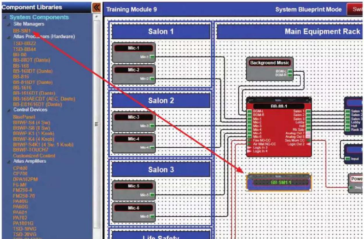
In the Component Libraries Pane, under System Components/Site Managers (Fig 2), select (left mouse click and hold) the BB-SM1 and drag the module onto the design grid. (Fig. 2.1)
Please note that this can only be done in the System BluePrint mode.
If the Site Manager is not listed in the Library, left click on the design grid to bring up the correct menu items specific to that grid.
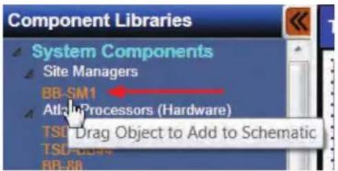
Figure 2
flowchart
graph TD
    subgraph System Components
        A["Salon 1"] --> B["Main Equipment Rack"]
        C["Salon 2"] --> B
        D["Salon 3"] --> B
        E["Salon 4"] --> B
        F["Salon 5"] --> B
        G["Salon 6"] --> B
    end

    subgraph Control Devices
        H["Control Devices"]
        I["Control Devices"]
        J["Control Devices"]
        K["Control Devices"]
        L["Control Devices"]
    end

    style System Components fill:#f9f,stroke:#333
    style Control Devices fill:#ccf,stroke:#333

    subgraph Training Module 9
        M["Salon 1"] --> N["Main Equipment Rack"]
        O["Salon 2"] --> N
        P["Salon 3"] --> N
        Q["Salon 4"] --> N
        R["Salon 5"] --> N
        S["Salon 6"] --> N

    end

    style System Components fill:#f9f,stroke:#333
    style Control Devices fill:#ccf,stroke:#333

    style Training Module 9 fill:#dfd,stroke:#333
    style System Blueprint Mode fill:#dfd,stroke:#333
Figure 2.1
The BB-SM1 has four main functions, Web Interface, Third Party Control Management, and System Scheduler each can be found in the right click menu of the module (Fig 3). The Master Project Backup functions are located in the File and Project menus.
Working with the Web Interface
Select the Web Interface as shown in Fig 3 and the design grid window will open. (Fig 4) The web interface will also open if the BB-SM1 module is double left clicked. (it is the default interface)
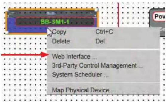
Figure 3
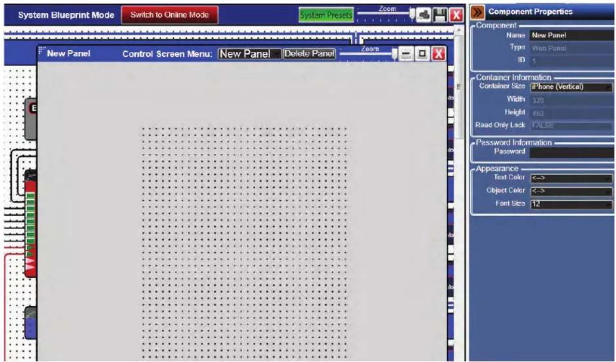
Figure 4
What is designed on this grid system will be the custom user control pages accessible via a web browser enabled device (PC, Tablet, Android, Smart Phone, iOS device, etc.). The control panel can be a single page of controls or several pages. The process of configuring these panels is the same as configuring the BB-TOUCH7 or a BluePanel.
When it is necessary to work with several control panels, Atlas recommends labeling each panel with a unique name. This is done in the Component Properties Pane on the right side window in the designer software (Fig 5). In the example the Name has been changed to Page-1.
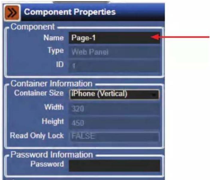
Figure 5
The size of the grid can be changed to easily accommodate different control devices, including a custom size where any screen resolution can be entered up to 5000x5000.
In the example an iPhone ^® in a vertical orientation will be used for the panel. (Fig 6)
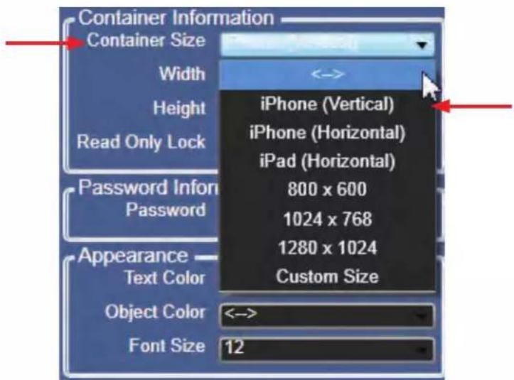
Figure 6
If needed, a panel can be password protected. (Fig 7)
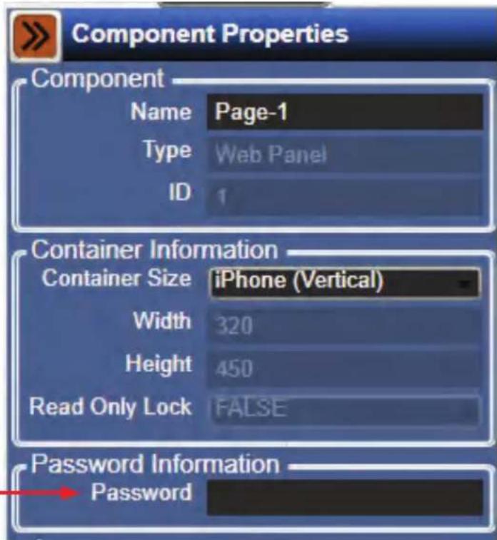
Figure 7
To add a panel to the design, select the drop down menu at the top of the web interface design grid window. Select "Add New Panel". (Fig 8)
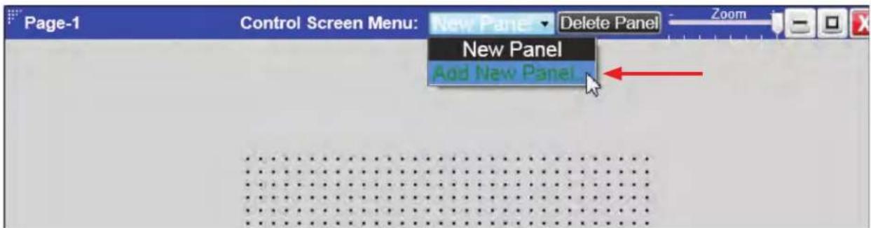
Figure 8
A pop-up window will ask for a new name for the panel. (Fig 8.1)
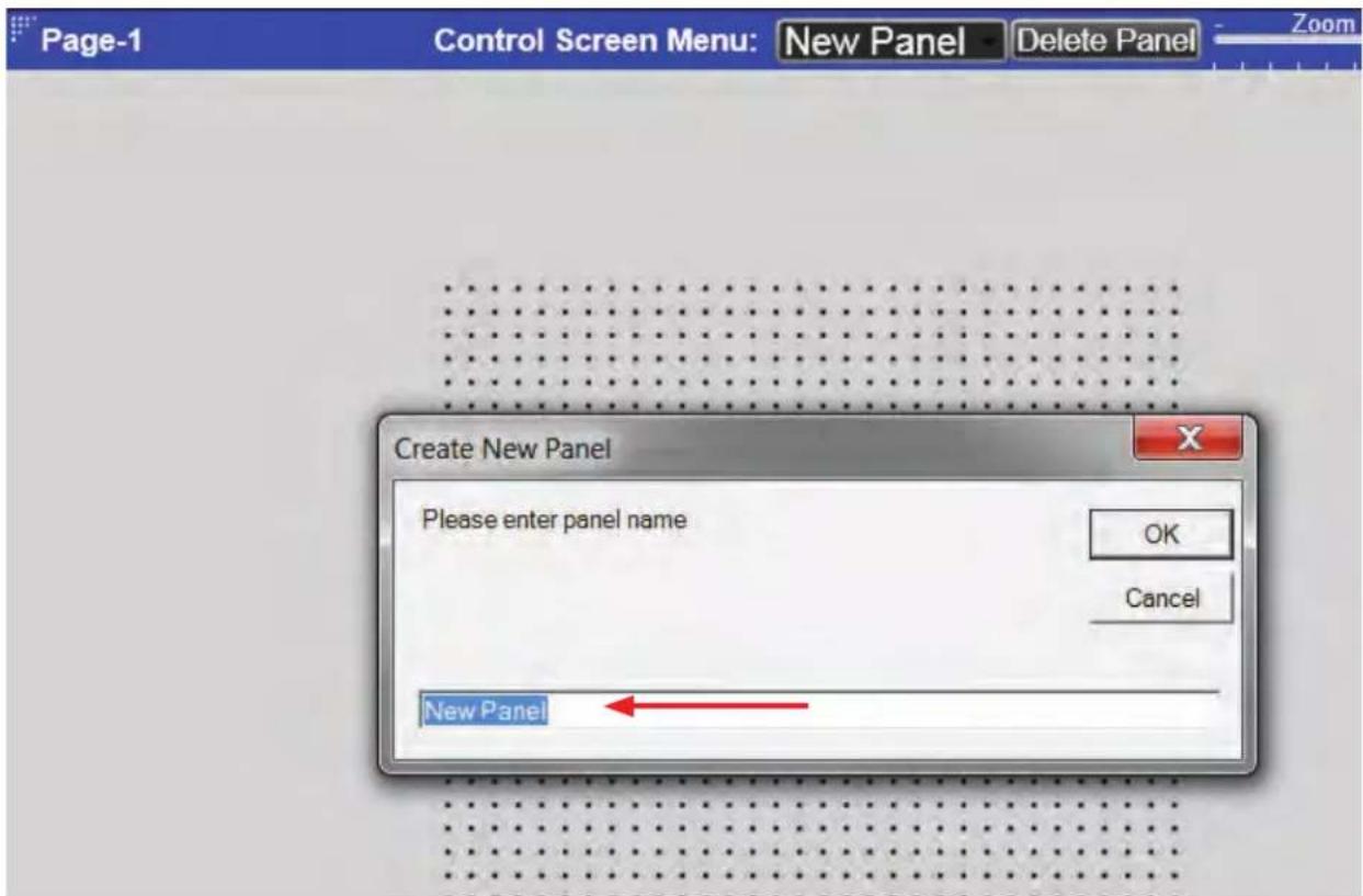
Figure 8.1
Type in a name and select OK. (Fig 8.2)
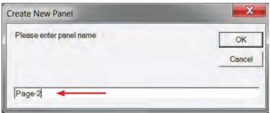
Figure 8.2
A new panel will be generated and accessible for configuration from the drop down menu. (Fig 8)
Panel Control Elements
In the Component Libraries Pane the "Panel Control Components" will appear by left clicking on the design grid for the web interface. (Fig 9)
In this library there are four design elements that can be used for creating a unique control page or a series of control pages that can be accessed via a web browser. The four elements are:
- Control Page Button - This allows the designer to put a button on the control page that will allow a user to navigate to other control pages. These other pages can be password protected if necessary.
- Label - This allows a designer to put a name or set of instructions into any part of a control page.
- Image - This allows a designer to import a PNG image file into a control page.
- Note: The PNG file is not stored in the design file and will have to be available for anyone needing to do work online with the design file.
- Rectangle - This is a container tool that is used as a graphic element to separate sections of a control page.
To add a control page button into the design, left click and hold on the "Control Page Button" text in the library. (Fig 9) Drag and drop onto the design grid. (Fig 10)
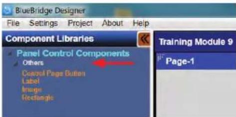
Figure 9
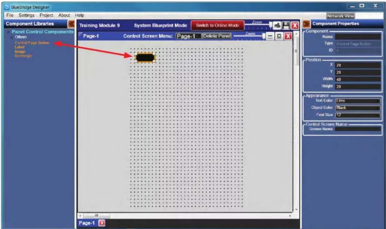
Figure 10
Once this is complete, the button can be set-up in the Component Properties Pane. A name can be entered in the Component box that will be displayed on the button itself. The appearance of the button can be changed including text color, font size, and background color. Note: The button must be associated with another control page. This is completed in the "Control Screen Name" box. When entering a screen name it must exactly match the name of the control page that it will be associated with. (Fig 10.1 and 10.2)
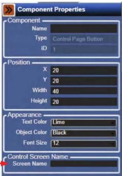
Figure 10.1
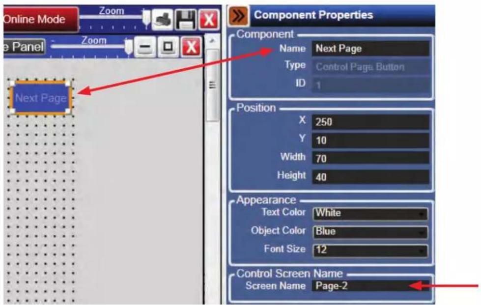
Figure 10.2

Atlas Sound
1601 Jack McKay Blvd. • Ennis, Texas 75119 U.S.A.
Telephone: 800.876.3333 • Fax: 800.765.3435
To add a Label into the design, left click and hold on the "Label" text in the library. Drag and drop onto the design grid. The Label will appear as a Black Box when dropped on the grid. (Fig 11)
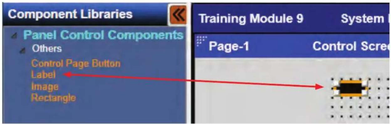
Figure 11
When the label is on the design grid, it is now possible to give it a unique name, change font size and color, or change background color. These tasks are done in the Component Properties Pane. (Fig 11.1)
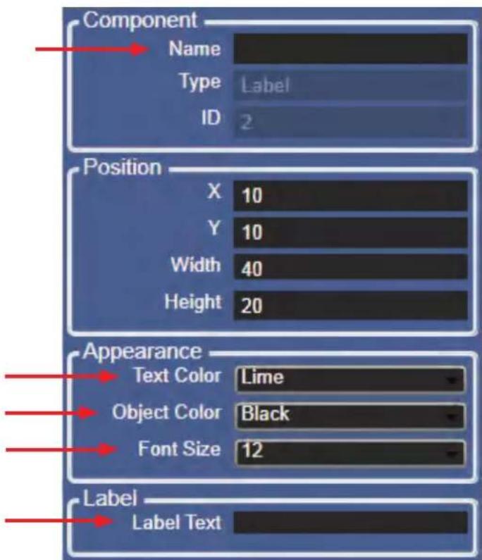
Figure 11.1
The size of the label can be changed by left clicking and holding a corner of the label, then dragging the corner to the desired size. Alternately, the label can be sized by changing values in the Position box of the Component Properties Pane. (Fig 12)
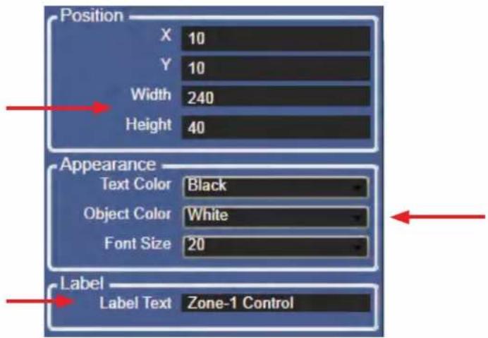
Figure 12
The changes done in Fig 12 can be seen in Fig 12.1.
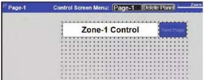
Figure 12.1
Add an image into the design by left clicking and holding on the "Image" text in the library. Drag and drop onto the design grid. An image placeholder will appear on the design grid as a white box with a question mark. (Fig 13)
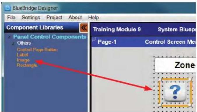
Figure 13

Atlas Sound
1601 Jack McKay Blvd. • Ennis, Texas 75119 U.S.A.
Telephone: 800.876.3333 • Fax: 800.765.3435
At this time an image file can be loaded into that position and resized as needed.
The image file must be in a PNG format. Add the PNG image file by clicking on the select box in the Component Properties Pane under "Object Image". (Fig 14)
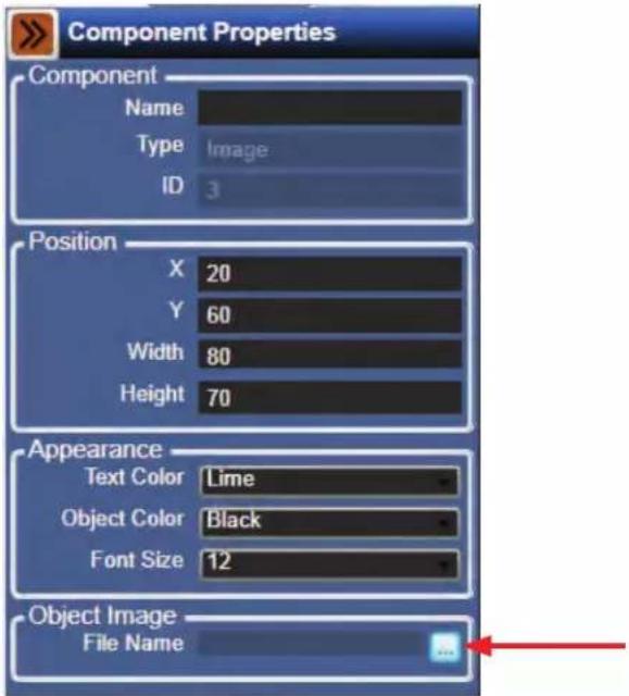
Figure 14
A window will open allowing the designer to navigate to the PNG image file stored on the computer. In the example the file is located and the Atlas Sound logo is selected. (Fig 15)
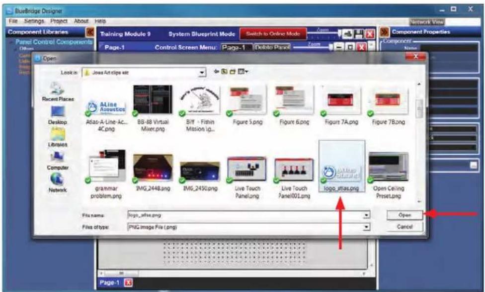
Figure 15
Click on the Open button and the image will replace the question mark placeholder. (Fig 15.1)
The image can be resized by left clicking and holding a corner of the image, then dragging the corner to the desired size. The image can also be sized by changing values in the Position box in the Component Properties Pane in the same way as a label. (Fig 16)
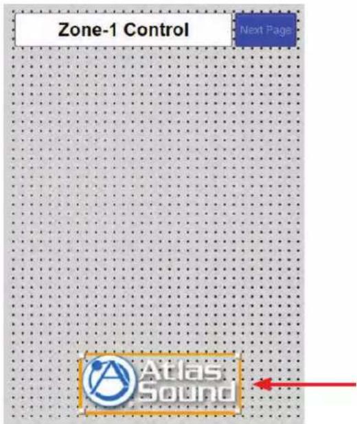
Figure 15.1
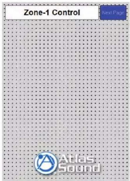
Figure 16
The image file can be used as a background if desired and lay control elements over the top of the image. When this is needed, right click the image and select "Send to Back". (Fig 16.1)
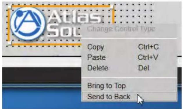
Figure 16.1
Add a Rectangle into the design by left clicking and holding on the "Rectangle" text in the Component Library. Drag and drop onto the design grid. The rectangle will appear as a yellow outline when dropped on the grid. (Fig 17)
A rectangle is a great tool for creating separation between control elements.
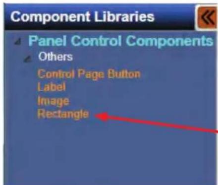
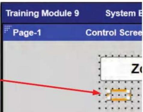
Figure 17
Using the Component Properties pane the rectangle can be resized, object color can be changed, and line thickness can be adjusted. (Fig 18)
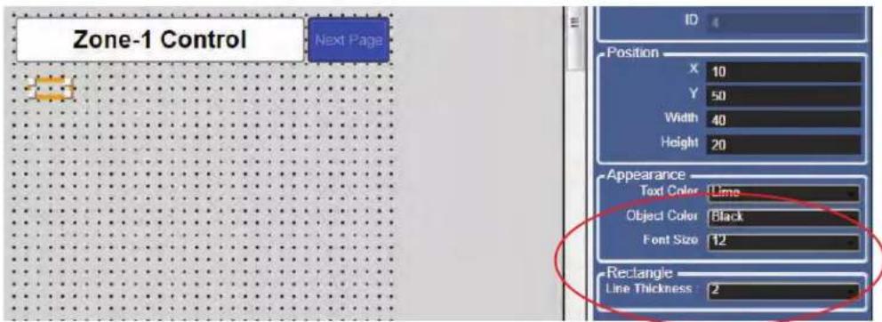
Figure 18
Adding Control Elements
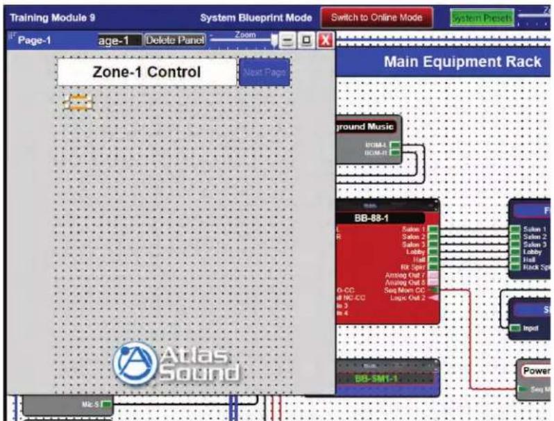
Adding control elements is as easy as dragging in any fader, button, meter, etc. from a DSP module into the design file and dropping it on to the Web Interface design grid.
flowchart
graph TD
    A["Main Equipment Rack"] --> B["BB-88-1"]
    B --> C["Power"]
    B --> D["BB-SM1-1"]
    D --> E["Main Equipment Rack"]
    style A fill:#f9f,stroke:#333
    style B fill:#ccf,stroke:#333
    style C fill:#cfc,stroke:#333
    style D fill:#fcc,stroke:#333
    subgraph Main Equipment Rack
        F["Ground Music"]
        G["BB-88-1"]
        H["Power"]
    end
Figure 19
To bring in a control element open the DSP module by double clicking on the module.
Selecting the tile function button allows easy navigation between the web control grid and the DSP design file. Select the tile function button at the top right of the design grid window. (Fig 19.1)
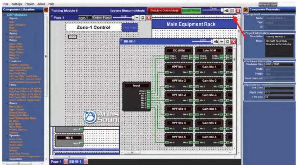
Figure 19.1

Atlas Sound
1601 Jack McKay Blvd. • Ennis, Texas 75119 U.S.A.
Telephone: 800.876.3333 • Fax: 800.765.3435
The windows will auto align side by side. (Fig 20)
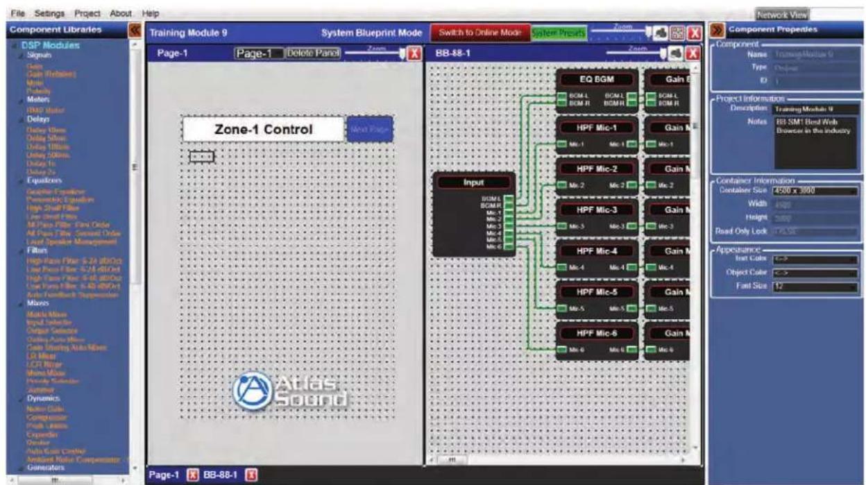
Figure 20
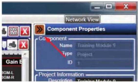
If more workspace is required, the Component Libraries and Component Properties panes can be minimized using the minimize arrow buttons. (Fig 21, 21.1)
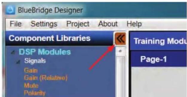
Figure 21 Figure 21.1
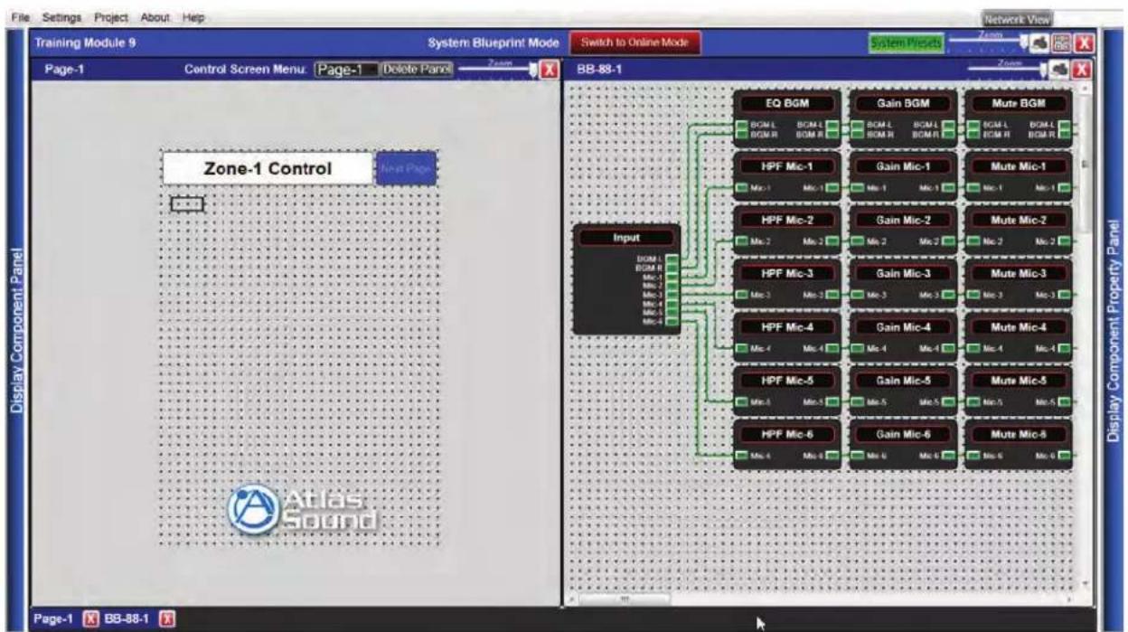
Select the Module inside the DSP that will be used on the control page. In this example the Gain Mic-1 will be used.
flowchart
graph TD
    A["Input"] --> B["EQ BGM"]
    A --> C["Gain BGM"]
    A --> D["Mute BGM"]
    B --> E["BCM L BGM R BGM R"]
    C --> F["BCM L BGM R BGM R"]
    D --> G["BCM L BGM R BGM R"]
    E --> H["HPF Mic-1"]
    E --> I["HPF Mic-2"]
    E --> J["HPF Mic-3"]
    E --> K["HPF Mic-4"]
    E --> L["HPF Mic-5"]
    E --> M["HPF Mic-6"]
    F --> N["Gain Mic-1"]
    F --> O["Gain Mic-2"]
    F --> P["Gain Mic-3"]
    F --> Q["Gain Mic-4"]
    F --> R["Gain Mic-5"]
    F --> S["Gain Mic-6"]
    G --> T["Mute Mic-1"]
    G --> U["Mute Mic-2"]
    G --> V["Mute Mic-3"]
    G --> W["Mute Mic-4"]
    G --> X["Mute Mic-5"]
    G --> Y["Mute Mic-6"]
    H --> Z["BCM L BGM R BGM R"]
    I --> AA["BCM L BGM R BGM R"]
    J --> AB["BCM L BGM R BGM R"]
    K --> AC["BCM L BGM R BGM R"]
    L --> AD["BCM L BGM R BGM R"]
    M --> AE["BCM L BGM R BGM R"]
    N --> AF["BCM L BGM R BGM R"]
    O --> AG["BCM L BGM R BGM R"]
    P --> AH["BCM L BGM R BGM R"]
    Q --> AI["BCM L BGM R BGM R"]
    R --> AJ["BCM L BGM R BGM R"]
    S --> AK["BCM L BGM R BGM R"]
    T --> AL["BCM L BGM R BGM R"]
    U --> AM["BCM L BGM R BGM R"]
    V --> AN["BCM L BGM R BGM R"]
    W --> AO["BCM L BGM R BGM R"]
    X --> AP["BCM L BGM R BGM R"]
    Y --> AQ["BCM L BGM R BGM R"]
    Z --> AR["BCM L BGM R BGM R"]
    AA --> AS["BCM L BGM R BGM R"]
    AB --> AT["BCM L BGM R BGM R"]
    AC --> AU["BCM L BGM R BGM R"]
    AD --> AV["BCM L BGM R BGM R"]
    AE --> AW["BCM L BGM R BGM R"]
    AF --> AX["BCM L BGM R BGM R"]
    AG --> AY["BCM L BGM R BGM R"]
    AH --> AZ["BCM L BGM R BGM R"]
    AI --> BA["BCM L BGM R BGM R"]
    AJ --> BB["BCM L BGM R BGM R"]
    AK --> BC["BCM L BGM R BGM R"]
    AL --> BD["BCM L BGM R BGM R"]
    AM --> BE["BCM L BGM R BGM R"]
    AN --> BF["BCM L BGM R BGM R"]
    AO --> BG["BCM L BGM R BGM R"]
    AP --> BH["BCM L BGM R BGM R"]
    AQ --> BI["BCM L BGM R BGM R"]
    AR --> BJ["BCM L BGM R BGM R"]
    AS --> BK["BCM L BGM R BGM R"]
    AT --> BL["BCM L BGM R BGM R"]
    AU --> BM["BCM L BGM R BGM R"]
    AV --> BN["BCM L BGM R BGM R"]
    AW --> BO["BCM L BGM R BGM R"]
    AX --> BP["BCM L BGM R BGM R"]
    AY --> BQ["BCM L BGM R BGM R"]
    AZ --> BR["BCM L BGM R BGM R"]
    BA --> BS["BCM L BGM R BGM R"]
    BB --> BT["BCM L BGM R BGM R"]
    BC --> BU["BCM L BGM R BGM R"]
    BD --> BV["BCM L BGM R BGM R"]
    BE --> BW["BCM L BGM R BGM R"]
    BF --> BX["BCM L BGM R BGM R"]
    BG --> BY["BCM L BGM R BGM R"]
    BH --> BZ["BCM L BGM R BGM R"]
    BI --> CA["BCM L BGM R BGM R"]
    BJ --> CB["BCM L BGM R BGM R"]
    BK --> CC["BCM L BGM R BGM R"]
    BL --> CD["BCM L BGM R BGM R"]
    BM --> CE["BCM L BGM R BGM R"]
    BN --> CF["BCM L BGM R BGM R"]
    BO --> CG["BCM L BGM R BGM R"]
    BP --> CH["BCM L BGM R BGM R"]
    CA --> CI["BCM L BGM R BGM R"]
Figure 22
Open the Module by double clicking the module. Once open, the Gain Fader will appear. (Fig 23)
At this point the control can be brought into a control page. Select the control to put it on the control page grid. This can be completed in one of two ways.
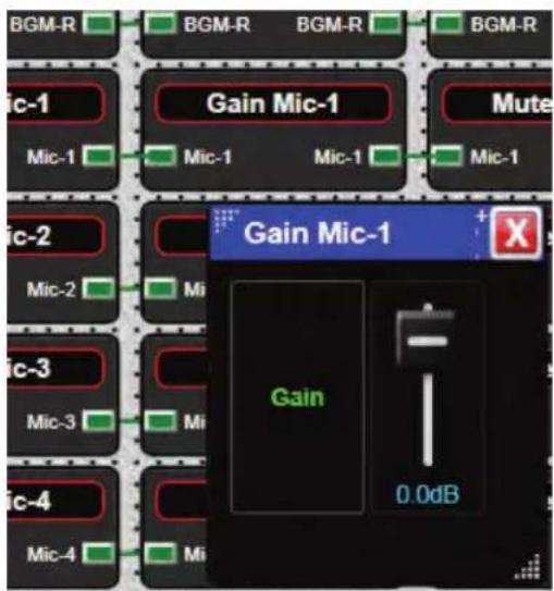
Figure 23

Atlas Sound
1601 Jack McKay Blvd. • Ennis, Texas 75119 U.S.A.
Telephone: 800.876.3333 • Fax: 800.765.3435
The Gain fader can be selected by holding the Ctrl key down while left clicking on the fader (Fig 23.1). The control can also be selected by holding the left mouse button and dragging a selection Box around the fader (Fig 27). When properly selected, the fader will be greyed out and a box will appear around it.
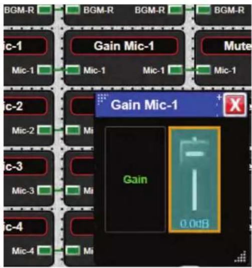
Figure 23.1
When the fader is highlighted, left click and hold, then drag to the control page. (Fig 24)
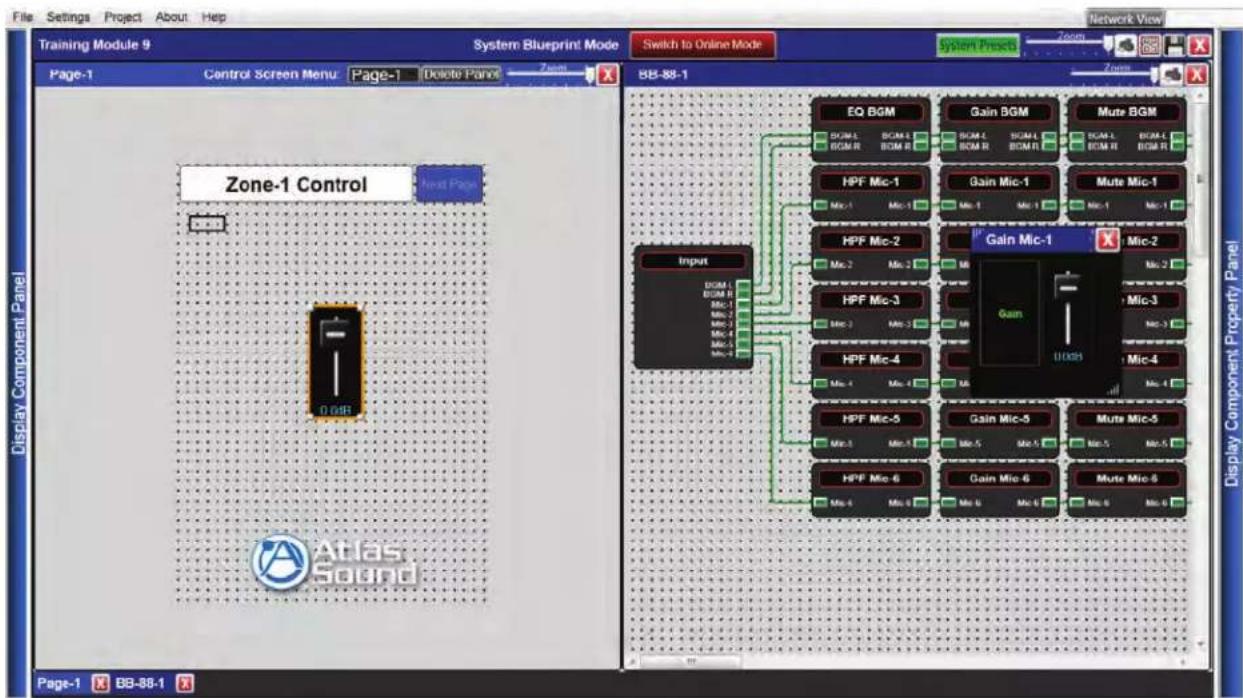
Figure 24
Once the control element is on the Control page it can be adjusted including size. Sometimes it is difficult to control a slide fader on a mobile device and because there may be several different scenarios, it is possible to turn this fader into several different types of gain controls. Complete this by right clicking on the fader and selecting Change Control Type. (Fig 25) The choices for the selected control element will be made available. (Fig 25.1)
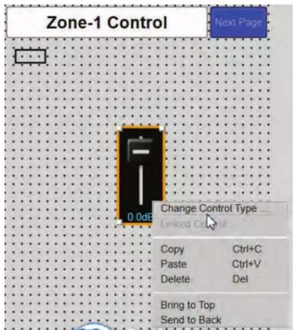
Figure 25
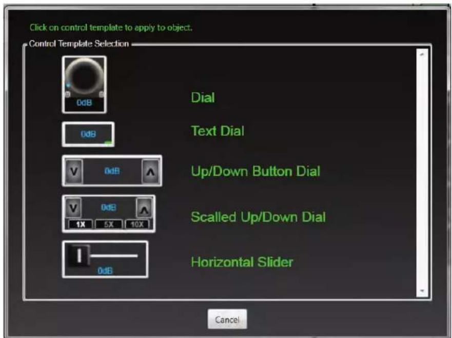
Figure 25.1

Atlas Sound
1601 Jack McKay Blvd. • Ennis, Texas 75119 U.S.A.
Telephone: 800.876.3333 • Fax: 800.765.3435
In the example an Up/Down Button Dial is needed for an iPhone ^® web browser design. The Fader has changed into the Up/Down but needs to be resized. (Fig 25.2)
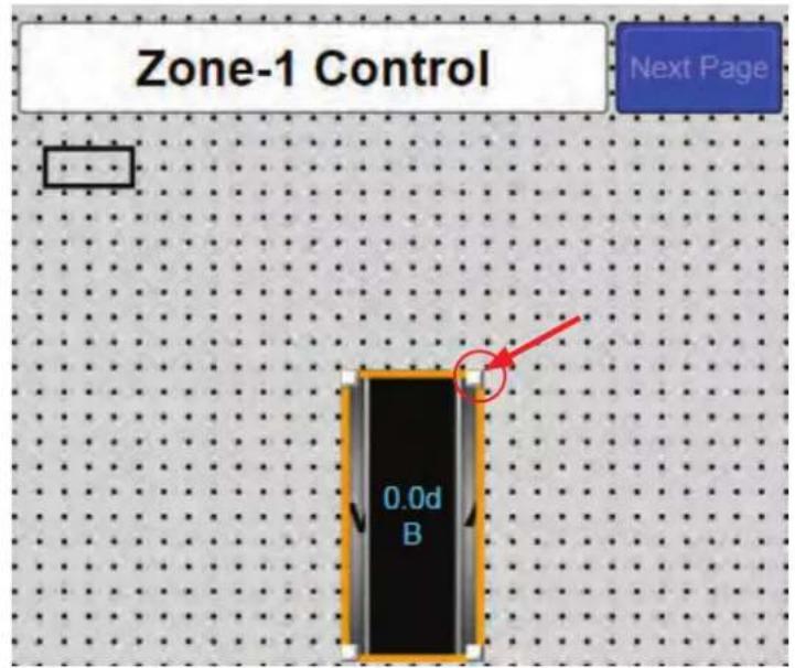
Figure 25.2
Highlight the control element by left clicking and dragging the corner to the desired size (Fig 25.3). The size can also be entered manually in the Components Properties pane.
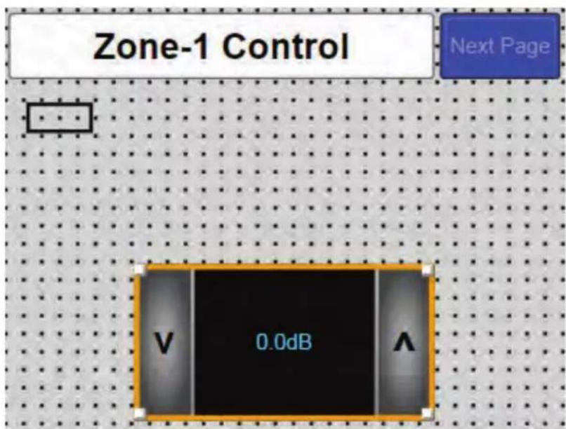
Figure 25.3
Once the control element is on the control page, component rages can be set using the component properties pane. Select the control element and use the component range box. The ranges for a gain control include minimum and maximum values and step size. (Fig 26)
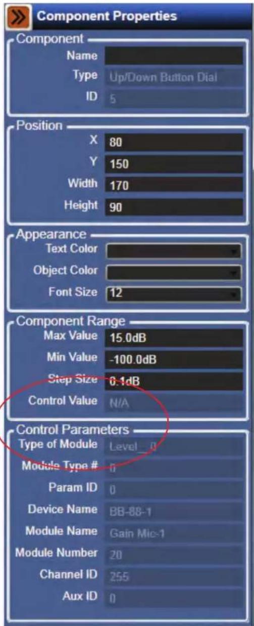
Figure 25.1
If a number of control elements have been added to a control page it is easy to lose track of what each item is controlling. Select the control element by left clicking on it by left clicking on it and look at the Control Parameters in the Component Properties pane will show what the module is and what DSP it is located in. This is very helpful when a design utilizes several BlueBridge® DSP processors.
A button type control element can be added to a control page similarly to the gain control above. In this example a Mute control is needed.
Select the Mute control by holding the left mouse button and dragging around the fader. (Fig 27)
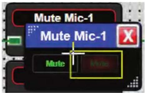
Figure 27
Once it is highlighted it can be dragged onto the control page.
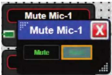
Figure 27.1
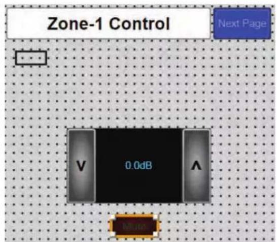
Figure 28
Once the control is on the control page grid and selected, the properties for that control element will be available in the Component Properties pane. In the case of this mute the On/Off state can be inverted, the text on the Mute can be changed, and the font can be adjusted. (Fig 29)
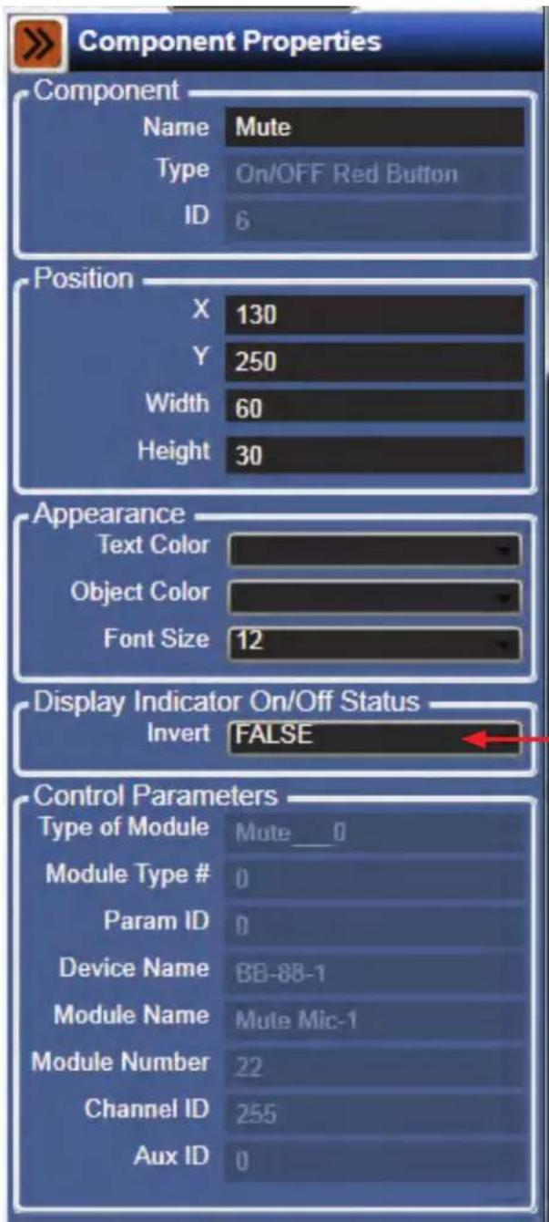
Figure 29
The corner of the control can be clicked to resize the control and/or right click on the control and select Change Control Type. (Fig 30)
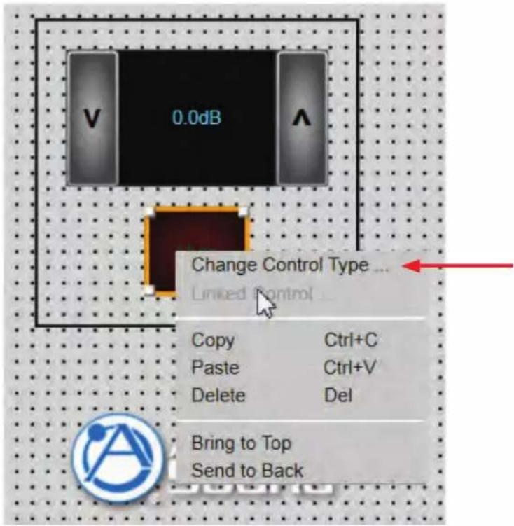
Figure 30
The choices for the selected control element will be made available. (Fig 30.1)
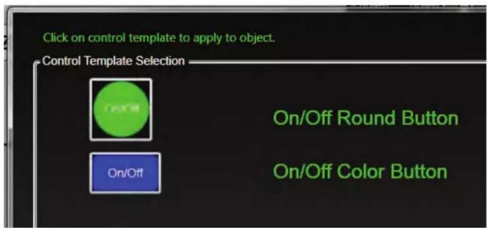
Figure 30.1
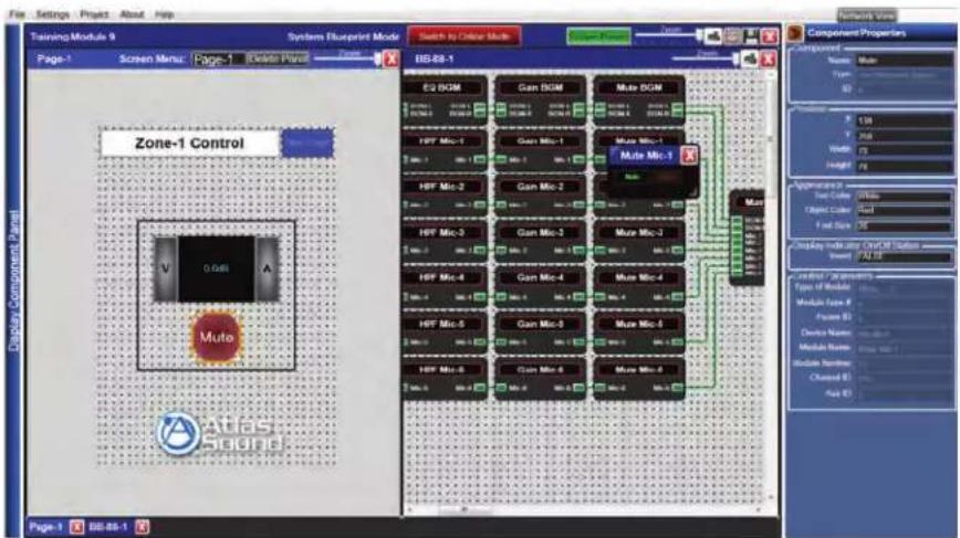
Figure 31
The rectangle (separator box) in Figures 31 and 31.1 has been adjusted to fit around the mic gain control and the mute button.
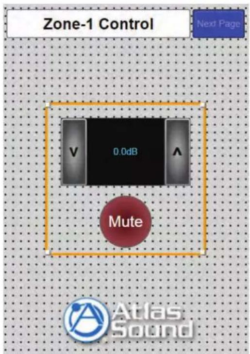
Figure 31.1
Click on the rectangle to highlight it and drag a corner to resize the rectangle. (Fig 31.1) When the rectangle is highlighted the keyboard arrow keys can also be used to move the rectangle to a desired location.
The appearance of the rectangle can be adjusted in the Component Properties pane.
The rectangle color and line thickness are adjusted in the corresponding boxes. (Fig 31.2 and 31.3)
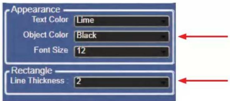
Figure 31.2
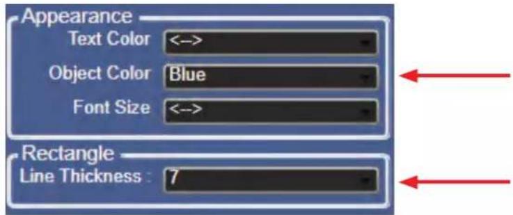
Figure 31.3
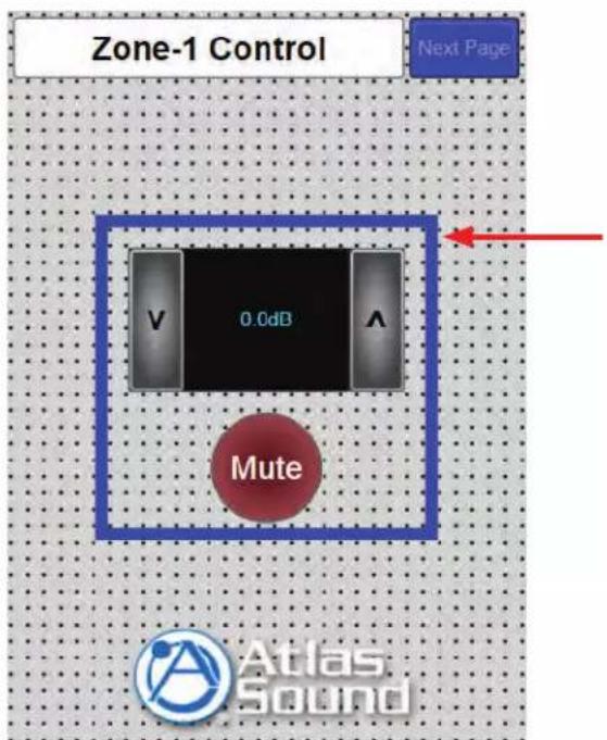
Figure 31.4
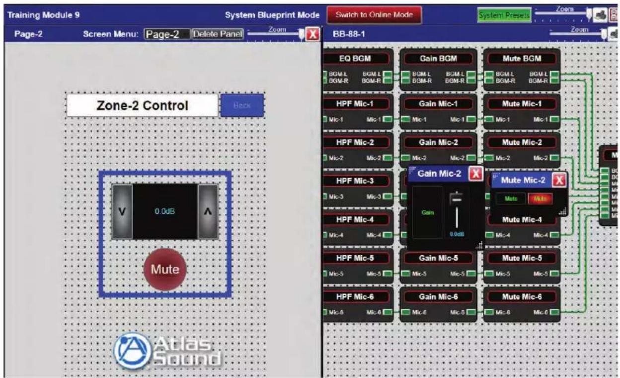
Figure 32
These easy steps can be used to create multiple custom control pages for the Web-Browser feature.
Enabling the BB-SM1 in Online Mode
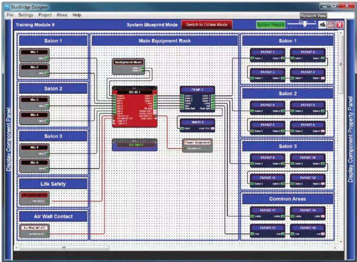
Once the custom control pages have been created and the design file has been saved, the design's hardware parameters need to be loaded into the design file using Online Mode.
The hardware in the design must be associated or "Mapped" to the actual hardware on the network.
flowchart
graph TD
    A["Air Wall Contact"] --> B["Life Safety"]
    B --> C["Main Equipment Rack"]
    C --> D["Background Music"]
    D --> E["BB-88.1"]
    E --> F["Power Sequencer"]
    F --> G["SM43T-1"]
    G --> H["F6.MF-1"]
    H --> I["Output"]
    I --> J["Display Component Panel"]

    K["Common Areas"] --> L["FAP42T-13"]
    K --> M["FAP42T-14"]
    K --> N["FAP42T-15"]
    K --> O["FAP42T-16"]

    P["Salon 1"] --> Q["Salon 1"]
    P --> R["Salon 2"]
    P --> S["Salon 3"]
    P --> T["Salon 3"]

    U["Salon 2"] --> V["FAP42T-5"]
    U --> W["FAP42T-6"]
    U --> X["FAP42T-7"]
    U --> Y["FAP42T-8"]

    Z["Salon 3"] --> AA["FAP42T-9"]
    Z --> AB["FAP42T-10"]
    Z --> AC["FAP42T-11"]
    Z --> AD["FAP42T-12"]

    AE["Main Equipment Rack"] --> AF["Background Music"]
    AF --> AG["BB-88.1"]
    AG --> AH["Power Sequencer"]
    AH --> AI["SM43T-1"]
    AI --> AJ["F6.MF-1"]
    AJ --> AK["F6.MF-2"]
    AJ --> AL["FAP42T-3"]
    AJ --> AM["FAP42T-4"]
    AJ --> AN["FAP42T-5"]
    AJ --> AO["FAP42T-6"]
    AJ --> AP["FAP42T-7"]
    AJ --> AQ["FAP42T-8"]

    AR["Display Component Panel"] --> AS["Air Wall NC-CC"]
    AR --> AT["BF-Safety NC-CC"]
Figure 33
Map the hardware by right clicking the BB-SM1 on the design file grid.
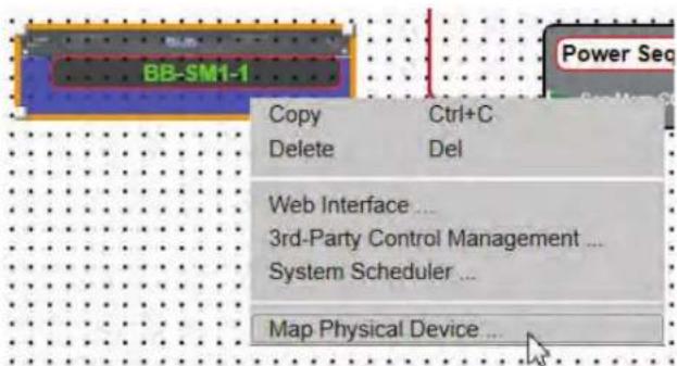
Figure 34
Select "Map Physical Device" (Fig 34) and a list will populate with all of the SM-1 devices available on the network. (Fig 34.1) The hardware name and MAC address will be listed for each device. Select the BB-SM1 unit that is used in the design. In this example only one BB-SM1 is in the list.
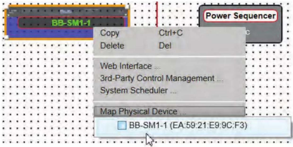
Figure 34.1
Once the Hardware is "Mapped", the module will turn a solid color (Fig 43.2). Note the un-mapped transparent color in Fig 34.1.
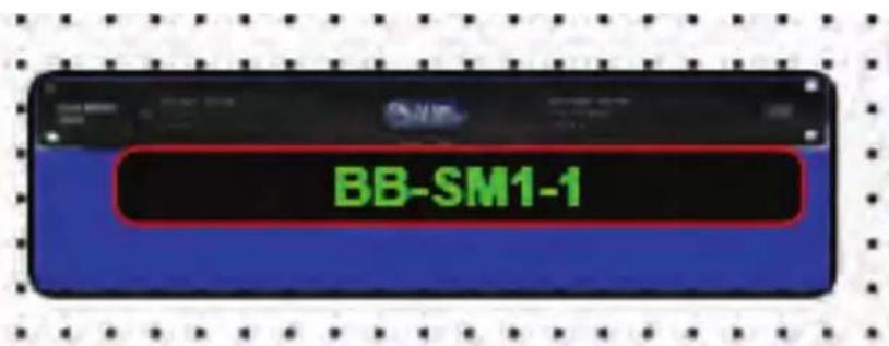
Figure 34.2
When all of the hardware in the design has been "Mapped", the control is ready to go Online.
Using Online Mode will load all the hardware in the design with all of their specific files and the systems will be functioning in a live state.
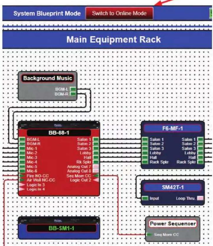
Once Hardware is mapped, click the "Switch to Online Mode" button at the center top of the design grid (Fig 35). The system will prompt to save the design file. (Fig 35.1)
flowchart
graph TD
    A["System Blueprint Mode"] --> B["Switch to Online Mode"]
    B --> C["Main Equipment Rack"]
    C --> D["Background Music"]
    D --> E["BB-88-1"]
    E --> F["F6-MF-1"]
    F --> G["SM42T-1"]
    G --> H["Power Sequencer"]
    H --> I["BB-SM1-1"]
    I --> J["Fire NO-CC"]
    I --> K["Air Wall NC-CC"]
    I --> L["Logic In 3"]
    I --> M["Logic In 4"]
    E --> N["BGM-L"]
    E --> O["BGM-R"]
    E --> P["BGM-L"]
    E --> Q["BGM-R"]
    E --> R["BGM-R"]
    E --> S["BGM-R"]
    E --> T["BGM-R"]
    E --> U["BGM-R"]
    E --> V["BGM-R"]
    E --> W["BGM-R"]
    E --> X["BGM-R"]
    E --> Y["BGM-R"]
    E --> Z["BGM-R"]
    E --> AA["BGM-R"]
    E --> AB["BGM-R"]
    E --> AC["BGM-R"]
    E --> AD["BGM-R"]
    E --> AE["BGM-R"]
    E --> AF["BGM-R"]
    E --> AG["BGM-R"]
    E --> AH["BGM-R"]
    E --> AI["BGM-R"]
    E --> AJ["BGM-R"]
    E --> AK["BGM-R"]
    E --> AL["BGM-R"]
    E --> AM["BGM-R"]
    E --> AN["BGM-R"]
    E --> AO["BGM-R"]
    E --> AP["BGM-R"]
    E --> AQ["BGM-R"]
    E --> AR["BGM-R"]
    E --> AS["BGM-R"]
    E --> AT["BGM-R"]
    E --> AU["BGM-R"]
    E --> AV["BGM-R"]
    E --> AW["BGM-R"]
    E --> AX["BGM-R"]
    E --> AY["BGM-R"]
    E --> AZ["BGM-R"]
    E --> BA["BGM-R"]
    E --> BB["BGM-R"]
    E --> BC["BGM-R"]
    E --> BD["BGM-R"]
    E --> BE["BGM-R"]
    E --> BF["BGM-R"]
    E --> BG["BGM-R"]
    E --> BH["BGM-R"]
    E --> BI["BGM-R"]
    E --> BJ["BGM-R"]
    E --> BK["BGM-R"]
    E --> BL["BGM-R"]
    E --> BM["BGM-R"]
    E --> BN["BGM-R"]
    E --> BO["BGM-R"]
    E --> BP["BGM-R"]
    E --> BQ["BGM-R"]
    E --> BR["BGM-R"]
    E --> BS["BGM-R"]
    E --> BT["BGM-R"]
    E --> BU["BGM-R"]
    E --> BV["BGM-R"]
    E --> BW["BGM-R"]
    E --> BX["BGM-R"]
    E --> BY["BGM-R"]
    E --> BZ["BGM-R"]
    E --> CA["BGM-R"]
    E --> CB["BGM-R"]
    E --> CC["BGM-R"]
    E --> CD["BGM-R"]
    E --> CE["BGM-R"]
Figure 35
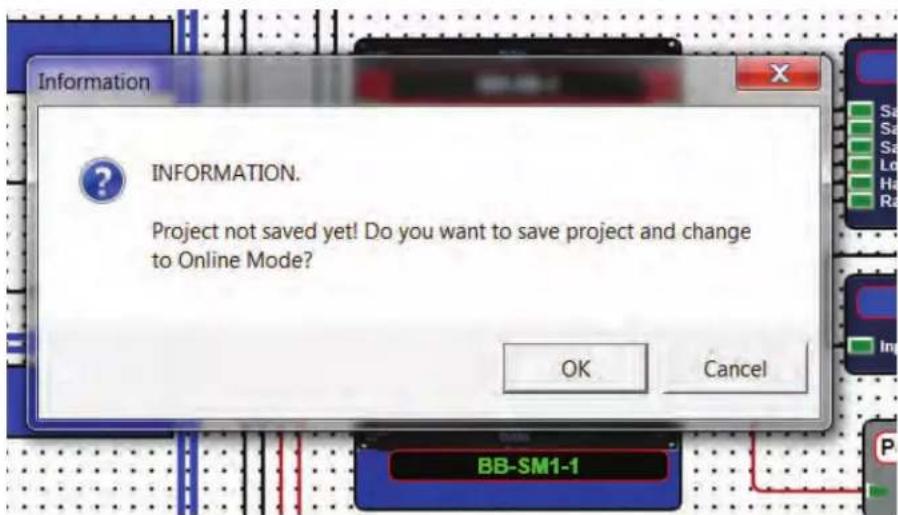
Figure 35.1
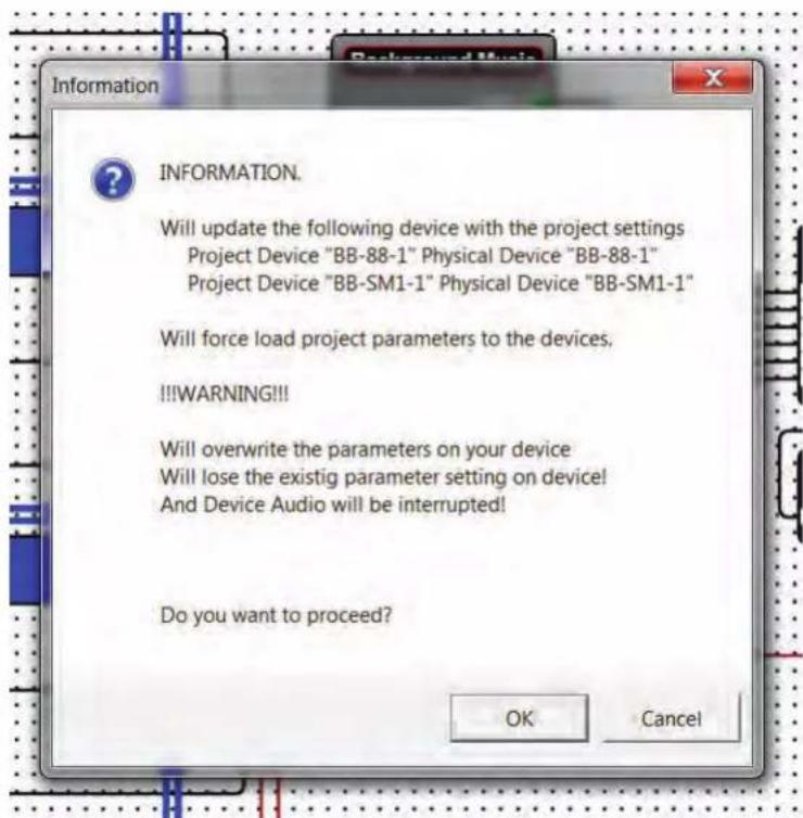
Figure 35.2
The loading process will begin and may take a few minutes. The gauges at the top of the hardware icons illustrate writing progress. (Fig 35.3)
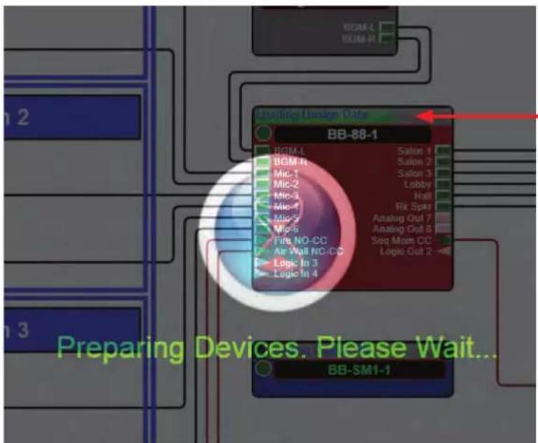
Figure 35.3

Atlas Sound
1601 Jack McKay Blvd. • Ennis, Texas 75119 U.S.A.
Telephone: 800.876.3333 • Fax: 800.765.3435
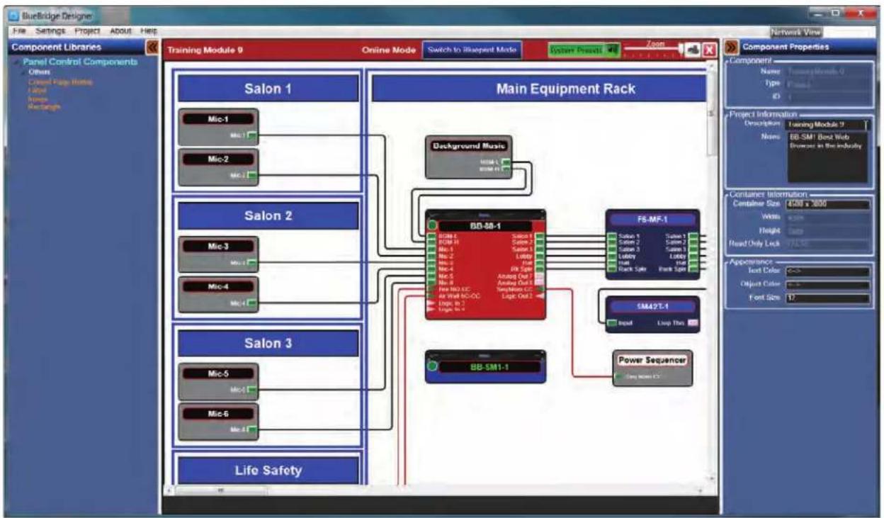
When this process is complete the design grid will turn to a solid white background. (Fig 35.4)
flowchart
graph TD
    subgraph_Salon_1["Salon 1"]
        A1["Mic-1"] --> B1["Background Music"]
        A2["Mic-2"] --> B1
        A3["Mic-3"] --> B1
        A4["Mic-4"] --> B1
        A5["Mic-5"] --> B2["BD-SB-1"]
        A6["Mic-6"] --> B2
    end

    subgraph_Main_Equipment_Rack["Main Equipment Rack"]
        B1 --> C1["BB-SB-1"]
        B1 --> C2["FS-MF-1"]
        C1 --> D1["Salon 1"]
        C1 --> D2["Salon 2"]
        C1 --> D3["Salon 3"]
        C1 --> D4["Lobby"]
        C1 --> D5["Back Split"]
        C2 --> D5
        C2 --> D6["Power Sequencer"]
        C2 --> D7["SM42T-1"]
        C2 --> D8["Input Loop This"]
    end

    subgraph_Life_Safety["Life Safety"]
        B2 --> D9["BB-SM1-1"]
    end

    style Salon_1 fill:#f9f,stroke:#333
    style Main Equipment Rack fill:#ccf,stroke:#333
    style Life_Safety fill:#cfc,stroke:#333
Figure 35.4
The system is now live and ready to be controlled with the web browser function.
The IP address of the BB-SM1 is required to use the web browser for control. This is found in the Network View, which is accessible by selecting the Network View Button at the top right section over the Component Properties pane. (Fig 36)
Note: It is not necessary for the Component Properties pane to be open for this function
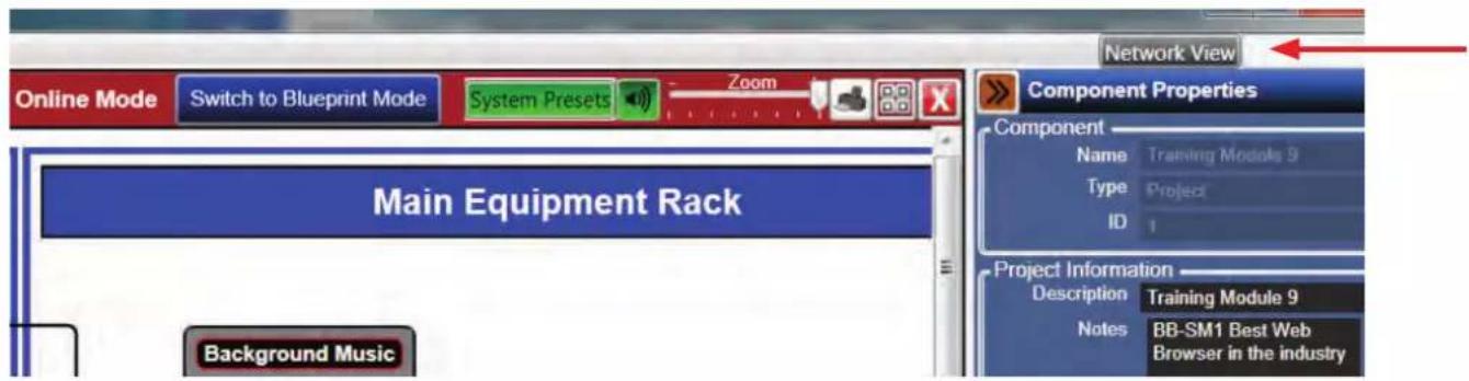
Figure 36
The Network View page will open and there will be a visual of all the BlueBridge hardware that is currently on the network. (Fig 36.1) Locate the BB-SM1 hardware block and locate its IP address.
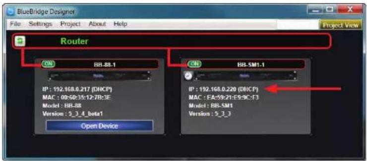
Figure 36.1
Open a web browser on any web enabled device.
Ensure the web enabled device is on the same network as the BlueBridge® DSP systems.
Note: Atlas Sound recommends using Google® Chrome® or Apple® Safari® for controlling BlueBridge® systems. The Web Browser control pages will use the Default Font chosen for the browser. This can be changed in the browser settings.
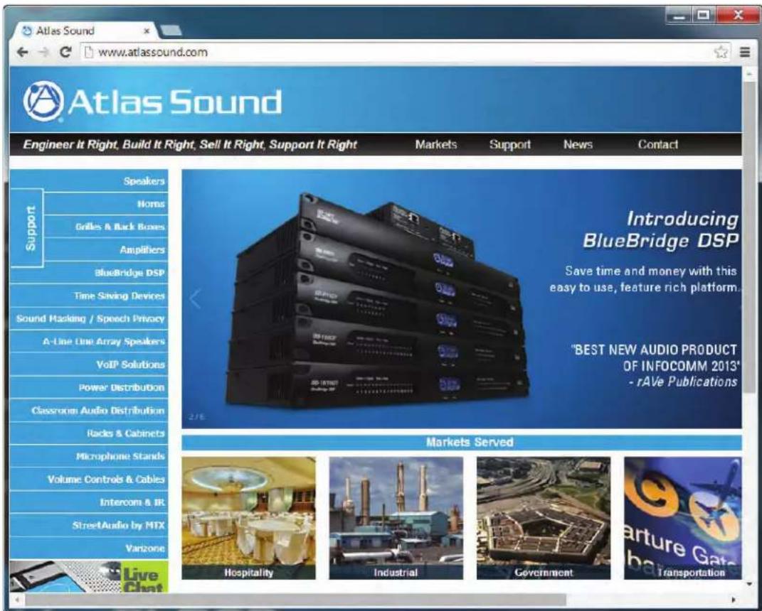
Figure 37

Atlas Sound
1601 Jack McKay Blvd. • Ennis, Texas 75119 U.S.A.
Telephone: 800.876.3333 • Fax: 800.765.3435
Enter the IP address of the BB-SM1 into the web browser address bar, in this example, 192.168.0.220 (Fig 39), and then hit the enter key on the keyboard.
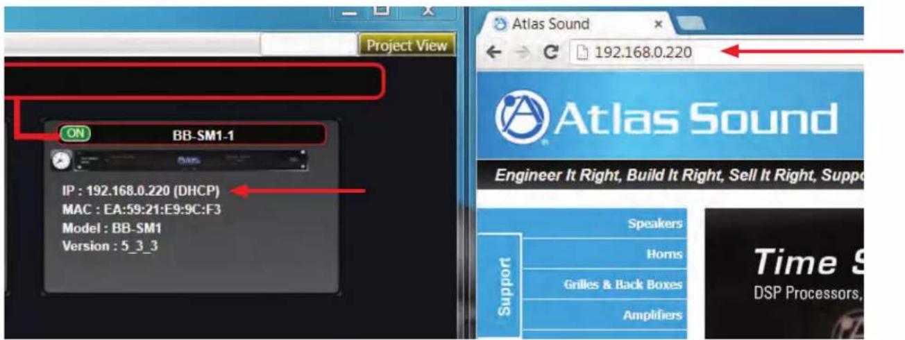
Figure 39
An Atlas Control web page will populate with a reference to the control pages that were created. (Fig 39.1)

Figure 39.1
Select a Page and the control pages that were created will be available to use. (Fig 39.2)
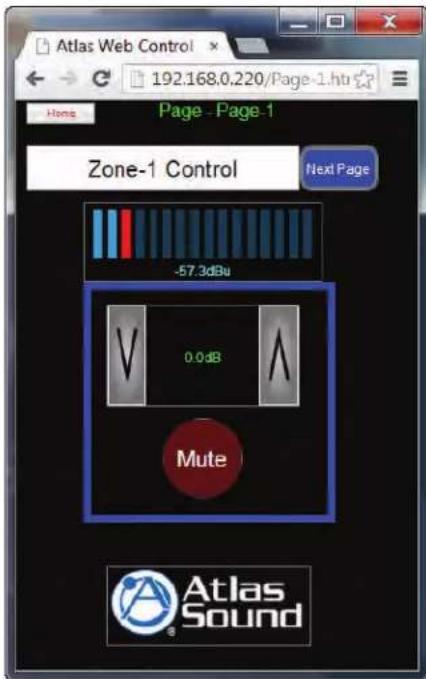
Figure 39.2
Maximize the design. The use of a large numbers of level meters can create a lot of network traffic that may cause slow control response. Consideration for this should be made during the Control design stage.
3rd Party Control Management
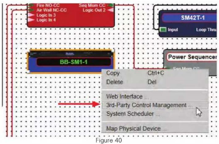
Adding 3rd party control begins with the design file open and in System BluePrint mode (not online). Right click the BB-SM1 and select 3rd Party Control Management (Fig 40). A design grid for the 3rd Party Control will open. (Fig 41)

Atlas Sound
1601 Jack McKay Blvd. • Ennis, Texas 75119 U.S.A.
Telephone: 800.876.3333 • Fax: 800.765.3435
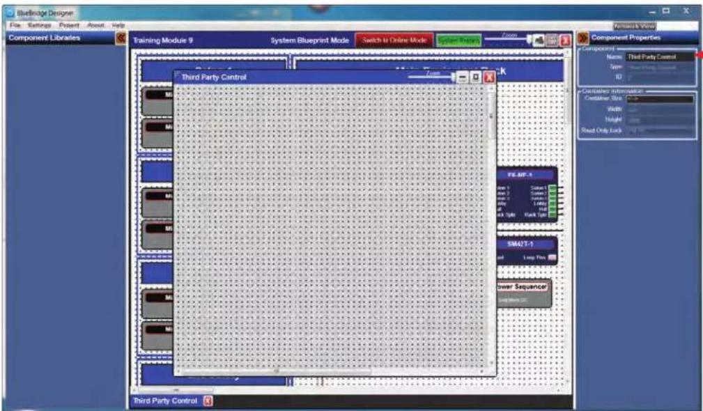
Figure 41
If desired, the Page can be named for easy identification in the Component Properties panel. (Fig 41)
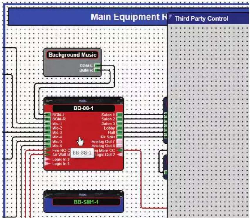
On the BluePrint page, double click the DSP block that contains the module/s that will be controlled by the 3rd party equipment. (Fig 42)
flowchart
graph TD
    A["Main Equipment R"] --> B["Background Music"]
    A --> C["BB-88-1"]
    A --> D["BB-SM1-1"]
    B --> E["BGM-L"]
    B --> F["BGM-R"]
    C --> G["BGM-L"]
    C --> H["BGM-R"]
    C --> I["BGM-L"]
    C --> J["BGM-R"]
    C --> K["BGM-L"]
    C --> L["BGM-R"]
    C --> M["BGM-L"]
    C --> N["BGM-R"]
    C --> O["BGM-L"]
    C --> P["BGM-R"]
    C --> Q["BGM-L"]
    C --> R["BGM-R"]
    C --> S["BGM-L"]
    C --> T["BGM-R"]
    C --> U["BGM-L"]
    C --> V["BGM-R"]
    C --> W["BGM-L"]
    C --> X["BGM-R"]
    C --> Y["BGM-L"]
    C --> Z["BGM-R"]
    C --> AA["BGM-L"]
    C --> AB["BGM-R"]
    C --> AC["BGM-L"]
    C --> AD["BGM-R"]
    C --> AE["BGM-L"]
    C --> AF["BGM-R"]
    C --> AG["BGM-L"]
    C --> AH["BGM-R"]
    C --> AI["BGM-L"]
    C --> AJ["BGM-R"]
    C --> AK["BGM-L"]
    C --> AL["BGM-R"]
    C --> AM["BGM-L"]
    C --> AN["BGM-R"]
    C --> AO["BGM-L"]
    C --> AP["BGM-R"]
    C --> AQ["BGM-L"]
    C --> AR["BGM-R"]
    C --> AS["BGM-L"]
    C --> AT["BGM-R"]
    C --> AU["BGM-L"]
    C --> AV["BGM-R"]
    C --> AW["BGM-L"]
    C --> AX["BGM-R"]
    C --> AY["BGM-L"]
    C --> AZ["BGM-R"]
    C --> BA["BGM-L"]
    C --> BB["BGM-R"]
    C --> BC["BGM-L"]
    C --> BD["BGM-R"]
    C --> BE["BGM-L"]
    C --> BF["BGM-R"]
    C --> BG["BGM-L"]
    C --> BH["BGM-R"]
    C --> BI["BGM-L"]
    C --> BJ["BGM-R"]
    C --> BK["BGM-L"]
    C --> BL["BGM-R"]
    C --> BM["BGM-L"]
    C --> BN["BGM-R"]
    C --> BO["BGM-L"]
    C --> BP["BGM-R"]
    C --> BQ["BGM-L"]
    C --> BR["BGM-R"]
    C --> BS["BGM-L"]
    C --> BT["BGM-R"]
    C --> BU["BGM-L"]
    C --> BV["BGM-R"]
    C --> BW["BGM-L"]
    C --> BX["BGM-R"]
    C --> BY["BGM-L"]
    C --> BZ["BGM-R"]
    C --> CA["BGM-L"]
    C --> CB["BGM-R"]
    C --> CC["BGM-L"]
    C --> CD["BGM-R"]
    C --> CE["BGM-L"]
    C --> CF["BGM-R"]
    C --> CG["BGM-L"]
    C --> CH["BGM-R"]
    C --> CI["BGM-L"]
    C --> CJ["BGM-R"]
    C --> CK["BGM-L"]
    C --> CL["BGM-R"]
    C --> CM["BGM-L"]
    C --> CN["BGM-R"]
    C --> CO["BGM-L"]
    C --> CP["BGM-R"]
    C --> CQ["BGM-L"]
    C --> CR["BGM-R"]
    C --> CS["BGM-L"]
    C --> CT["BGM-R"]
    C --> CU["BGM-L"]
    C --> CV["BGM-R"]
    C --> CW["BGM-L"]
Figure 42
flowchart
graph TD
    subgraph Main Equipment R
        A["HPF- Salon 1"] --> B["PEQ- Salon 1"]
        C["HPF- Salon 2"] --> D["PEQ- Salon 2"]
        E["HPF- Salon 3"] --> F["PEQ- Salon 3"]
        G["HPF- Lobby"] --> H["PEQ- Lobby"]
        I["HPF- Hall"] --> J["PEQ- Hall"]
        K["HPF- Rack Spkr"] --> L["PEQ- Rack Spkr"]
        M["Logic Input"] --> N["Fan N3-CG & Wall N5-CG"]
    end

    subgraph System Blueprint Mode
        O["Main Equipment R"] --> P["Display Component Property Panel"]
    end

    style Main Equipment R fill:#f9f,stroke:#333
    style System Blueprint Mode fill:#ccf,stroke:#333
    style System Blueprint Mode fill:#cfc,stroke:#333
    style System Blueprint Mode fill:#fcc,stroke:#333
    style System Blueprint Mode fill:#ffc,stroke:#333
    style System Blueprint Mode fill:#fcc,stroke:#333
    style System Blueprint Mode fill:#ccf,stroke:#333
    style System Blueprint Mode fill:#cfc,stroke:#333
    style System Blueprint Mode fill:#fcc,stroke:#333
    style System Blueprint Mode fill:#ffc,stroke:#333
    style System Blueprint Mode fill:#fcc,stroke:#333
    style System Blueprint Mode fill:#ccf,cfc,stroke:#333
    style System Blueprint Mode fill:#cfc,stroke:#333
    style System Blueprint Mode fill:#fcc,stroke:#333
    style System Blueprint Mode fill:#ffc,stroke:#333
    style System Blueprint Mode fill:#fcc,stroke:#333
    style System Blueprint Mode fill:#ccf,stroke:#333
    style System Blueprint Mode fill:#fcc,stroke:#333
    style System Blueprint Mode fill:#ffc,stroke:#333
    style System Blueprint Mode fill:#fcc,stroke:#333
    style System Blueprint Mode fill:#ccf,stroke:#333
    style System Blueprint Mode fill:#fcc,stroke:#333
    style System Blueprint Mode fill:#ffc,stroke-dasharray: 5 5
Figure 42.1
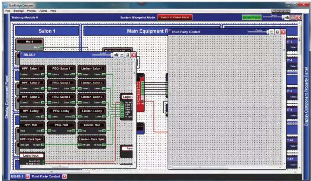
Open the DSP Module/s that will be controlled. In this example a Gain and a Mute will be controlled. (Fig 43)
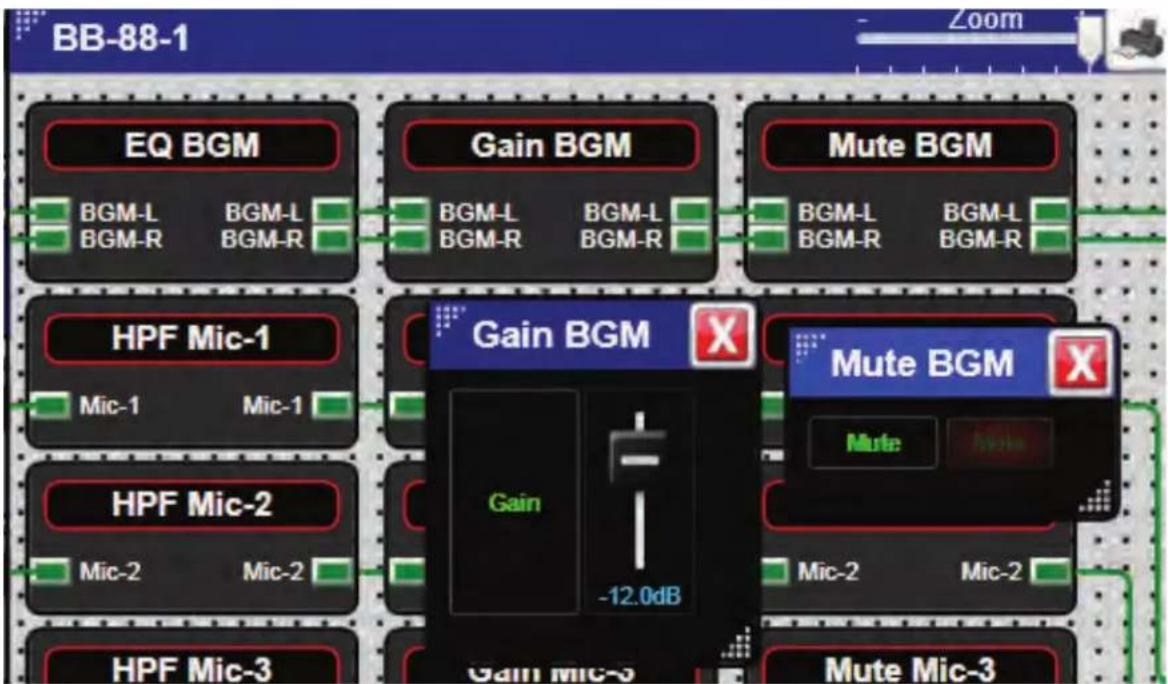
Figure 43

Atlas Sound
1601 Jack McKay Blvd. • Ennis, Texas 75119 U.S.A.
Telephone: 800.876.3333 • Fax: 800.765.3435
Highlight the control element and then press the Control and left mouse click on the Fader or Button that will be controlled. (Fig 44) Drag onto the Third Party Control Grid. (Fig 45)
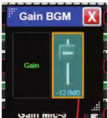
Figure 44
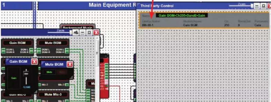
Figure 45
Repeat the same steps for the Mute. (Fig 45.1 and Fig 45.2)
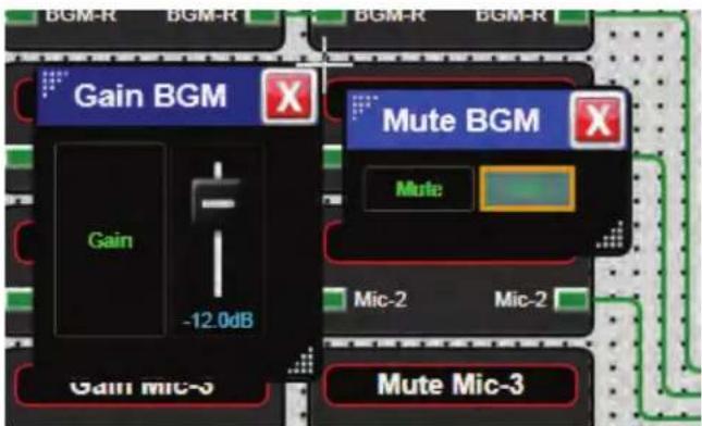
Figure 45.1
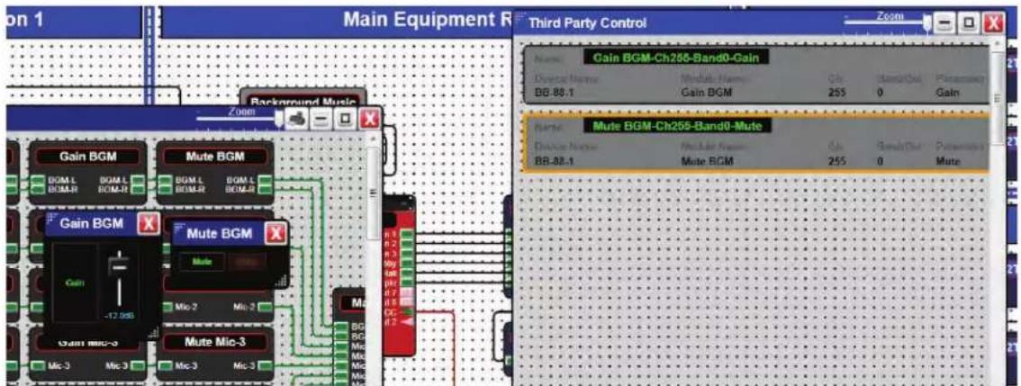
Figure 45.2
The Control Element Parameters will appear on the grid ready for control by the 3rd party control system.
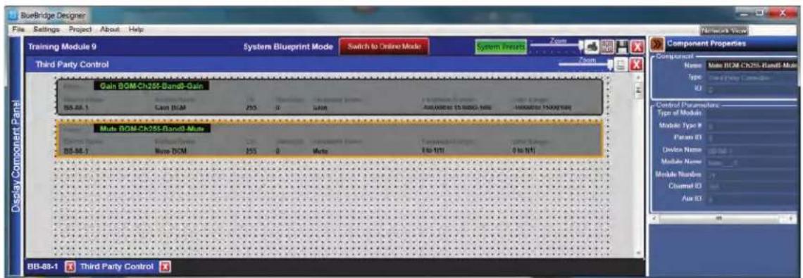
Figure 46
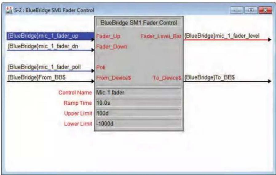
Left mouse click on any element parameter block to give that element a distinctive name in the Component Properties pane. (Fig 46.1) This Name is the identifier that the control system uses for communication with this control element. In this example it is "Mute-1"
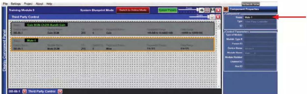
Figure 46.1

Atlas Sound
1601 Jack McKay Blvd. • Ennis, Texas 75119 U.S.A.
Telephone: 800.876.3333 • Fax: 800.765.3435
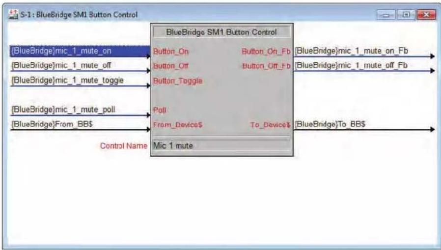
This will set up the control elements for use with a 3rd party control system and can be handed off to the programmer. Once all of the control elements have been dragged into this grid and assigned a unique name for identification, this control element can be controlled by RS232, TCP or UDP.
Control Protocol for BlueBridge Products is available on the Atlas website at:
www.atlassound.com/BlueBridge/Training/FileList
Crestron Modules are also available on the Atlas website.
See Examples (Fig 47 & Fig 47.1)
flowchart
graph TD
    A["BlueBridge"]mic_1_mute_on --> B["Button_On"]
    A --> C["Button_On_Fb"]
    D["BlueBridge"]mic_1_mute_off --> E["Button_Off"]
    F["BlueBridge"]mic_1_mute_toggle --> G["Button_Toggle"]
    H["BlueBridge"]mic_1_mute_poll --> I["Poll"]
    J["BlueBridge"]From_BB--> K["From_Device"]
    L["Control Name"] --> M["Mic 1 mute"]
    N["BlueBridge"]mic_1_mute_off_Fb --> O["BlueBridge"]mic_1_mute_off_Fb]
    P["BlueBridge"]mic_1_mute_off_Fb --> Q["BlueBridge"]mic_1_mute_off_Fb]
    R["BlueBridge"]mic_1_mute_off_Fb --> S["BlueBridge"]mic_1_mute_off_Fb]
    T["BlueBridge"]mic_1_mute_off_Fb --> U["BlueBridge"]mic_1_mute_off_Fb]
Figure 47
flowchart
graph TD
    A["BlueBridge"]mic_1_fader_up --> B["Fader_Up"]
    A --> C["Fader_Down"]
    D["BlueBridge"]mic_1_fader_dn --> E["Poll"]
    F["BlueBridge"]mic_1_fader_poll --> G["From_Device$"]
    H["BlueBridge"]From_BB--> I["To_Device"]
    J["Control Name"] --> K["Mic 1 fader"]
    L["Ramp Time"] --> M["10.0s"]
    N["Upper Limit"] --> O["100d"]
    P["Lower Limit"] --> Q["-1000d"]
    R["BlueBridge"]mic_1_fader_level --> S["BlueBridge"]mic_1_fader_level
    T["BlueBridge"]mic_1_fader_poll --> U["BlueBridge"]mic_1_fader_level
    V["BlueBridge"]mic_1_fader_up --> W["Fader_Up"]
    X["BlueBridge"]mic_1_fader_dn --> Y["Fader_Up"]
Figure 47.1
System Scheduler
To use the system scheduler the design file must have presets previously created for the design file. Please refer to the "Presets Guide" available on atlassound.com/BlueBridge for information regarding creating and working with Presets.
With the design file open and in "System BluePrint Mode", right click the BB-SM1 and select System Scheduler from the drop down menu (Fig 48). A design grid for the System Scheduler will open. (Fig 49)
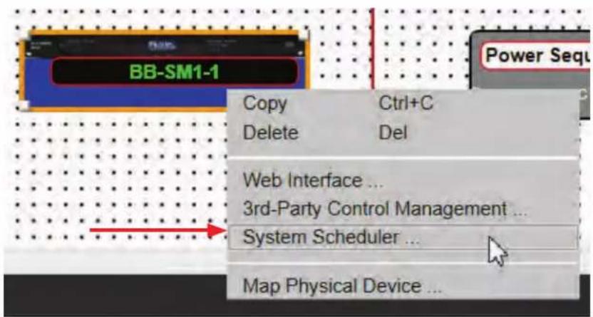
Figure 48
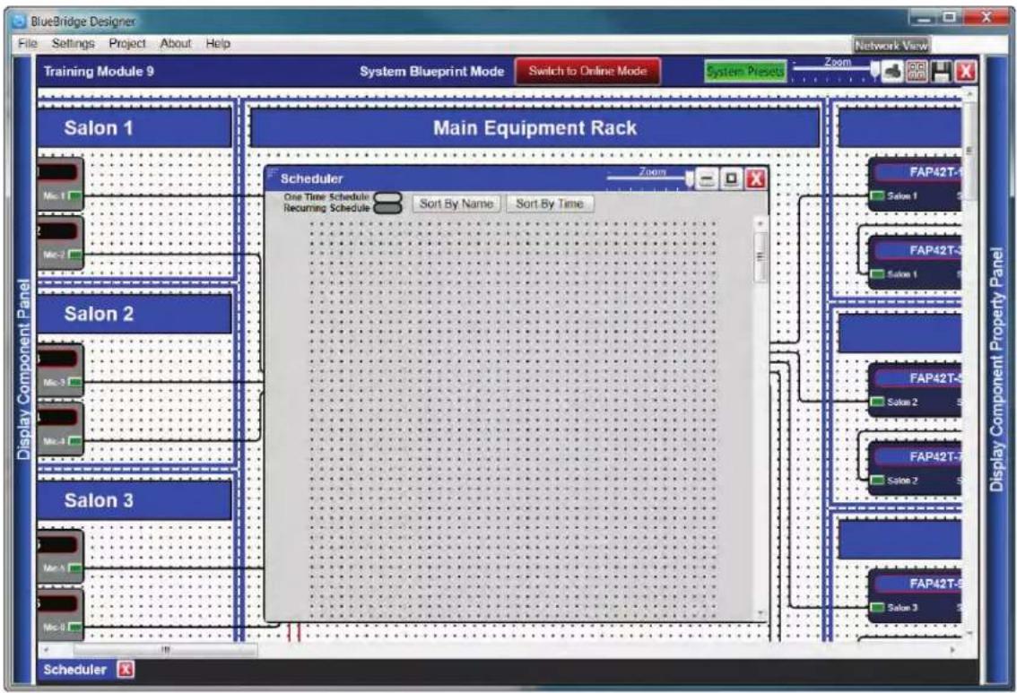
Figure 49

Atlas Sound
1601 Jack McKay Blvd. • Ennis, Texas 75119 U.S.A.
Telephone: 800.876.3333 • Fax: 800.765.3435
Make sure the Component Libraries pane is open and left click on the grid to bring up a list of presets in the Component Libraries pane. (Fig 50)
Make sure the Component Properties pane is also open as this will be where most of the work is done.
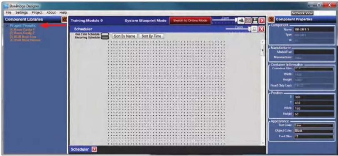
Figure 50
Choose the preset that will be used in a scheduled event from the list in the Component Libraries pane. (Fig 51)
Left click and hold the preset while dragging to the Schedule grid and release onto the grid. A schedule event will be created. (Fig 52)
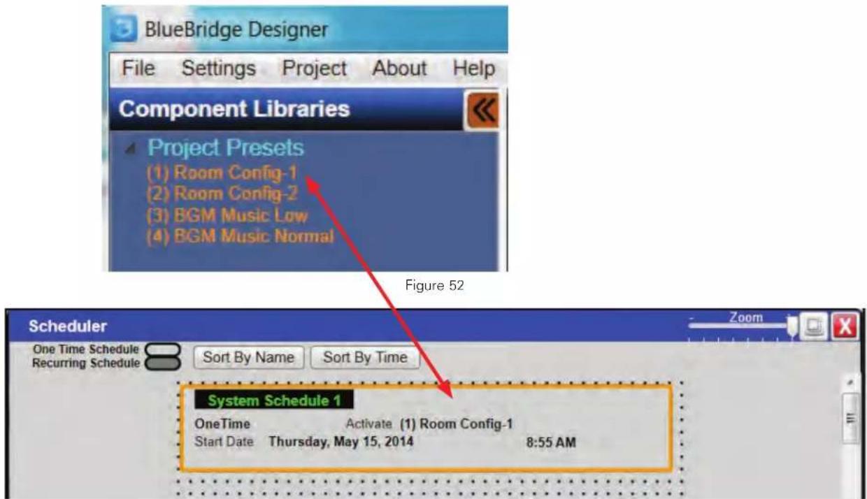
Figure 52
Now the schedule event can be adjusted for use.
The set up for each schedule event is done in the Component Properties pane. (Fig 53)
A name should be given to identify the schedule event.
In the properties section the active preset can also be changed.
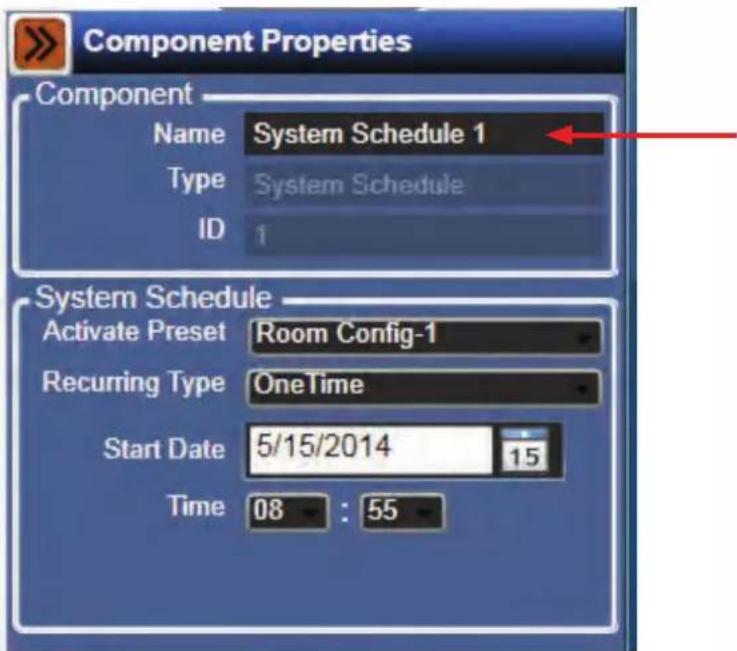
Figure 53
The recurring type can be set using the drop down box. (Fig 54)
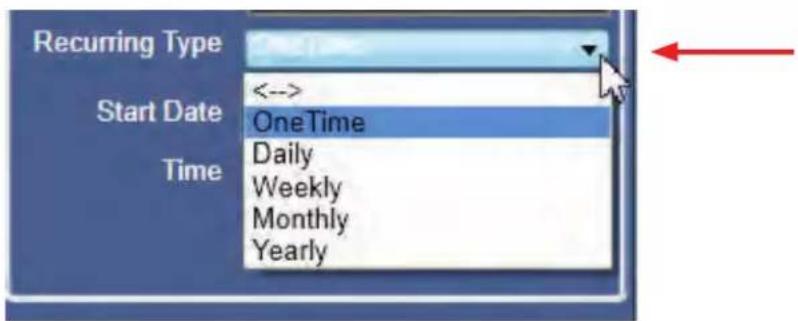
Figure 54
A start date can be set. (Fig 55)
Type the date in the Start Date field or use the calendar by clicking on the calendar icon.
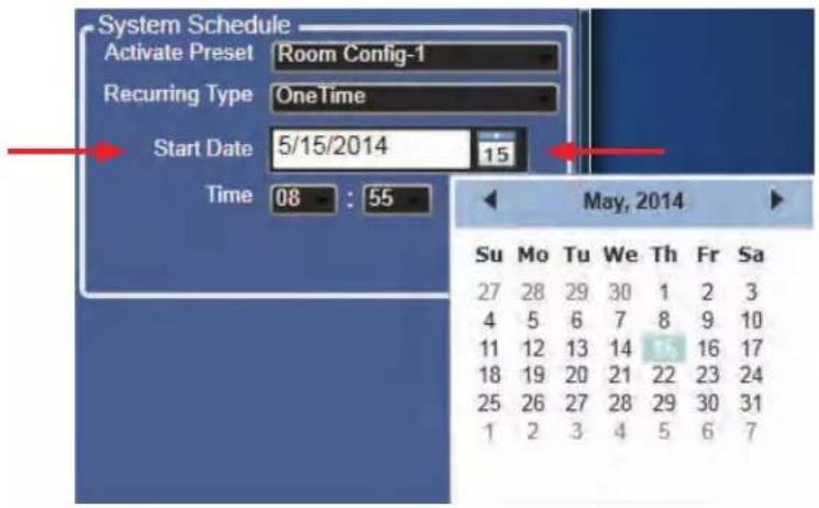
Figure 55
Set the event start time. (Fig 56)
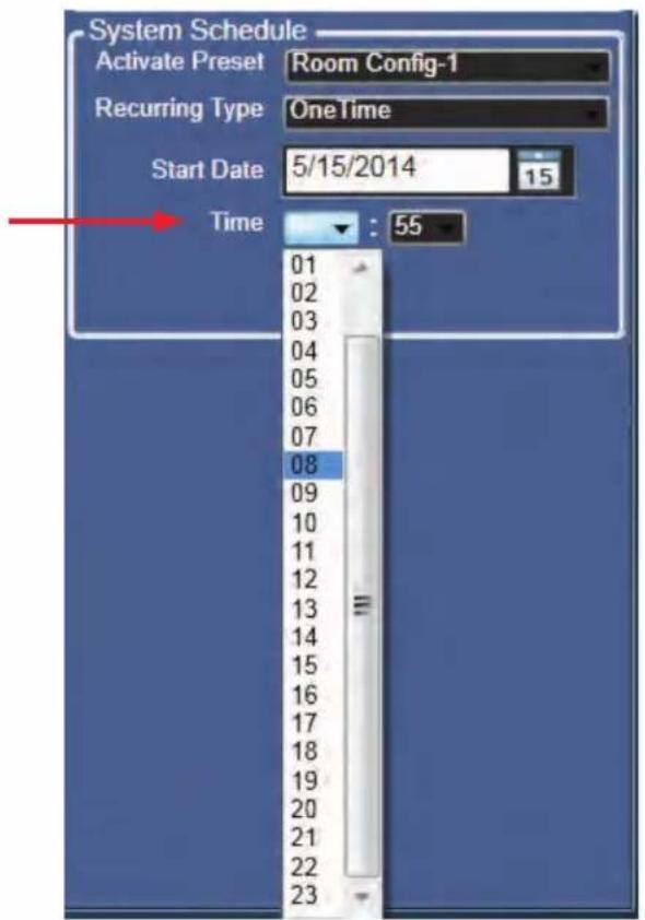
Figure 56
Once all of the schedule events have been created they can be sorted on the grid field.
The choices are to Sort By Name (Fig 57) or Time. (Fig 58)
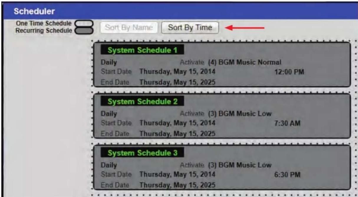
Figure 57
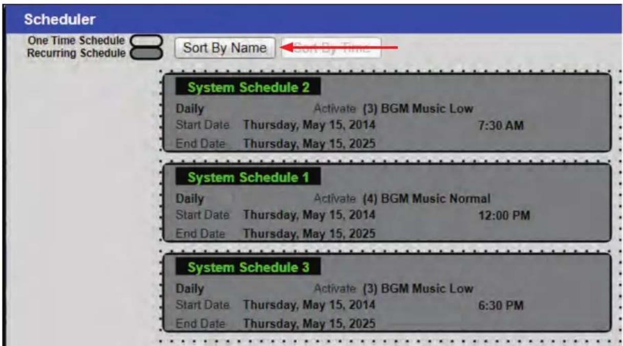
Figure 58

Atlas Sound
1601 Jack McKay Blvd. • Ennis, Texas 75119 U.S.A.
Telephone: 800.876.3333 • Fax: 800.765.3435
Master Project Backup
The Master Project backup will store the site files and parameters for all devices in a system design. These files will be stored in the BB-SM1. To create a Master Project Backup all hardware must be present on the network. While in BluePrint Mode, from the Project Menu select Backup project to Site Manager. (Fig 59)
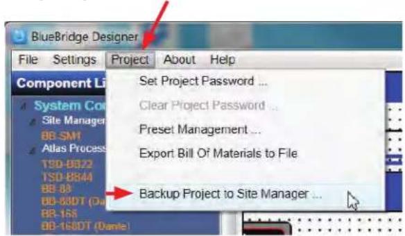
Figure 59
Select the SM-1 that will store the Backup file. (Fig 60)
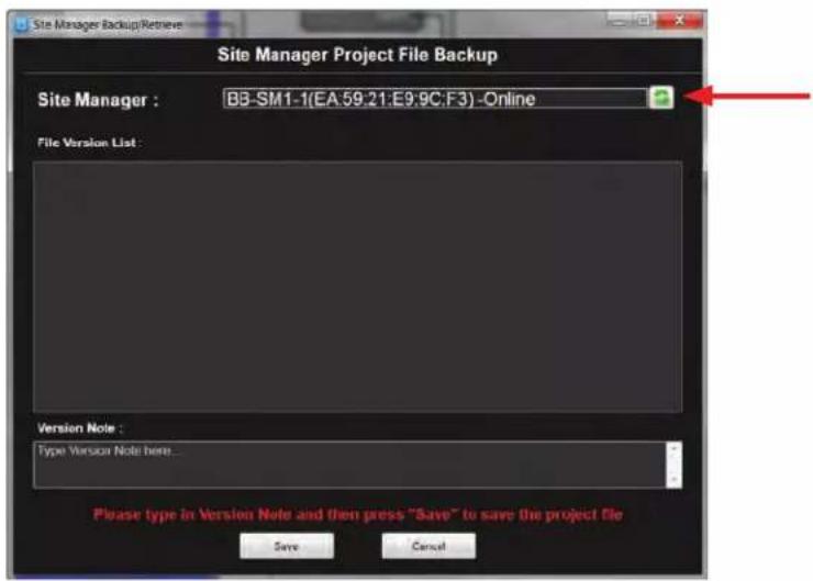
Figure 60
If it is a new backup, type a name in the version note box and save. (Fig 61)
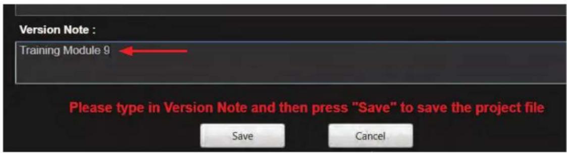
Figure 61
Follow the instructions in the popup window.
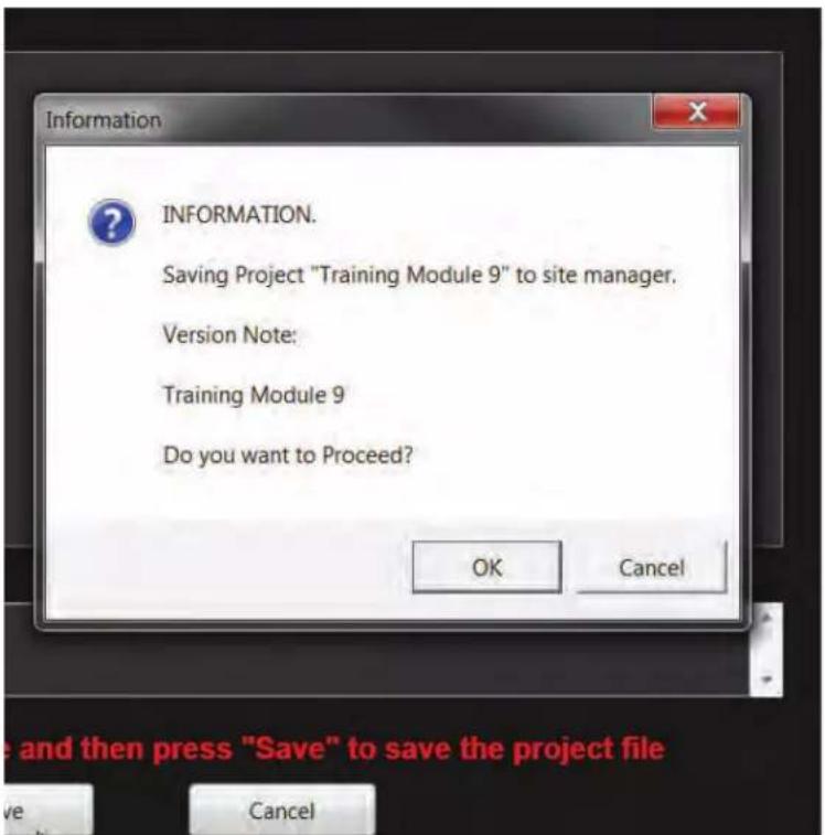
Figure 61.1
A list of versions will be created for later use including time and date of save. (Fig 62)
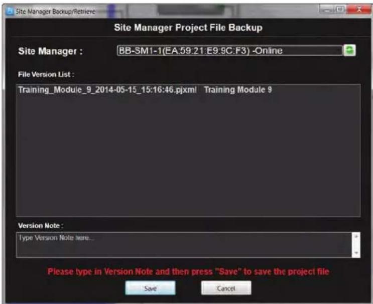
Figure 62

Atlas Sound
1601 Jack McKay Blvd. • Ennis, Texas 75119 U.S.A.
Telephone: 800.876.3333 • Fax: 800.765.3435
The project file can be retrieved from the File Menu once it has been saved.
To retrieve the design file BlueBridge Designer must be restarted. It is best to select the Start "Network View" button when the software reboots. (Fig 63)
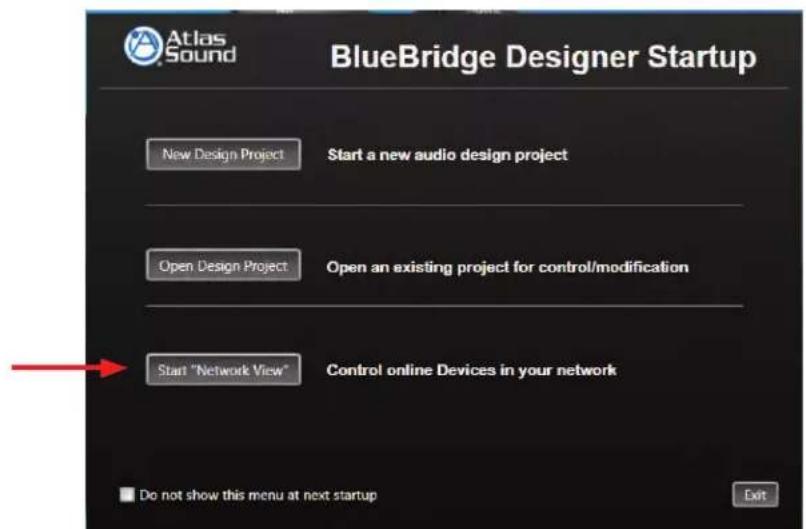
Figure 63
Click the Project View Button while in the Network View. This will bring up a blank designer window. (Fig 64)
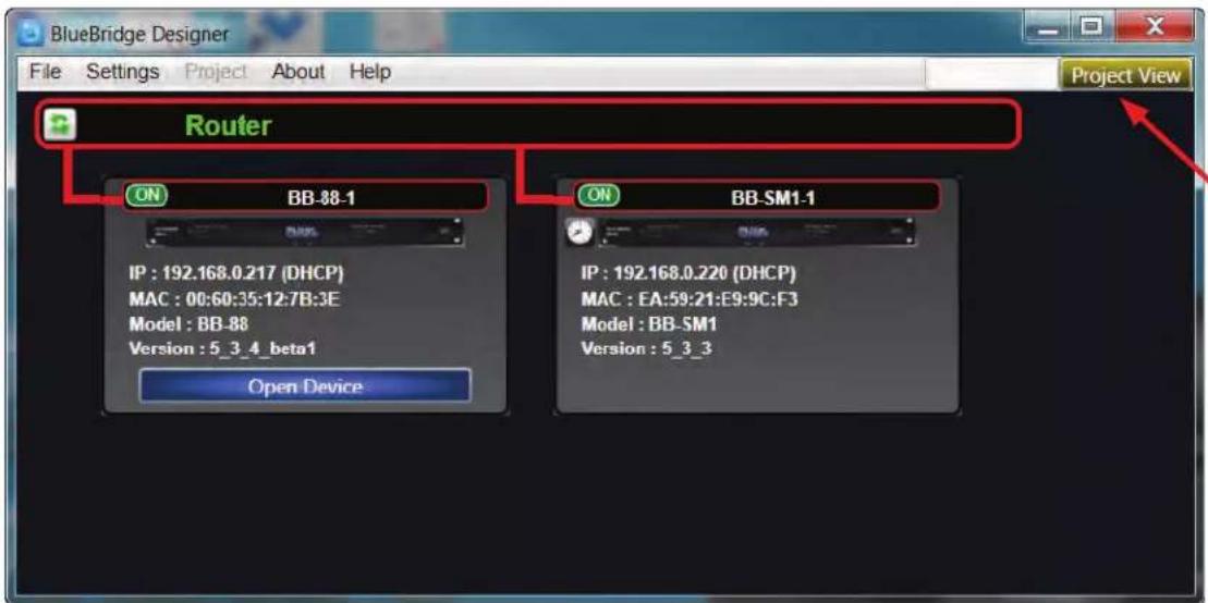
Figure 64
With the blank designer window open, select "Retrieve Project form Site Manager" from the file menu. (Fig 65)
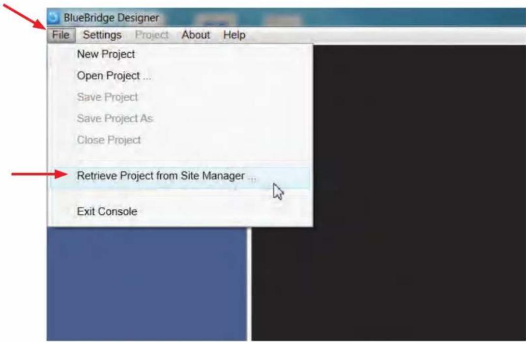
Figure 65
A Backup Retrieve window will appear. (Fig 66)
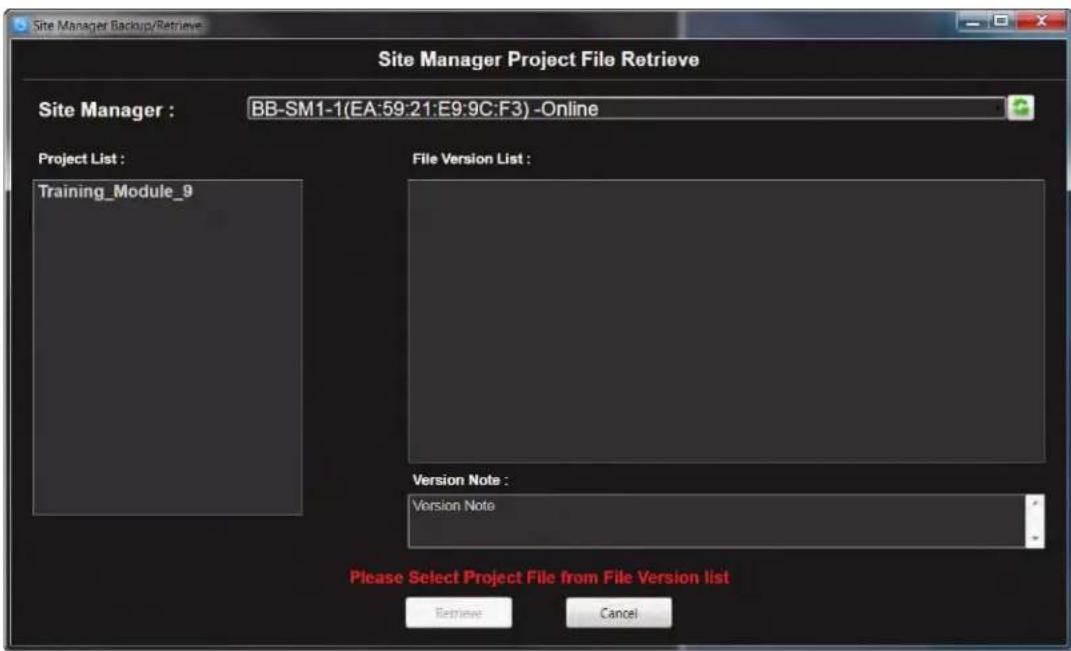
Figure 66

Atlas Sound
1601 Jack McKay Blvd. • Ennis, Texas 75119 U.S.A.
Telephone: 800.876.3333 • Fax: 800.765.3435
Select the file from the project list. (Fig 67)
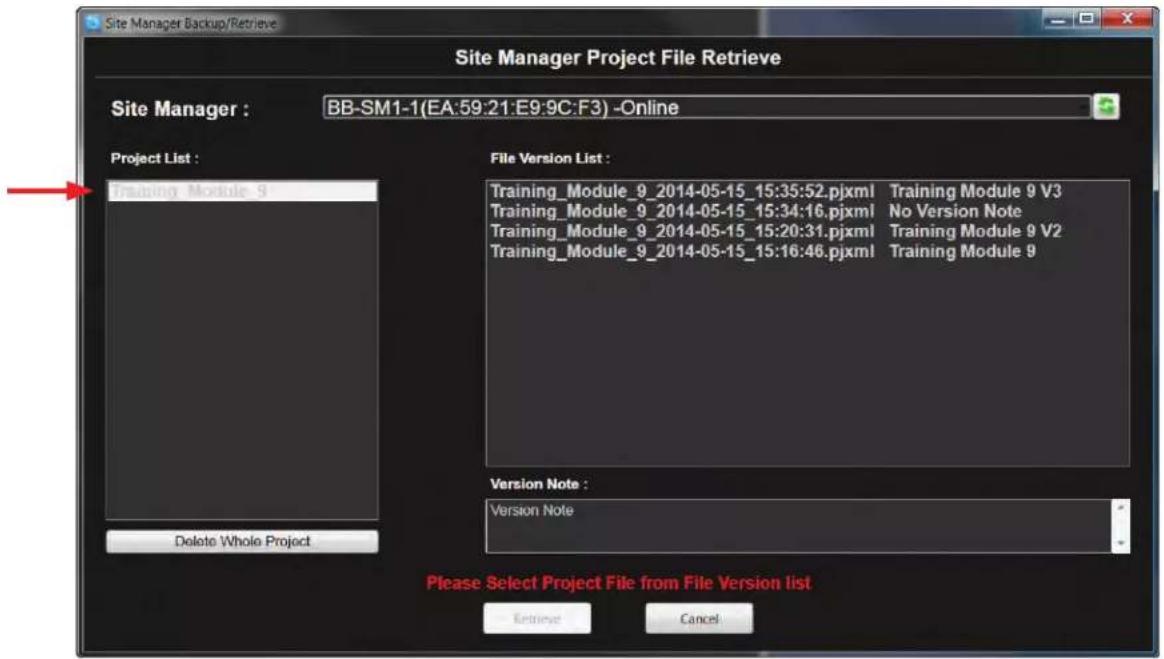
Figure 67
Choose a file version that you want to retrieve and select the "retrieve" button. (Fig 68)
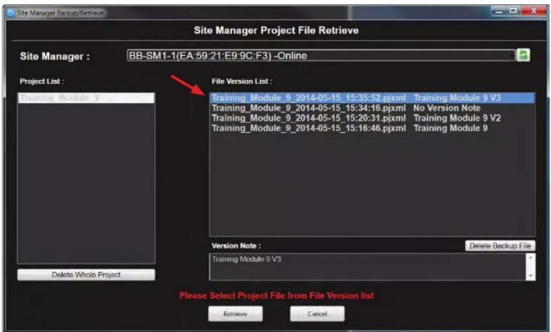
Figure 68
Save the design file with name and desired location (Fig 69), and a popup window will confirm the retrieval process. (Fig 69.1)
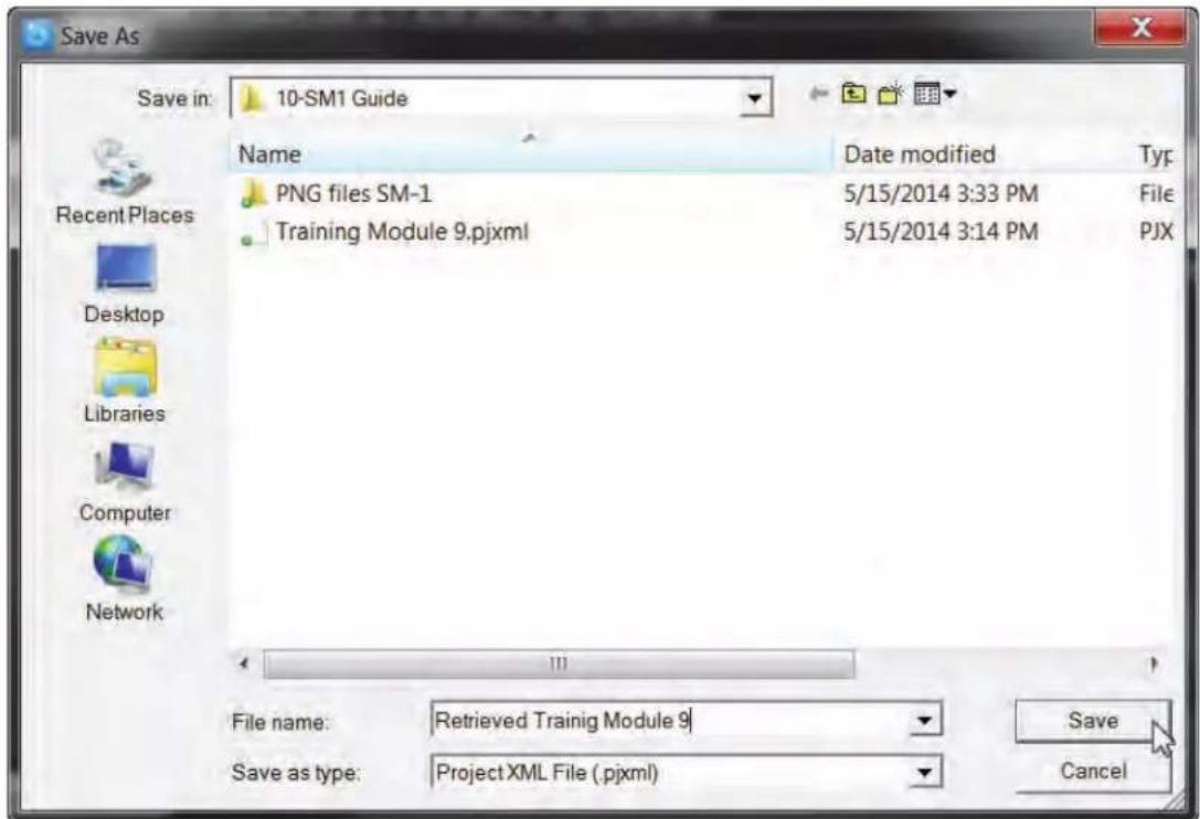
Figure 69
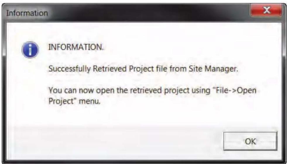
Figure 69.1

Atlas Sound
1601 Jack McKay Blvd. • Ennis, Texas 75119 U.S.A.
Telephone: 800.876.3333 • Fax: 800.765.3435
Close the Backup/ Retrieve window. (Fig 70)
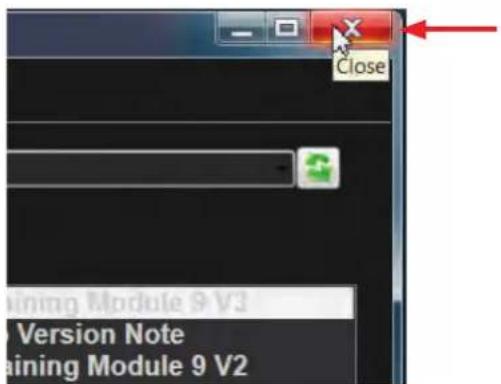
Figure 70
In BlueBridge ^® Designer, use the file menu to open the retrieved file. (Fig 71 and Fig 71.1)
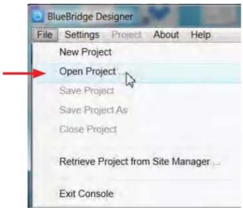
Figure 71
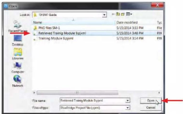
Figure 71.1
Network View
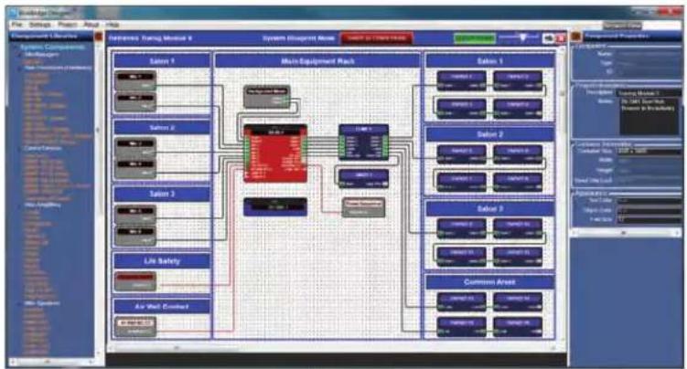
The File has been restored. (Fig 72)
flowchart
graph TD
    A["Main Equipment Rack"] --> B["Salon 1"]
    A --> C["Salon 2"]
    A --> D["Salon 3"]
    A --> E["Salon 4"]
    A --> F["Salon 5"]
    A --> G["Salon 6"]
    A --> H["Salon 7"]
    A --> I["Salon 8"]
    A --> J["Salon 9"]
    A --> K["Salon 10"]
    A --> L["Air Wall Covered"]
    style A fill:#f9f,stroke:#333
    style B fill:#ccf,stroke:#333
    style C fill:#ccf,stroke:#333
    style D fill:#ccf,stroke:#333
    style E fill:#ccf,stroke:#333
    style F fill:#ccf,stroke:#333
    style G fill:#ccf,stroke:#333
    style H fill:#ccf,stroke:#333
    style I fill:#ccf,stroke:#333
    style J fill:#ccf,stroke:#333
    style K fill:#ccf,stroke:#333
    style L fill:#ccf,stroke:#333
Figure 72
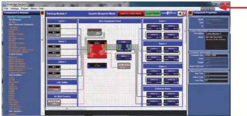
To understand the functions of the BB-SM1 in the Network View, find the Network View button at the top right section of the System BluePrint Mode page. (Fig 73 and Fig 73.1)
flowchart
graph TD
    A["Main Equipment Model"] --> B["Subunit 1"]
    A --> C["Subunit 2"]
    A --> D["Subunit 3"]
    A --> E["Subunit 4"]
    A --> F["Subunit 5"]
    A --> G["Subunit 6"]
    A --> H["Subunit 7"]
    A --> I["Subunit 8"]
    A --> J["Subunit 9"]
    A --> K["Subunit 10"]
    A --> L["Subunit 11"]
    A --> M["Subunit 12"]
    A --> N["Subunit 13"]
    A --> O["Subunit 14"]
    A --> P["Subunit 15"]
    A --> Q["Subunit 16"]
    A --> R["Subunit 17"]
    A --> S["Subunit 18"]
    A --> T["Subunit 19"]
    A --> U["Subunit 20"]
    A --> V["Subunit 21"]
    A --> W["Subunit 22"]
    A --> X["Subunit 23"]
    A --> Y["Subunit 24"]
    A --> Z["Subunit 25"]
    A --> AA["Subunit 26"]
    A --> AB["Subunit 27"]
    A --> AC["Subunit 28"]
    A --> AD["Subunit 29"]
    A --> AE["Subunit 30"]
    A --> AF["Subunit 31"]
    A --> AG["Subunit 32"]
    A --> AH["Subunit 33"]
    A --> AI["Subunit 34"]
    A --> AJ["Subunit 35"]
    A --> AK["Subunit 36"]
    A --> AL["Subunit 37"]
    A --> AM["Subunit 38"]
    A --> AN["Subunit 39"]
    A --> AO["Subunit 40"]
    A --> AP["Subunit 41"]
    A --> AQ["Subunit 42"]
    A --> AR["Subunit 43"]
    A --> AS["Subunit 44"]
    A --> AT["Subunit 45"]
    A --> AU["Subunit 46"]
    A --> AV["Subunit 47"]
    A --> AW["Subunit 48"]
    A --> AX["Subunit 49"]
    A --> AY["Subunit 50"]
    A --> AZ["Component Projectors"]
    B --> BA["Main Equipment Model"]
    C --> BB["Main Equipment Model"]
    D --> BC["Main Equipment Model"]
    E --> BD["Main Equipment Model"]
    F --> BE["Main Equipment Model"]
    G --> BF["Main Equipment Model"]
    H --> BG["Main Equipment Model"]
    I --> BH["Main Equipment Model"]
    J --> BI["Main Equipment Model"]
    K --> BJ["Main Equipment Model"]
    L --> BK["Main Equipment Model"]
    M --> BL["Main Equipment Model"]
    N --> BM["Main Equipment Model"]
    O --> BN["Main Equipment Model"]
    P --> BO["Main Equipment Model"]
    Q --> BP["Main Equipment Model"]
    R --> BQ["Main Equipment Model"]
    S --> BR["Main Equipment Model"]
    T --> BS["Main Equipment Model"]
    U --> BT["Main Equipment Model"]
    V --> BU["Main Equipment Model"]
    W --> BV["Main Equipment Model"]
    X --> BW["Main Equipment Model"]
    Y --> BX["Main Equipment Model"]
Figure 73
Select the Network View button.
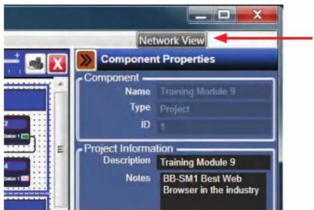
Figure 73.1

Atlas Sound
1601 Jack McKay Blvd. • Ennis, Texas 75119 U.S.A.
Telephone: 800.876.3333 • Fax: 800.765.3435
The Network View shows all BlueBridge ^® hardware that is on the Network. Locate the BB-SM1 hardware block and right click on the block to show its properties. Select Device Setup. (Fig 74)
Device Setup allows a user to change the hardware name, setup the IP configuration, setup password protection for the hardware, set time zone and clock source, and perform network testing.
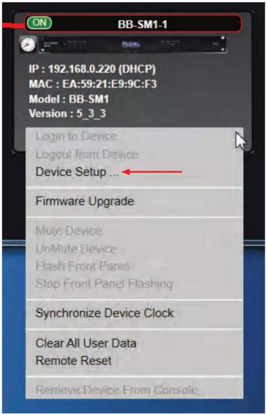
Figure 74
The Device Setup window will come up and changes can be performed. (Fig 75)
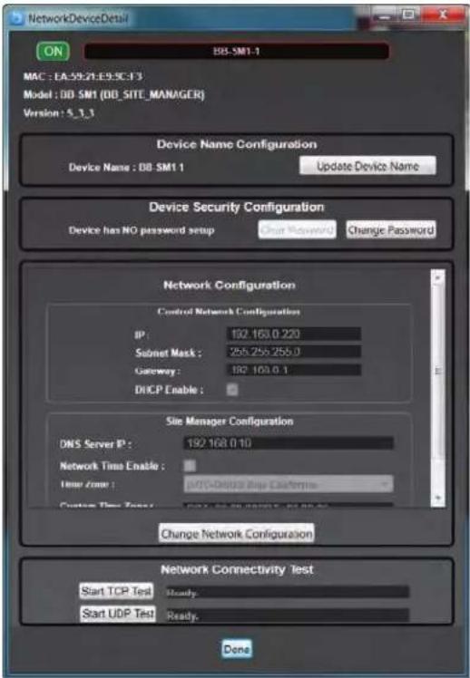
Figure 75
If "Update Device Name" is selected, a popup box will appear with a field for the new name to be entered. (Fig 76) Type in the desired name and select OK.
Note: The device name MUST match the device name on the BluePrint design page.
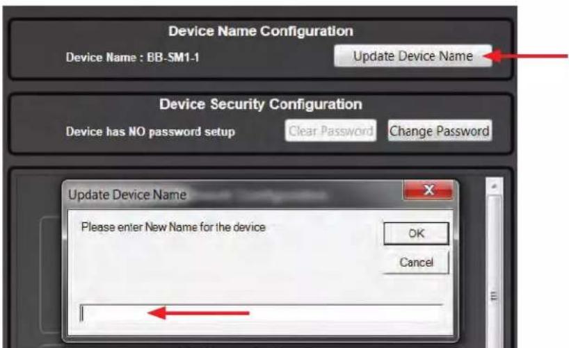
Figure 76

Atlas Sound
1601 Jack McKay Blvd. • Ennis, Texas 75119 U.S.A.
Telephone: 800.876.3333 • Fax: 800.765.3435
To setup device security for the BB-SM1 hardware select "Change Password" in the Device Security Configuration box. A popup window will appear. (Fig 77)
Enter the new password and select "OK". Note: A password is limited to 1-8 characters.
Select "Clear Password" to remove a previously setup Password.
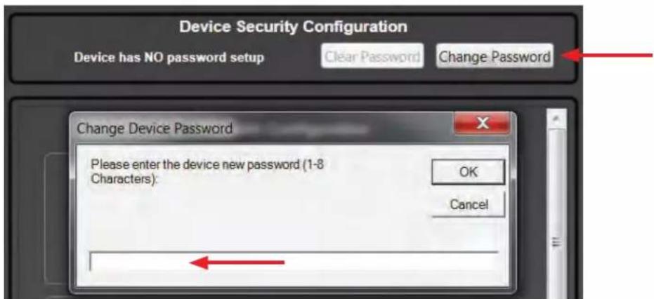
Figure 77
In the Network Configuration section under "Network Configuration", changes can be made to the IP scheme including setting up a static or DHCP configuration. Select the "Change Network Configuration" button towards the bottom of the box. (Fig 78) The IP scheme in the Control Network Configuration section will turn to white characters and the DHCP enable check box will be available for use. Make the necessary changes and select Apply. (Fig 78.1)
Note: BlueBridge ^® hardware is configured for DHCP from the factory.
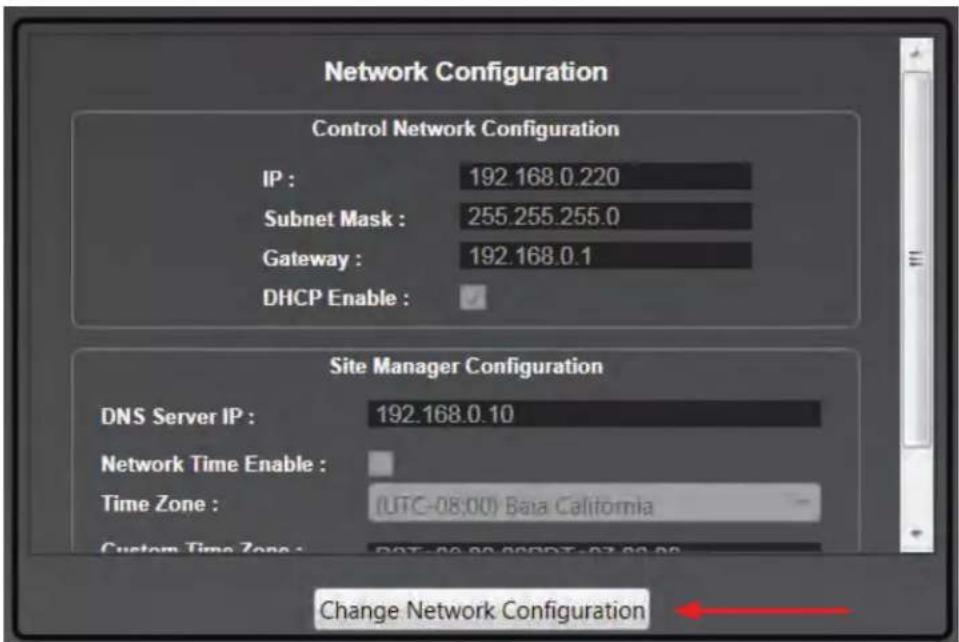
Figure 78
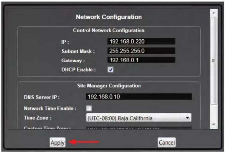
Figure 78.1
In the Site Manager Configuration section changes can be made to the hardware for the purpose of scheduling.
A DNS Server IP can be applied. Network Time can be enabled and a time zone can be selected as well as daylight savings time. (Fig 79)
Select the Change Network Configuration button towards the bottom of the box. Once changes have been made, select Apply.
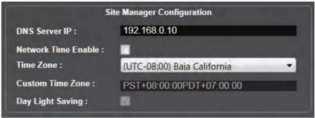
Figure 79
A Network Connectivity Test can also be performed.
Basic connectivity checking to the hardware by way of TCP and UDP testing can be done. Select from one of the "Start Test" buttons. (Fig 80)

Figure 80

Atlas Sound
1601 Jack McKay Blvd. • Ennis, Texas 75119 U.S.A.
Telephone: 800.876.3333 • Fax: 800.765.3435
The results will be displayed as in. (Fig 80.1)
If the tests are unsuccessful, there is a problem with the network setup that will need to be fixed before the hardware will work properly.

Figure 80.1
A yellow triangle on the BB-SM1 hardware block, indicates an outdated firmware version. (Fig 81.5)
The current version is listed in the block.
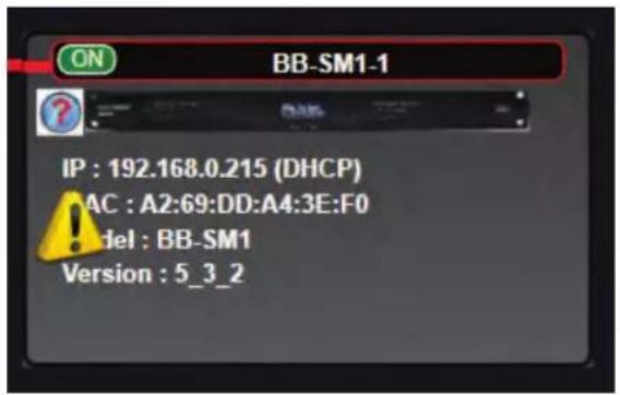
Figure 81.5
To upgrade the Firmware, begin by right clicking on the Hardware Block and selecting "Firmware Upgrade". (Fig 81)
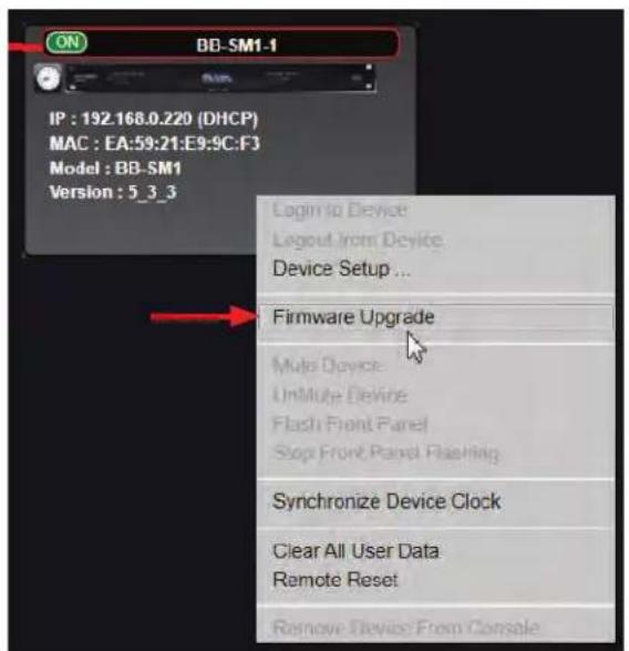
Figure 81
Follow the prompts. (Fig 81.1)
Note: Firmware Upgrades can take up to 15 minutes. Be patient and do not stop the process until the software completes the update.
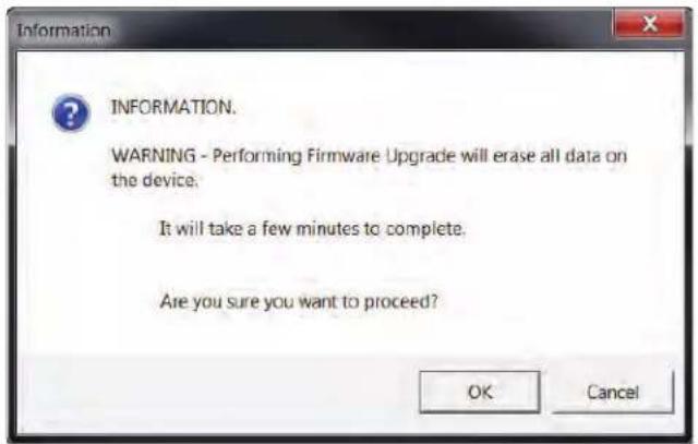
Figure 81.1
The next window will prompt the user to select a zip file from the firmware folder. If no firmware has been downloaded, it can be found at atmosphere.com/BlueBridge in the downloads section.
The BB-SM1 firmware is a zip file and should not be unzipped for this function. Select the folder and select Open. (Fig 81.2)
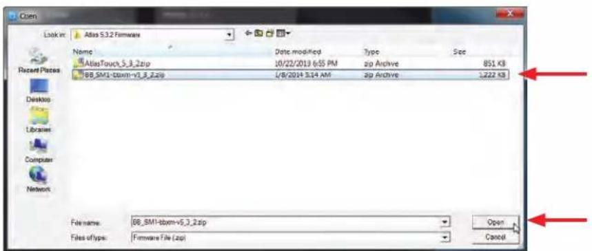
Figure 81.2
The load process will begin and progress will be illustrated in the upper section of the Hardware Block. (Fig 81.3)
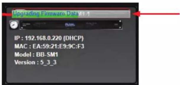
Figure 81.3

Atlas Sound
1601 Jack McKay Blvd. • Ennis, Texas 75119 U.S.A.
Telephone: 800.876.3333 • Fax: 800.765.3435
The last phase of the Upgrade will show this message. (Fig 81.4)
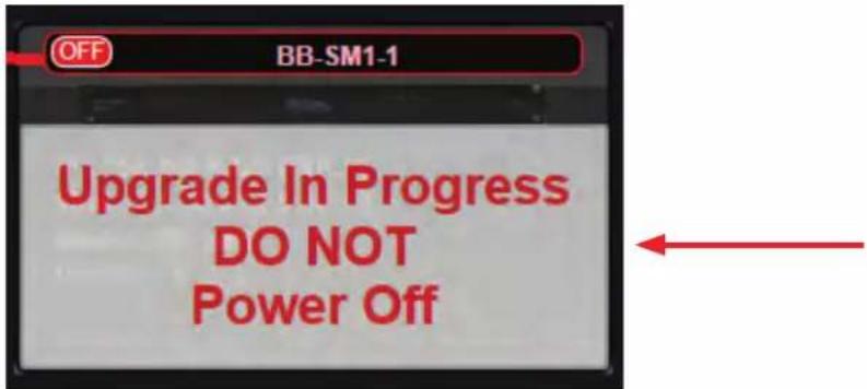
Figure 81.4
When the Upgrade is complete, the indicator in the upper left corner of the Hardware Block will be green and read "ON".
When the BB-SM1 is online the Hardware Block will show a clock icon in the upper left corner. (Fig 82.4)
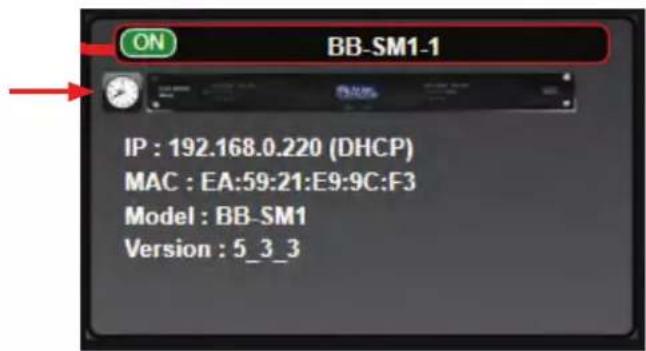
Figure 82.4
If there is a question mark (?) in the place of the Clock icon, the clock needs to be synchronized. (Fig 82.3)
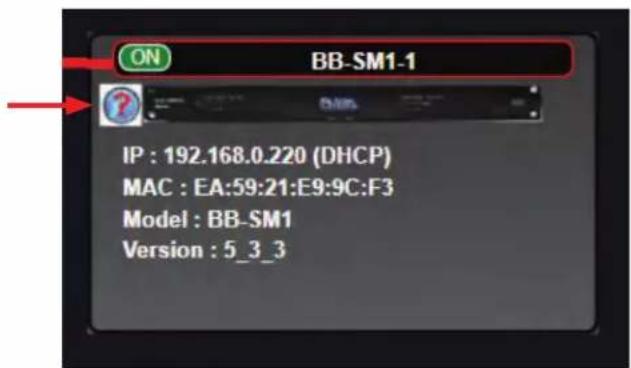
Figure 82.3
To synchronize the device clock, right click on the Hardware Block and select "Synchronize Device Clock". (Fig 82.1)
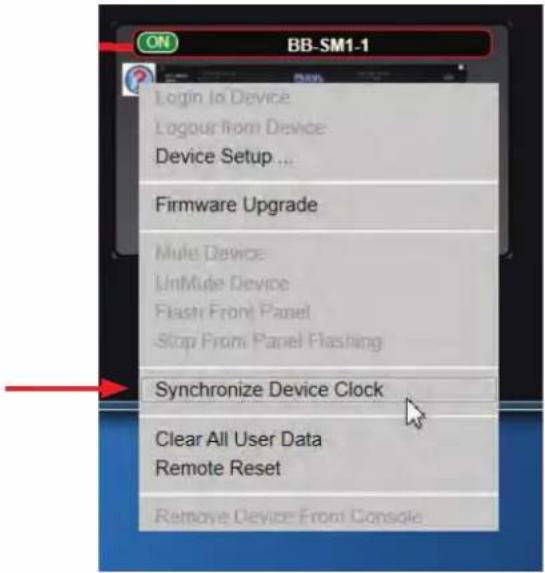
Figure 82.1
A window will pop up with the time information of the connected computer and ask to proceed. (Fig 82.2)
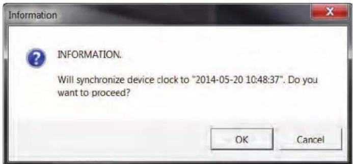
Figure 82.2
Select OK and that will complete the process. The Clock will appear in the Hardware Block. (Fig 82.4)
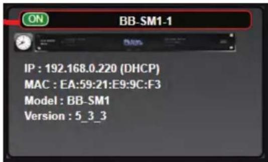
Figure 82.4

Atlas Sound
1601 Jack McKay Blvd. • Ennis, Texas 75119 U.S.A.
Telephone: 800.876.3333 • Fax: 800.765.3435
To clear out all user data in the BB-SM1, begin by right clicking on the Hardware Block, and selecting "Clear All User Data". (Fig 83) This will wipe the hardware clean and create a new starting point.
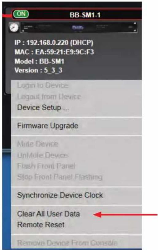
Figure 83
A window will pop up to give a final warning before you proceed. (Fig 84)
Select OK to clear all user data.
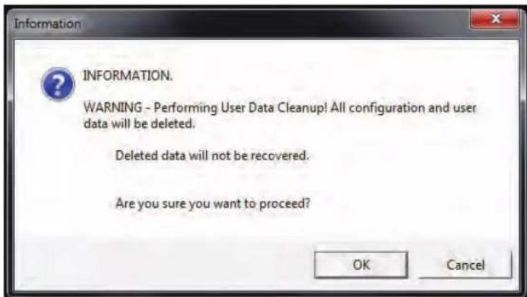
Figure 84
A remote reset can be performed on the hardware when there are connection problems with the network.
To run a remote reset, begin by right clicking on the Hardware Block, and selecting "Remote Reset". (Fig 85)
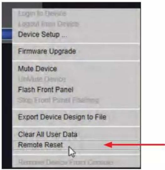
Figure 85
An information window will pop up and ask to proceed. (Fig 86)
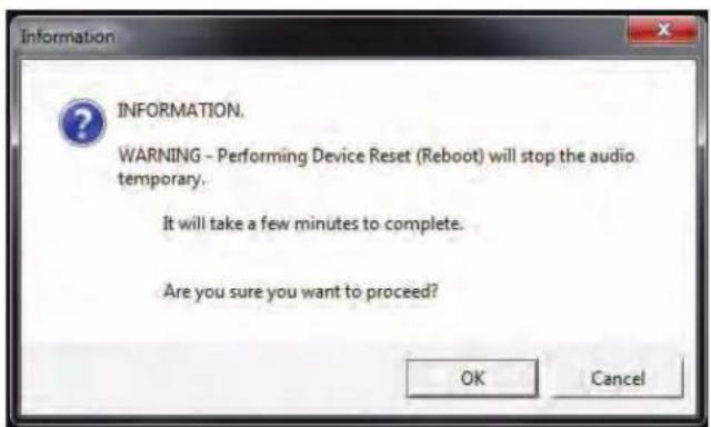
Figure 86
Visit atlassound.com/BlueBridge for the most up to date information and to learn more about BlueBridge® DSP products. Additionally, register to take training courses that provide in depth looks at how BlueBridge® hardware and software operate.
Limited Warranty
All products manufactured by Atlas Sound are warranted to the original dealer/installer, industrial or commercial purchaser to be free from defects in material and workmanship and to be in compliance with our published specifications, if any. This warranty shall extend from the date of purchase for a period of three years on all Atlas Sound products, including SOUNDOLIER brand, and ATLAS SOUND brand products except as follows: one year on electronics and control systems; one year on replacement parts; and one year on Musician Series stands and related accessories. Additionally, fuses and lamps carry no warranty. Atlas Sound will solely at its discretion, replace at no charge or repair free of charge defective parts or products when the product has been applied and used in accordance with our published operation and installation instructions. We will not be responsible for defects caused by improper storage, misuse (including failure to provide reasonable and necessary maintenance), accident, abnormal atmospheres, water immersion, lightning discharge, or malfunctions when products have been modified or operated in excess of rated power, altered, serviced or installed in other than a workman like manner. The original sales invoice should be retained as evidence of purchase under the terms of this warranty. All warranty returns must comply with our returns policy set forth below. When products returned to Atlas Sound do not qualify for repair or replacement under our warranty, repairs may be performed at prevailing costs for material and labor unless there is included with the returned product(s) a written request for an estimate of repair costs before any nonwarranty work is performed. In the event of replacement or upon completion of repairs, return shipment will be made with the transportation charges collect.
EXCEPT TO THE EXTENT THAT APPLICABLE LAW PREVENTS THE LIMITATION OF CONSEQUENTIAL DAMAGES FOR PERSONAL INJURY, ATLAS SOUND SHALL NOT BE LIABLE IN TORT OR CONTRACT FOR ANY DIRECT, CONSEQUENTIAL OR INCIDENTAL LOSS OR DAMAGE ARISING OUT OF THE INSTALLATION, USE OR INABILITY TO USE THE PRODUCTS. THE ABOVE WARRANTY IS IN LIEU OF ALL OTHER WARRANTIES INCLUDING BUT NOT LIMITED TO WARRANTIES OF MERCHANTABILITY AND FITNESS FOR A PARTICULAR PURPOSE.
Atlas Sound does not assume, or does it authorize any other person to assume or extend on its behalf, any other warranty, obligation, or liability. This warranty gives you specific legal rights and you may have other rights which vary from state to state.
Service
Should your BB-SM1 require service, please contact the Atlas Sound warranty department at 1-877-689-8055, ext. 277 to obtain an RA number.
Atlas Sound Tech Support can be reached at 1-800-876-3333.
Visit our website at www.AtlasSound.com to see other Atlas products.
©2015 Atlas Sound L.P. All rights reserved. Atlas Sound is a trademark of Atlas Sound L.P. All other trademarks are the property of their respective owners. ATS005142 RevA 3/15
Brand : Atlas Sound
Model : BlueBridge BB-SM1
Category : Hi-Fi System