SmartRack SRWF4U36 - IT cabinet Tripp Lite - Free user manual and instructions
Find the device manual for free SmartRack SRWF4U36 Tripp Lite in PDF.

User questions about SmartRack SRWF4U36 Tripp Lite
0 question about this device. Answer the ones you know or ask your own.
Ask a new question about this device
Download the instructions for your IT cabinet in PDF format for free! Find your manual SmartRack SRWF4U36 - Tripp Lite and take your electronic device back in hand. On this page are published all the documents necessary for the use of your device. SmartRack SRWF4U36 by Tripp Lite.
USER MANUAL SmartRack SRWF4U36 Tripp Lite
Low-Profile Wall-Mount SmartRack® Enclosures
Models: SRWF2U, SRWF2U36, SRWF4U, SRWF4U36, SRWF5U, SRWF5U36, SRWF6U, SRWF6U36
Table of Contents
- Important Safety Instructions 2
- Overview 2
- Feature Identification 3
- Enclosure Installation 4
4.1 Preparation 4
4.2 Unpacking 4
- Enclosure Configuration 5
5.1 Door Locks 5
5.2 Cable Access & Management 5
5.3 Reversing the Front Door 5
5.4 Mounting Rails 6
5.5 Adjusting Mounting Rail Depth 6
- Wall Mounting the Enclosure 6
6.1 Mounting 6 - Equipment Installation 7
- Optional Patch Panel Installation 7
- Specifications 7
- Storage & Service 8
- Warranty & Product Registration 8
Español 9
PROTECT YOUR INVESTMENT!
Register your product for quicker service and ultimate peace of mind.
You could also win an ISOBAR6ULTRA surge protector—a \$100 value!
www.tripplite.com/warranty


text_image
TRIPP·LITE
1. Important Safety Instructions
SAVE THESE INSTRUCTIONS
This Manual contains instructions and warnings that must be followed during the installation and operation of the product described in this manual. Failure to comply may invalidate the warranty and cause property damage or personal injury.
- Keep the enclosure in a controlled indoor environment, away from moisture, temperature extremes, flammable liquids and gasses, conductive contaminants, dust and direct sunlight.
- Leave adequate space at the front and rear of the enclosure for proper ventilation. Do not block, cover or insert objects into the external ventilation openings of the enclosure.
- The enclosure is extremely heavy. Use caution when handling the enclosure. Do not attempt to unpack, move or install it unassisted. Use a mechanical device such as a forklift or pallet jack to move the enclosure in the shipping container.
- Do not place any object on the enclosure, especially containers of liquid, and do not attempt to stack the enclosures.
- Inspect the shipping container and the enclosure for shipping damage. Do not use the enclosure if it is damaged.
- Leave the enclosure in the shipping container until it has been moved as close to the final installation location as possible.
- Install the enclosure in a structurally sound area capable of handling the load, or on a level floor that is able to bear the weight of the enclosure, all equipment that will be installed in the enclosure and any other enclosures and/or equipment that will be installed nearby.
- Use caution when cutting packing materials. The enclosure could be scratched, causing damage not covered by the warranty.
- Save all packing materials for later use. Repacking and shipping the enclosure without the original packing materials may cause product damage that will void the warranty.
- Do not reship the enclosure with additional equipment unless the enclosure was shipped with a special shock pallet ("SP1" models only). The combined weight of the enclosure and installed equipment must not exceed the load capacity of the pallet. Tripp Lite is not responsible for any damage that occurs during reshipment.
- Use of this equipment in life support applications where failure of this equipment can reasonably be expected to cause the failure of the life support equipment or to significantly affect its safety or effectiveness is not recommended. Do not use this equipment in the presence of a flammable anesthetic mixture with air, oxygen or nitrous oxide.
2. Overview
These Low-Profile Wall-Mount SmartRack Enclosures provide convenient and secure vertical mounting for standard 19-inch rackmount equipment, regardless of vendor, and ship fully assembled for quick and easy deployment.
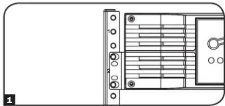
3. Feature Identification
text_image
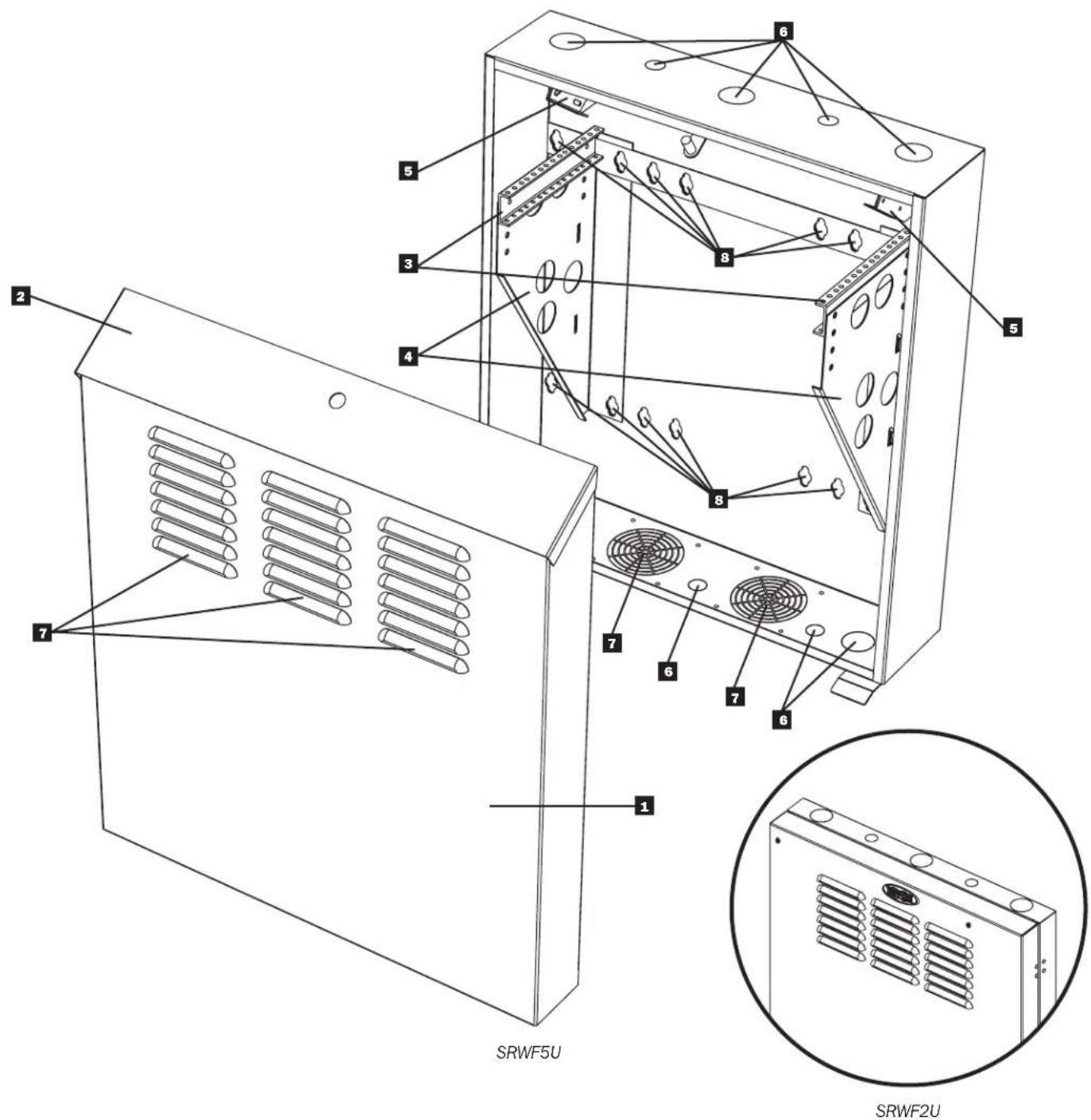
SRWF5U SRWF2UFeatures for all other models are similar, except the SRWF2U series does not have a top panel door.
1 Front Door
2 Top Panel Door
3 Horizontal Mounting Rails
4 Vertical Mounting Bracket
5 Patch Panel Mounting Bracket
6 Cable Access Holes
7 Vents
8 Wall-Mounting Slots
4. Enclosure Installation

Caution! Read All Instructions and Warnings Before Installation!

Warning: Rack enclosures can be extremely heavy. Do not attempt to unpack, move or install the enclosure without assistance. Use extreme caution when handling the enclosure and be sure to follow all handling and installation instructions. Do not attempt to install equipment without first stabilizing the enclosure.
4.1 Preparation
The enclosure must be installed in a structurally sound area that is able to bear the weight of the enclosure, all the equipment that will be installed in the enclosure and any other enclosures and/or equipment that will be installed nearby. Before unpacking the enclosure, you should transport the shipping container closer to the final installation location to minimize the distance you will need to move the unit after the protective packaging has been removed. If you plan to store the enclosure for an extended period before installation, follow the instructions in the Storage and Service section.
You need several tools:
- Level
• Phillips-head Screwdriver - Appropriate tools for wall mounting
You also need the following hardware:
- Appropriate hardware for wall mounting (not included)
4.2 Unpacking

Use at least two people to unpack the enclosure.

1 Move shipping pallet to a firm, level surface.
2 Open box and remove the four foam corner protectors. Save all packing materials for later use unless you are certain they will not be required. Packing materials are recyclable.
3 With one person on each side, carefully lift the enclosure out of the box and place on a firm, level surface.
4 Examine the enclosure for any damage or loose parts. Confirm all parts are present. If anything is missing or damaged, contact Tripp Lite for assistance. Do not attempt to use the enclosure if it has been damaged.

Never extend more than one component from the enclosure at a time.


Warning: Never attempt to lift or install without adequate help. Do not try lifting the enclosure alone.

5. Enclosure Configuration
Before installation, be sure to plan the location and arrangement of components within the enclosure. Be sure all mounting rails are reversed or adjusted for depth, depending on your equipment configuration.
5.1 Door Locks
The SRWF2U series models have one lock on the side of the unit that's accessible by the included key. The SRWF4U, SRWF5U and SRWF6U series models have locks on the front door and the top panel door that are accessible by included keys. All models have a front door latch that can be locked with a user-supplied padlock for extra security.

natural_image
Diagram of a device with a key inserted into a panel, showing a close-up of its key and a dashed arrow indicating the direction (no text or symbols present)
text_image
SRWF5U shownSRWF2U sh5.2 Cable Access and Management
The top and bottom panels of the enclosure both have circular cable access ports for convenient cable management. The tops of all models have three 1.75" ports and two 1" ports. The bottoms of SRWF2U and SRWF4U series models have two 1" and 1.75" ports, while the SRWF5U and SRWF6U series models have three 1" ports and two 1.75" ports.

natural_image
Technical line drawing of a dual-chamber electronic component with no text or symbols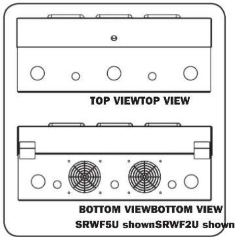
text_image
TOP VIEWTOP VIEW BOTTOM VIEWBOTTOM VIEW SRWF5U shownSRWF2U shown5.3 Reversing the Front Door
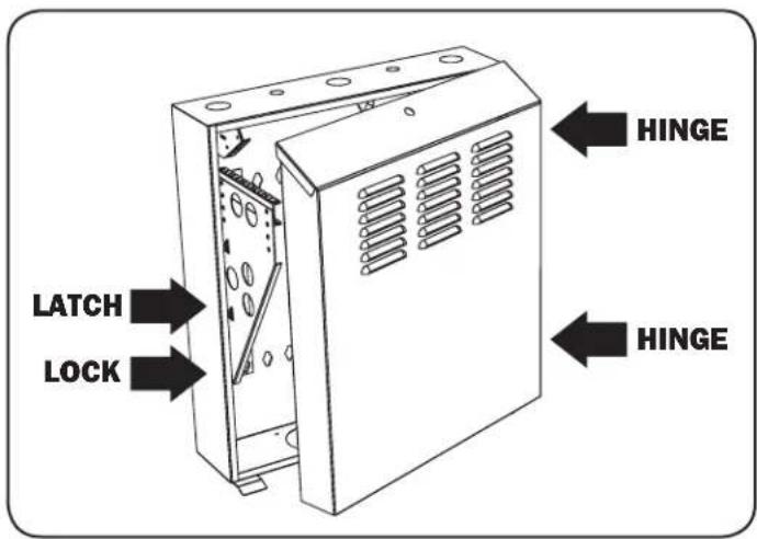
In order to accommodate various rack installations, the front door can be reversed by switching the configuration of its latch, lock and hinges. To reverse the door, simply remove the screws that secure the latch, lock and hinges to the enclosure. Move each piece to the opposite side of the enclosure, so that there are two hinges on one side (one at the top, one at the bottom) and the latch and the lock on the other side.
Note: The unused screw holes are filled with rubber placeholders. To remove the placeholders, push them through with a screwdriver. Keep the placeholders to refill unused screw holes.
text_image
LATCH LOCK HINGE HINGE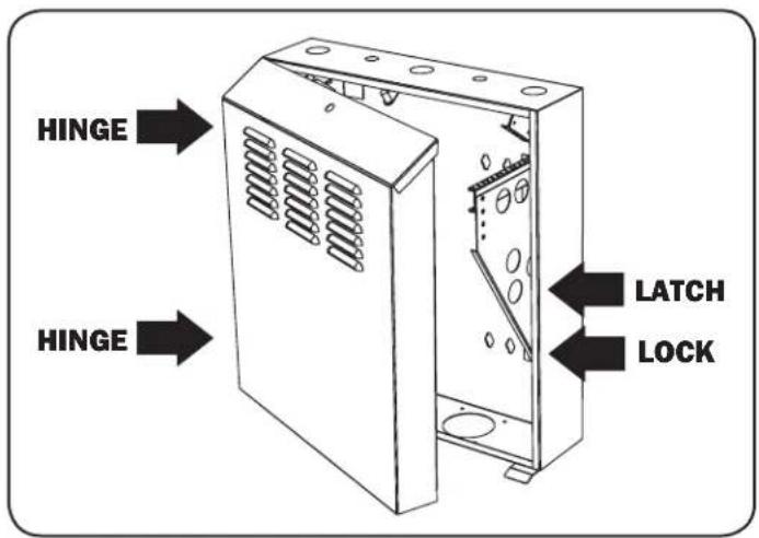
text_image
HINGE HINGE LATCH LOCK5. Enclosure Configuration (continued)
5.4 Mounting Rails
The enclosure comes with reversible horizontal mounting rails that have threaded holes for mounting rack equipment. The holes on one side of the rail are threaded for M6 hardware, while the holes on the other side are threaded for 12-24. Orient the rails so the hole type you need is on top. To install equipment, use the included M6 or 12-24 hardware to secure equipment to the rails. (See the following page for equipment installation instructions.) Warning: Be sure to have the enclosure securely mounted to the wall, or in its final position on the floor before mounting any equipment inside. Also be sure to have all the right adjustments on your rails before mounting equipment. (See below for Adjusting Mounting Rail Depth.)

text_image
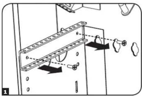
M6 12-245.5 Adjusting Mounting Rail Depth
Warning: Do not attempt to adjust rails while equipment is installed in the enclosure. Do not attempt to use rails without screws installed. (2 per rail.)
The two horizontal mounting rails are pre-installed to accommodate equipment with a mounting depth of 20 inches (508 mm). Do not adjust the mounting rails unless your equipment requires a different mounting depth. The rails can be adjusted in 1-inch increments for mounting depths between 17 inches (432 mm) and 20 inches (508 mm).
1 Each rail is connected to the enclosure with 2 screws: 1 at the front of the enclosure and one at the rear. Using a Philips-head screwdriver, remove the screws that fasten the rails to the enclosure.
2 Slide the mounting rails vertically to the desired depth and reattach them using the screws you removed in Step 1.
text_image
Technical diagram showing mechanical assembly with labeled components and motion indicators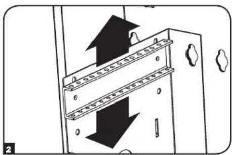
natural_image
Diagram of a door mechanism with arrows indicating movement, no text or symbols present6. Wall Mounting the Enclosure
Warning: Do not attempt to mount the enclosure to the wall with equipment mounted in the enclosure.
6.1 Mounting
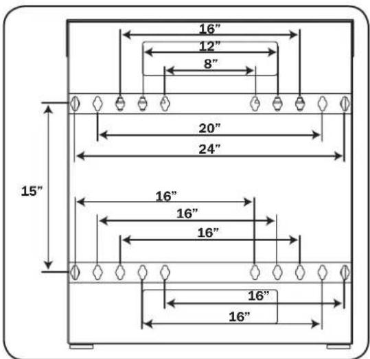
There are 20 keyhole cutouts on the back door of the enclosure arranged in 4 sets of 5. Each keyhole can accommodate an M10 or 3/8" bolt. The holes are on 16" centers, with the holes in each set 2" apart from center to center. Holes are then 15" apart vertically, as shown in the diagram.
Using a level, measure to position your mounting areas precisely. Use appropriate fasteners (not included) to secure the enclosure to the wall. A minimum of four fasteners and appropriately-sized fender washers is recommended. Warning: The area you plan to mount the enclosure to must be able to withstand the weight of the enclosure and all mounted equipment. For the weight of the enclosure and its capacity, see the Specifications section.
text_image
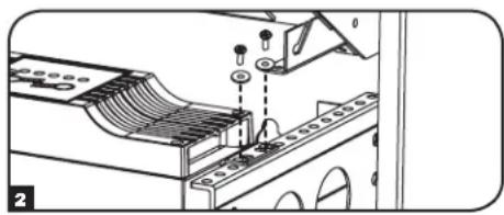
16" 12" 8" 20" 24" 15" 16" 16" 16" 16" 16"7. Equipment Installation
Warning: Do not install equipment until you have stabilized the enclosure. If using sliding equipment rails, be careful when extending the rails. Do not extend more than one set of sliding equipment rails at one time. Avoid extending sliding equipment rails near the top of the enclosure.
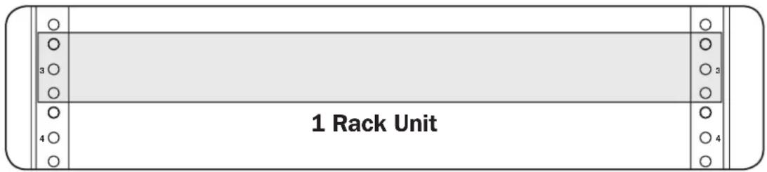
Note: The threaded holes in the middle of each rack unit are numbered. A single rack unit includes the space occupied by the numbered hole and the holes directly above and below.
text_image
1 Rack UnitWARNING: Follow the instructions in your equipment documentation to ensure proper installation of your equipment.
1 Locate the numbered openings in the mounting rails where you plan to install your equipment. Lower your equipment into the enclosure and set it down on the mounting rails, lining up the mounting holes on the equipment with the mounting rail's mounting holes.
natural_image
Technical line drawing of a mechanical or electronic component with no visible text, numbers, or symbols2 Use the included mounting screws and washers to secure your equipment to the rack rail. Place the washers between the screws and the equipment mounting brackets.
Note: Your equipment may also include mounting hardware. Read the mounting instructions that came with your equipment before installing your equipment.
natural_image
Technical diagram of a mechanical assembly with no visible text or symbols8. Optional Patch Panel Installation
The unit comes with an integral, slide-out mounting bracket at the top of the enclosure. It can be used to secure a patch panel to the enclosure, and it partially slides out for easier cabling access. To install a patch panel on the patch panel mounting bracket, use the included mounting screws and washers to secure your equipment to the rack rail. Place the washers between the screws and the patch panel mounting bracket.

natural_image
Diagram showing five sequential steps of a mechanical bracket assembly (no text or symbols)9. Specifications
| Model Dimensions (HxWxD) Unit Weight Load Capacity* Mounting Depth (Adjustable) | ||||
| SRWF2U | 28.8" x 25.6" x 4.5" (732 x 651 x 114 mm) | 41.9 lb (19 kg) | 150 lb (68.1 kg) | 17" to 20" (432 to 508 mm) |
| SRWF2U36 | 43" x 25.6" x 4.5" (1092 x 651 x 114 mm) | 59.5 lb (27 kg) | 150 lb (68.1 kg) | 33" to 36" (838 to 914 mm) |
| SRWF4U | 28.8" x 25.6" x 8" (732 x 651 x 203 mm) | 44.1 lb (20 kg) | 150 lb (68.1 kg) | 17" to 20" (432 to 508 mm) |
| SRWF4U36 | 43" x 25.6" x 8" (1092 x 651 x 203 mm) | 61.7 lb (28 kg) | 150 lb (68.1 kg) | 33" to 36" (838 to 914 mm) |
| SRWF5U | 28.8" x 25.6" x 9.7" (732 x 651 x 247 mm) | 45 lb (20.4 kg) | 150 lb (68.1 kg) | 17" to 20" (432 to 508 mm) |
| SRWF5U36 | 43" x 25.6" x 9.7" (1092 x 651 x 247 mm) | 55 lb (25 kg) | 150 lb (68.1 kg) | 33" to 36" (838 to 914 mm) |
| SRWF6U | 28.8" x 25.6" x 11.5" (732 x 651 x 292 mm) | 55.1 lb (25 kg) | 150 lb (68.1 kg) | 17" to 20" (432 to 508 mm) |
| SRWF6U36 | 43" x 25.6" x 11.5" (1092 x 651 x 292 mm) | 77.2 lb (35 kg) | 150 lb (68.1 kg) | 33" to 36" (838 to 914 mm) |
* Full wall-mount load capacity requires a mounting surface capable of bearing the full load.
10. Storage & Service
Storage
The enclosure should be stored in a controlled indoor environment, away from moisture, temperature extremes, flammable liquids and gasses, conductive contaminants, dust and direct sunlight. Store the enclosure in its original shipping container if possible.
Service
Your Tripp Lite product is covered by the warranty described in this manual. A variety of Extended Warranty and On-Site Service Programs are also available from Tripp Lite. For more information on service, visit www.triplite.com/support. Before returning your product for service, follow these steps:
- Review the installation and operation procedures in this manual to insure that the service problem does not originate from a misreading of the instructions.
- If the problem continues, do not contact or return the product to the dealer. Instead, visit www.tripplite.com/support.
- If the problem requires service, visit www.tripplite.com/support and click the Product Returns link. From here you can request a Returned Material Authorization (RMA) number, which is required for service. This simple on-line form will ask for your unit's model and serial numbers, along with other general purchaser information. The RMA number, along with shipping instructions will be emailed to you. Any damages (direct, indirect, special or consequential) to the product incurred during shipment to Tripp Lite or an authorized Tripp Lite service center is not covered under warranty. Products shipped to Tripp Lite or an authorized Tripp Lite service center must have transportation charges prepaid. Mark the RMA number on the outside of the package. If the product is within its warranty period, enclose a copy of your sales receipt. Return the product for service using an insured carrier to the address given to you when you request the RMA.
11. Warranty & Product Registration
5-Year Limited Warranty
Seller warrants this product, if used in accordance with all applicable instructions, to be free from original defects in material and workmanship for a period of 5 years from the date of initial purchase. If the product should prove defective in material or workmanship within that period, Seller will repair or replace the product, at its sole discretion.
THIS WARRANTY DOES NOT APPLY TO NORMAL WEAR OR TO DAMAGE RESULTING FROM ACCIDENT, MISUSE, ABUSE OR NEGLECT. SELLER MAKES NO EXPRESS WARRANTIES OTHER THAN THE WARRANTY EXPRESSLY SET FORTH HEREIN. EXCEPT TO THE EXTENT PROHIBITED BY APPLICABLE LAW, ALL IMPLIED WARRANTIES, INCLUDING ALL WARRANTIES OF MERCHANTABILITY OR FITNESS, ARE LIMITED IN DURATION TO THE WARRANTY PERIOD SET FORTH ABOVE; AND THIS WARRANTY EXPRESSLY EXCLUDES ALL INCIDENTAL AND CONSEQUENTIAL DAMAGES. (Some states do not allow limitations on how long an implied warranty lasts, and some states do not allow the exclusion or limitation of incidental or consequential damages, so the above limitations or exclusions may not apply to you. This warranty gives you specific legal rights, and you may have other rights which vary from jurisdiction to jurisdiction).
WARNING: The individual user should take care to determine prior to use whether this device is suitable, adequate or safe for the use intended. Since individual applications are subject to great variation, the manufacturer makes no representation or warranty as to the suitability or fitness of these devices for any specific application.
Product Registration
Visit www.triplite.com/warranty today to register your new Tripp Lite product.You'll be automatically entered into a drawing for a chance to win a FREE Tripp Lite product!*
* No purchase necessary. Void where prohibited. Some restrictions apply. See website for details.
Regulatory Compliance Identification Numbers
For the purpose of regulatory compliance certifications and identification, your Tripp Lite product has been assigned a unique series number. The series number can be found on the product nameplate label, along with all required approval markings and information. When requesting compliance information for this product, always refer to the series number. The series number should not be confused with the marketing name or model number of the product.
Tripp Lite has a policy of continuous improvement. Specifications are subject to change without notice.

text_image
TRIPP·LITE
1111 W. 35th Street, Chicago, IL 60609 USA • www.tripplite.com/support
text_image
SRWF5U SRWF2Unatural_image
Diagram of a device with a scroll panel and two key icons, showing a rotation arrow and a magnified view of the key mechanism (no text or symbols present)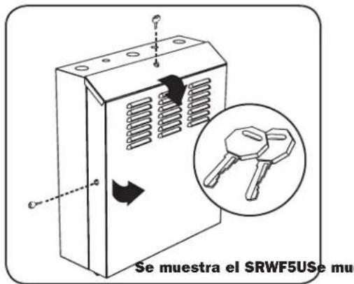
natural_image
Technical line drawing of two identical electronic component modules with no text or symbols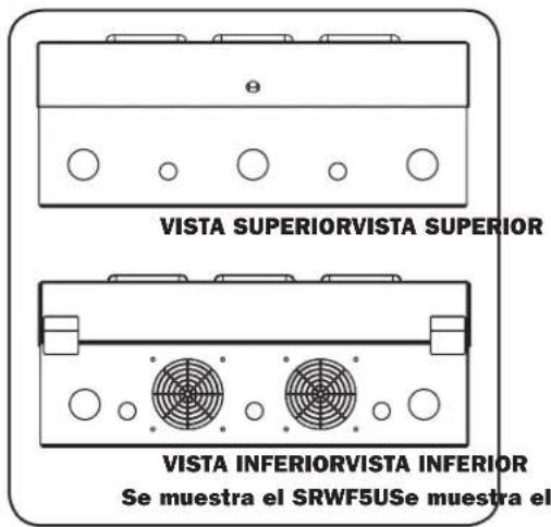
text_image
Technical diagram showing mechanical assembly with labeled components and directional arrows indicating motion or force
natural_image
Diagram showing a mechanical or electrical component with arrows indicating direction, no text or symbols presenttext_image
1 Rack Unitnatural_image
Technical line drawing of a mechanical or electronic component with no visible text, numbers, or symbols
natural_image
Technical diagram of a mechanical assembly with no visible text or symbols1111 W. 35th Street, Chicago, IL 60609 USA • www.tripplite.com/support