FHD493-XE - Projector Christie - Free user manual and instructions
Find the device manual for free FHD493-XE Christie in PDF.

User questions about FHD493-XE Christie
0 question about this device. Answer the ones you know or ask your own.
Ask a new question about this device
Download the instructions for your Projector in PDF format for free! Find your manual FHD493-XE - Christie and take your electronic device back in hand. On this page are published all the documents necessary for the use of your device. FHD493-XE by Christie.
USER MANUAL FHD493-XE Christie
text_image
User Guide 020-001381-02User Guide
020-001381-02
FHD493-XE
CHRISTIE®
NOTICES
COPYRIGHT AND TRADEMARKS
Copyright © 2019 Christie Digital Systems USA Inc. All rights reserved.
All brand names and product names are trademarks, registered trademarks or trade names of their respective holders.
GENERAL
Every effort has been made to ensure accuracy, however in some cases changes in the products or availability could occur which may not be reflected in this document. Christie reserves the right to make changes to specifications at any time without notice. Performance specifications are typical, but may vary depending on conditions beyond Christie's control such as maintenance of the product in proper working conditions. Performance specifications are based on information available at the time of printing. Christie makes no warranty of any kind with regard to this material, including, but not limited to, implied warranties of fitness for a particular purpose. Christie will not be liable for errors contained herein or for incidental or consequential damages in connection with the performance or use of this material. Manufacturing facilities in Canada and China are ISO 9001 certified. Manufacturing facilities in Canada are also ISO 14001 certified.
WARRANTY
Products are warranted under Christie's standard limited warranty, the complete details of which are available by contacting your Christie dealer or Christie. In addition to the other limitations that may be specified in Christie's standard limited warranty and, to the extent relevant or applicable to your product, the warranty does not cover:
a. Problems or damage occurring during shipment, in either direction.
b. Problems or damage caused by combination of a product with non-Christie equipment, such as distribution systems, cameras, DVD players, etc., or use of a product with any non-Christie interface device.
c. Problems or damage caused by misuse, improper power source, accident, fire, flood, lightning, earthquake, or other natural disaster.
d. Problems or damage caused by improper installation/alignment, or by equipment modification, if by other than Christie service personnel or a Christie authorized repair service provider.
e. Use of third party product enclosures for environmental protection during outside use must be approved by Christie.
f. Problems or damage caused by use of a product on a motion platform or other movable device where such product has not been designed, modified or approved by Christie for such use.
g. Except where the product is designed for outdoor use, problems or damage caused by use of the product outdoors unless such product is protected from precipitation or other adverse weather or environmental conditions and the ambient temperature is within the recommended ambient temperature set forth in the specifications for such product.
h. Image retention on LCD flat panels.
i. Defects caused by normal wear and tear or otherwise due to normal aging of a product.
The warranty does not apply to any product where the serial number has been removed or obliterated. The warranty also does not apply to any product sold by a reseller to an end user outside of the country where the reseller is located unless (i) Christie has an office in the country where the end user is located or (ii) the required international warranty fee has been paid.
The warranty does not obligate Christie to provide any on site warranty service at the product site location.
PREVENTATIVE MAINTENANCE
Preventative maintenance is an important part of the continued and proper operation of your product. Failure to perform maintenance as required, and in accordance with the maintenance schedule specified by Christie, will void the warranty.
REGULATORY
The product has been tested and found to comply with the limits for a Class A digital device, pursuant to Part 15 of the FCC Rules. These limits are designed to provide reasonable protection against harmful interference when the product is operated in a commercial environment. The product generates, uses, and can radiate radio frequency energy and, if not installed and used in accordance with the instruction manual, may cause harmful interference to radio communications. Operation of the product in a residential area is likely to cause harmful interference in which case the user will be required to correct the interference at the user's own expense.
CAN ICES-3 (A) / NMB-3 (A)
The product is designed and manufactured with high-quality materials and components that can be recycled and reused. This symbol 📄 means that electrical and electronic equipment, at their end-of-life, should be disposed of separately from regular waste. Please dispose of the product appropriately and according to local regulations. In the European Union, there are separate collection systems for used electrical and electronic products. Please help us to conserve the environment we live in!
Content
Package handling. 7
Unpacking the panel. 7
Inspecting the display panel....8
Handling and mounting guidelines for extreme narrow bezel series panels. 9
Cleaning the panel. 9
Key features. 9
Related documentation....10
Parts list. 10
Important safeguards. 1 1
General safety precautions. 1 1
AC power precautions. 1 1
Controls and functions. 12
Display at a glance. 12
Input panel. 13
Remote control unit. 14
Installing a display panel.... 16
Inserting batteries in the remote control. 16
Operating the remote control....16
Locking or unlocking the remote control. 17
Mounting a display panel....17
Securing an LCD display panel to an adjacent panel. 17
Connecting signal to the display panel. 18
Connecting to an AC power source. 18
Connecting a display panel to a control system or a computer. 19
Creating an RS232 connection.... 19
Creating an Ethernet connection. 19
Creating an IR extender connection....20
Connecting source components to a display panel. 21
Connecting a DisplayPort source. 21
Connecting an HDMI or a DVI-D source. 2 1
Connecting a VGA source. 2 2
Creating a video wall. 23
Connecting video by daisy-chaining display panels. 23
Connecting an RS232 or an Ethernet controller to a video wall in landscape orientation. . . . . 2 3
Connecting an RS232 or an Ethernet controller to a video wall in portrait orientation. . . . . . 2 4
Turning on the display panel. 25
Avoiding image retention. 25
Configuring the on-screen display.... 26
Setting the on-screen display transparency. 26
Changing the location of the on-screen display. 26
Setting the size of the on-screen display. 26
Rotating the on-screen display. 26
Changing the on-screen display language. 27
Configuring the on-screen display timeout. 27
Changing the behavior of the power LED. 27
Changing the date and time 27
Scheduling when the display is on. 27
Adjusting the image. 29
Changing the image preset. 29
Modifying the brightness. 29
Changing the contrast. 30
Sharpening the image. 30
Changing the saturation 31
Adjusting the hue of the image. 31
Changing the backlight. 32
Changing the gamma settings. 32
Calibrating the image. 32
Setting the color temperature. 32
Selecting the flesh tone. 3 3
Turning off local dimming. 3 3
Updating display settings.... 3 4
Configuring the display settings. 34
Changing the aspect ratio. 34
Setting the zoom level. 34
Enabling Auto Scan. 34
Selecting a source. 35
Enabling picture-in-picture mode. 35
Configuring advanced settings. 36
Turning on auto adjustment. 36
Correcting the image position (VGA sources).... 36
Updating the clock (VGA sources). 36
Adjusting the phase (VGA sources). 36
Changing VGA ADC settings. 37
Enabling IRFM. 37
Setting the baud rate. 37
Choosing a Wake Up From Sleep mode. 37
Configuring Ethernet settings. 38
Updating Multi-Display Control settings. 38
Updating Anti-tearing settings. 40
Obtaining the temperature and fan status. 40
Enabling DisplayPort Multi-Stream Transport (MST). 40
Disabling the OPS Always Powered setting. 4 1
Performing a factory reset. 4 1
Reading the system status. 4 1
Recommended low-light image settings. 4 1
Troubleshooting. 43
The display does not turn on. 43
No picture appears on the display. 43
The remote control does not work. 44
The image geometry is incorrect. 44
The content is jittery or unstable. 4 4
The image is too bright or lacks definition. 44
The image appears washed out. 4 5
The image is too dark. 4 5
Images from the HDMI source do not display. 45
Computer images do not display correctly. 45
Specifications. 47
Physical specifications....47
Power requirements. 48
Environmental specifications. 48
Supported timings. 48
Overall dimensions. 50
Regulatory....5 1
Safety. 51
Electro-magnetic compatibility.... 51
Environmental. 51
Package handling
Learn how to remove the display panel from the packaging and how to handle the display panel.
Unpacking the panel
Learn how to remove the panel from the packaging.
Each LCD panel is packed inside a box carton. To protect the panel during transportation, additional packing material has been placed within the carton.

natural_image
Exploded view diagram of a computer monitor showing internal components (no text or labels)- Before unpacking, prepare a stable, level, and clean surface near a wall outlet.
- Set the box in an upright position and pull out the white carton locks.
- Lift up the top cover carton.
- Remove the ESD bag before removing the display from the bottom tray carton.
- Remove any additional packaging, such as protective stickers, from the display panel.
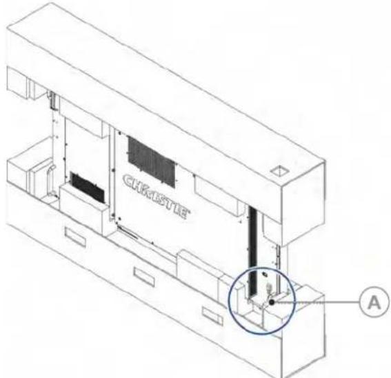
Inspecting the display panel
Conduct an inspection on the display panel and verify the panel functions as expected before unpacking.
If any damage is identified, or the panel does not function as expected, contact Christie Technical Support.
- Tear off the sticker for a small opening on the right bottom corner at the back of the display panel (A).
text_image
CHRISTIE A-
Pull the power cable through the packaging.
-
Connect the power cord to a power source and turn on the display panel.
For AC models, pull out the extended power cable and connect it to an AC power cord.
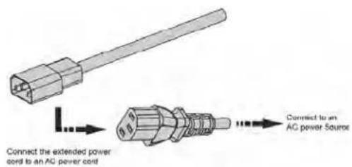
text_image
Connect the extended power cord to an AC power cord Connect to an AC power SourceFor DC models, pull out the DC power cord.

text_image
Christie DC Remote Power One of the Output ports Connect to a DC power sourceWhen connecting to a power source for the first time, the display panel automatically cycles through test patterns for 15 minutes (only).
- As the display panel is cycling through the test patterns, inspect the display.
Handling and mounting guidelines for extreme narrow bezel series panels
Follow these best practices when handling and mounting extreme narrow bezel panels.

Notice. If not avoided, the following could result in property damage.
- When moving the panel, always use the handles. Do not carry the panel by the frame.
- Do not twist, bend, or tilt the panel.
- Do not apply excessive force to the sides of the bezel when mounting the panel or pushing into its locked position.
- Always handle the display panel from the sides or handles.
Follow the following guidelines before removing the panel from the packaging.
• To verify normal operation before handling, power on the panel in the packaging.
• Always use the handles to pick up and carry the panel.
- Leave the panel in the box until the mount is on the wall and you are ready to install the panel.
- To avoid putting undue stress on the panel when mounted, make sure the mount is square, flat, and level.
- Do not rest panels on top of a lower panel.
- When inserting the panel into the wall, pay close attention to adjacent panels.
- Make sure there is a minimum of 0.5 mm between mounted panels to allow for thermal expansion.
Cleaning the panel
Learn how to clean the display panel.
After disconnecting the power cable, wipe contaminated parts and each part of the product screen lightly with a dry and soft cloth.
Do not use a liquid, spray cleaners, or any abrasive cleaners to clean the LCD panel.
Washing with various cleaning agents, brighteners, abrasives, waxes, benzene, alcohol, solvent, surface active agent, may damage the surface of the product.
Key features
Learn the key features of the display panel.
• Full-HD native resolution: 1920x1080 (16:9 native aspect ratio)
• High brightness: up to 500 nits
• 178-degree viewing angle
- DisplayPort 1.2, HDMI 1.4 and DVI inputs with High-bandwidth Digital Content Protection (HDCP)
- DisplayPort 1.2 output to support daisy-chaining UHD content (3840x2160) up to 16 display panels, regardless of which digital input connector is used first
• Video wall resolution up to 3840x2160 (UHD)
- Displays native 4K content at 60 Hz on a 2x2 video wall for sources that support Multi-Stream Transport (MST)

Multi-Stream Transport (MST) requires a video card that supports this feature and DisplayPort 1.2.
- Video signal looping
- Direct LED backlight
- Video Wall Toolbox 2.0 software simplifies the set up of a large video wall, with up to 100 displays, using a Windows PC
• Portrait and Landscape compatible - OPS slot
Related documentation
Additional information on the LCD panels is available in the following documents.
• FHD493-XE Product Safety Guide (P/N: 020-102681-XX)
• Extreme Series External Controls Technical Reference (P/N: 020-102499-XX)
Parts list
Your display panel is shipped with the following items. If any items are missing or damaged, contact your dealer.
- Remote control unit and batteries
- Power cord
- DisplayPort cable—1.8m
• RS485 communications cable—2m - Joint metal plate kit
- IR extender cable
- Spacer tool—Qty 2 (P/N: 003-006724-XX)
Important safeguards
To prevent personal injury and to protect the device from damage, read and follow these safety precautions.
General safety precautions
Observe these important safety rules to avoid personal injury or damage to the product.

Warning! If not avoided, the following could result in death or serious injury.
- A minimum of two people or appropriately rated lift equipment is required to safely lift, install, or move the product.
- Do not drop the product.
- Do not apply excessive force to the sides of the bezel when mounting the panel or pushing into its locked position.
- Always handle the product on the opposing corners of the bezel to avoid direct contact with the glass.
- TIP HAZARD! When shipping a panel, use the provided packing materials and secure to a pallet.
- When moving the panel, always use the handles. Do not carry the panel by the frame.

Caution! If not avoided, the following could result in minor or moderate injury.
- Do not tilt the product more than ± 15 degrees.
- Use the handles when moving the shipping package.
- Do not twist, bend, or tilt the panel.

Notice. If not avoided, the following could result in property damage.
- Only clean the components with Christie approved products.
AC power precautions
Learn the safety precautions related to AC power.

Caution! If not avoided, the following could result in minor or moderate injury.
- SHOCK HAZARD! Disconnect the product from AC before installing, moving, servicing, cleaning, removing components, or opening any enclosure.
Controls and functions
Learn about the various parts and functions of the LCD panel.
Display at a glance
Learn about the key display components.
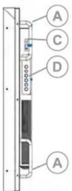
text_image
A C D A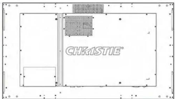
text_image
CHKISTIE®
text_image
A A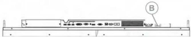
natural_image
Diagram of a computer monitor with labeled ports and indicator lights (no text or symbols beyond label B)| A | Handles—Always use the handles when carrying the display. Do not touch or hold the screen face or panel edges. |
| B Main power switch—Connects or disconnects the display panel from the power source. | |
| C | Status LED—Lights orange to indicate that the display is in standby mode; blinks orange if no input signal is present; off if the main power switch is set to Off. |
| D | Keypad—You can use the keypad instead of the remote control unit to operate the on-screen display (OSD) controls. The keypad operates as follows:On/Standby—Press once to toggle from Standby mode to On mode. Press it again to return to Standby mode.SOURCE—To select a source, press the SOURCE button repeatedly (with no menus visible on-screen).Right key—When a menu is visible on-screen, this button operates identically to the right-arrow (or ENTER) button on the display remote control unit. |
- Left key—When a menu is visible on-screen, this button operates identically to the left-arrow button on the display remote control unit.
- Up and down keys—When a menu is visible on-screen, these buttons operate identically to the up and down-arrow buttons on the display remote control unit.
- MENU/EXIT—Press this button to access the on-screen display (OSD) controls, or to exit the current menu and return to the previous one.
Input panel
Learn the components of the display input panel.

text_image
A B C E G I J L N O D F H K M| A Kensington Lock Slot—F or use with a Kensington lock (sold separately) for securing the display panel. | |
| B | OPS slot—An optional OPS slot for connecting an OPS module (sold separately) to display content. |
| C | DP In—DisplayPort 1.2 and HDCP-compliant digital video input for connecting DisplayPort sources. |
| D HDMI 1, 2—Two HDCP-compliant digital video inputs for connecting HDMI or DVI sources. | |
| E DVI-D—VESA-standard digital video input for connecting DVI sources. | |
| F | VGA—VESA-standard analog video input for connecting a personal computer or another analog video source. |
| G IR In—An IR receiver sensor that sends information from an infrared remote control to another device by receiving and decoding signals. | |
| H | DP Out—DisplayPort 1.2 and HDCP-compliant digital video output for connecting the display panel to the next display panel in a video wall. This output can be used with DP, HDMI or DVI inputs. For more information about creating a video wall, see Creating a video wall (on page 23). |
| I DP Out (OPS)—A DisplayPort 1.2 and HDCP-compliant digital video output for sharing content coming from an OPS module. | |
| J | Ethernet—An RJ-45 connector for connecting to a computer or a home theater system over a wired Ethernet network. |
| K | RS232 In—A female, 9-pin D-sub connector for interfacing with a PC or a home theater automation or control system. |
| L RS485 In—A female, 8-pin RJ-45 connector that connects to the next video source. For more information about creating a video wall, see Creating a video wall (on page 23). | |
| M | RS485 Out—A female, 8-pin RJ-45 connector that connects to the next display panel in a video wall. For more information about creating a video wall, see Creating a video wall (on page 23). |
| N Power Input (100 to 240 VAC)—Connect the display panel to power here. | |
| O Power Switch—Turn the display panel on or off. | |
Remote control unit
Learn the functions of the remote control.
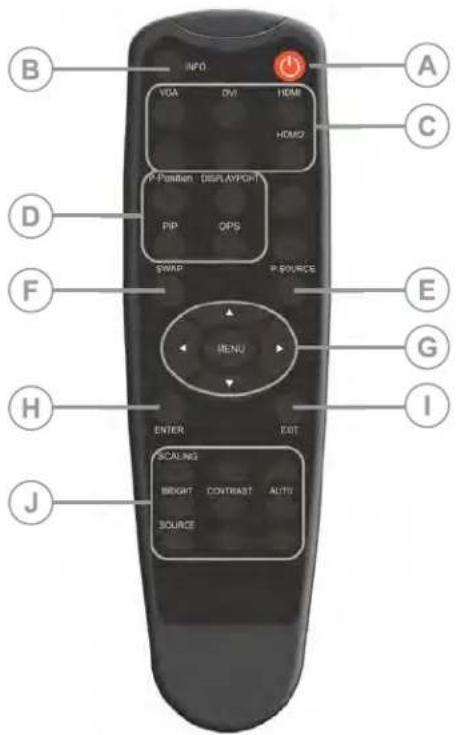
text_image
INFO VGA DVI HDMI HOMO2 P Position DISPLAY/PGT PIP QPS SWAP P SOURCE MENU E G I H ENTER EXIT SCALING BRIGHT CONTRAST ALTU SOURCE J B C D F| A Power— | Turns the display panel on or off. |
| B INFO— | Provides source and resolution information. |
| C Sources | VGA—Selects the VGA source.DVI—Selects the DVI source.HDMI 1—Selects the HDMI source 1.HDMI 2—Selects the HDMI source 2. |
| D Display options | P-Position—Selects the PIP position.DISPLAYPORT—Selects the DisplayPort source.PIP—Turns the PIP feature on or off.OPS—Selects the OPS source. |
| E P-Source— | Selects the secondary sub-source. |
| F Swap— | Swaps the main and PIP source. |
| G Navigation buttons | MENU—Opens the monitors on-screen menu system. If the menu is already open, pressing this button selects the previous submenu农药Arrow Keys—Navigate through submenus and settings. |
| H ENTER—Selects highlighted menu choices. | |
| I EXIT—Closes the menu system. | |
| J Image adjustments | |
Installing a display panel
Learn how to install and configure the display panel and the remote control.
Christie recommends that the ambient temperature around a display panel or a video wall remain constant and below 40 degrees Celsius (104 degrees Fahrenheit). Ensure the display panel or video wall is kept away from heating and air conditioning vents.
If you are mounting a display panel in an enclosure, ensure sufficient space is left on all sides between it and surrounding objects. Doing so allows heat to disperse, and helps to maintain the proper operating temperature. If you are mounting a display panel close to a wall, or are using an OPS module, active cooling may be required to remove heat and maintain an ideal ambient temperature.
For thin installations or to mount the display close to a wall, remove the handles after hanging the display on the extending wall mount by turning the handles counter-clockwise.
Inserting batteries in the remote control
Learn how to install batteries in the remote control.
Before you insert batteries in the remote control, consider the following:
- Ensure that the battery polarities are correct.
- Do not mix an old battery with a new one or mix different types of batteries together.
- Do not expose batteries to excessive heat such as sunlight or fire.
If you will not use the remote control for a long time, consider removing the batteries to avoid damage from battery leakage.
- On the back of the remote control, press down on the tab on the cover and pull the cover up.
- Insert the batteries. Ensure that the polarities correctly match the + and - markings inside the battery compartment.
- Insert the lower tab of the cover into the opening, and press down on the cover until it clicks in place.
Operating the remote control
Consider the following when using the remote control.
- Verify that nothing is obstructing the infrared beam between the remote control and the IR receiver on the display panel.
- If the effective range of the remote control decreases, or it stops working entirely, replace the existing batteries with new ones.
-
If necessary, use an IR extender to move the IR receiver to a more convenient place. For more information, see Creating an IR extender connection (on page 20).
-
If the infrared remote sensor is exposed to bright sunlight or fluorescent lighting, the remote control might become unresponsive.
- Ambient conditions might impede the operation of the remote control. If this occurs, point the remote control directly at the display panel and repeat the desired operation.
Locking or unlocking the remote control
Lock or unlock the remote control buttons to prevent unauthorized individuals from changing the display settings.
- On the remote control, press ENTER > ENTER > EXIT > EXIT > ENTER > EXIT to lock the remote control.
- To unlock the remote control, enter the same sequence of commands.
Mounting a display panel
Use only the approved wall-mount kit designed for your display panel.

Caution! If not avoided, the following could result in minor or moderate injury.
- TIP HAZARD! Center align the product on the stand or mount.
If you decide to wall-mount a display panel, ensure that the wall-mount bracket is installed according to the instructions that are included with it. The wall must be capable of supporting three times the weight of the display panel, or be reinforced.
To ensure the mounting brackets clear any protrusions on the rear of the panel, Christie recommends using spacers with a minimum height of 6.35 mm (.25 in).
Mounting brackets may block access to the connector ports. To ensure the preferred mount allows access to the connectors, refer to the display panel line drawings on www.christiedigital.com for measurements.
At the location where the space between tiles is the tightest, use the spacer tool to ensure there is a minimum of 0.5mm, or the thickness of a credit card, between adjacent LCD display panels.
Securing an LCD display panel to an adjacent panel
Learn how to install brackets securing two LCD display panels together.

After establishing the appropriate gap between tiles and aligning the tiles in the array, the brackets may no longer line up with the screw holes and cannot be used.
-
At the location where the space between tiles is the tightest, use the spacer tool to ensure there is a minimum of 0.5mm, or the thickness of a credit card, between adjacent LCD display panels.
Gaps smaller than 0.5mm may cause cracks in the glass. -
Align the tiles.
-
Install two of the #2 Phillips screws through the bracket into one of the panels.
-
Install the other two screws through the bracket into the adjacent panel.

natural_image
Close-up of a metallic door with four circular buttons and a black handle (no visible text or symbols)Connecting signal to the display panel
You can connect a display panel to video sources, external controllers, and power sources.
Follow these guidelines when you connect equipment to a display panel.
- Turn off all equipment before making any connections.
- Use the correct signal cables for each source.
- For best performance and to minimize cable clutter, use high-quality cables that are only as long as necessary to connect two devices. For example, avoid using a 20-foot cable if a 6-foot cable is sufficient.
- Ensure that the cables are securely connected. Tighten all thumbscrews on connectors that have them.
Connecting to an AC power source
Use the power cord that comes with the display panel to connect the panel to an external power source, such as an AC wall outlet.

natural_image
Technical illustration of a connector with a close-up view of the internal socket (no text or symbols)Connecting a display panel to a control system or a computer
Learn how to create an RS232, an Ethernet, or an IR extender connection.
Creating an RS232 connection
A straight-through RS232 cable with a 9-pin male connector is required.
- Connect the RS232 cable to the RS232 port on the display panel.
- Connect the RS232 cable to the control computer.
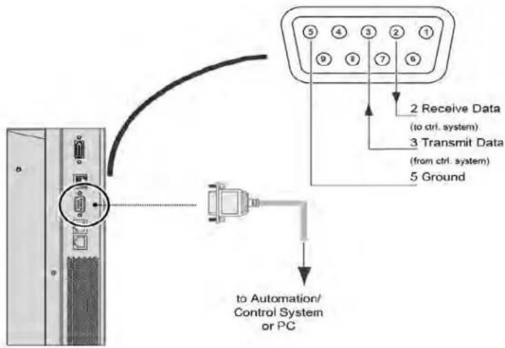
text_image
2 Receive Data (to ctrl. system) 3 Transmit Data (from ctrl. system) 5 Ground to Automation/ Control System or PCCreating an Ethernet connection
Use a standard Ethernet cable with an RJ45 male connector.
- Connect the Ethernet cable to the Ethernet port on the display panel.
- Connect the Ethernet cable to the control computer.

text_image
8 6 Receive Data - 3 Receive Data + 2 Transmit Data - 1 Transmit Data + to Ethernet Hub, Router or GatewayCreating an IR extender connection
Learn how to connect an IR extender cable to a display panel.
- Connect the IR extender cable to the IR extender input on the display panel.
- Place the extender cable receiver in a location that can be detected by the remote.
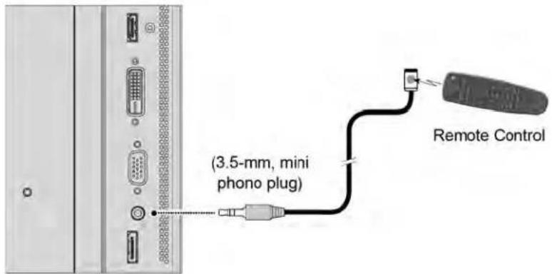
text_image
(3.5-mm, mini phono plug) Remote ControlConnecting source components to a display panel
Learn how to connect video sources to a display panel.
Connecting a DisplayPort source
Learn how to connect a control computer to a display panel using a DisplayPort source.
- Connect the DisplayPort cable to the DisplayPort in port on the display panel.
- Connect the DisplayPort cable to the control computer.

If you are using Multi-Stream Transport (MST), DisplayPort 1.2 input and output can support daisy-chaining up to four display panels.
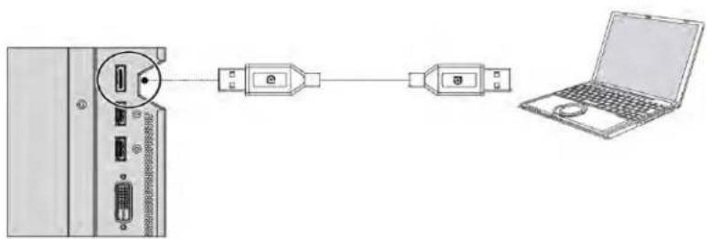
natural_image
Diagram showing connection between a server unit and two connected devices via a laptop (no text or symbols present)Connecting an HDMI or a DVI-D source
Learn how to create a connection using an HDMI or a DVI-D source.
-
Do one of the following.
-
Connect an HDMI or a DVI-to-HDMI cable to the HDMI port on the display panel.
-
Connect a DVI-D cable to the DVI-D port on the display panel.
-
Connect the cable to the control computer.

text_image
HDMI or DVI-to-HDMI Cable (sold separately) BD/HD-DVD/ DVD/DTV STB DVI-D Cable (sold separately) Rear of the PCConnecting a VGA source
Learn how to connect a control computer to a display panel using a VGA source. You cannot daisy-chain multiple panels together using a VGA source connection.
- Connect a VGA cable to the VGA port on the display panel.
- Connect the cable to the control computer.
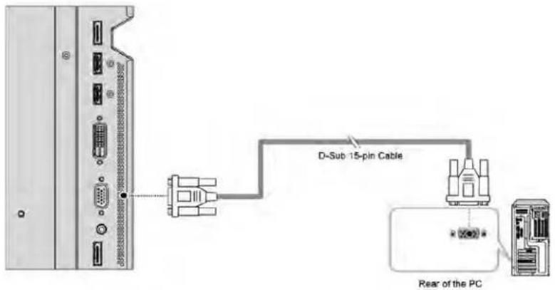
text_image
D-Sub 15-pin Cable Rear of the PCCreating a video wall
Learn how to set up an array of display panels in a video wall.
Connecting video by daisy-chaining display panels
If you are using Multi-Display Control commands, all display panels in a video wall should receive the same video signal.
You can do this using an external video splitter, or by daisy-chaining up to 16 display panels together using the DP Out connector.
If you are daisy-chaining the display panels together, consider the following:
- The DP Out connector on a display panel performs the same function as an external video splitter.
- The DP Out connector functions as a repeater for all digital inputs, including DVI In, HDMI 1 In, HDMI 2 In, and DP In.
- The DP Out connector does not support VGA In. If your source is VGA, you cannot daisy-chain display panels together.
- To daisy-chain display panels, connect a digital source to the first panel in the video wall. Subsequent display panels can be connected using the DisplayPort cable using the upstream DP Out and the downstream DP In connections.
- The maximum number of display panels that can be daisy-chained using the DP Out connector is 16.
- If more than 16 display panels are required, daisy-chaining can be used in combination with an external video splitter.
Ensure that the DP Out connector is not confused with the OPS DP Out connector. The DP Out connector is used for daisy-chaining display panels. The OPS DP Out connector is used to connect a second display panel to the installed OPS module (sold separately).
- To daisy-chain video throughout a video wall using a single video source, connect the DVI, HDMI or DisplayPort video source to the first display panel in the video wall.
- Connect the remaining display panels using the DP out of the upstream display panel and the DP In of the downstream display panel.
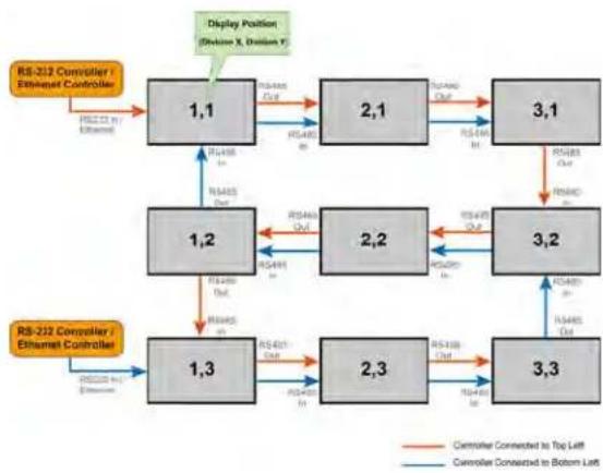
Connecting an RS232 or an Ethernet controller to a video wall in landscape orientation
Complete the following steps to connect an RS232 or an Ethernet controller to a video wall in landscape orientation.
It is not recommended that more than 25 display panels be daisy-chained together using the RS485 input and outputs. If you are working with a video wall that exceeds 25 display panels, consider breaking the video wall into groups of 25 display panels or less, and then use separate RS232 or Ethernet connections to control each group.
To control a video wall using the IR remote control, plug the IR extender into the first display panel in the daisy-chain.
- Connect the controller to the top-left or bottom-left display panel.
- Connect the remaining panels as illustrated.
flowchart
graph TD
    A["RS-212 Controller / Ethernet Controller"] -->|RS22 CI in Ethernet| B["1,1"]
    B -->|RS400 Out| C["1,2"]
    C -->|RS401 Out| D["1,3"]
    D -->|RS401 In| E["2,1"]
    E -->|RS400 Out| F["2,2"]
    F -->|RS400 In| G["3,1"]
    G -->|RS401 Out| H["3,2"]
    H -->|RS400 In| I["3,3"]
    I -->|RS401 Out| J["2,3"]
    J -->|RS400 In| K["1,3"]
    K -->|RS400 Out| L["1,2"]
    L -->|RS400 In| M["1,1"]
    M -->|RS400 Out| N["Display Position (Division X, Division Y)"]
    N --> O["RS-212 Controller / Ethernet Controller"]
    O -->|RS22 CI in Ethernet| P["1,1"]
    P -->|RS400 Out| Q["2,1"]
    Q -->|RS400 Out| R["3,1"]
    R -->|RS400 In| S["3,2"]
    S -->|RS401 Out| T["2,3"]
    T -->|RS400 In| U["1,3"]
    U -->|RS400 Out| V["1,2"]
    V -->|RS400 In| W["1,3"]
    W -->|RS401 Out| X["2,3"]
    X -->|RS400 In| Y["3,3"]
    Y -->|RS401 Out| Z["3,2"]
    Z -->|RS400 In| AA["1,3"]
    AA -->|RS400 Out| AB["1,2"]
    AB -->|RS400 In| AC["1,1"]
    AC -->|RS400 Out| AD["Display Position (Division X, Division Y)"]
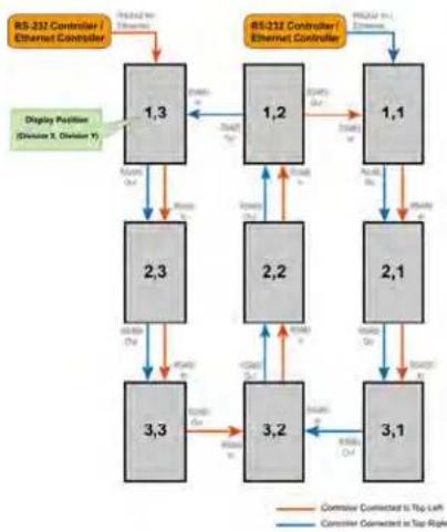
Connecting an RS232 or an Ethernet controller to a video wall in portrait orientation
Complete the following steps to connect an RS232 or an Ethernet controller to a video wall in portrait orientation.
It is not recommended that more than 25 display panels be daisy-chained together using the RS485 input and outputs. If you are working with a video wall that exceeds 25 display panels, consider breaking the array in to groups of 25 display panels or less, and then use separate RS232 or Ethernet connections to control each group.
When you create a video wall in portrait orientation, both the video source and the content must be configured for use in a 9:16 format.
- Connect the controller to the top-left or the top-right display panel.
- Connect the remaining panels as illustrated.
flowchart
graph TD
    A["RS-232 Controller / Ethernet Controller"] --> B["1,3"]
    A --> C["1,2"]
    A --> D["1,1"]
    B --> E["2,3"]
    B --> F["2,2"]
    C --> G["2,1"]
    C --> H["3,1"]
    D --> I["3,2"]
    D --> J["3,3"]
    E --> K["Display Position (Session X, Division Y)"]
    F --> L["Display Position (Session X, Division Y)"]
    G --> M["Display Position (Session X, Division Y)"]
    H --> N["Display Position (Session X, Division Y)"]
    I --> O["Display Position (Session X, Division Y)"]
    J --> P["Display Position (Session X, Division Y)"]
    K --> Q["Controller Connected to Top Left"]
    L --> R["Controller Connected to Top Right"]
    M --> S["Controller Connected to Top Left"]
    N --> T["Controller Connected to Top Right"]
    O --> U["Controller Connected to Top Left"]
    P --> V["Controller Connected to Top Right"]
Turning on the display panel
Learn how to turn the power on.
- Turn on all source components.
- Connect the power cord to the power receptacle on the side of the display panel.
- Connect the other end of the power cord to a power source.
-
On the side of the display panel, turn on the main power switch. When the display panel is in Standby mode, the power indicator turns orange.
-
To turn on the display panel, press the power button on the remote control or the keypad. It might take a few minutes for the display panel to warm up. Once it is warmed up, an image appears on the screen.
Avoiding image retention
Image retention can occur when static content appears on the display panel for long periods of time. Image retention is not covered under warranty. To prolong the life of your display panel, follow these recommendations.
- Operate the display panel within its rated ambient environment. Christie recommends an operating temperature of 5 to 40 degrees Celsius (41 to 104 degrees Fahrenheit), with a maximum relative humidity of 75% .
- Avoid static content. Christie recommends displaying moving images whenever possible, and using a screen saver with a moving image.
- Turn off the display panel when it is not in use, or use the Real Time Clock feature to automatically turn off the display panel at preset times of the day.
- Turn on the IRFM setting.
Configuring the on-screen display
Learn how to configure the on-screen display (OSD).
Setting the on-screen display transparency
Learn how to set the transparency of the on-screen display.
- Press MENU on the remote control or keypad.
- Select Basic Settings > OSD Transparent.
- Use the arrows to adjust the degree of translucence in the menus and message boxes. Zero (0) means that the menus are opaque.
Changing the location of the on-screen display
Learn how to change the location of the on-screen display.
- Press MENU on the remote control or keypad.
- Select Basic Settings > OSD Location.
- Use the arrows to move the OSD menu to the desired location.
Setting the size of the on-screen display
Set the on-screen display size.
- Press MENU on the remote control or keypad.
- Select Basic Settings > OSD Zoom.
- Use the arrows to display a normal sized or enlarged OSD menu.
Rotating the on-screen display
Learn how to rotate the on-screen display.
- Press MENU on the remote control or keypad.
- Select Basic Settings > OSD Rotation.
- Use the arrows to change the orientation of the OSD menu to match that of the display.
Changing the on-screen display language
By default, the on-screen display language is English.
You can change the display language to Simplified Chinese, French, German, Italian, Portuguese, Russian, Spanish, Korean, or Japanese.
- Press MENU on the remote control or keypad.
- Select Basic Settings > OSD Language.
- Select a language, and then press Enter.
The change takes effect immediately.
Configuring the on-screen display timeout
Learn how to configure the on-screen display timeout.
- Press MENU on the remote control or keypad.
- Select Basic Settings > OSD Timeout.
- Use the arrows to specify how long the menus remain on-screen after selecting them. Select from 5 to 120 seconds, in five-second increments.
Changing the behavior of the power LED
Learn how to change the behavior of the power LED.
- Press MENU on the remote control or keypad.
- Select Basic Settings > Power LED.
-
Use the arrows to change the behavior of the status indicator LED during standby mode.
-
On—The LED lights orange to indicate that the display is in standby mode.
- Off—The LED is always off, regardless of the operational state of the display.
Changing the date and time
Learn how to change the date and time on the display panel.
- Press MENU on the remote control or keypad.
- Select Basic Settings > Real Time Clock > Current Time.
- Use the arrows to change date and time.
Scheduling when the display is on
Set when the display panel turns on or turns off.
- Press MENU on the remote control or keypad.
-
Select Basic Settings > Real Time Clock > Timer Mode.
-
Use the arrows to program the display to turn on and off at specified times of day and days of the week.
-
User— Set power-on and power-off times for each day of the week independently.
- Same Settings on All—Set the same power-on and power-off times for every day of the week.
-
Same Settings on Work Days—Set the same power-on and power-off times for Monday through Friday.
-
Select Enable for each day the schedule is active.
Adjusting the image
Use the controls in the Image Settings Menu to calibrate each display input to achieve optimum picture quality.
Changing the image preset
Learn how to change the image preset.
-
Press MENU on the remote control or keypad.
-
Select Image Settings > Scheme.
-
Select one of four presets (Vivid, Cinema, Game or Sport) depending on the type of program material you are viewing.
These presets automatically adjust the other image settings for optimal image quality.
- Alternatively, select User to adjust Brightness, Contrast and other settings manually.
Modifying the brightness
Brightness and contrast controls are interactive.
A change to one may require a subtle change to the other in order to achieve the optimum setting.
- Display a PLUGE (Picture Line-Up Generation Equipment) test pattern.
PLUGE patterns vary but generally consist of some combination of black, white and gray areas against a black background. The example below includes two vertical bars and four shaded boxes.

text_image
Below Black Above Black-
Press MENU on the remote control or keypad.
-
Select Image Settings > Brightness.
-
Use the arrows to adjust the brightness until:
• The darkest black bars disappear into the background.
• The dark gray areas are barely visible.
• The lighter gray areas are clearly visible.
- The white areas are a comfortable level of true white.
• The image contains only black, gray and white (no color).
Changing the contrast
Brightness and contrast controls are interactive.
A change to one may require a subtle change to the other in order to achieve the optimum setting.
- Display a stepped, gray-bar test pattern.
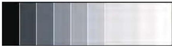
natural_image
Gradient grayscale image with vertical bands of varying shades from black to white (no text or symbols)-
Press MENU on the remote control or keypad.
-
Select Image Settings > Contrast.
-
Use the arrows to adjust the contrast to a point where the white rectangle starts to increase in size.
Sharpening the image
Learn how to sharpen the image on a display panel.
- Select a test pattern similar to the one shown below.

natural_image
Symmetrical abstract diagram with concentric circles and diagonal lines, no text or symbols present-
Press MENU on the remote control or keypad.
-
Select Image Settings > Sharpness.
-
Use the arrows to adjust the sharpness. Look for white edges around the transitions from black to gray and differently-sized lines in the sweep patterns at the top and bottom. Lower the sharpness setting to eliminate them.
Changing the saturation
Saturation and hue are interactive.
A change to one may require a subtle change to the other in order to achieve the optimum setting.
- Select a color bar test pattern similar to the one shown below, and apply a blue filter.
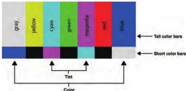
text_image
gray yellow cyan green magenta red blue Tall color bars Short color bars Tint Color-
Press MENU on the remote control or keypad.
-
Select Image Settings > Saturation.
-
While looking at the color bar pattern through a blue filter, adjust the color saturation level until the outermost (gray and blue) color bars appear to be a single shade of blue.

text_image
gray cyan magenta blue Tint Color ← Tall color bars ← Short color barsAdjusting the hue of the image
The hue (or tint) is the ratio of red to green in the color portion of the image.
When hue is decreased, the image appears red; when it is increased, the image appears green.
Saturation and hue are interactive. A change to one may require a subtle change to the other in order to achieve the optimum setting.
-
Select a color bar test pattern, and apply a blue filter.
-
Press MENU on the remote control or keypad.
-
Select Image Settings > Hue.
-
Use the arrows to adjust the hue until the cyan and magenta color bars (on either side of the green bar) appear to be a single shade of blue.
Changing the backlight
Learn how to change the backlight setting on a display panel.
- Press MENU on the remote control or keypad.
- Select Image Settings > Backlight.
- Use the arrows to adjust the apparent brightness of the image.
Changing the gamma settings
Learn how to change the gamma settings on a display panel.
- Press MENU on the remote control or keypad.
- Select Image Settings > Color Temperature & Gamma > Gamma.
- Use the arrows to select 2.2 (default) or Off.
When off is selected, Calibration, Color Temperature, Gain, and Offset settings are not available.
Calibrating the image
Learn how to calibrate the image on a display panel.
- Press MENU on the remote control or keypad.
- Select Image Settings > Color Temperature & Gamma > Calibration.
-
Select the display type.
-
Single Display—Use when a single display panel is used by itself, not as part of a video wall. In this mode, the display panel is calibrated to match the selected color temperature very closely.
- Multi-Display—Use when the display panel is used as part of a video wall. In this mode, the display panel is finely calibrated to match adjacent displays.
When display panels are used as part of a video wall, all display panels in the video wall should have Calibration set to Multi-Display for best panel matching.
Setting the color temperature
Learn how to set the color temperature on a display panel.
- Press MENU on the remote control or keypad.
- Select Image Settings > Color Temperature & Gamma.
- Use the arrows to adjust the overall color temperature, or to adjust the individual gain and offset for red, green, and blue.
Selecting the flesh tone
Learn how to update the flesh tone setting on a display panel.
- Press MENU on the remote control or keypad.
- Select Image Settings > Flesh Tone.
- Use the arrows to adjust the skin color without affecting the rest of the picture.
Turning off local dimming
By default, local dimming is set to On.
Local dimming automatically adjusts areas of the LCD backlight to create deeper black levels and higher contrast. To avoid an overly dark image when displaying content that includes fine details on a black background, turn this feature off.
- Press MENU on the remote control or keypad.
- Select Image Settings > Local Dimming.
- Select Off.
Updating display settings
Learn how to configure basic and advanced display settings.
Configuring the display settings
Complete these tasks when configuring the display.
Changing the aspect ratio
Some aspect ratios are unavailable or not useful with certain types of source material.
The optimal setting depends on a number of factors, such as:
- The aspect ratio of the source material, such as broadcast or encoded on the playback medium.
- The "display type" (16:9 or 4:3) and output resolution settings at the source component. Most modern DVD/BD players and set-top boxes have such controls.
- Viewer preference (original aspect ratio with "black bars," or a full-screen presentation with some distortion or cropping).
To change the aspect ratio, complete the following.
- Press MENU on the remote control or keypad.
- Select Display Settings > Aspect Ratio.
For the picture-in-picture settings, select Display Settings > PIP > Aspect Ratio
- Use the arrows to select the Full Screen (default), 4:3, Letterbox, or Native aspect ratio.
Setting the zoom level
Learn how to update the zoom level setting.
- Press MENU on the remote control or keypad.
- Select Display Settings > Zoom.
- Use the arrows to select the zoom level.
Enabling Auto Scan
Auto Scan causes the Main or PIP input select functions (using the SOURCE button on the remote control unit or keypad, or the P-Source button on the remote control unit) to skip over unused inputs, saving time.
-
Press MENU on the remote control or keypad.
-
Select Display Settings > Auto Scan.
For the picture-in-picture settings, select Display Settings > PIP > Auto Scan
- Use the arrows to select the enable and disable Auto Scan.
Selecting a source
Learn how to select a source.
- Press MENU on the remote control or keypad.
- Select Display Settings > Select Source.
- Use the arrows to select the source.
Source options include: VGA (default), HDMI1, HDMI2, DVI, DisplayPort, and OPS. The OPS option is only available if an OPS module is installed in the panel.
Enabling picture-in-picture mode
Learn how to turn on picture-in-picture mode.
- Press MENU on the remote control or keypad.
- Select Display Settings > PIP Mode.
- Use the arrows to enable picture-in-picture (PIP) mode and set the size of the PIP window.
To swap the main and PIP images, press SWAP on the remote control.
Selecting a picture-in-picture source
Learn how to select a PIP signal source.
- Press MENU on the remote control or keypad.
- Select Display Settings.
- Ensure PIP Mode is enabled.
- Select Select Source, and in the PIP Input Source table, use the arrow keys to select a source.
If a source cannot be used for PIP mode, a dash ( - ) appears for that source in the table.
Setting the picture-in-picture position
Learn how to set the picture-in-picture position.
- Press MENU on the remote control or keypad.
- Select Display Settings.
- Ensure PIP Mode is enabled.
- Select PIP > Position and use the arrows to select the position of the Picture-in-Picture window.
PIP position options include: Bottom Right, Top Left, Top Right or Bottom Left.
Choosing the side-by-side scale
Learn how to select the side-by-side scale.
-
Press MENU on the remote control or keypad.
-
Select Display Settings.
- Ensure PIP Mode is enabled.
- Select PIP > Side By Side Scale and use the arrows to select PIP, Main, Zoom In, or Zoom Out.
Configuring advanced settings
Learn how to configure advanced settings on a display panel.
Turning on auto adjustment
Auto adjustment forces the display panel to reacquire and to lock the input signal.
This can be useful if signal quality is marginal.
- Press MENU > Advanced Settings on the remote control or keypad.
- Select Auto Adjustment.
- Use the arrows to select Yes.
Correcting the image position (VGA sources)
Use the controls in the Image Position (VGA source) menu to fine-tune the image position.
- Press MENU on the remote control or keypad.
- Select Advanced Settings > Image Position.
-
Do one of the following.
-
Left/Right—To shift the image horizontally, press the arrow keys left or right.
- Up/Down—To shift the image vertically, press the arrow keys up or down.
Updating the clock (VGA sources)
The Clock control sets the frequency of the pixel sampling clock, indicated by the number of incoming pixels per line, so that all pixels generated by a particular source are sampled.
Steady flickering or several soft vertical stripes across the image can indicate poor pixel tracking. Proper pixel tracking helps to ensure that the image quality is consistent across the screen, that the aspect ratio is maintained and that the pixel phase can be optimized.
- Press MENU on the remote control or keypad.
- Select Advanced Settings > Clock.
- Adjust the slidebar until the image stabilizes.
Adjusting the phase (VGA sources)
Christie recommends that you adjust the phase after you adjust the clock.
The Phase control adjusts the phase of the pixel sampling clock relative to the incoming signal. Adjust the phase when an image continues to show shimmer or noise after the Clock settings are optimized.
For best results, use a test pattern that is smooth gray with a clear pattern of black and white pixels, or a similar "half on, half off" graphic image.
- Press MENU on the remote control or keypad.
- Select Advanced Settings > Phase.
- Adjust the slider until the image stabilizes and each pixel is clearly defined.
Changing VGA ADC settings
VGA ADC settings calibrate the analog-to-digital converter (ADC) for VGA sources on a display panel.
- Press MENU on the remote control or keypad.
- Select Advanced Settings > VGA ADC Settings.
- Adjust the settings.
Enabling IRFM
The Image Retention Frame Motion (IRFM) setting creates slight frame motion to help avoid image retention.
- Press MENU on the remote control or keypad.
- Select Advanced Settings > IRFM.
- Use the arrows to enable this feature.
Setting the baud rate
The baud rate sets the data rate of the RS232 communication link.
- Press MENU on the remote control or keypad.
- Select Advanced Settings > Baud Rate.
- Use the arrows to select a baud rate.
Choosing a Wake Up From Sleep mode
Choose when a display panel wakes up from power-saving mode.
- Press MENU on the remote control or keypad.
- Select Advanced Settings > Wake Up From Sleep.
-
Use the arrow keys to select one of the following.
-
VGA Only—The display panel wakes up from power-saving mode when it receives an active video signal on its VGA (analog) input.
- VGA, Digital, RS232—The display panel wakes up from power-saving mode when it receives an active signal from its VGA, HDMI, DisplayPort or DVI inputs, or when it receives a valid RS232 command.
- Never Sleep—The display panel never enters power-saving mode.
Configuring Ethernet settings
Learn how to configure network settings.
- Press MENU on the remote control or keypad.
- Select Advanced Settings > Ethernet Setup.
-
Use the arrows to update any of the following.
-
Enable Network—Select Yes to enable the network feature.
- Dynamic IP—Select Enable to enable DHCP for dynamic IP address assignment.
- Static IP Address—Sets the static IP address when the Dynamic IP is disabled, or views the static IP address when the Dynamic IP is enabled.
Range: 255.255.255.255 (0.0.0.0)
- Subnet Mask—Sets the subnet mask when the Dynamic IP is disabled, or views the subnet mask when the Dynamic IP is enabled.
Range: 255.255.255.255 (0.0.0.0)
- Gateway—Sets the gateway when the Dynamic IP is disabled, or views the gateway when the Dynamic IP is enabled.
Range: 255.255.255.255 (0.0.0.0)
- DNS Address—Sets the DNS address when the Dynamic IP is disabled, or views the DNS address when the Dynamic IP is enabled.
Range: 255.255.255.255 (0.0.0.0)
- Save Network Settings—If the Dynamic IP is disabled, select Yes to save the network configuration.
-
Email Alert—Enable or disable any of the following email alerts.
-
Power Status—Send an alert if a display panel is turned on or off.
- Source Status—Send an alert if a different source is selected.
- Signal Lost—Send an alert if the input signal is lost.
- Load Default Settings—Loads default network settings.
- Refresh—Refreshes the configuration of the Static IP Address, Subnet Mask, Gateway, and DNS Address.
- Device MAC—Shows the unique address assigned to network interfaces.
Updating Multi-Display Control settings
Use the Multi-Display Control to display content from a single video source over an entire video wall.
The content is automatically scaled and cropped in each display panel to create a single large virtual display spanning the full video wall. The Multi-Display Control also allows you to control other features, such as the removal of the geometric effect of the LCD bezels.
Before using the Multi-Display Control, consider the following.
- The largest video wall size supported by the Multi-Display Control is 10x10 (or 100 display panels). If a video wall exceeds this size, use an external video wall controller.
- If you are using VGA or DVI inputs, the maximum resolution of the video wall is 1920x1080 at 60 Hz.
- If you are using the HDMI or DisplayPort inputs, the maximum resolution of the video wall is 3840 x 2160 at 30 Hz, or 2560 x 1600 at 60 Hz.
When you use the Multi-Display Control, the identical video signal must be distributed to each display panel in a video wall. To do this, daisy-chain the display panels together using the video input and output connectors, or use an external video splitter.
- Press MENU on the remote control or keypad.
- Select Advanced Settings > Multi-Display Control.
-
Use the arrow keys to select any of the following controls.
-
Monitor ID—Manually set the Monitor ID of each display panel in a video wall.
- Video Wall—Enable or disable Video Wall mode. When enabled, each display panel in a video wall attempts to match its luminance settings with the adjacent panels it is connected to.
- Power On Delay—Stagger the Power-On sequence so that monitors do not turn on at once, reducing current requirements. Select a value from 0 to 30 seconds for each monitor.
Updating Multi-Display Control settings for a video wall
If you enable the Video Wall setting from the Multi-Display Control settings menu, additional settings are available.
- Press MENU on the remote control or keypad.
- Select Advanced Settings > Multi-Display Control.
- Use the arrows to turn on the Video Wall setting.
- Update any of the following settings.
- Video Delay—If you are displaying fast-moving video, this feature can eliminate tearing artifacts between adjacent rows of display panels in a video wall.
- Default—The default delay time for the display panel is set to Zero.
- Auto—Automatically sets the delay time of a display panel to eliminate tearing between rows in a video wall that is displaying fast-moving video.
- +1 Frame—If a video wall is two or three rows high, to eliminate tearing between the bottom row and the row above, set the bottom row to +1 Frame.
- -1 Frame—If a video wall is two or three rows high, to eliminate tearing between the top row and the row below, set the top row to -1 Frame.
- Frame—Enables or disables frame compensation to join the edges of adjacent display panels in a video wall together. This can compensate for the gap between the display panels.
When enabled, moving objects in a video move behind the gap. This allows for better continuity of motion across the video wall and is suitable for moving images. When disabled, joints between the display panels are shown. This is suitable for still images.
- Matrix X—Specifies the number of columns in a video wall.
- Matrix Y—Specifies the number of rows in a video wall.
- Division X—Specifies the horizontal position (column) of a display panel in a video wall.
-
Division Y—Specifies the vertical position (row) of a display panel in a video wall.
-
IR Mode— If the remote control should control all display panels in a video wall, select All. If the remote control should control one display panel at a time, select Target. To use this option, RS485 cables must be connected to the display panel.
- Recipient ID—Selects which display panel is controlled by the remote control. To use this feature, set the IR Mode to Target. RS485 cables must be connected to the display panel.
- Auto Video Wall Setup—Automatically sets the monitor IDs for all display panels in a video wall. To use this option, RS485 cables must be connected to the display panel.
Updating Anti-tearing settings
If displaying fast-moving video, the Anti-tearing feature can eliminate tearing artifacts between adjacent rows of display panels in an array.
When enabling or disabling the Anti-tearing feature, or if changing the Anti-tearing settings, you must power cycle the display panels in the array for the changes to take effect.
After the power cycle is complete, to achieve color matching in the array, you must readjust some image settings on the display panels. To learn how to adjust image settings, see the user manual.
- On the remote control or keypad, press MENU.
- Select Advanced Settings > Multi-Display Control.
- Use the arrows to turn on the Video Wall setting.
-
Select any of the following options.
-
Off—Produces good results for most content.
- Auto—Automatically adjusts LCD scanning to eliminate tearing between rows in an array displaying fast-moving video.
- Odd—Manually selects the best scan behavior for the odd rows of display panels in an array, for example, rows 1, 3, or 5.
-
Even—Manually selects the best scan behavior for the even rows of display panels in an array, for example, rows 2, 4, or 6.
-
Turn off the display panels in the array, and wait at least five seconds.
-
For changes to take effect, after at least 5 seconds, turn on the display panels in the array.
Obtaining the temperature and fan status
Learn how to obtain information about the health of a display panel such as the internal operating temperature, the cooling fan speed, or the highest temperature reached.
- Press MENU on the remote control or keypad.
- Select Advanced Settings > Temperature & Fan Status.
Enabling DisplayPort Multi-Stream Transport (MST)
When you enable DisplayPort MST, display panels in a video wall that are connected using DisplayPort 1.2 are recognized by the control computer as independent display panels instead of a single display.
Before enabling DisplayPort MST, consider the following.
- The Video Wall setting in the Multi-Display Control menu should be set to Off.
-
The graphics adapter and operating system on the control computer must support MST.
-
MST mode requires high-quality cables that are DisplayPort certified.
• Depending on the graphics adapter, up to 4 display panels can be daisy-chained in MST mode. -
In MST mode, the recommended resolution setting for each display panel is 1920x1080. The maximum resolution of a 2x2 video wall is 3840x2160 at 60 Hz.
-
Press MENU on the remote control or keypad.
- Select Advanced Settings > DisplayPort MST.
- Use the arrows to enable DisplayPort MST.
Disabling the OPS Always Powered setting
Learn how to turn off the OPS Always Powered setting.
- Press MENU on the remote control or keypad.
- Select Advanced Settings > OPS Always Powered > No.
Performing a factory reset
Learn how to restore all display settings, including image settings, to their factory defaults.
This action is not reversible.
- Press MENU on the remote control or keypad.
- Select Advanced Settings > Factory Reset.
- Use the arrow keys to select Yes.
Reading the system status
You can find the system status on the main menu of the display panel.
- Press MENU on the remote control or keypad.
- Select System Status.
The System Status menu is read-only and provides the following information about the display panel.
- The resolution and refresh rate of both main and picture-in-picture sources.
- The number of hours the display has been in operation.
- The current firmware version.
Recommended low-light image settings
If a display panel is set up in an area with low ambient light levels, such as a broadcast studio or a museum, the display panel should be set to a low luminance to blend in with the environment or to match the color temperature of studio lighting.
To attain the highest quality image, Christie recommends the following image settings for low-light environments.
| Image setting Recommended range | |
| Backlight 25% or higher | |
| Contrast 40% or higher | |
| Color Temperature 5000K or higher |
Troubleshooting
Learn about common issues and their solutions.
The FHD493-XE display panels do not require any routine maintenance. There are no user-serviceable or replaceable parts. Do not attempt to repair or replace any system component yourself unless you are a qualified, factory trained-technician, as doing so voids the product warranty.
The display does not turn on
No video is displayed on the panel.
Details
Possible causes for this issue include:
- The display is not plugged in or the power outlet is not active.
- The main power switch is off.
- The remote control batteries have run out.
Resolution
- Ensure that the display is plugged in and that the power outlet is active.
- Set the main power switch to the on position.
- Replace the batteries.
No picture appears on the display
The display is on and the menus appear, but there is no picture on the panel.
Details
Possible causes for this issue include:
- Incorrect source selection.
- Source component is not turned on.
- Source component is connected incorrectly or not at all.
Resolution
- Select the correct source.
- Turn on the source component.
- Check connections from the source component to the display.
The remote control does not work
Pressing buttons on the remote control does not affect the display.
Details
Possible causes for this issue include:
- The remote control batteries have run out.
- The buttons are locked.
- IR extender is not connected.
Resolution
- Replace the batteries.
- Unlock the buttons by pressing ENTER, ENTER, EXIT, EXIT, ENTER and EXIT, in sequence.
- Verify that the IR extender cable is correctly connected.
The image geometry is incorrect
The image is displayed with an incorrect aspect ratio.
Resolution
Select a different aspect ratio.
The content is jittery or unstable
The content on the display panel is poor-quality or the panel is improperly connected to the source.
In some cases, the horizontal or vertical scan frequency of the input signal may be out of range for the display panel.
Resolution
- Verify that the source is properly connected.
- Correct the quality of the content.
The image is too bright or lacks definition
The image contrast is set too high and the bright areas of the image have no definition.
Resolution
Decrease the contrast setting.
The image appears washed out
The dark areas of the displayed image are too bright.
Resolution
Decrease the brightness settings.
The image is too dark
The image appears too dark when the brightness or backlight are set too low.
Resolution
Increase the brightness or backlight settings.
Images from the HDMI source do not display
Source video over HDMI does not display on the panel.
Details
Possible causes for this issue include:
- The resolution and frequency of the video card in the computer are not compatible with the display.
- HDMI cable from source to display is either defective or too long.
Resolution
- Select a compatible resolution and vertical frequency.
- Try a known-good and/or shorter HDMI cable.
Computer images do not display correctly
Images that originate from a computer source do not display correctly on the panel.
Details
Possible causes for this issue include:
- The resolution and frequency of the video card in the computer are not compatible with the display.
- Clock and Phase settings need adjustment.
Resolution
- Select a compatible resolution and vertical frequency.
- Adjust Clock and Phase settings.
Specifications
Learn about the product specifications. Due to continuing research, specifications are subject to change without notice.
Physical specifications
Learn the physical specifications for the FHD493-XE panel.
| DescriptionDetails | |
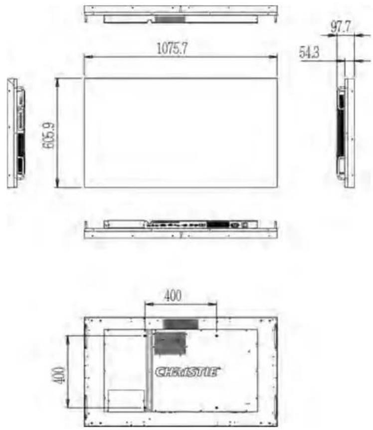
| Dimensions (W x H x D) 1075.7mm x 605.9mm x 97.7mm | |
| Weight Net: 25.7kg (w/o stand) / | 56.66lbs; Gross: 34.3kg / 75.62lbs |
| Wall mount 400mm x 400mm VESA | |
| Bezel width 0.9mm (top/left); 0.9mm (bottom/right) | |
| Image to image 2.3mm (typical) | |
| Brightness 500 cd/m2 | |
| Contrast ratio 1300:1 typical | |
| Viewing angle H: 178° / V: 178° | |
| Response time 8 ms typical | |
| Supported colors 1.07 billion | |
| Display resolution 1920 x 1080 (16:9) | |
| Display frame rate 60 Hz | |
| Rotation Landscape / Portrait | |
| Control RS232C, Ethernet, built-in | keypad, IR remote control |
| OSD Language | English, Simplified Chinese, French, German, Italian, Portuguese, Russian, Spanish, Korean, Japanese |
| Picture options | PIP, PBP (side-by-side) |
| Source auto detect | Yes |
| Key lock Yes | |
| Horizontal / Vertical frequency | 31 - 91 KHz / 56 - 85 Hz |
| Input resolution | 1920 x 1080 @ 60 Hz (Analog); 1920 x 1080 @ 60 Hz (Digital) |
| Connectors | DisplayPort (In/Out) / HDMI x 2 / DVI-D In / VGA In / IR Receiver / Ethernet / OPS DisplayPort Out / OPS slot |
| Communication ports | RS232C In, RS485 (In/Out) |
Power requirements
Learn the power requirements for the FHD493-XE panel.
Power consumption specifications do not include the power consumption of a control computer or a device connected to the OPS module of the display panel.
| Description Details | |
| Power supply AC 100V - 240V (50/60 Hz), 2.0 | Amps, maximum |
| Power consumption (normal operation) 105W | (typical), 140W (maximum, non-OPS) |
| Power consumption (standby mode) 0.5W | |
Environmental specifications
Learn the environmental specifications for the FHD493-XE panel.
| Description Details | |
| Operating temperature 5°C - 35°C, 90% RH | |
| Storage temperature -20°C - 60°C, 75% RH | |
| Heat output 654 BTU/hr (typical), | 806 BTU/hr (maximum, non-OPS) |
Supported timings
Learn the supported timings for FHD493-XE panels.
o = Compliant timing. ■ = Compliant timing for a video wall.
| Timing FH (kHz) FV (Hz) Dot clock | HDMI VGA DVI DisplayPort | ||||||
| (MHz) | |||||||
| VGA 640x480 | 31.469 | 59.94 | 25.175 | ○ | ○ | ○ | ○ |
| 37.861 | 72.809 | 31.5 | ○ | ○ | ○ | ○ | |
| 37.5 | 75 | 31.5 | ○ | ○ | ○ | ○ | |
| 43.269 | 85.008 | 36 | ○ | ○ | ○ | ○ | |
| SVGA 800x600 | 35.156 | 56.25 | 36 | ○ | ○ | ○ | ○ |
| 37.879 | 60.317 | 40 | ○■ | ○ | ○■ | ○■ | |
| 48.077 | 72.188 | 50 | ○ | ○ | ○ | ○ | |
| 46.875 | 75 | 49.5 | ○ | ○ | ○ | ○ | |
| 53.674 | 85.06 | 56.25 | ○ | ○ | ○ | ○ | |
| XGA 1024x768 | 48.363 | 60.004 | 65 | ○■ | ○ | ○■ | ○■ |
| 56.476 | 70.069 | 75 | ○ | ○ | ○ | ○ | |
| 60.023 | 75.029 | 78.75 | ○ | ○ | ○ | ○ | |
| Timing FH (kHz) FV (Hz) Dot clock (MHz) | HDMI VGA DVI DisplayPort | ||||||
| 68.677 84.997 | 94.5 | ○○○○ | |||||
| WXGA1360x768 | 47.712 60.015 | 85.5 | ○■○○■○■ | ||||
| VESA1280x720 | 44.444 59.98 | 64 | ○■○○■○■ | ||||
| 44.772 59.86 | 74.5 | ○■○○■○■ | |||||
| 56.456 74.78 | 95.75 | ○○○○ | |||||
| VESA1280x768 | 47.776 59.87 | 79.5 | ○■○○■○■ | ||||
| 47.396 59.995 | 68.25 | ○■○○■○■ | |||||
| 68.633 84.837 | 117.5 | ○○○○ | |||||
| VESA1280x800 | 49.306 59.91 | 71 | ○■○○■○■ | ||||
| 49.702 59.81 | 83 | ○■○○■○■ | |||||
| SXGA1152x864 | 67.5 75 108 | ○○○○ | |||||
| SXGA1280x1024 | 63.981 60.02 | 108 | ○○○○ | ||||
| 79.976 75.025 | 135 | ○○○○ | |||||
| 91.146 85.024 | 157.5 | ○○○○ | |||||
| 1440x900 55.469 | 59.901 88.75 | ○○○○ | |||||
| 55.935 59.88 | 106.5 | ○○○○ | |||||
| WSXGA+ 1680x1050 | 64.674 59.883 | 119 | ○■○○■○■ | ||||
| 65.29 59.954 | 146.25 | ○■○○■○■ | |||||
| VESA UXGA1600x1200 | 75 60 162 | ○○○○ | |||||
| VESA1920x1080 | 66.587 59.93 | 138.5 | ○■○○■○■ | ||||
| VESA WUXA1920x1200 | 74.038 59.95 | 154 | ○○○○■ | ||||
| EDTV 480p 31.5 | 60 27.03 | ○- | ○○ | ||||
| EDTV 576p 31.25 | 50 27 | ○- | ○○ | ||||
| HDTV 720p1280x720 | 37.5 50 74.25 | ○- | ○○ | ||||
| 44.995 59.94 | 74.176 | ○■- | ○■○■ | ||||
| 45 60 74.25 | ○■- | ○■○■ | |||||
| HDTV 1080p1920x1080 | 27 24 74.25 | ○- | ○○ | ||||
| 56.25 50 148.5 | ○■- | ○■○■ | |||||
| 67.433 59.94 | 148.352 | ○■- | ○■○■ | ||||
| 67.5 60 148.5 | ○■○○■○■ | ||||||
| 4K2K3840x2160 | 54 24 297 ○■○■ | ||||||
| 56.25 25 297 ○■○■ | |||||||
| 67.5 30 297 ○■○■ | |||||||
Overall dimensions
All dimensions are in millimeters.
Regulatory
This product conforms to the latest regulations and standards related to product safety, environmental, and electromagnetic compatibility (EMC) requirements.
Safety
- IEC 60950-1 IEC/EN 60950-1 – Information Technology Equipment – Safety – Part 1: General Requirements
Electro-magnetic compatibility
Emissions
- FCC CFR47, Part 15, Subpart B, Class A – Unintentional Radiators
• ICES-003 Issue 6:2016 Class A
• CISPR 32/EN 55032, Class A - IEC 61000-3-2/EN61000-3-2: Limits for Harmonic Current Emissions
- IEC 61000-3-3/EN61000-3-3: Limitations of Voltage Changes, Voltage Fluctuations, and Flicker
Immunity
• IEC 61000-3-3/EN61000-3-3
- IEC/EN61000
• IEC 61000-4-2/EN61000-4-2
• IEC 61000-4-3/EN61000-4-3
• IEC 61000-4-4/EN61000-4-4
• IEC 61000-4-5/EN61000-4-5
• IEC 61000-4-6/EN61000-4-6
• IEC 61000-4-11/EN61000-4-11
Environmental
EU Directive (2011/65/EU) on the restriction of the uses of certain hazardous substances (RoHS) in electrical and electronic equipment and the applicable official amendment(s).
EU Regulation (EC) No. 1907/2006 on the registration, evaluation, authorization and restriction of chemicals (REACH) and the applicable official amendment(s).
EU Directive (2012/19/EU) on waste and electrical and electronic equipment (WEEE) and the applicable official amendment(s).
China Ministry of Information Industry (along with 7 other Government Agencies) Order No.32 (01/2016) on the control of pollution caused by electronic information products, hazardous substances concentration limits (GB/T 26572 - 2011), and the applicable product marking requirement (SJ/T 11364 - 2014).
Corporate offices
| Christie Digital Systems USA, Inc.Cypressph: 714 236 8610 |
| Christie Digital Systems Canada Inc.Kitchenerph: 519 744 8005 |
Worldwide offices
| Australiaph: +61 (0) 7 3624 4888 | Germanyph: +49 2161 664540 | Republic of South Africaph: +27 (0)11 510 0094 | United Kingdomph: +44 (0) 118 977 8000 |
| Brazilph: +55 (11) 2548 4753 | Indiaph: +91 (080) 6708 9999 | Russian Federationand Eastern Europeph: +36 (0) 1 47 48 100 | United States (Arizona)ph: 602 943 5700 |
| China (Beijing)ph: +86 10 6561 0240 | Japan (Tokyo)ph: 81 3 3599 7481 | Singaporeph: +65 6877 8737 | United States (New York)ph: 646 779 2014 |
| China (Shanghai)ph: +86 21 6278 7708 | Korea (Seoul)ph: +82 2 702 1601 | Spainph: +34 91 633 9990 | Independent salesconsultant offi ces |
| Franceph: +33 (0) 1 41 21 44 04 | Mexicoph: +52 55 4744 1790 | United Arab Emiratesph: +971 4 3206688 | Italyph: +39 (0) 2 9902 1161 |