NTV-KIT457 - Dash cam NAV-TV - Free user manual and instructions
Find the device manual for free NTV-KIT457 NAV-TV in PDF.

User questions about NTV-KIT457 NAV-TV
0 question about this device. Answer the ones you know or ask your own.
Ask a new question about this device
Download the instructions for your Dash cam in PDF format for free! Find your manual NTV-KIT457 - NAV-TV and take your electronic device back in hand. On this page are published all the documents necessary for the use of your device. NTV-KIT457 by NAV-TV.
USER MANUAL NTV-KIT457 NAV-TV
natural_image
Interior view of a modern vehicle dashboard with steering wheel, speedometer, and infotainment screens (no visible text or symbols)Overview
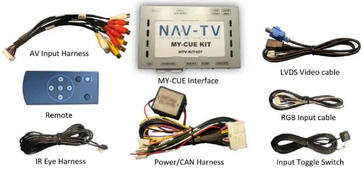
The MY-CUE Kit allows the user to add up to 3 audio/video inputs and a backup camera input to the factory media screen in select GM vehicles equipped with either the MYLINK or CUE media systems. This kit has a dedicated rear view camera input, 3 composite (RCA) audio/video inputs, an RGB input and an AV output with AV switching. Audio integration requires that the vehicle have a factory audio input.
Kit Contents
Agreement: End user agrees to use this product in compliance with all State and Federal laws. NAV-TV Corp. would not be held liable for misuse of its product. If you do not agree, please discontinue use immediately and return product to place of purchase. This product is intended for off-road use and passenger entertainment only.
BHM
12/3/13
NTV-DOC150
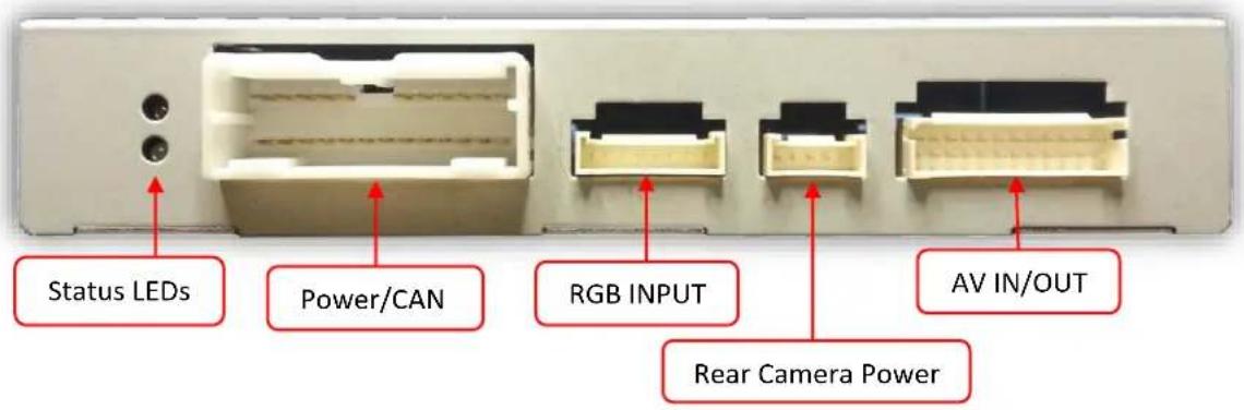
Interface Connectors
text_image
Status LEDs Power/CAN RGB INPUT AV IN/OUT Rear Camera Power
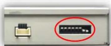
text_image
LCD IN/OUT (LVDS Cable) Dip SwitchesDip Switch Settings* Configure prior to installation
| Dip SW: | 1 | 2 | 3 | 4 | 5 | 6 | 7 | 8 |
| UP | EnablesRGB | EnablesV1 | EnablesV2 | EnablesV3 | N/ALeave up | N/ALeave up | Factory or no Rev-Cam | N/A |
| DOWN | SkipsRGB | SkipsV1 | SkipsV2 | SkipsV3 | N/A | N/A | Activates aftermarketRev-Cam | N/ALeave down |
natural_image
Close-up of a device panel with a highlighted black rectangle and a small connector (no visible text or symbols)*Note: If the dip switches are not configured prior to installation you must remove power to the unit prior to making adjustments to the dip switches. When power is reconnected after the dip switch adjustment the new settings will be stored into memory.
Agreement: End user agrees to use this product in compliance with all State and Federal laws. NAV-TV Corp. would not be held liable for misuse of its product. If you do not agree, please discontinue use immediately and return product to place of purchase. This product is intended for off-road use and passenger entertainment only.
Installation for GM trucks and notes for all other vehicles
THIS INTERFACE INSTALLS AT THE HMI MODULE, NOT AT THE SCREEN! THE HMI MODULE IS A BLACK PLASTIC BOX SHOWN IN STEP 3 OF THE NEXT PAGE.
| Vehicle | HMI Location |
| Cadillac ATS/CTS | Directly Below glove compartment |
| Cadillac SRX | Below/behind glove compartment |
| Corvette | Driver's kick |
| GM Truck | Behind glove compartment |
This chart will be updated as information is provided.
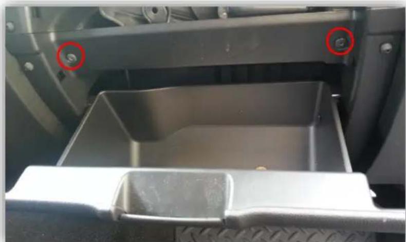
- GM trucks only: Remove the glove box, the HMI module is located behind it (black box with connectors). Remove (2x) Torx t15 screws:
natural_image
Interior view of a vehicle's trunk and side panel showing a plastic tray with a red circle highlighting a bolt (no text or symbols visible)- GM trucks only: Underneath the glove box you'll find (2x) more additional Torx T15 screws firing upwards. Remove these and pull the glove box free from the dash (all that remain are clips).
Agreement: End user agrees to use this product in compliance with all State and Federal laws. NAV-TV Corp. would not be held liable for misuse of its product. If you do not agree, please discontinue use immediately and return product to place of purchase. This product is intended for off-road use and passenger entertainment only.
- Remove the blue mini-USB connector shown here, and replace it with the blue male end of the provided LVDS cable. Make sure the connector is seated properly.

natural_image
Coiled black cable with blue and gold connectors, no visible text or symbols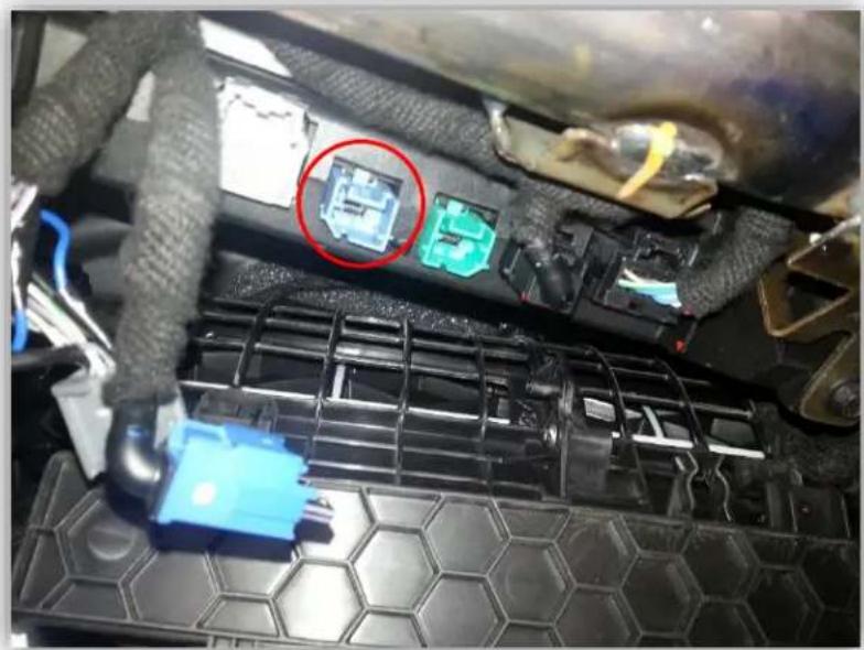
natural_image
Close-up of a car engine battery pack with a highlighted component (no visible text or symbols)- Plug the factory blue mini-USB connector into the black, female end of the provided LVDS cable.

natural_image
Coiled black cable with connectors, no visible text or symbols-
Connect the white plug from the provided LVDS cable into the port on the MY-CUE interface labeled 'LVDS IN/OUT'.
-
Connect the AV Input cable to the port on the MY-CUE interface labeled 'AV IN/OUT'. If
you're only connecting a reverse camera (and no other inputs), the signal input from the camera must connect
to the RCA labeled 'REAR-C'. Refer to the dip-switch settings chart to skip/enable AV sources upon toggle switch presses (optional. Page 2).

natural_image
Close-up of a black cable with multiple colored connectors (red, yellow, white) attached to its ends, no visible text or symbols.a. The provided R-CAM output provides power (red) and ground (black) for the
aftermarket rear view camera.
b. If you're installing a Nav-TV CAM 6 or Handle Cam, the power connector plugs directly into the MY-CUE interface port labeled 'R-CAM'.
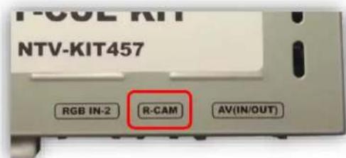
text_image
NTV-KIT457 RGB IN-2 R-CAM AV(IN/OUT)Agreement: End user agrees to use this product in compliance with all State and Federal laws. NAV-TV Corp. would not be held liable for misuse of its product. If you do not agree, please discontinue use immediately and return product to place of purchase. This product is intended for off-road use and passenger entertainment only.
- Optional: Connect the remote eye to the port labeled 'IR' (on the power harness) and leave it in clear view of the driver (often it can be stuck inside a vent). This connection would be necessary if you want to be able to adjust anything from the MY-CUE interface's menu.
a. While in any AV mode other than factory (on the display screen), press the MENU button for Menu 1, or hold the left arrow to enter MENU 2.
b. To switch between AV modes, press the 'OK' button.

text_image
POWER OK- Optional: Connect the provided momentary toggle switch to the
port on the MY-CUE interface labeled 'MODE'. Pressing this switch with the ignition on will cycle the screen modes as follows: factory screen > NAVI (RGB) > AV1 > AV2 > AV3
factory screen. Please refer to the dipswitch section on page 2 for input settings.

-
Connect the MY-CUE Power harness to the interface at the port labeled 'POWER/CAN'. Connect the RED wire to 12 volt + accessory and the BLACK wire to a clean and bare ground connection.
-
If a rear view camera is being added connect the GREY wire to the 12v + reverse signal in the vehicle (wire that shows 12 V+ only when in reverse). NOTE: when connecting to ANY vehicle with LED reverse lights YOU MUST use a relay to isolate the factory wiring from the interface. Connects are 30: output to grey wire form interface, 87: Constant 12 V + or 12 V + accessory, 85: Chassis ground, 86: Factory reverse wire, 87A No connection.
-
Start the car and test for proper functionality before replacing dash pieces.
-
Note: All other included harnesses not mentioned in this manual are not needed for most installations. If you would like to know more about the full capability of this interface, contact NAV-TV tech support at 561-955-9770. Additional features not mentioned in this manual are not supported by NAV-TV at this time.
Menu Adjustments
Before you start:
- Make sure the car's ignition is on and radio is booted/settled
- You must be in 'NAVI' (RGB), 'AV1', 'AV2' or 'AV3' mode (on display screen)
- Use the remote 'OK' button to switch modes, or use the provided input toggle switch
- Hold the LEFT ARROW for 3 seconds. The Menu of FACTORY will appear on screen.
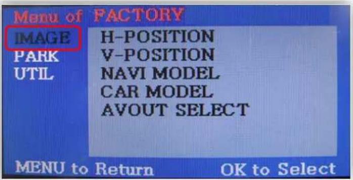
text_image
Menu of FACTORY IMAGE H-POSITION PARK V-POSITION UTIL NAVI MODEL CAR MODEL AVOUT SELECT MENU to Return OK to Select
text_image
POWER OFFIMAGE MENU
-The only setting that may need necessary adjustment here would be CAR MODEL (BMW/AUDI KITs)
Note: on some kits, this option is located under 'UTIL'
-The remaining settings are optional and install dependent.

text_image
MENU of FACTORY IMAGE PARK ENABLE PARK SETUP REAR SELECT SAFE ENABLE MENU to Return OK to SelectPARK MENU
PARK ENABLE: Rear-CAM guidelines ON/OFF
PARK SETUP: Rear-CAM guideline positioning
REAR SELECT: Change rear camera activation from CAN to LAMP (gray wire) Note: on some kits, this option is located under 'UTIL'
SAFE ENABLE: If 'ON', prevents AV sources from showing (unless you ground Blue 'PARKING' wire)

text_image
1 Rear-Select CAN to LAMP adjustment 2 MENI OF PACTORY(DU -130222) IMAGE PARK ENABLE PARK SETUP UTIL REAR SELECT SAFE ENABLE LAMP MENU to Return OK to SaveAgreement: End user agrees to use this product in compliance with all State and Federal laws. NAV-TV Corp. would not be held liable for misuse of its product. If you do not agree, please discontinue use immediately and return product to place of purchase. This product is intended for off-road use and passenger entertainment only.
FAQs
Q. I cannot switch A/V sources.
A. Check IR or toggle switch connection. Check the LEDs on the interface, if nothing is lit up with vehicle ignition, check power/ground connections.
Q. All I see on the display is a black screen (no factory image pass-through).
A. Make sure the video cables (IN/OUT) are connected at the proper location (Screen/Radio/NAV DRIVE).
B. Make sure the video cables are seated all the way.
C. Make sure Dip Switches 5 & 6 are set correctly (resolution or screen size).
Q. Displayed image color is not proper (too dim or color seems wrong).
A. Try to select 'INITIAL' in OSD menu.
Q. Rear camera image does NOT appear.
A. Make certain Dip Switch #7 in set down for aftermarket camera, or up for a factory camera.
B. Try swapping the CAN connection wires. This will not do damage, if it is hooked up wrong it will only not work.
C. Make certain the camera is properly powered. Check voltage at the camera itself.
D. Try an alternative video source, don't assume the power/ground is correct unless you've checked it with a multi-meter!
E. If this is a CAN-connected module and you've connected the CAN wires, try using the gray wire (not all interfaces have this wire!) instead of the CAN connection for reverse activation. You'll also need to change the Rear Select option in the Menu of Factory (MENU 2) under UTIL or PARK. Refer to the Menu Adjustments section.
Q. Unwanted A/V mode is displayed upon a toggle press (A/V source switching order: OEM->RGB->AV1->AV2->AV3->OEM).
A. Check DIP Switch Setting. Refer to page 2.