NVT-KIT422 - Dash cam NAV-TV - Free user manual and instructions
Find the device manual for free NVT-KIT422 NAV-TV in PDF.

User questions about NVT-KIT422 NAV-TV
0 question about this device. Answer the ones you know or ask your own.
Ask a new question about this device
Download the instructions for your Dash cam in PDF format for free! Find your manual NVT-KIT422 - NAV-TV and take your electronic device back in hand. On this page are published all the documents necessary for the use of your device. NVT-KIT422 by NAV-TV.
USER MANUAL NVT-KIT422 NAV-TV
Video in Motion, Control in Motion, Forced Cam
NTV-KIT422
natural_image
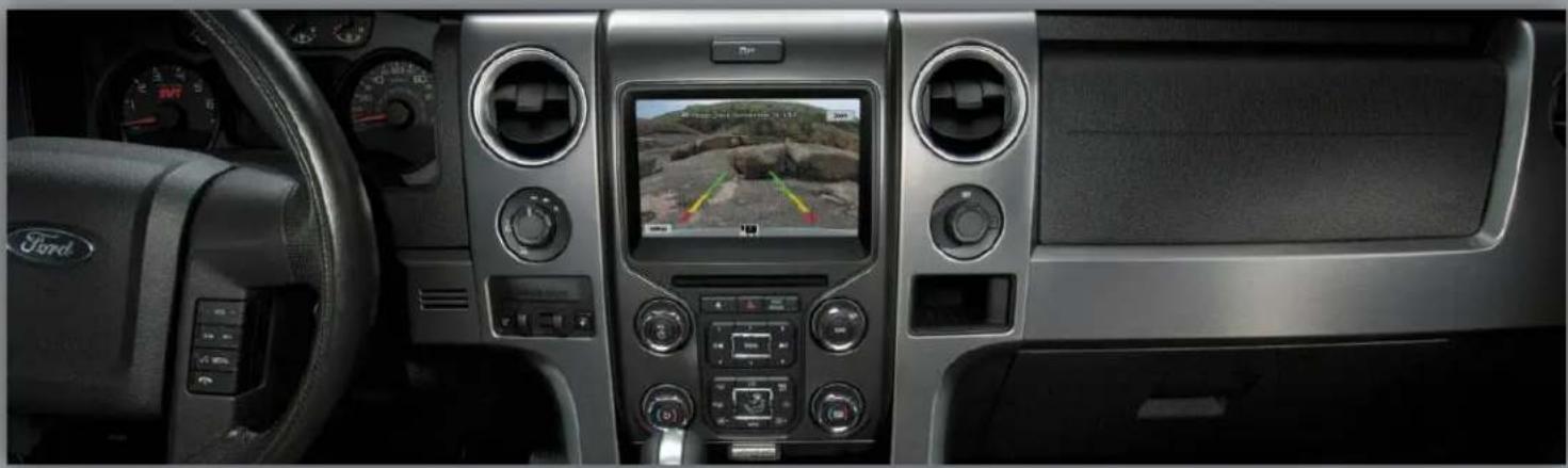
Interior view of a Ford car dashboard with digital displays and steering wheel (no visible text or symbols)
natural_image
Front-side view of a blue Ford-Turquoise pickup truck (no visible text or symbols)JR, BM
3/11/14
NTV-DOC155
Kit Contents

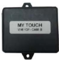
VIM modules A & B (2x)NTV-ASY166

natural_image
Coiled black cable with two USB ports (no text or symbols visible)USB cable (updates)
NTV-CAB009

natural_image
Coiled black cable with multicolored connectors and connectors, no visible text or symbolsPlug n' Play VIM Harness NTV-HAR241
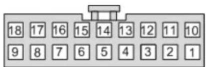
VIM A Connector Pin outs
| Pin # | Description | Color |
| 1 | 12v Constant Power (+) | Yellow |
| 2 | Input 1 | Red |
| 3 | Input 2 (Sending 12v will force rear camera) | Blue |
| 4 | External VIM Activation | Orange |
| 6 | LIN Break-Open wire (Camera Side) | Blue |
| 8 | CAN Hi (Radio Side) | Purple/Black |
| 9 | CAN Hi (Vehicle Side) | White/Black |
| 10 | Ground (-) | Black |
| 11 | 12v Output to VIM module B (pin 4) | Orange |
| 12 | Output 2 | Blue/White |
| 13 | Output 3 | White |
| 14 | Looped to pin 15 | Yellow |
| 15 | Looped to pin 14 | Yellow |
| 16 | LIN Break-Open wire (BCM Side) | Orange |
| 17 | CAN Lo (Radio Side) | Purple |
| 18 | CAN Lo (Vehicle Side) | White |

natural_image
Black rectangular electronic device with a small connector and mounting bracket (no visible text or symbols)
text_image
18 17 16 15 14 13 12 11 10 9 8 7 6 5 4 3 2 1Wire side
VIM B Connector Pin outs
| Pin # | Description | Color |
| 1 | 12v Constant Power (+) | Yellow |
| 4 | Input from VIM module A (pin 11) | Orange |
| 8 | CAN Hi – Radio Side | Green |
| 9 | CAN Hi – Vehicle Side | Gray |
| 10 | Ground (-) | Black |
| 17 | CAN Lo (Radio Side) | Green/Black |
| 18 | CAN Lo (Vehicle Side) | Gray/Black |
text_image
18 17 16 15 14 13 12 11 10 9 8 7 6 5 4 3 2 1Wire side
Agreement: End user agrees to use this product in compliance with all State and Federal laws. NAV-TV Corp. would not be held liable for misuse of its product. If you do not agree, please discontinue use immediately and return product to place of purchase. This product is intended for off-road use and passenger entertainment only.
VIM & F-CAM Installation
- Remove the factory My Ford Touch radio. This requires removing panels and various 7 & 8mm screws. The trim panels securing the center radio bezel do not need to be fully removed, just moved out of the way.
a. There are (2x) 7mm screws hidden beneath the airbag module and therefore the airbag module must be popped out (no need to disconnect entirely). Apply tape for protection to the dashboard just beneath the airbag before you do this!
b. Remove the passenger airbag assembly by removing the (3x) 8mm screws firing up from underneath the airbag. Access these screws by dropping the glove box down to the floor (again, no need to remove it entirely).
c. Remove (or pop free at the right bottom corner) the cluster surround, and pull aside the trim pieces that surround the radio.
-
Remove the (4x) 7mm screws holding the screen in place.
-
Disconnect all wiring and set the screen aside.
-
Gather the Plug & Play harness from the F-CAM kit.
-
Plug the main LCD harness (male) from the car into the female side of the F-CAM Plug & Play harness.
-
Gather the ‘A’ and ‘B’ modules, and connect them to their prospective, labeled connectors.

natural_image
Coiled black cable with various connectors and wires, no visible text or symbolsSteps 7-11 are intended for F150 Raptor's only, those with an OEM front camera. If are adding an aftermarket front camera to a standard F150, you must purchase NTV-KIT437 as well and should refer to that instruction set (pg 5&6) at this time before returning and completing the install here (begin again with step 12 upon returning).
-
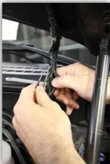
Under the driver's dash, make a small incision in the rubber harness grommet going through the firewall on the driver's side.
-
Connect a 10' pair of wires to the F-CAM module A: connect one of the wires to pin 6 and the other to pin 16. Route the free end of the wire pair through the firewall (at your incision), into the engine bay of the vehicle. Use silicon or 3M strip caulk to seal the incision.
-
On the underside of the hood, traveling down the driver's side, is the camera harness. Cut the harness open at the bottom of the hood.

natural_image
Close-up of mechanical components with visible wiring and a red arrow pointing to a component (no text or symbols)- Locate the gray/violet wire and cut it in half.
BHM 03/11/14 NTV-DOC155
natural_image
Close-up of hands installing or adjusting a black plastic component on a car hood (no visible text or symbols)- Connect the extended wire labeled "Camera" (pin 6), to the camera side of the cut gray/violet wire. Connect the extended wire labeled "BCM" (pin 16) to the vehicle side of the cut gray/violet wire. Insulate and tape the connections when finished.

text_image
Main Parking Grid Service for Hotel Settings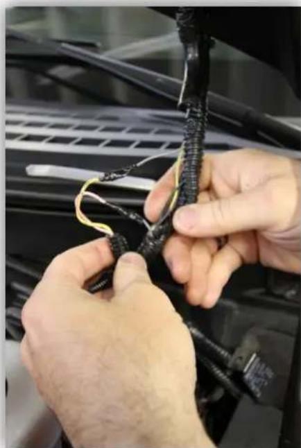
natural_image
Close-up of hands tying a black cable with yellow wires against a car hood (no visible text or symbols)- Plug the male end of the Plug & Play harness into the factory LCD and test for proper operation (refer to page 5 & 6 for operation instructions).
*Note: When the factory front camera is forced on, the active factory guidelines are not enabled. Only when the vehicle is in 4L will the active guidelines be available.
- Optional: If you send 12v (through a toggle) to Input 2 (Blue), it will force the rear camera.
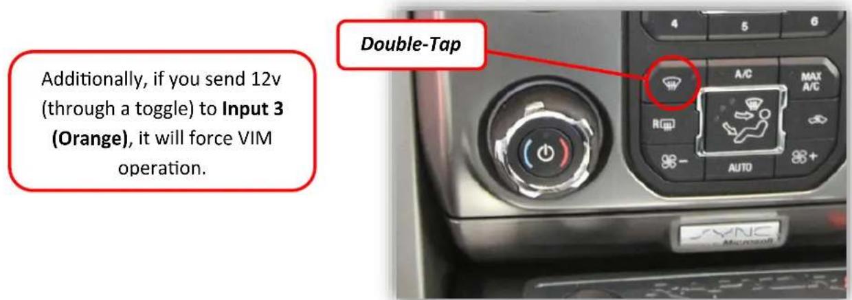
- Optional: If you send 12v (through a toggle) to Input 3 (Orange), it will force VIM operation.
VIM & F-CAM (Raptor) Install Diagram

flowchart
graph TD
    A["Used for front factory cam only (F-Series Raptor)"] --> B["A"]
    B --> C["Inputs/Outputs (refer to pinouts)"]
    C --> D["B"]
    D --> E["Plug n' Play Harness"]
    E --> F["Ford LCD"]
    E --> G["Car"]
Agreement: End user agrees to use this product in compliance with all State and Federal laws. NAV-TV Corp. would not be held liable for misuse of its product. If you do not agree, please discontinue use immediately and return product to place of purchase. This product is intended for off-road use and passenger entertainment only.
VIM & F-CAM Kit Operation
Video in Motion
When VIM is activated, AUX video input can be viewed while vehicle is in drive. This feature has to be enabled every time the key is cycled.
Video in Motion (VIM): Press the Front Defroster Button 2 times within 1 second.
text_image
Additionally, if you send 12v (through a toggle) to Input 3 (Orange), it will force VIM operation. Double-Tap A/C MAX A/C R AUTO SYNCForced Rear Camera
This function allows the viewing of an aftermarket rear camera at any time.
Forced Rear camera: Press Rear Defroster Button 2 times within 1 second.
Additionally, if you send 12v (through a toggle) to Input 2 (Blue), it will force the rear camera.

text_image
Double-TapAgreement: End user agrees to use this product in compliance with all State and Federal laws. NAV-TV Corp. would not be held liable for misuse of its product. If you do not agree, please discontinue use immediately and return product to place of purchase. This product is intended for off-road use and passenger entertainment only.
Factory Front Camera Operation
The front camera can be viewed at any time using the factory procedure for activation.
*Note: Front camera will not display if VIM is enabled!
text_image
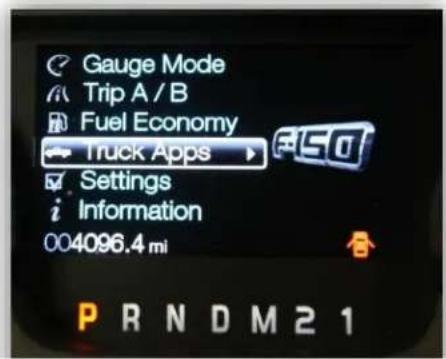
Gauge Mode Trip A / B Fuel Economy Truck Apps Settings Information 004096.4 mi PRNDM21- Using the steering wheel controls scroll down to the Truck Apps function in the instrument
text_image
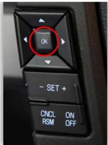
OK - SET + CNCL ON RSM OFF- Press the "OK" button on the steering wheel.

text_image
Off Road Camera Camera Disabled Press OK to Enable 004096.4 mi P R N D M 2 1- Scroll to the right until "Camera Disabled" is displayed.
text_image
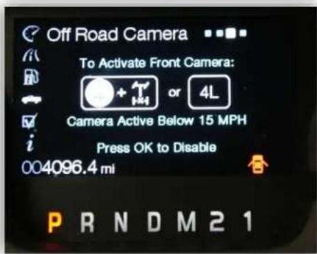
Off Road Camera To Activate Front Camera: or 4L Camera Active Below 15 MPH Press OK to Disable 004096.4 mi PRNDM21- The front camera will display on the screen (the active steering lines will not be displayed), the cluster will display 'Press OK to disable'
5. To disable front camera:
a. Make sure the cluster is on the Camera options screen
b. Press OK.