NVT-KIT511 - Dash cam NAV-TV - Free user manual and instructions
Find the device manual for free NVT-KIT511 NAV-TV in PDF.

User questions about NVT-KIT511 NAV-TV
0 question about this device. Answer the ones you know or ask your own.
Ask a new question about this device
Download the instructions for your Dash cam in PDF format for free! Find your manual NVT-KIT511 - NAV-TV and take your electronic device back in hand. On this page are published all the documents necessary for the use of your device. NVT-KIT511 by NAV-TV.
USER MANUAL NVT-KIT511 NAV-TV
Chrysler/Jeep Rear Camera Interface
NTV-KIT511

natural_image
Interior view of a modern car dashboard with steering wheel, dashboard gauges, and digital displays (no visible text or symbols)Comparable with 2014+ Jeep Cherokee
& 2015 Chrysler 200

natural_image
Exterior view of a blue SUV (no visible text or symbols)
natural_image
Exterior view of a modern white sedan (no visible text or symbols)BHM
09/11/14
NTV-DOC191
rR3
Overview
The UCT-PRG is a plug & play soluon for interfacing an aermarket rear camera into select Chrysler and Jeep vehicles. All connecons are made behind the factory radio/screen.
Kit Contents
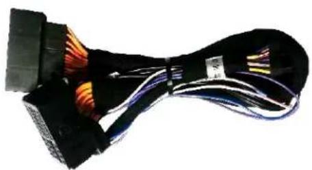
natural_image
Coiled black cable with multicolored wires, no visible text or symbolsPlug & Play T-harness NTV-HAR246

natural_image
Black rectangular electronic component with a small connector and mounting bracket (no visible text or symbols)UCT-PRG Module NTV-ASY166
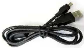
natural_image
Coiled black cable with two USB connectors (no text or symbols visible)USB Cable (updates) NTV-CAB009
UCT-PRG pin out
| PIN # | Descripon | Color |
| 1 | 12v (+) Constant | Yellow |
| 2 | Input 1 (N/A) | Red |
| 3 | Input 2 (N/A) | Blue |
| 4 | Input 3 (8.4" programming) | Pink |
| 6 | RCA MALE | -- |
| 7 | RCA Shield | -- |
| 8 | CAN HI (Radio Side) | White/Brown |
| 9 | CAN HI (Car Side) | White/Blue |
| 10 | Ground (-) | Black |
| 11 | Output 1 (12v ACC out) | White/Red |
| 12 | Output 2 (12v Reverse out) | Blue |
| 15 | RCA Female (Normally Open) | -- |
| 16 | RCA Female (Normally Closed) | -- |
| 17 | CAN LO (Radio Side) | Brown |
| 18 | CAN LO (Car Side) | Blue |

natural_image
Black rectangular electronic device with a small connector and mounting bracket (no visible text or symbols)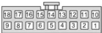
text_image
18 17 16 15 14 13 12 11 10 9 8 7 6 5 4 3 2 1Wire Side
All exisng wires not menoned here are NOT used for this installaon.
Agreement: End user agrees to use this product in compliance with all State and Federal laws. NAV-TV Corp. would not be held liable for misuse of its product. If you do not agree, please discontinue use immediately and return product to place of purchase. This product is intended for off-road use and passenger entertainment only.
Radio Removal ('14 Cherokee, 5" screen)
*Radio removal for other vehicles will be very similar.
- Begin by removing the climate control panel with a plasc tool.
- Disconnect the climate control harness and set the climate control aside.
- Next remove (2x) Phillips head screws that secure the radio fascia to the sub dash:
- Pull the vent shroud towards you aer removing the two boom screws. It is now held in by clips only:

text_image
removal for other I be very similar.
natural_image
Interior view of a car cab showing internal components and wiring (no visible text or symbols)
natural_image
Interior view of a car dashboard with digital display and control buttons (no visible text or symbols)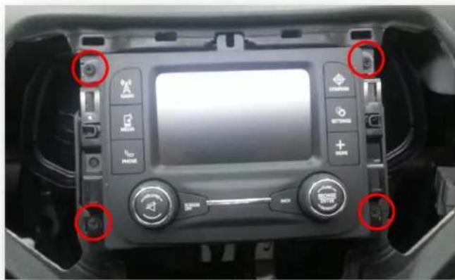
natural_image
Interior view of a car dashboard with digital display and control buttons (no visible text or symbols)- Remove (4x) Phillips head screws and pull the radio straight out of the dash. Disconnect all harnesses and set the radio aside.
Agreement: End user agrees to use this product in compliance with all State and Federal laws. NAV-TV Corp. would not be held liable for misuse of its product. If you do not agree, please discontinue use immediately and return product to place of purchase. This product is intended for off-road use and passenger entertainment only.
UCT-PRG Installaon / programming for 5" radio models
This guide is intended for 5" Radio models, DO NOT USE FOR 8.4" radio models!
- Verify the key is in the OFF posion (or not inserted) until step 6.
- Aer removing the factory radio, gather the Plug & Play T-harness and connect the female side to the factory 44-pin plug. Make certain the lock connects together securely.
- Aer installing a rear camera, connect the signal RCA to the yellow RCA on the male side (side going into monitor) of the Plug & Play T-harness. The other side of the yellow RCA can be le disconnected. *If the harness is shipped with the Audio (red & black) RCA's disconnected, be sure to plug the audio RCAs together. If le disconnected, the factory AUX audio jack will not pass through.
- Connect the UCT-PRG module to the 18-pin connector found in the Plug & Play T-harness.
-
Connect the radio to the male side of the Plug & Play T-harness. Reconnect all other plugs to the radio (see diagram on page 5).
-
Turn the key to the ON posion (don't start vehicle).
- The radio will turn on, and restart itself within 1 minute.
- Re-cycle the key one me (turn key to OFF then back again to ON). Wait for the radio to boot and sele.
- Cycle the ignition (o to ON) 3 mes (1 cycle/sec). Verify the odometer is not ashing.
- If programming of the radio took successfully, the camera image (or blue screen) will display on screen while in reverse.
Proper LED ashing indicaon: 1
2
^st Key cycle: 4 ashes
^nd and every following key cycle: 6 ashes
Below is a chart referencing LED ashes which can be found on the side of the UCT-PRG module. Refer here for troublesomeong.
| LED Response | Descripon |
| 1 ash | Waing for Ignion... (Turn ignition to ON) |
| 3 ashes | VIN Mismatch (This module has been used in a dierent vehicle already) |
| 4 ashes | First me programmed (Recycle ignition, then test for proper operaon) |
| 6 ashes | Programming complete (The radio has accepted the program) |
Agreement: End user agrees to use this product in compliance with all State and Federal laws. NAV-TV Corp. would not be held liable for misuse of its product. If you do not agree, please discontinue use immediately and return product to place of purchase. This product is intended for off-road use and passenger entertainment only.

natural_image
Black trophy with white cables and orange connectors, no visible text or symbolsUCT-PRG Installaon / programming for 8.4" radio models
This guide is intended for 8.4" Radio models, DO NOT USE FOR 5" radio models!
- Verify the key is in the OFF posion (or not inserted) unl step 6.
- Aer removing the factory radio, gather the Plug & Play T-harness and connect the female side to the factory 44-pin plug. Make certain the lock connects together securely.
- Aer installing a rear camera, connect the signal RCA to the yellow RCA on the male side (side going into monitor) of the Plug & Play T-harness. The other side of the yellow RCA can be le disconnected. *If the harness is shipped with the Audio (red & black) RCA's disconnected, be sure to plug the audio RCAs together. If le disconnected, the factory AUX audio jack will not pass through.
- Connect the UCT-PRG module to the 18-pin connector found in the Plug & Play T-harness.
- Connect the radio to the male side of the Plug & Play T-harness. Reconnect all other plugs to the radio (see diagram on page 5). Leave the module and input wires accessible.
- Turn the key to the ACC posion (not ON, don't start vehicle). Verify 1 LED ash.
- Temporarily connect input 3 (pink wire) to 12v (+).
- Turn the key to the ON posion. The radio will reboot within 20 seconds.
- While the radio is reboong, remove 12v (+) from input 3 (pink wire).
- Wait for the radio to boot and sele.
- Cycle the ignition (o to ON) 3 mes (1 cycle/sec). Verify the odometer is not ashing.
- If programming of the radio took successfully, the camera image (or blue screen) will display on screen while in reverse. If nothing happens in reverse, recycle the key and place the vehicle in reverse once more.
If this above procedure is not followed, the module will ash the LED 4 mes aer every key cycle and will not show a reverse image.
Below is a chart referencing LED ashes which can be found on the side of the UCT-PRG module. Refer here for troublesomeong.
| LED Response | Descripon |
| 1 ash | Waing for Ignion... (Turn ignition to ON) |
| 3 ashes | VIN Mismatch (This module has been used in a dierent vehicle already) |
| 4 ashes | First me programmed (Recycle ignition, then test for proper operaon) |
| 6 ashes | Programming complete (The radio has accepted the program) |

natural_image
Black trophy with white and orange ribbon, no visible text or symbolsAgreement: End user agrees to use this product in compliance with all State and Federal laws. NAV-TV Corp. would not be held liable for misuse of its product. If you do not agree, please discontinue use immediately and return product to place of purchase. This product is intended for off-road use and passenger entertainment only.
IMPORTANT NOTES:
• Proper LED ashing indicaon:
○ 1 ^st Key cycle: 4 ashes
○ Every following key cycle: 6 ashes
- This module locks to the vehicle's VIN and can only be used to program a reverse camera on ONE vehicle at a me.
- This module must remain in line (T-Harness) to this vehicle at all mes. If this kit is ever removed, the cluster will ash an error and the vehicle's system will need to be re-aligned from a dealer. NAV-TV is not responsible for incurred dealer fees due to installaon negligence!
- There is no way to de-program this module. Once programmed, this kit must remain in the vehicle forever! (The module will not work on another vehicle aer it has been programmed once!)
Installaon Diagram
FIG 1

flowchart
graph TD
    A["Car"] --> B["Plug & Play T-Harness"]
    C["Radio"] --> B
    B --> D["UCT-PRG"]
    D --> E["White/Red 12v ACC OUT (relay for camera power)"]
    D --> F["Input 3 8.4" Programming wire (page 5)"]
    G["Rear Camera"] --> B
Agreement: End user agrees to use this product in compliance with all State and Federal laws. NAV-TV Corp. would not be held liable for misuse of its product. If you do not agree, please discontinue use immediately and return product to place of purchase. This product is intended for off-road use and passenger entertainment only.
UCT-PRG Operaon
- Once installed, no user interacon is necessary. Any me the vehicle is placed into reverse, the rear-camera image will appear on screen.
- Note: Reverse image may stay on for a period of me aer the transmission of the vehicle is removed from reverse – this is a factory feature and is adjustable via the uConnect Sengs Menu*.
WARNING! (Continued)
- Before using the ParkSense® Active Park Assist system, it is strongly recommended that the ball mount and hitch ball assembly is disconnected from the vehicle when the vehicle is not used for towing. Failure to do so can result in injury or damage to vehicles or obstacles because the hitch ball will be much closer to the obstacle than the rear fascia when the loudspeaker sounds the continuous tone. Also, the sensors could detect the ball mount and hitch ball assembly, depending on its size and shape, giving a false indication that an obstacle is behind the vehicle.
OEM UConnect manual
UNDERSTANDING THE FEATURES OF YOUR VEHICLE 283
PARKVIEW® REAR BACK UP CAMERA — IF EQUIPPED
Your vehicle may be equipped with the ParkView® Rear Back Up Camera that allows you to see an on-screen image of the rear surroundings of your vehicle whenever the shift lever is put into REVERSE. The image will be displayed in the touchscreen display along with a caution note to "check entire surroundings" across the top of the screen. After five seconds this note will disappear. The ParkView® camera is located on the rear of the vehicle above the rear License plate.
NOTE: The ParkView® Rear Back Up Camera has programmable modes of operation that may be selected through the Uconnect® System. Refer to "Uconnect® Settings" in "Understanding Your Instrument Panel" for further information.
When the vehicle is shifted out of REVERSE (with camera delay turned OFF), the rear camera mode is exited and
284 UNDERSTANDING THE FEATURES OF YOUR VEHICLE
the navigation or audio screen appears again. When the vehicle is shifted out of REVERSE (with camera delay turned ON), the camera image will continue to be displayed for up to 10 seconds after shifting out of REVERSE unless the vehicle speed exceeds 8 mph (13 km/h), the vehicle is shifted into PARK or the vehicles ignition is cycled to the OFF position.
When enabled, active guide lines are overlaid on the image to illustrate the width of the vehicle and its projected backup path based on the steering wheel position. A dashed center line overlay indicates the center of the vehicle to assist with parking or aligning to a hitch/receiver.
When enabled, fixed guide lines are overlaid on the image to illustrate the width of the vehicle.
*While the OEM UConnect manual states that there are opons for guidelines (acve and stac), these will not be available with the UCT-PRG. These lines are generated by an OEM camera and cannot be emulated with an aermarket camera!
Agreement: End user agrees to use this product in compliance with all State and Federal laws. NAV-TV Corp. would not be held liable for misuse of its product. If you do not agree, please discontinue use immediately and return product to place of purchase. This product is intended for off-road use and passenger entertainment only.
NAV-TV
INTERFACING THE FUTURE

text_image
MADE IN U.S.A. PRODUCT
text_image
REGISTERED COMPANY ISO 9001 SGSAgreement: End user agrees to use this product in compliance with all State and Federal laws. NAV-TV Corp. would not be held liable for misuse of its product. If you do not agree, please discontinue use immediately and return product to place of purchase. This product is intended for off-road use and passenger entertainment only.