PU-444HBTE - Émetteur AV CYP - Free user manual and instructions
Find the device manual for free PU-444HBTE CYP in PDF.

User questions about PU-444HBTE CYP
0 question about this device. Answer the ones you know or ask your own.
Ask a new question about this device
Download the instructions for your Émetteur AV in PDF format for free! Find your manual PU-444HBTE - CYP and take your electronic device back in hand. On this page are published all the documents necessary for the use of your device. PU-444HBTE by CYP.
USER MANUAL PU-444HBTE CYP
natural_image
Black electronic device with control buttons and a digital display (no visible text or symbols)PU-444HBTE
4 x 8 HDMI / HDBaseT™ Matrix (4 x HDBaseT & 4 x HDMI Outputs, 5Play™ inc. PoE & Single LAN, up to 100m)
OPERATION MANUAL
DISCLAIMERS
The information in this manual has been carefully checked and is believed to be accurate. CYP (UK) Ltd assumes no responsibility for any infringements of patents or other rights of third parties which may result from its use.
CYP (UK) Ltd assumes no responsibility for any inaccuracies that may be contained in this document. CYP (UK) Ltd also makes no commitment to update or to keep current the information contained in this document.
CYP (UK) Ltd reserves the right to make improvements to this document and/or product at any time and without notice.
COPYRIGHT NOTICE
No part of this document may be reproduced, transmitted, transcribed, stored in a retrieval system, or any of its part translated into any language or computer file, in any form or by any means—electronic, mechanical, magnetic, optical, chemical, manual, or otherwise—without express written permission and consent from CYP (UK) Ltd.
© Copyright 2011 by CYP (UK) Ltd.
All Rights Reserved.
Version 1.1 August 2011
TRADEMARK ACKNOWLEDGMENTS
All products or service names mentioned in this document may be trademarks of the companies with which they are associated.
SAFETY PRECAUTIONS
Please read all instructions before attempting to unpack, install or operate this equipment and before connecting the power supply.
Please keep the following in mind as you unpack and install this equipment:
- Always follow basic safety precautions to reduce the risk of fire, electrical shock and injury to persons.
- To prevent fire or shock hazard, do not expose the unit to rain, moisture or install this product near water.
- Never spill liquid of any kind on or into this product.
- Never push an object of any kind into this product through any openings or empty slots in the unit, as you may damage parts inside the unit.
- Do not attach the power supply cabling to building surfaces.
- Use only the supplied power supply unit (PSU). Do not use the PSU if it is damaged.
- Do not allow anything to rest on the power cabling or allow any weight to be placed upon it or any person walk on it.
- To protect the unit from overheating, do not block any vents or openings in the unit housing that provide ventilation and allow for sufficient space for air to circulate around the unit.
REVISION HISTORY
VERSION NO. DATE SUMMARY OF CHANGE
| v1.00 14/04/2014 First release | ||
CONTENTS
- Introduction......6
- Applications ......6
- Package Contents ......6
- System Requirements ......7
- Features......7
- Operation Controls and Functions......8
6.1 Front Panel 8
6.2 Rear Panel....9
6.3 Side Panel....10
6.4 Remote Control....10
6.5 IR Pin Assignment....11
6.6 RS-232 Protocols....11
6.7 RS-232 & Telnet Commands......12
6.8 Telnet Control....14
6.9 Web GUI Control ....16
-
Connection Diagram ...... 18
-
Specifications......20
8.1 Technical Specification ......20
8.2 CAT5e/6/7 Cable Specification .....20
8.3 Input Timing Support Chart ......21
1. INTRODUCTION
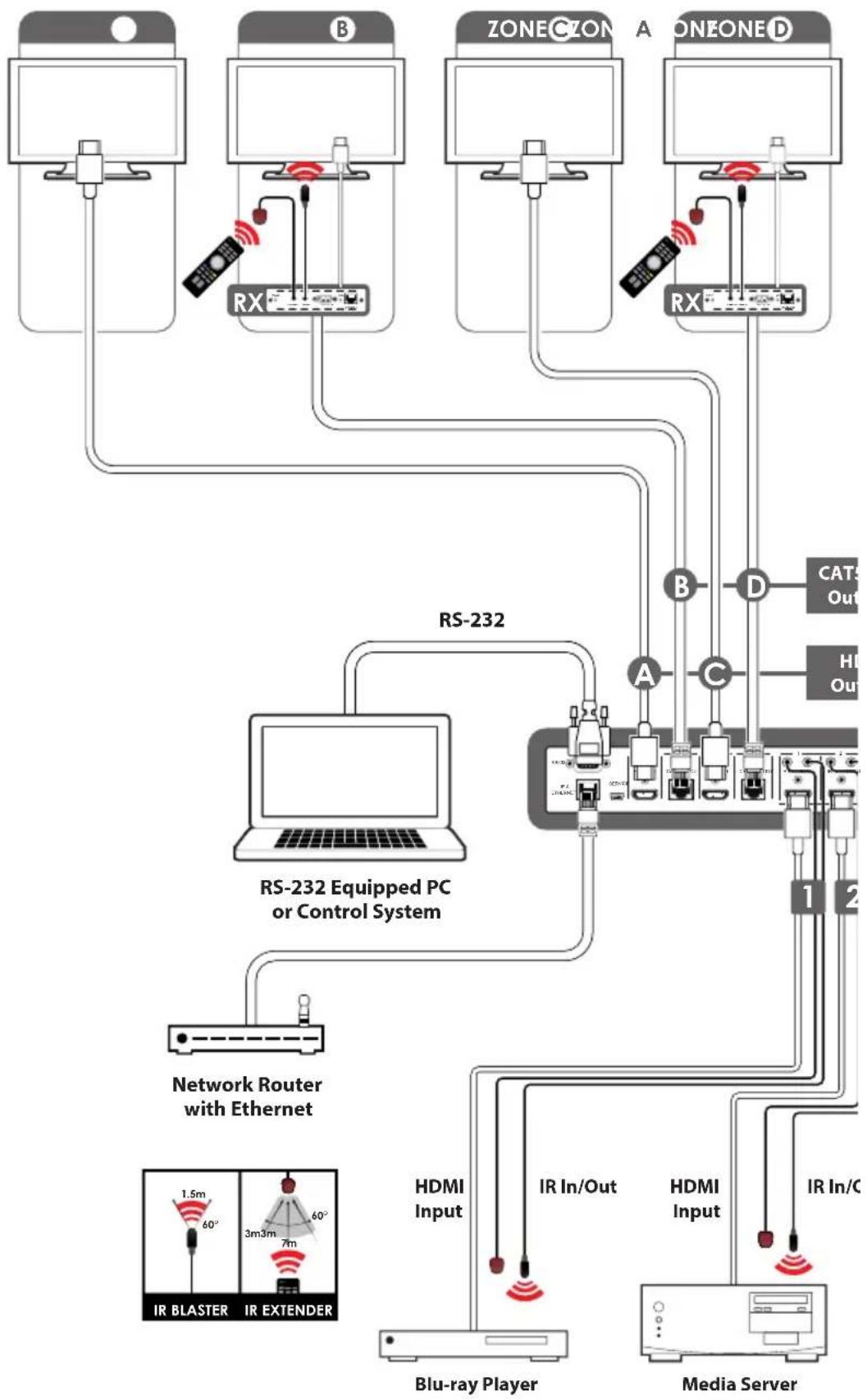
The PU-444HBTE Matrix enables distribution of four HDMI sources to four HDBaseT™ outputs and four HDMI outputs. Each input is independently routed to any output for maximum source to screen flexibility within any AV system. The four HDBaseT outputs support the transmission of video (resolutions up to 1080p Full HD and 1920x1200@60Hz), multi-channel audio, single LAN serving, and control via 2-way IR, RS-232 or Web GUI/Telnet IP over a single CAT5e/6/7 cable (up to 100m) for each output. HDMI outputs support the same video resolutions and high definition audio via certified HDMI cables up to 15m.
The HDBaseT outputs are designed to be used with any compatible HDBaseT Receiver as follows: PU-507RX / PU-507RX-2H / PU-507RX-SCD / PU-507WPRX / PU-1109RX. These Receivers support Power over Ethernet (PoE) function so do not require a separate PSU for power.
Use the LAN serving capabilities of the matrix to add internet connectivity to every HDBaseT output zone. In addition, this matrix also features IP control allowing users to access and control the matrix remotely and also allow additional options for integration of third-party control systems.
2. APPLICATIONS
HDMI system controls
Video/TV wall display and control
■ Security surveillance and control
Commercial advertising, displaying and control
Lecture room display and control
3. PACKAGE CONTENTS
1 x 4 by 8 Matrix
8 x IR Extender
8 x IR Blaster
x 24V/3.75A DC Power Supply
1 x Remote Control
1 x Operation Manual
4. SYSTEM REQUIREMENTS
Source equipment with HDMI connection cables
Certified CAT5e/6/7 cables
HDMI over CAT5e/6/7 receivers with Certified CAT5e/6/7 cables
Output displays or AV receivers with HDMI connection cables
5. FEATURES
HDMI, HDCP and DVI complaint
Common supported resolutions: HDTV: 480p, 576p, 720p, 1080i, 1080p, 1080p24; PC: VGA, SVGA, XGA, WXGA, SXGA, UXGA, WUXGA, 1920x1200@60Hz
High Definition Audio supported: Dolby TrueHD, Dolby Digital Plus and DTS-HD Master Audio plus LPCM (up to 192kHz)
Uncompressed data transfer over single CAT cable for HDBaseT outputs (100m - CAT6/7; 80m - CAT5e)
Supports HDMI input up to 15m 1080p 8bit or 10m 1080p 12bit.
Supports RS-232, 2-Way IR, Manual Selection Buttons, and Web GUI/Telnet IP for control
HDBaseT outputs support Power over Ethernet (PoE) with compatible receiver units
Selectable EDID settings - TV (downstream) and STD (fixed)
Supports LAN serving to all connected HDBaseT zones
Supports 3D signals
6. OPERATION CONTROLS AND FUNCTIONS
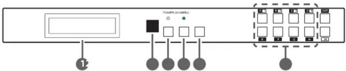
6.1 Front Panel
flowchart
graph LR
    A["Input"] --> B["Control"]
    B --> C["PowerlockMenu"]
    C --> D["Output"]
    style A fill:#f9f,stroke:#333
    style B fill:#ccf,stroke:#333
    style C fill:#cfc,stroke:#333
    style D fill:#fcc,stroke:#333
1 LCM: This monitor displays your setting information with each input and output selection.
2 IR: This IR window accepts the remote control signal of this device only.
3 Power Button & LED: Press this button to turn ON the device and the green LED will illuminate when the power is ON. When the LED illuminate in red it is in standby mode.
4 LCOK: Press this button to lock all the buttons on the panel and the LED will illuminate. To unlock, just press it again.
5 Menu: Press this button once to select EDID setting from STD(internal) 1 or TV(external) 2 then press it again to confirm the selection. Press this button every time to confirm the selection.
6 1\~4/A\~H & OUT/IN button: Press OUT/IN button first to select the output/input then press the number button to make the selection accordingly. For example, output A\~B wish to select input 1 and C\~E wish to select input 2. Press OUT→A→B→IN→1→Menu, and then press OUT→C→D→E→IN→2→Menu. If the menu button is not pressed the selection will not be changed.
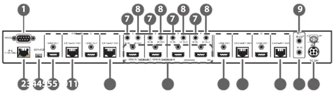
6.2 Rear Panel
flowchart
graph LR
    A["RIS208"] --> B["Service"]
    B --> C["1"]
    C --> D["2"]
    D --> E["3"]
    E --> F["4"]
    F --> G["5"]
    G --> H["6"]
    H --> I["7"]
    I --> J["8"]
    J --> K["9"]

    subgraph Port1
        L["RIS208"] --> M["Service"]
        M --> N["1"]
        N --> O["2"]
        O --> P["3"]
        P --> Q["4"]
        Q --> R["5"]
        R --> S["6"]
        S --> T["7"]
        T --> U["8"]
    end

    subgraph Port2
        V["RIS208"] --> W["Service"]
        W --> X["1"]
        X --> Y["2"]
        Y --> Z["3"]
        Z --> AA["4"]
        AA --> AB["5"]
        AB --> AC["6"]
        AC --> AD["7"]
        AD --> AE["8"]
    end

    subgraph Port3
        AF["RIS208"] --> AG["Service"]
        AG --> AH["1"]
        AH --> AI["2"]
        AI --> AJ["3"]
        AJ --> AK["4"]
        AK --> AL["5"]
        AL --> AM["6"]
        AM --> AN["7"]
        AN --> AO["8"]
    end

    subgraph Port4
        AP["RIS208"] --> AQ["Service"]
        AQ --> AR["1"]
        AR --> AS["2"]
        AS --> AT["3"]
        AT --> AU["4"]
        AU --> AV["5"]
        AV --> AW["6"]
        AW --> AX["7"]
        AX --> AY["8"]
    end

    subgraph Port5
        AZ["RIS208"] --> BA["Service"]
        BA --> BB["1"]
        BB --> BC["2"]
        BC --> BD["3"]
        BD --> BE["4"]
        BE --> BF["5"]
        BF --> BG["6"]
        BG --> BH["7"]
        BH --> BI["8"]
    end

    subgraph Port6
        BJ["RIS208"] --> BK["Service"]
        BK --> BL["1"]
        BL --> BM["2"]
        BM --> BN["3"]
        BN --> BO["4"]
        BO --> BP["5"]
        BP --> BQ["6"]
        BQ --> BR["7"]
        BR --> BS["8"]
    end

    subgraph Port7
        BT["RIS208"] --> BU["Service"]
        BU --> BV["1"]
        BV --> BW["2"]
        BW --> BX["3"]
        BX --> BY["4"]
        BY --> BZ["5"]
        BZ --> CA["6"]
        CA --> CB["7"]
        CB --> CC["8"]
    end

    subgraph Port8
        DA["RIS208"] --> DB["Service"]
        DB --> DC["1"]
        DC --> DD["2"]
        DD --> DE["3"]
        DE --> DF["4"]
        DF --> DG["5"]
        DG --> DH["6"]
        DH --> DI["7"]
        DI --> DJ["8"]
    end

    subgraph Port9
        DEA["RIS208"] --> BEB["RIS208"]
    end

    note1["=DMI 锁码 1/2 = HDMI 锁码 4"]
    note2["DC 24V"]
1 RS-232: This slot is to connect with D-Sub 9pin cable from the PC/Laptop device for RS-232 control.
Note: This RS-232 obtain routable function that is, from the Matrix it can send commands to all receivers or from receiver sides it can also send commands to control the Matrix. In order to allow the receivers to send command to control the Matrix, a null modern cable/adaptor is required. In order to allow the receivers to send command to control the Matrix, a null modern cable/adaptor is required.
2 IP & Ethernet: This port is for Telnet and Web GUI control. Connect and active network system with RJ45 terminated cable (for details, please refers to RS-232 & Telnet commands and Web GUI Control sections). Also, it allows Ethernet access when connecting to an active network source or when any of the CAT outputs has the Ethernet link.
Warning: Please do not connect this port directly to the PC/Laptop as the Telnet function will not work.
3 Service: This slot is to connect with mini USB B type cable for firmware update only.
4 HDMI OUT A/C/E/G: These slots are to connect with HD TV/display for instant display.
5 CAT5e/6/7 OUT B/D/F/H: These slots are to connect with HDMI over CAT5e/6/7 Receiver for signal extension up to 100m.
6 HDMI IN 1\~4: These slots are to connect to input source equipment such as DVD player or Set-Top-Box with HDMI cable or DVI to HDMI converter cable for input signal sending.
7 IR IN 1\~4: These slots are to connect with IR Extender included in the package for IR signal receiving.
8 IR OUT 1\~4: These slots are to connect with IR Blaster included in the package for IR signal sending.
9 ALL IR OUT: This slot is to connect with the IR Blaster for IR signal received from receiver sides and send to the source side.
10 ALL IR IN: This slot is to connect with the IR extender for IR signal receiving and send out to receiver sides.
11 DC24V: This slot is to plug the power cord with adaptor included in the package and then connect them with AC wall outlet for power supply.
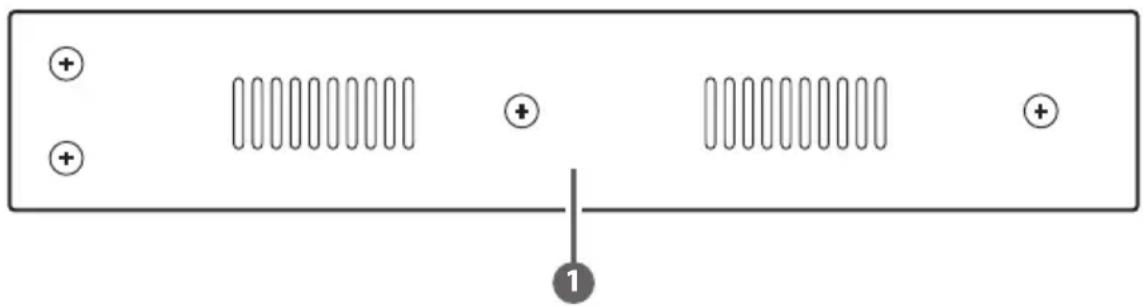
6.3 Side Panel
natural_image
Pure electrical circuit lines without any symbols1 Ventilator: These are fan ventilator area, DO NOT block these area or cover it with any object.
6.4 Remote Control
1 Power: Press this button to switch ON the device or set it to standby mode.
2 IN: Input ports selection 1\~4.
3 OUT: Output ports selection A\~H.

text_image
1 2 3 4 5 6 7 8 INOUT A B C D E F G H CR-1106.5 IR Pin Assignment

text_image
IR Blaster 1 Power 5V 2 IR Blaster Signal 3 NC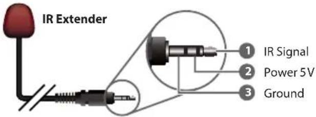
text_image
IR Extender 1 IR Signal 2 Power 5V 3 Ground6.6 RS-232 Protocols
| PU-444HBTE Remote Cont | |
| PIN Assignment | PIN Assignment |
| 1 NC 1 NC | |
| 2 Tx 2 Rx | |
| 3 Rx 3 Tx | |
| 4 NC 4 NC | |
| 5 GND 5 GND | |
| 6 NC 6 NC | |
| 7 NC 7 NC | |
| 8 NC 8 NC | |
| 9 NC 9 NC | |
| nsole | |
Baud Rate: 19,200bps
Data bit: 8 bits
Parity: None
Flow Control: None
Stop Bit: 1
6.7 RS-232 & Telnet Commands
| Command Description | |
| A1~A4 Switch output A to 1 | ~4 |
| B1~B4 Switch output B to 1 | ~4 |
| C1~C4 Switch output C to 1 | ~4 |
| D1~D4 Switch output D to 1 | ~4 |
| E1~E4 Switch output E to 1 | ~4 |
| F1~F4 Switch output F to 1 | ~4 |
| G1~G4 Switch output G to 1 | ~4 |
| H1~H4 Switch output H to 1 | ~4 |
| A0~H0 Switch output A to F mute | |
| ABCD...1~ABCD...4 Switch output ABCD... to 1~4 | |
| ABCD....0 Mute output ABCD... at the same time | |
| SETIP<IP><SubNet><GW> | Setting IP. SubNet. GateWay (Static IP) |
| RSTIP IP Configuration Was | Reset to Factory Defaults |
| IPCONFIG Display the current IP configuration | |
| P0 POWER OFF | |
| P1 POWER ON | |
| I1~I4 | Switch all the output to 1~4 |
| I0 | Mute all the output |
| ST | Display the current matrix status and F/W version |
| RS System Reset to A1, B1, C2, D2, E3, F3, G4, H4 | |
| EM | Setting EDID MODE. 1-STD 2-TV |
| ? | Display all the available commands |
| UARTBAUD? Display baud rate setting 1~61: 9600bps2: 14400bps3: 19200bps4: 38400bps5: 57600bps6: 115200bps | |
| UARTBAUD2 Set output B's | baud rate from 1~6 |
| UARTBAUD4 Set output D's | baud rate from 1~6 |
| UARTBAUD6 Set output H's | baud rate from 1~6 |
| UARTBAUD8 Set output H's | baud rate from 1~6 |
| UARTSW? Display output's | UART status Allowing Matrix to send commands to Receiver's connected device. |
| UARTSW0 Switch to MCU. | Allowing Receivers to send commands to Matrix. |
| UARTSW2 Switch to output | B and allow Matrix to send commands to Receiver's connected device. |
| UARTSW4 Switch to output | D and allow Matrix to send commands to Receiver's connected device. |
| UARTSW6 Switch to output | F and allow Matrix to send commands to Receiver's connected device. |
| UARTSW8 Switch to output | H and allow Matrix to send commands to Receiver's connected device. |
| Quit Exit (for telnet only) | |
Note: Commands will be not executed unless followed by a carriage return. All commands are not case-sensitive. Commands are under RS-232 control only.
6.8 Telnet Control
Before attempting to use the telnet control, please ensure that both the Matrix (via the 'CONTROL' port) and the PC/Laptop are connected to the active networks.
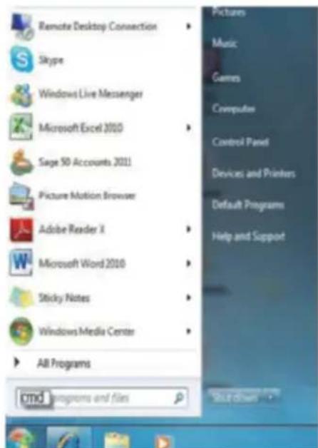
To access the telnet control in Windows 7, click on the 'Start' menu and type "cmd" in the Search field then press enter
Under Windows XP go to the 'Start' menu and click on "Run", type "cmd" with then press enter.
Under Mac OS X, go to Go→Applications→Utilities→Terminal See below for reference.
text_image
Remote Desktop Connection Skype Windows Live Messenger Microsoft Excel 2010 Sage 50 Accounts 2011 Picture Motion Browser Adobe Reader X Microsoft Word 2010 Sticky Notes Windows Media Center All Programs cmd programs and files Pictures Music Games Computers Control Panel Devices and Printers Default Programs Help and Support Shut drives
text_image
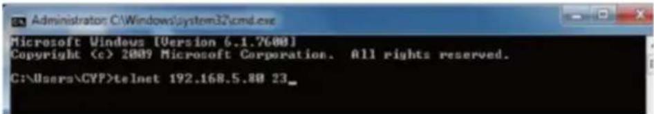
Finder File Edit View Go Window Help Back ⌘1 Forward ⌘1 Select Startup Disk on Desktop ⌘1 Computer ⌘0C Home ⌘0H Desktop ⌘0D Network ⌘0K iDisk ⌘> Applications ⌘A Documents ⌘0D Utilities ⌘0U Recent Folders ⌘ Go to Folder... ⌘0C Connect to Server... ⌘KOnce in the command line interface (CLI) type "telnet", then the IP address of the unit and "23", then hit enter.
Note: The IP address of the Matrix can be displayed on the device's LCM monitor by pressing the Menu button twice.
text_image
Administrator: C:\Windows\system32\cmd.exe Microsoft Windows [Version 6.1.7600] Copyright (c) 2009 Microsoft Corporation. All rights reserved. C:\Users\CYP>telnet 192.168.5.80 23_This will bring us into the device which we wish to control. Type "HELP" to list the available commands.

text_image
Welcome to PU-444HBTE TELNET. telnet-> help A1^A4 : Switch Output A to 1^4 B1^B4 : Switch Output B to 1^4 C1^C4 : Switch Output C to 1^4 D1^D4 : Switch Output D to 1^4 E1^E4 : Switch Output E to 1^4 F1^F4 : Switch Output F to 1^4 G1^G4 : Switch Output G to 1^4 H1^H4 : Switch Output H to 1^4 A0^H0 : Switch Output A to H mute ABCD...1^ABCD...4 : Switch output ABCD... to 1^4 at the same time ABCD...0: Mute output ABCD... at the same time SETIPType "IPCONFIG" To show all IP configurations. To reset the IP, type "RSTIP" and to use a set static IP, type "SETIP" (For a full list of commands, see Section 6.7).
Note: All the commands will be not executed unless followed by a carriage return. Commands are case-insensitive. If the IP is changed then the IP Address required for Telnet access will also change accordingly.
6.9 Web GUI Control
On a PC/Laptop that is connected to the active network as the Matrix, open a web browser and type device's IP address on the web address entry bar. The browser will display the device's status, control and User setting pages.

text_image
CYP PU-444HBTE Status Cancel Out Setting CYP PU-444HBTE Power Status Power Status ON IP Status IP Address 192.168.5.77 Network Address 265.255.255.0 Gateway Address 192.168.5.234 MAC Address F8-22-85-00-03-60 Imp Port Number 30 Tahst Port Number 23 Matrix Status Output Port A Input Port 1 Output Port B Input Port 1 Output Port C Input Port 2 Output Port D Input Port 2 Output Port E Input Port 3 Output Port F Input Port 3 Output Port G Input Port 4 Output Port H Input Port 4 EDID Mode EDID Mode TVClick on the 'Control' tab to control power, input/output ports, EDID and reset mode.

text_image
Control 192.168.5.77/control.shtml CYP PU-444HBTE Power Control POWERFUL POWERCAP Matrix Control Output Port A Input Port 1 Output Port B Input Port 1 Output Port C Input Port 2 Output Port D Input Port 2 Output Port E Input Port 3 Output Port F Input Port 3 Output Port G Input Port 4 Output Port H Input Port 4 All Output Set Tx Select Input Port EDID Mode 2-TV System Reset ResetClicking on the 'User Setting' tab allows you to reset the IP configuration. The system will ask for a reboot of the device every time any of the settings are changed. The IP address needed to access the Web GUI control will also need to be changed accordingly on the web address entry bar.

text_image
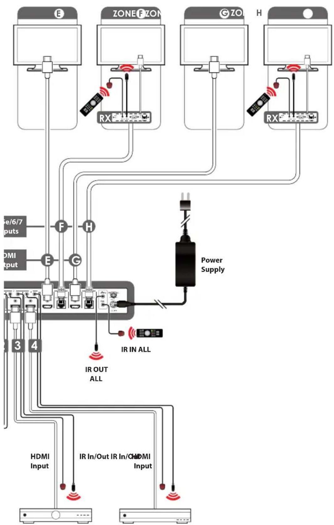
CYP PU-444HBTE IP Address Selection Address Type: DHCPAutoIP Static 102 168 5 IPAddress 77 Submit Mark: 255 255 255 Default 102 168 5 Gateway 254 Update Settings- CONNECTION DIAGRAM
flowchart
graph TD
    subgraph_RS-232["RS-232 Equipped PC or Control System"]
        A["Network Router with Ethernet"] --> B["Blu-ray Player"]
        B --> C["HDMI Input"]
        C --> D["IR In/Out"]
        D --> E["Media Server"]
    end

    subgraph_ZoneZone["ZoneCZON"]
        F["Node 1"] --> G["Node 2"]
        H["Node 2"] --> I["Node 3"]
        J["Node 3"] --> K["Node 4"]
        L["Node 4"] --> M["Node 5"]
        N["Node 5"] --> O["Node 6"]
        P["Node 6"] --> Q["Node 7"]
        R["Node 7"] --> S["Node 8"]
        T["Node 8"] --> U["Node 9"]
        V["Node 9"] --> W["Node 10"]
        X["Node 10"] --> Y["Node 11"]
        Z["Node 11"] --> AA["Node 12"]
        AB["Node 12"] --> AC["Node 13"]
        AD["Node 13"] --> AE["Node 14"]
        AF["Node 14"] --> AG["Node 15"]
        AH["Node 15"] --> AI["Node 16"]
        AJ["Node 16"] --> AK["Node 17"]
        AL["Node 17"] --> AM["Node 18"]
        AN["Node 18"] --> AO["Node 19"]
        AP["Node 19"] --> AQ["Node 20"]
        AR["Node 20"] --> AS["Node 21"]
        AT["Node 21"] --> AU["Node 22"]
        AV["Node 22"] --> AW["Node 23"]
        AX["Node 23"] --> AY["Node 24"]
        AZ["Node 24"] --> BA["Node 25"]
        BB["Node 25"] --> BC["Node 26"]
        BD["Node 26"] --> BE["Node 27"]
        BF["Node 27"] --> BG["Node 28"]
        BH["Node 28"] --> BI["Node 29"]
        BJ["Node 29"] --> BK["Node 30"]
        BL["Node 30"] --> BM["Node 31"]
        BN["Node 31"] --> BO["Node 32"]
        BP["Node 32"] --> BQ["Node 33"]
        BR["Node 33"] --> BS["Node 34"]
        BT["Node 34"] --> BU["Node 35"]
        BV["Node 35"] --> BW["Node 36"]
        BX["Node 36"] --> BY["Node 37"]
        BZ["Node 37"] --> CA["Node 38"]
        CB["Node 38"] --> CC["Node 39"]
        DD["Node 39"] --> EE["Node 40"]
        FF["Node 40"] --> DG["Node 41"]
        DH["Node 41"] --> DI["Node 42"]
        DJ["Node 42"] --> DK["Node 43"]
        DL["Node 43"] --> DV["Node 44"]
        DW["Node 44"] --> DX["Node 45"]
        DXN["Node 45"] --> DY["Node 46"]
        DYND["Airbus/Inverter"] --> BX
    end

    style RS-232 fill:#f9f,stroke:#333
    style ZoneZone fill:#ccf,stroke:#333
    style ZoneONE fill:#cfc,stroke:#333
    style ZoneBLAST fill:#fcc,stroke:#333
    style ZoneEXTENDER fill:#cff,stroke:#333
    style BLU-RayPlayer fill:#ffc,stroke:#333
    style MediaServer fill:#fcc,stroke:#333
    style MediaServer fill:#fcc,stroke:#333
    style MediaServer fill:#fcc,stroke:#333
    style MediaServer fill:#fcc,stroke:#333
    style MediaServer fill:#fcc,stroke:#333
    style MediaServer fill:#fcc,stroke:#333
    style MediaServer fill:#fcc,stroke:#333
    style MediaServer fill:#fcc, stroke:#333
    style MediaServer fill:#fcc,stroke:#333
    style MediaServer fill:#fcc,stroke:#333
    style MediaServer fill:#fcc,stroke:#333
    style MediaServer fill:#fcc,stroke:#333
    style MediaServer fill:#fcc,stroke:#333
    style MediaServer fill:#fcc,stroke:#333
    style MediaServer fill:#fcc,stroke:#�33
    style MediaServer fill:#fcc,stroke:#333
    style MediaServer fill:#fcc,stroke:#333
    style MediaServer fill:#fcc,stroke:#333
    style MediaServer fill:#fcc,stroke:#333
    style MediaServer fill:#fcc,stroke:#333
    style MediaServer fill:#fcc,stroke:#333
    style MediaServer fill:#fcc,stroke:#334
flowchart
graph TD
    subgraph Device_E
        E1["Computer"] --> RX1["RX"]
        ZONE_FZON["ZONE F ZON"] --> RX2["RX"]
        GZO["G ZO"] --> RX3["RX"]
        H["H"] --> RX4["RX"]
    end

    subgraph Device_F
        E5["Computer"] --> RX5["RX"]
        ZONE_FZON --> RX6["RX"]
        GZO --> RX7["RX"]
        H --> RX8["RX"]
    end

    subgraph Device_G
        E9["Computer"] --> RX9["RX"]
        ZONE_FZON --> RX10["RX"]
        GZO --> RX10
        H --> RX10
    end

    subgraph Power_Traffic
        IROUT["IR OUT ALL"] --> IRINALL["IR IN ALL"]
    end

    subgraph HDMI_Traffic
        IRInOut["IR In/Out IR In/Off HDMI Input"] --> IRINOUT
    end

    style Device_E fill:#f9f,stroke:#333
    style ZONE_FZON fill:#ccf,stroke:#333
    style GZO fill:#cfc,stroke:#333
    style H fill:#fcc,stroke:#333
    style IROUT fill:#ffc,stroke:#333
    style IRINOUT fill:#cfc,stroke:#333
    style HDMI_Traffic fill:#fff,stroke:#333
BoxSatellite Receiver
8. SPECIFICATIONS
8.1 Technical Specification
Video Bandwidth 225MHz/6.75Gbps
Input Ports 4 x HDMI, 5 x IR Extender, 1 x RS-232, 1 x LAN
(Control only), 1 x RJ45 (Control Only), 1 x USB
Mini-B (Service Only)
Output Ports 4 x HDMI, 4 x CAT5e/6/7, 5 x IR Blaster
Power Supply 24V / 3.75A DC (US/EU standards, CE/FCC/UL
certified)
ESD Protection Human Body model:
± 8kV (air-gap discharge)
± 4kV (contact discharge)
Dimensions (mm) 436(W) x 249(D) x 44(H)
436(W) x 255(D) x 48(H)/Including Jacks
Weight 3344g
Chassis Material Metal
Colour Black
Operating Temperature 0°C\~40°C / 32°F \~ 104°F
Storage temperature -20°C\~60°C / -4°F \~ 140°F
Relative Humidity 20\~90% RH (no condensation)
Power Consumption 40W
8.2 CAT5e/6/7 Cable Specification
| Cable Type | Range | Pixel clock rate | Video Data Rate | Supported Video |
| CAT5e/6/7 | 100 m | <=225 MHz | <=5.3 Gbps (HD Video) | Up to 1080p, 60 Hz, 36 bits, 3D (data rates lower than 5.3 Gbps or below 225 MHz TMDS clock). |
8.3 Input Timing Support Chart
| HDMI Supported Input Resolutions | ||||
| Resolution Timing | Vertical Frequency(Hz) | Pixel Rate (MHz) | HDMI Support | Video Standard |
| 640x480@60 60.00 | 25.175 | √ | VESA | |
| 640x480@72 72.00 | 31.500 | √ | VESA | |
| 640x480@75 75.00 | 31.500 | √ | VESA | |
| 640x480@85 | 85.00 | 36.000 | √ | VESA |
| 720x400@85 85.00 | 35.500 | √ | VESA | |
| 800x600@56 56.00 | 36.000 | √ | VESA | |
| 800x600@60 60.00 | 40.000 | √ | VESA | |
| 800x600@72 72.00 | 50.000 | √ | VESA | |
| 800x600@75 75.00 | 49.500 | √ | VESA | |
| 800x600@85 85.00 | 56.250 | √ | VESA | |
| 1024x768@60 60.00 | 65.000 | √ | VESA | |
| 1024x768@70 70.00 | 75.000 | √ | VESA | |
| 1024x768@75 75.00 | 78.750 | √ | VESA | |
| 1024x768@85 85.00 | 94.500 | √ | VESA | |
| 1152x864@75 75.00 | 108.000 | √ | VESA | |
| 1280x720@60 60.00 | 74.250 | √ | VESA | |
| 1280x768@60 60.00 | 79.500 | √ | VESA | |
| 1280x768@75 75.00 | 102.250 | √ | VESA | |
| 1280x768@85 85.00 | 117.500 | √ | VESA | |
| 1280x800@60RB 60.00 | 71.000 | — | VESA | |
| 1280x800@60 60.00 | 83.500 | — | VESA | |
| 1280x960@60 60.00 | 108.000 | √ | VESA | |
| 1280x1024@60 60.00 | 108.000 | √ | VESA | |
| 1360x768@60 60.00 | 85.500 | √ | VESA | |
| 1366x768@60 60.00 | 85.500 — VESA | |||
| 1400x1050@60RB 60.00 | 101.000 | √ | VESA | |
| 1400x1050@60 60.00 | 121.750 | √ | VESA | |
| 1440x900@60RB 60.00 | 88.750 — VESA | |||
| 1440x900@60 60.00 | 106.500 — VESA | |||
| 1600x900@60 60.00 | 108.000 — VESA | |||
| 1600x1200@60 60.00 | 162.000 — VESA | |||
| 1680x1050@60RB 60.00 | 119.000 — VESA | |||
| 1680x1050@60 60.00 | 146.250 — VESA | |||
| 1920x1080@60 60.00 | 148.500 | √ | VESA | |
| 1920x1200@60RB 60.00 | 154.000 | √ | VESA | |
HDMI Supported Input Resolutions
| Resolution Timing | Vertical Frequency(Hz) | Pixel Rate (MHz) | HDMI Support | Video Standrad |
| 1440x576i@50 50.00 | 27.000 | √ | CEA | |
| 1440x480i@59.94 59.94 | 27.000 | √ | CEA | |
| 1440x480i@60 60.00 | 27.028 | √ | CEA | |
| 720x480p@59.94 59.94 | 27.000 | √ | CEA | |
| 720x480p@60 60.00 | 27.027 | √ | CEA | |
| 720x576p@50 50.00 | 54.000 | √ | CEA | |
| 1280x720p@50 50.00 | 74.250 | √ | CEA | |
| 1280x720p@59.94 59.94 | 74.176 | √ | CEA | |
| 1280x720p@60 60.00 | 74.250 | √ | CEA | |
| 1920x1080i@50 50.00 | 74.250 | √ | CEA | |
| 1920x1080i@59.94 59.94 | 74.176 | √ | CEA | |
| 1920x1080i@60 60.00 | 74.250 | √ | CEA | |
| 1920x1080p@50 50.00 | 148.500 | √ | CEA | |
| 1920x1080p@59.94 59.94 | 148.352 | √ | CEA | |
| 1920x1080p@60 60.00 | 148.500 | √ | CEA | |
| 1920x1080p@23.97 23.97 | 74.176 | √ | CEA | |
| 1920x1080p@24 24.00 | 74.250 | √ | CEA | |
| 1920x1080p@25 25.00 | 74.250 | √ | CEA | |
| 1920x1080p@29.97 29.97 74.176 | √ | CEA | ||
| 1920x1080p@30 30.00 74.250 | √ | CEA |

CYP (UK) Ltd., Unit 7, Shepperton Business Park, Govett Avenue, Shepperton, Middlesex, TW17 8BA
Tel: +44 (0) 20 3137 9180 | Fax: +44 (0) 20 3137 6279
Email: sales@cypeurope.com
www.cypeurope.com
v1.00