SHR-2042P2 - Speaker SAMSUNG - Free user manual and instructions
Find the device manual for free SHR-2042P2 SAMSUNG in PDF.

User questions about SHR-2042P2 SAMSUNG
0 question about this device. Answer the ones you know or ask your own.
Ask a new question about this device
Download the instructions for your Speaker in PDF format for free! Find your manual SHR-2042P2 - SAMSUNG and take your electronic device back in hand. On this page are published all the documents necessary for the use of your device. SHR-2042P2 by SAMSUNG.
USER MANUAL SHR-2042P2 SAMSUNG
SHR-2040/2041/2042 User's Manual
Safety Regulations
Please be sure to keep the following in mind for the right use of the product to pre-vent proprietary risk or damage.
■ Do not use multiple plugs at once.
● This may cause abnormal heat generation or fire
■ Do not put a vase, flowerpot, cup, cosmetics, medicine, or vessel with water around you.
● This may cause fire.
■ Do not bend the power cord forcibly nor put a heavy material on it.
- This may cause fire.
■ Do not touch the power plug with wet hands.
● This may cause electric shock.
■Insert the power plug firmly enough not to shake.
● This imperfect connection may cause fire.
- Keep the product off humidity, dust, or soot.
● This may cause fire or electric shock.
■ Do not put metals(coin, hair pin, metal piece, etc.) or inflammable materials(match, paper, etc.) in the ventilation hole.
● This may cause fire.
- Keep the surrounding temperature between 0°C to 40°C and keep the product off humidity.
● This may cause breakdown.
■ Secure sufficient ventilation.
● This may cause abnormal operation due to high temperature.
- Keep the product off direct ray of light or heat from the heating device
● This may cause fire.
■ Do not disassemble, repair, or remodel the product.
● This may cause fire, electric shock, or injury due to abnormal operation.
■ Do not pull out the power cord.
- This may destroy the power cord, eventually, cause fire or electric shock.
■ Plug out in the event of thunder or lightning.
- This may cause fire.

- Keep your children off the battery after you take it out of the product. They tend to swallow it unconsciously.
- If your children swallow it, please see the doctor immediately.
■ Install the product at a safe place or attach the product to the wall or ceiling with a stand firmly enough not to fall to the ground.
● This may injure people.
Before we start
This User's Manual describes the basic usage of SHR-2040/2041/2042.
This Manual contains all the matters necessary for using SHR-2040/2041/2042 such as brief instruction, part name, function, connecting other equipment, and menu setup of SHR-2040/2041/2042.
SEC retains the copyright on this User's Manual.
- This User's Manual cannot be copied without SEC's prior written approval.
- We are not liable for any or all losses to the product incurred by your use of non-standard product or violation of User's Manual.
- If you want to open the system case to touch the inside, please consult with an expert who works for the shop where you bought the product.
- You may download open source codes from the following website. (See CCTV Part of http://www.samsung.com)
- Before installing any external device such as external memory or HDD, please check the compatibility of the device with Samsung DVR. The list of the compatible devices with Samsung DVR can be obtained from your vendor.
- Apparatus shall not be exposed to dripping or splashing and no objects filled with liquids, such as vases, shall be placed on the apparatus.
- The Mains plug is used as a disconnect device and shall stay readily operable at any time.
WARNING
[Battery]
As wrong exchange of the battery in SHR-2040/2041/2042 may cause explosion, you shall use the certified battery for SHR-2040/2041/2042.
The battery specification is as follows.
-Normal Voltage : 3V
-Normal Capacity : 170mAh
-Continuous Standard Load : 0.2mA
-Operating Temperature: -20 to +85°C
(-4 to +185°F)
CALIFORNIA USA ONLY
This Perchlorate warning applies only to primary CR (Manganese Dioxide) Lithium coin cells in the product sold or distributed ONLY in California USA "Perchlorate Material - special handling may apply, See www.dtsc.ca.gov/hazardouswaste/perchlorate."
[System Shutdown]
- Power-off without terminating the system in the System Shutdown menu may incur improper motion like data loss and disk failure. Also it can cause a dysfunction to the hard disk while using the product. Power-off shall be done in the System Shutdown menu.
[Operation warranty temperature]
- Operation warranty temperature of this device is 0^ C to 45^ C( 32^ F to 104^ F). If the device is left under the warranty temperature for a long time, it cannot be operated. When using the device after leaving for a long time in the low temperature, please use it after keeping in the normal temperature for a few times. Especially the warranty temperature of the embedded HDD is 5^ C to 55^ C( 41^ F to 131^ F), therefore it cannot be operated in the low temperature.
Standards Approvals


Note : This equipment has been tested and found to comply with the limits for a Class A digital device, pursuant to part 15 of the FCC Rules.
These limits are designed to provide reasonable protection against harmful interference when the equipment is operated in a commercial environment. This equipment generates, uses, and can radiate radio frequency energy and, if not installed and used in accordance with the instruction manual, may cause harmful interference to radio communications. Operation of this equipment in a residential area is likely to cause harmful interference in which case the user will be required to correct the interference at his own expense.
Contents
ii
iii
1
1-1
1-2
1-3
2
2-1
2-3
2-4
3
3-1
3-3
3-5
3-6
3-8
4
4-1
4-2
4-5
4-6
4-7
4-8
Safety Regulations
Before we start
Standards Approvals
Chapter 1 Overview
- Introduction
- Features
- Part Names and Functions
Chapter 2 Installation
- Installation Environment Setup
- Checking Product & Accessory
- HDD Addition
Chapter 3 Connecting with other device
- Connecting the Video, Audio, and Monitor
- Connecting the Network
- Connecting the USB
- Connecting the Alarm Input/Output
- Connecting the RS-485 Device
Chapter 4 Live
- System Operation
- Live Screen Mode
- Live Channel Selection and Audio On/Off Setup
- Freeze and Zoom
- Event Monitoring
- Spot-out Monitoring
5
5-1
5-2
5-12
5-16
5-18
5-20
5-25
5-27
5-28
5-32
6
6-1
6-3
6-4
6-6
6-7
6-8
7
7-1
7-2
7-3
8
8-1
8-2
8-3
8-4
8-5
8-6
8-7
8-8
Chapter 5 Menu Setup
Before Use
-
System
-
Camera
-
Monitoring
-
Recording Mode
-
Event Record Mode
-
Record Schedule
-
Backup
-
Network
-
Network Setup
Chapter 6 PTZ Camera Control
-
PTZ Camera Control Mode
-
Basic Operation of PAN, TILT, & ZOOM
-
Preset Setup
-
Camera Menu Setup
-
Preset View
-
Other View
Chapter 7 Recording
-
REC (Normal Recording)
-
Schedule Recording
-
Event Recording
Chapter 8 Search and Play
Before Use
-
Calendar Search
-
Event Search
-
Date/Time Search
-
Go to First Search
-
Go to Last Search
-
Backup
-
Playback
9
9-1
9-2
9-3
9-4
9-7
9-8
9-9
9-23
9-30
10
10-1
10-4
10-6
10-9
10-11
10-14
Chapter 9 Smart Viewer
-
Introduction
-
Feature
-
PC Specification(Recommendation)
-
Smart Viewer Installation
-
Smart Viewer Program Execution
-
Smart Viewer Initial Screen
-
Monitoring Mode
-
Search Mode
-
Setup Mode
Appendix
-
Product Specification
-
Outline Drawings
-
Factory Default
-
SHR-2040/2041/2042 Smart Viewer Frame Specification for the Playback
-
Troubleshooting(FAQ)
-
Open source license report on the product

natural_image
Abstract digital illustration of a circuit board with glowing elements and a central computer monitor (no text or symbols)Chapter 1 Overview
1 Introduction
The Digital Video Recorder(DVR) compresses the 4 channel of camera input data into the MPEG4 video file and the 4 channel of voice input data into the ADPCM audio file in the real time to record them in the Hard Disk or retrieve them from the Hard Disk simultaneously. In addition, it transfers the Video/Audio out through a network in the real time and it is able to monitor the Video/Audio remotely by your PC.
2F
Features
■4 CH Composite Input Connectors
■NTSC / PAL Video Source Compatible
( NTSC : SHR-2040 / SHR-2041 / SHR2042, SHR-2040N / SHR-2041N / SHR-2042N
PAL : SHR-2040P / SHR-2041P / SHR2042P )
■ Able to record the CIF sized (NTSC-352 x 240 / PAL-352 x 288) video at the speed of 120 ips(NTSC)/100ips(PAL)(Image Per Second)
■4 CH Loop Through Video Connectors
■ Hard Disk Overwrite Mode
■ Large Quantity Hard Disk Backup by USB2.0
■ Backup function by the USB2.0 memory and exterior CD/DVD writer (SHR-2042 supports the internal CD-RW.)
■ Able to record, play, and transmit both audio and video files to Windows Network Viewer(Smart Viewer) simultaneously
■ Able to record and play the audio 4CH
■ Variable Search Mode (Time/Date, Event, Schedule)
■ Variable Recording Mode (Time Lapse, Event, Schedule)
■ Extended Hard Disk Connection (USB2.0)
■ Alarm Interface function (Input : 4, Output : 2, Reset : 1)
■ Remote Monitoring function by Windows Network Viewer(Smart Viewer)
3
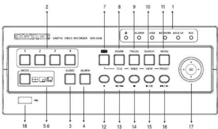
Part Names and Functions
text_image
2 DIGITAL VIDEO RECORDER SHR-240 1 2 3 4 MODE AUDIO ALARM 7 8 9 10 11 1 ALARM HOD NETWORK BACK UP REC ZOOM FREEZS SEARCH MENU TELE WIDE VIEW PRESET 18 5.6 3 4 12 13 14 15 16 17[SHR-2040]
| No. | Name | Function | |||
| 1 | 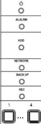 | Power LED | Displays power on/off condition. | ||
| Alarm LED | lights on when an event occurs. | ||||
| HDD Access LED | Displays Normal Access to HDD. Upon Access to HDD, LED repeats on and off. | ||||
| Network LED | Displays both network connection and data transmission conditions. | ||||
| Backup LED | Displays Back Up Mode. | ||||
| Rec LED | Displays the record condition. | ||||
| 2 | Channel Button | Selects a channel in the Single Mode. Used for number input button in the number input mode. | |||
| 3 |  | Audio Setup Button | Sets the Audio On/Off. | ||
| 4 |  | Alarm Setup Button | Cancels the alarm when the Alarm button is selected. | ||
| 5 |  | Split Screen Selection Button | Display Mode | Displays 4 split screen. | |
| Displays PIP(Picture in Picture) screen. | |||||
| The single channel screen is changed according to the time set on the menu. | |||||
| 6 | MODE | Mode Selection Button | Search | Displays 4 split screen. | |
| Displays both LIVE Channel and Playback Channel in the PIP Screen simultaneously. | |||||
| Displays 6 split screen.(1 CH playback screen and 4 CH live screen) | |||||
| Displays 9 split screen.(4 CH playback screen and 4 CH live screen) | |||||
| No. | Name | Function | ||
| 7 |  | PTZ Button | Performs the TELE, WIDE, PRESET, and VIEW function. | |
| 8 |  | ZOOM(TELE) Button | Sets up Digital Zoom(x2). (Performs the TELE function by pressing the PTZ button.) | |
| 9 |  | FREEZE(WIDE) Button | Performs the FREEZE function in the DISPLAY Mode. (Performs the WIDE function by pressing the PTZ button.) | |
| 10 |  | SEARCH(VIEW) Button | Displays the search method. (Performs the VIEW function by pressing the PTZ button.) | |
| 11 |  | MENU (PRESET) Button | Displays the system setup menu or enters to the upper menu.(Performs the PRESET setup function by pressing the PTZ.) | |
| 12 |  | RECORD | Records the record setup set in the normal record mode. | |
| 13 |  | Search Function Key | Fast/Step Reverse | Fast Reverse: Used for the fast rewinding search in the playback mode. Step Reverse: Used for the 1 step reverse search during the pause. |
| 14 |  | STOP | Used for the search stop in the playback mode. | |
| 15 |  | PLAY/PAUSE | Toggles in the playback mode to activate PLAY/PAUSE. | |
| 16 |  | Fast/Step Forward | Fast Forward: Used for the fast-forwarding search in the playback mode. Step Forward: Used for the 1 step-forwarding search during the pause. | |
| 17 | 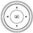 | Direction Button Key | In case of setting the details of Menu, it is used as Direction Key. (For PTZ Operation) | |
| ▲ | In case of setting the details of Menu, it increases the value or it is used as Direction Key. (For PTZ Operation) | |||
| ▶ | In case of setting the details of Menu, it is used as Direction Key. (For PTZ Operation) | |||
| ▼ | In case of setting the details of Menu, it decreases the value or it is used as Direction Key. (For PTZ Operation) | |||
| ◀ | Acts as the Enter key for the menu setup. | |||
| 18 |  | USB Port | Connects the USB type device. | |
text_image
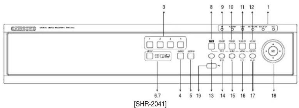
3 8 9 10 11 12 1 1 1 2 3 4 JCOM REELED SWITCH MIND 6.7 4 5 19 13 14 15 16 17 18 [SHR-2041]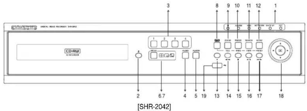
text_image
CD-ROM [SHR-2042] CD-RW CD-ROM 3 8 9 10 11 12 1 1 2 6.7 4 5 19 13 14 15 16 17 18| No. | Name | Function | |||
| 1 | Power LED | Displays power on/off condition. | |||
| ALALRM | Alarm LED | lights on when an event occurs. | |||
| HDD | HDD Access LED | Displays Normal Access to HDD. Upon Access to HDD, LED repeats on and off. | |||
| NETWORK | Network LED | Displays both network connection and data transmission conditions. | |||
| BACK UP | Backup LED | Displays Back Up Mode. | |||
| REC | Rec LED | Displays the record condition. | |||
| 2 | Eject Button | Performs the OPEN/CLOSE of CD/RW. | |||
| 3 | Channel Button | Selects a channel in the Single Mode. Used for number input button in the number input mode. | |||
| 4 | Audio Setup Button | Sets the Audio On/Off. | |||
| 5 | Alarm Setup Button | Turns off the alarm LED and stops the sound when an alarm is issued.Alarm icon disappears when the alarm button is used. | |||
| 6 | Split Screen Selection Button | Display Mode | Displays 4 split screen. | ||
| Displays PIP(Picture in Picture) screen. | |||||
| Auto Sequence Mode: The single channel screen is changed according to the time set on the menu. | |||||
| 7 | MODE | Mode Selection Button | Search | Displays 4 split screen. | |
| Displays the selected channel to the Single Mode | |||||
| Displays both LIVE Channel and Playback Channel in the PIP Screen simultaneously. | |||||
| Displays 6 split screen.(1 CH playback screen and 4 CH live screen) | |||||
| Displays 9 split screen.(4 CH playback screen and 4 CH live screen) | |||||
| 8 |  | PTZ Button | Performs the TELE, WIDE, PRESET, and VIEW function. | ||
| 9 | ZOOM | ZOOM(TELE) Button | Sets up Digital Zoom(x2).(Performs the TELE function by pressing the PTZ button.) | ||
| 10 |   | FREEZE(WIDE) Button | Performs the FREEZE function in the DISPLAY Mode.(Performs the WIDE function by pressing the PTZ button.) | ||
| 11 | VIEW | SEARCH(VIEW) Button | Displays the search method.(Performs the VIEW function by pressing the PTZ button.) | ||
| 12 | [3XX3]PRESET | MENU (PRESET) Button | Displays the system setup menu or enters to the upper menu.(Performs the PRESET setup function by pressing the PTZ.) | ||
| 13 | [DBC3] | RECORD | Records the record setup set in the normal record mode. | ||
| 14 |  | Search Function Key | Fast/Step Reverse | Fast Reverse: Used for the fast rewinding search in the playback mode.Step Reverse: Used for the 1 step reverse search during the pause. | |
| 15 | [7XS3] | STOP | Used for the search stop in the playback mode. | ||
| 16 | [8SYX] | PLAY/PAUSE | Toggles in the playback mode to activate PLAY/PAUSE. | ||
| 17 |  | Fast / Step Forward | Fast Forward: Used for the fast-forwarding search in the playback mode.Step Forward: Used for the 1 step-forwarding search during the pause. | ||
| 18 |  | Direction Button Key | In case of setting the details of Menu, it is used as Direction Key. (For PTZ Operation) | ||
| ▲ | In case of setting the details of Menu, it increases the value or it is used as Direction Key. (For PTZ Operation) | ||||
| ▶ | In case of setting the details of Menu, it is used as Direction Key. (For PTZ Operation) | ||||
| ▼ | In case of setting the details of Menu, it decreases the value or it is used as Direction Key. (For PTZ Operation) | ||||
| Acts as the Enter key for the menu setup. | |||||
| 19 |  | USB Port | Connects the USB type device. | ||

text_image
VIDEO IN THRUOCH RS-332C CH 1 CH 2 CH 3 CH 4 AVISO IN AVISO OUT VIDEO OUT VGA S-VI/VO SPOT OUT NETWORK DC12V 3 4 5 6 7 8 9 10 11 12 13 14 15 16[SHR-2040]
Caution
Do not play DVR on the carpet or other soft material to prevent clogging of the air ventilator. To play DVR on the cabinet or rack, be sure to check the ventilation condition.
| No. | Name | Function |
| 1 | VIDEO IN | Composite Video Signal Input Port (BNC Style Connector) |
| 2 | THROUGH | You may use THROUGH port to transmit a video signal to the other video equipment. |
| 3 | AUDIO IN | Audio Signal Input Port (RCA Jack) |
| 4 | AUDIO OUT | Audio Signal Output Port (RCA Jack) |
| 5 | VIDEO OUT | Composite Video Signal Output Port (BNC Style Connector) |
| 6 | VGA | VGA Video Signal Output Port |
| 7 | S-VIDEO | S-VIDEO Video Signal Output Port |
| 8 | SPOT OUT | SPOT Out Output Port (BNC Style Connector) |
| 9 | ALARM | - ALARM IN 1~4 : Alarm Input Port- ALARM RESET IN : Alarm Reset Port- ALARM OUT1~2 : Alarm Output Port- TX+, TX-, RX+, RX- : RS-485 Communication |
| 10 | USB | USB connection Port |
| 11 | NETWORK | Network Connection Port |
| 12 | DC-IN | 12V Power Socket Support |
text_image
VDDI 80 R-120K ON1 ON2 ON3 ON4 + + + + + + + + + + + + + + + + + + + + + + + + + + + + + + + + + + + + + + + + + + + + + + + + + + + + + + + + + + + + + + + + + + + + + + + + + + + + + + + + + + + + + + + + + + + + + + + + + + + + + + + + + + + + + + + + + + + + + + + + + + + + + + + + + + + + + + + + + + + + + + + + + + + + + + + + + + + + + + + + + + + + + + + + + + + + + + + + - VDDI OUT VMA LABOR UNIT OUT R-120K R-120K R-120K R-120K R-120K R-120K R-120K R-120K R-120K R-120K R-120K R-120K R-120K R-120K R-120K ACIN ③ ⑤ ⑥ ⑦ ⑧ ⑨ ⑪ ⑫ ⑬ ⑭ ⑮ ⑯ ⑰ ⑱ ⑲ ⑳ ⑴ ⑵ ⑶ ⑷ ⑸ ⑹ ⑺ ① ② ③ ④ ⑤ ⑥ ⑦ ⑧ ⑨ ⑩ ⑪ ⑫ ⑬ ⑭ ⑮ ⑯ ⑰ ⑱ ⑲ ⑳ ⑴ ⑤ ⑥ ⑦ ⑧ ⑨ ⑩ ⑪ ⑫ ⑬ ⑭ ⑮ ⑯ ⑰ ⑱ ⑲ ⑳ ⑴ ⑤ ⑥ ⑦ ⑧ ⑨ ⑩ ⑪ ⑫ ⑬ ⑭ ⑮ ⑯ ⑰ ⑱ ⑲ ⑳[SHR-2041/2042]
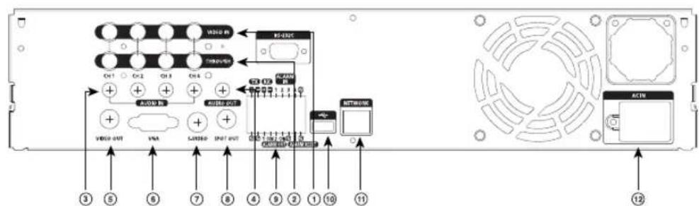
Caution
Do not play DVR on the carpet or other soft material to prevent clogging of the air ventilator. To play DVR on the cabinet or rack, be sure to check the ventilation condition.
| No. | Name | Function |
| 1 | VIDEO IN | Composite Video Signal Input Port (BNC Style Connector) |
| 2 | THROUGH | You may use THROUGH port to transmit a video signal to the other video equipment. |
| 3 | AUDIO IN | Audio Signal Input Port (RCA Jack) |
| 4 | AUDIO OUT | Audio Signal Output Port (RCA Jack) |
| 5 | VIDEO OUT | Composite Video Signal Output Port (BNC Style Connector) |
| 6 | VGA | VGA Video Signal Output Port |
| 7 | S-VIDEO | S-VIDEO Video Signal Output Port |
| 8 | SPOT OUT | SPOT Out Output Port (BNC Style Connector) |
| 9 | ALARM | - ALARM IN 1~4 : Alarm Input Port- ALARM RESET IN : Alarm Reset Port- ALARM OUT1~2 : Alarm Output Port- TX+, TX-, RX+, RX- : RS-485 Communication |
| 10 | USB | USB connection Port |
| 11 | NETWORK | Network Connection Port |
| 12 | AC-IN | (NTSC) AC 110~220V Power Socket Support(PAL) AC 100~230V Power Socket Support |

natural_image
Abstract digital illustration of circuit board patterns and server racks (no text or symbols)Chapter 2 Installation
1 Installation Environment Setup
Do not play DVR on the carpet or other soft material to prevent clogging of the air ventilator. To play DVR on the cabinet or rack, be sure to check the ventilation condition.
You should pay attention to the following before you use the product.
- Do not use it outdoor.
- Do not let water or liquid in the connection part or the product itself.
- Do not impose excessive shock or force.
- Do not pull out the power plug unreasonably.
- Do not disassemble the product on your own.
- Do not exceed the rated input or output range.
- Use certified power cord only.
- Use the power cord with a ground for the product with an input ground.
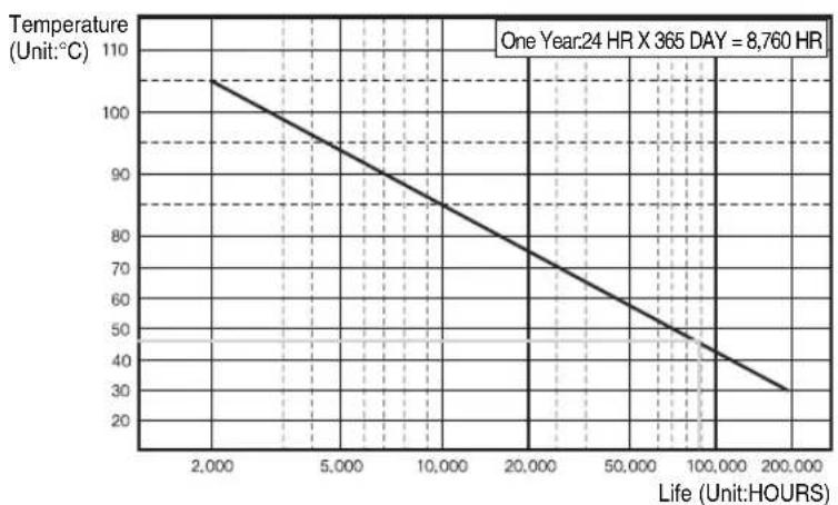
Samsung Digital Video Recorder (hereafter “DVR”) is a high-tech security equipment that contains a high-capacity HDD and top-notch circuits. High temperature inside or outside of the product may cause reduced life and deteriorated performance (see graph 1 below), leading to a malfunction. So please follow the instructions below to proceed with the installation.
line
| Life (Hours) | Temperature (°C) | | ------------ | ---------------- | | 2,000 | 105 | | 5,000 | 95 | | 10,000 | 85 | | 20,000 | 75 | | 50,000 | 65 | | 100,000 | 55 | | 200,000 | 35 |-
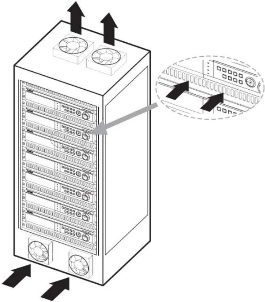
The rack on which the DVR is mounted should not be sealed off.
-
And it also can allow air circulation through the vent.
-
As in the figure to the right, we recommend the product should be stacked up with other DVRs or rack-mounting devices at a certain space or you install a vent system to accommodate airflow.
-
For forming a natural convection, the air intake hole should be positioned at the bottom and the emission at the top.
-
We recommend you install each of the air intake and emission holes with a fan motor for sufficient airflow.
(The air intake fan should be equipped with a filter to block dust and other impurities from inflow.)
- The temperature inside the rack and around the DVR should stay between 0°C and 40°C (32°F and 104°F).
text_image
Diagram of server rack with labeled ports and directional arrows indicating data flow or system movement2
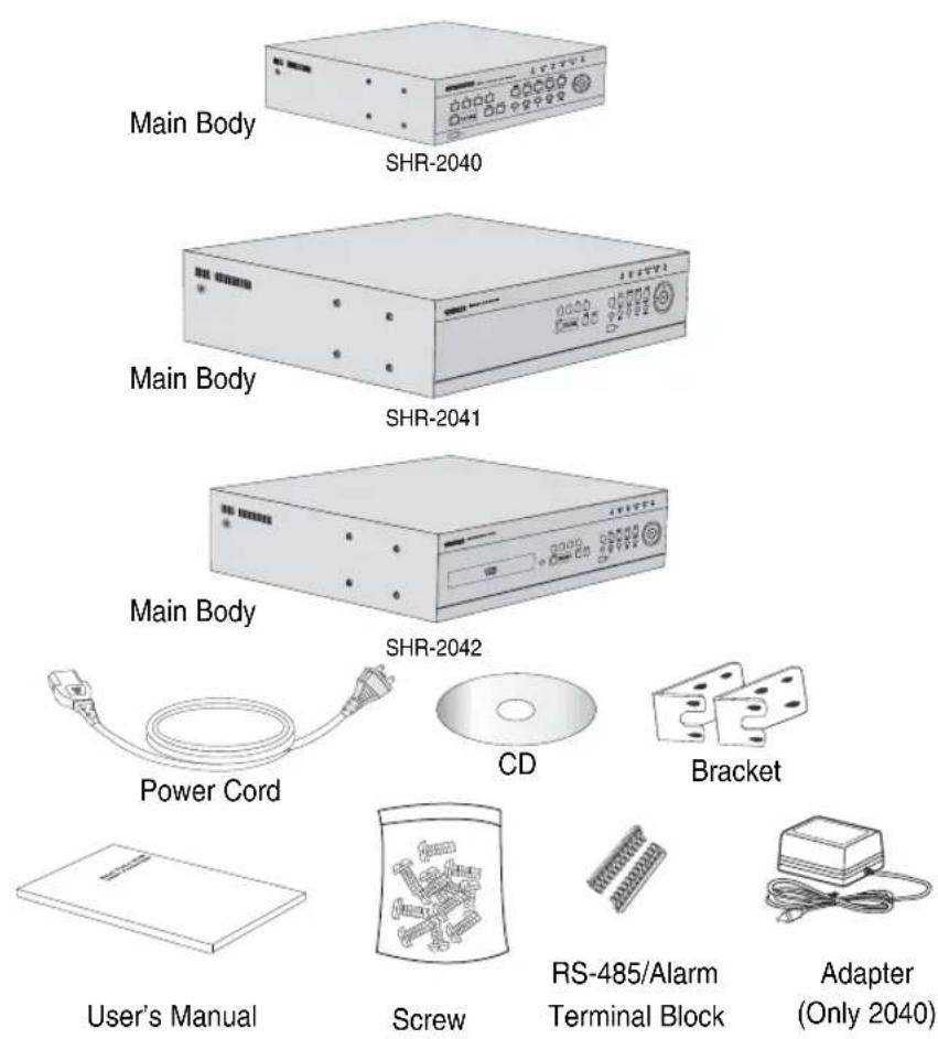
Checking Product & Accessory
Upon delivery of a product, you shall unwrap the product and put it on the even floor or where you want to use it. Then you shall check if the following items are in it.
■ Main Body
■ User's Manual
■ One Power Cord
■ Two Brackets
- These are not supplied in SHR-2040.
- Brackets are used to attach the product to the rack.
■ Smart Viewer Software CD (PDF Manual included)
■ Special Screws
- SHR-2041 : SCREW-SPECIAL 12EA
- SHR-2042 : SCREW-SPECIAL 4EA
- SHR-2040 : SCREW 4EA (Code : 6001-000742)
- Please keep special screws for HDD addition.
■ 2 EA of RS-485/Alarm Terminal Block
3
HDD Addition

Caution
[Checking HDD Data]
Please, pay attention to Following information to minimize the chance of losing HDD data.
- Remember that you should protect HDD from any impact or misuse as this may cause damaged.
- The Manufacturer is not responsible for missing data or defects caused by the user's mishandling.
Note: Adding Extra HDD. Check in advance that the HDD is compatible with the manufacturer's DVR.
Examples that can cause loss of data or damage HDD.
- Any outside Impact on the case which could happen whilst disassembling or setting up the DVR.
- Power cut or incorrect shutdown whilst the DVR is operating.
- Refer to page 5-11: how to turn off DVR
- Moving or causing any impact on the DVR during operation. Please, back up events as soon as possible to minimize disappointment should HDD data be lost.
SHR-2040 HDD ADDITION
The user can add 1 HDD to this product. However, there are many factors that can cause electrical shock, accidents, and malfunctioning of the device inside of the product. When the user does not correctly install or apply the proper settings, the device may not recognize the HDD or the device will not run. Therefore, before adding any HDDs, it is recommended that the user contacts a specialist where they purchased the product.
[Caution when adding a HDD]
- When adding HDDs, pay attention so that the cable doesn't get caught between unsuitable places or the cable's insulation doesn't come off. (This may cause a malfunction or fire.)
■ When adding HDDs, be careful not to receive any injury from the pointed edges inside the product.
■ Pay attention so as not to lose the disassembled screws or accessories. If the screws or accessories are not put together, the product will either malfunction or won't be able to operate.
■ Check the compatibility list of HDDs before installing additional HDDs. The list of the compatible devices with Samsung DVR can be obtained from your vendor.
■ If you contact the RTC battery while adding hard disks, the battery failure may happen. In this case, you will encounter failures when setting the time and operating DVR.
■ If you don't connect fan power cables after adding hard disks, the fan failure message appears on the screen. This can cause operation failures because it raises the temperature inside your DVR.
[Setting the Jumper]
![SAMSUNG SHR-2042P2 - [Setting the Jumper] - 1](/content/2026/06/1189687/images/441f397fb3e100e72e0a7b4634d3de17047c12ae348bfc6950ad91e0e03b0722.jpg)
natural_image
Close-up of a black server rack with a circular button highlighting a specific port (no text or symbols visible)The jumper setting method is illustrated on the surface of the purchased HDD. Using SAMSUNG hard disk, the jumper setting method is as follows:
• HDD jumper for Primary Master and Primary Slave.
![SAMSUNG SHR-2042P2 - [Setting the Jumper] - 2](/content/2026/06/1189687/images/0772331f37080b51b8ec30400c8595ad6bcbf8eb4ea88ab619dea3c42f07fe76.jpg)
![SAMSUNG SHR-2042P2 - [Setting the Jumper] - 3](/content/2026/06/1189687/images/8a563e7a2ea3664710199327a19145faeb679507085035ad31f28f9fd622695c.jpg)
[How to Add a HDD]
- To remove the product's cover, take out the screws on the left and right sides (2 spots each) and on the back (3 spots).
![SAMSUNG SHR-2042P2 - [How to Add a HDD] - 1](/content/2026/06/1189687/images/c63aa8fcf70e8115f50805b15070c4a3afa310eec3809c20f4a4fc4d3169e4c9.jpg)
natural_image
Exterior view of a network switch device with a cable inserted (no visible text or labels)![SAMSUNG SHR-2042P2 - [How to Add a HDD] - 2](/content/2026/06/1189687/images/3edaede18a82ad88b1896babe37dc49cce62c90daee875e43935257e6423b4b3.jpg)
natural_image
Front view of a silver computer drive with ports and a cable inserted, no visible text or symbols- Remove the cover from the product. (Remove the cover by first lifting its back part upward after sliding the cover slightly backward.)
![SAMSUNG SHR-2042P2 - [How to Add a HDD] - 3](/content/2026/06/1189687/images/13be8e4c747fe5296575b5a9351cea6da0e3fc327679ff69b9a3b5eabc82020b.jpg)
natural_image
Exterior view of a computer drive chassis with visible internal components and an arrow indicating motion (no text or symbols)- There is bracket-HDD mounted on the back where you can mount a HDD, and you have to remove the screws (4 spots) that are holding the bracket that you want to mount an HDD onto.
![SAMSUNG SHR-2042P2 - [How to Add a HDD] - 4](/content/2026/06/1189687/images/23fce4ff6f44ad595f43dad5daeb96b0ee7fefbd6f3863cd88ccf6fd32b29e6f.jpg)
text_image
BRACKET-HDD- Remove the bracket-HDD from the product by lifting it upward from the product.
![SAMSUNG SHR-2042P2 - [How to Add a HDD] - 5](/content/2026/06/1189687/images/f925e73fc8b6225e1c7333695911f60a187687e1dc6a10ed457099ae1645b9bb.jpg)
natural_image
Hand placing a component into an open computer case with visible internal wiring and components (no text or symbols)![SAMSUNG SHR-2042P2 - [How to Add a HDD] - 6](/content/2026/06/1189687/images/8e0a9394106ed26b798deb8b321558be3cf6ee855be5956f0f9fc89c9280a092.jpg)
natural_image
Exterior view of a rectangular electronic device with four wheels and a central cutout (no text or symbols visible)- Mount the HDD to the bracket-HDD with the SCREW-TAPTITE (BW, +, S, M3, L6, ZPC) (4 spots) that was provided as an accessory. (The screws have to be tightened so that it doesn't vibrate loose.)
![SAMSUNG SHR-2042P2 - [How to Add a HDD] - 7](/content/2026/06/1189687/images/4ec0159cdb58539b9fa4d8dbbe43dae678caf66b6d64606e396bbb5bc936b1d3.jpg)
natural_image
Exterior view of a white electronic device with ventilation slots and a tool extending from its side (no visible text or symbols)- Re-mount the built-in HDD bracket-HDD to the place where it was separated from. The work order for mounting the BRACKET-HDD is in reverse from when disassembling it. Tighten the screw after the BRACKET-HDD's mounting holes are perfectly aligned with four mounting spots on the bottom.)
![SAMSUNG SHR-2042P2 - [How to Add a HDD] - 8](/content/2026/06/1189687/images/e1073c85865e2e8481399db45c7d87a4c0aa4bc14711e6aa5b999e859513f796.jpg)
natural_image
Interior view of an electronic device showing two modules with visible wiring and components (no readable text or symbols)SCREWDRIVER
- Make sure that the bracket-HDD is mounted stably inside the product, then connect the power supply cable and signal transmission cable (IDE cable) to the HDD.
![SAMSUNG SHR-2042P2 - [How to Add a HDD] - 9](/content/2026/06/1189687/images/a3e2104442767ef1a086d18b3ccfde03cc17d920df40605aad624694dd7a022c.jpg)
natural_image
Interior view of an electronic device housing with visible circuitry and wiring (no readable text or symbols)-
Check if there is any problem with connector or wiring inside of the product for connecting and mounting then close the cover.
-
Tighten cover mounting screws. (The left and right side each has 2 spots and the back side has 3 spots)
SHR-2041 HDD ADDITION
The user can add 3 HDDs to this product.
However, there are many factors that can cause electrical shock, accidents, and malfunctioning of the device inside of the product. When the user does not correctly install or apply the proper settings, the device may not recognize the HDD or the device will not run. Therefore, before adding any HDDs, it is recommended that the user contacts a specialist where you purchased the product.
[Caution when adding a HDD]
■ When adding HDDs, pay attention so that the cable doesn't get caught between unsuitable places or the cable's insulation doesn't come off. (This may cause a malfunction or fire.)
■ When adding HDDs, be careful not to receive any injury from the pointed edges inside the product.
■ Pay attention so as not to lose the disassembled screws or accessories. If the screws or accessories are not put together, the product will either malfunction or will be inoperable.
■ Check the compatibility list of HDDs before installing additional HDDs. The list of the compatible devices with Samsung DVR can be obtained from your vendor.
■ If you contact the RTC battery while adding hard disks, the battery failure may happen. In this case, you will encounter failures when setting the time and operating DVR.
If you don't connect fan power cables after adding hard disks, the fan failure message appears on the screen. This can cause operation failures because it raises the temperature inside your DVR.
[Setting the Jumper]
![SAMSUNG SHR-2042P2 - [Setting the Jumper] - 1](/content/2026/06/1189687/images/7b0b04cc9f14c9f4606eabbbffdad3198dedcb987dd6d85f7b7868dd71f1fc40.jpg)
natural_image
Close-up of a black electronic device with a circular button and arrow pointing to its left side (no text or symbols visible)The jumper setting method is illustrated on the surface of the purchased HDD. Using SAMSUNG hard disk, the jumper setting method is as follows:
• HDD jumper for Primary Master and Primary Slave.
![SAMSUNG SHR-2042P2 - [Setting the Jumper] - 2](/content/2026/06/1189687/images/b62f12f6af0608f7d955873a36bfce540b62823948f30ebf2b38cdc1b1be3cba.jpg)
![SAMSUNG SHR-2042P2 - [Setting the Jumper] - 3](/content/2026/06/1189687/images/bf747834be5e1fff906a380863840267d05a542a64a12cb2e71a7315b36273e5.jpg)
- Jumper setting for Secondary Master and Secondary Slave.
![SAMSUNG SHR-2042P2 - [Setting the Jumper] - 4](/content/2026/06/1189687/images/71da56aef286fdeaf650f62f660e52cc480608c9b94f5db98151397ef8c22504.jpg)
![SAMSUNG SHR-2042P2 - [Setting the Jumper] - 5](/content/2026/06/1189687/images/5b454ed1fdfba7fa70dee5b2c310c3a3eb19588b54c132112bad284bc8bb3624.jpg)
[How to Add a HDD]
- To remove the product's cover, take out the screws on the left and right sides (5 spots each) and on the back (1 spot).
![SAMSUNG SHR-2042P2 - [How to Add a HDD] - 1](/content/2026/06/1189687/images/8468aabbb29fd2ea8056f68cc67c4dccb0b1a9799cfe1ad795870d37b3a39df8.jpg)
natural_image
Exterior view of a silver audio amplifier device with control panel and speaker grille (no visible text or symbols)![SAMSUNG SHR-2042P2 - [How to Add a HDD] - 2](/content/2026/06/1189687/images/011db50f43fd0d445d1b8ab3a49de3548087dd451b48901b965371d05b6c8674.jpg)
natural_image
Front view of a beige computer drive unit with ventilation fans and buttons (no visible text or labels)- Remove the cover from the product. (Remove the cover by first lifting its back part upward after sliding the cover slightly backward.)
![SAMSUNG SHR-2042P2 - [How to Add a HDD] - 3](/content/2026/06/1189687/images/68ec8115384670d56d77987030184cfc393f7297e6132e2fcd9356dc8e30cbd7.jpg)
natural_image
Exterior view of a silver computer drive unit with ventilation fan and control buttons (no visible text or symbols)- There is a bracket (bracket-HDD) mounted on the right and left sides where you can mount the HDD, and you have to remove the screws that are holding the bracket that you want to mount an HDD onto.
![SAMSUNG SHR-2042P2 - [How to Add a HDD] - 4](/content/2026/06/1189687/images/0e22e82ca3a49a1091eff6d565c732a5556452d451fb7e38fc657b12fb669909.jpg)
text_image
BRACKET-HDDSCREWDRIVER SCREWDRIVER
![SAMSUNG SHR-2042P2 - [How to Add a HDD] - 5](/content/2026/06/1189687/images/d30a8f8ebea706b1e674efc65bc7554c4ff22ca087943c38dd33ef8967b5ac4d.jpg)
natural_image
Interior view of a mechanical assembly with mounting holes and wiring (no visible text or symbols)![SAMSUNG SHR-2042P2 - [How to Add a HDD] - 6](/content/2026/06/1189687/images/3ac5e929c9d97558122dedb0ac4b126f578a2639189cfe794ddf58f4eace9eaa.jpg)
natural_image
Interior view of a computer drive bay with visible CPU socket, power connector, and cable (no text or symbols)- Remove the bracket-HDD from the product by separating the power supply cable, signal transmission cable (IDE cable), and fan cable then pulling it toward the center of the product to separate its fixed part from the bottom.
![SAMSUNG SHR-2042P2 - [How to Add a HDD] - 7](/content/2026/06/1189687/images/86388b572bac3eaf536cd36ef39798d53dde93f8161d73fca80379bbec0ec672.jpg)
natural_image
Interior view of an electronic device showing a circuit board with a gray arrow indicating direction (no text or symbols visible)![SAMSUNG SHR-2042P2 - [How to Add a HDD] - 8](/content/2026/06/1189687/images/f04b3dd095578a2a5019f793b71461e1590b0afd888cf3474ba18dc04feac7b6.jpg)
natural_image
Metal bracket with mounting holes and cutouts, no visible text or symbols![SAMSUNG SHR-2042P2 - [How to Add a HDD] - 9](/content/2026/06/1189687/images/0bf69e972b6a4cc56dcd0ab307fa43176cbb5793d9bdf1bcbc534220c2f9a7f7.jpg)
text_image
Black-and-white photo of an open computer case with a printed label showing a barcode and arrow pointing to it.![SAMSUNG SHR-2042P2 - [How to Add a HDD] - 10](/content/2026/06/1189687/images/b40ed7c54457c00e9dfce67845b02b6c475270f791c7ff57a646037e3157c910.jpg)
natural_image
Exterior view of a mechanical power supply unit with fan and motor (no visible text or symbols)- Mount the HDD to the bracket-HDD with the SCREW-SPECIAL (BWH, 6-32UNC, L10.5) (4 spots) that was provided as an accessory. (The screws have to be tightened so that it doesn't vibrate loose.)
![SAMSUNG SHR-2042P2 - [How to Add a HDD] - 11](/content/2026/06/1189687/images/9454b3aed3af280de7bfd3914b13a36472c78a1f405d9649154a92ef52f55130.jpg)
natural_image
Close-up of a mechanical device with a cable inserted, showing internal components and no visible text or symbols.![SAMSUNG SHR-2042P2 - [How to Add a HDD] - 12](/content/2026/06/1189687/images/7363240a57aa5bd882f4f670500fbf6b61f4a551055257ee88fd3e743b51b747.jpg)
natural_image
Black-and-white photo of a computer hard drive with visible fan and cooling unit (no text or symbols)- Re-mount the built-in HDD bracket-HDD to the place where it was separated from. Place the bracket-HDD so that all five mounting spots on the bottom and the bracket-HDD's mounting holes are perfectly aligned, then slide it toward the outside of the product and tigh ten the screws.
![SAMSUNG SHR-2042P2 - [How to Add a HDD] - 13](/content/2026/06/1189687/images/122b23d9d9f2a33ddf9f19e6fffbb1c78f30526f8b29f0cb98719c9a3ab76e67.jpg)
natural_image
Internal view of a hard disk drive with visible internal components and mounting hardware (no text or symbols)![SAMSUNG SHR-2042P2 - [How to Add a HDD] - 14](/content/2026/06/1189687/images/fa19c8b8bbb88386fd99ac7cb5147c04c125d8344cf4325167d82cd4e1ea8f46.jpg)
natural_image
Interior view of an open hard drive showing internal components and cable (no visible text or labels)- Make sure that the bracket-HDD is mounted stably inside of the product, then connect the power supply cable, signal transmission cable (IDE cable), and fan cable to the HDD.
![SAMSUNG SHR-2042P2 - [How to Add a HDD] - 15](/content/2026/06/1189687/images/941150d4436884d90474a47fb6a706ef36e13bb707d55302397c854d9203882b.jpg)
text_image
MASTER HDD SLAVE HDD-
Check if there is any problem with connector or wiring inside of the product for connecting and mounting then close the cover.
-
Tighten cover mounting screws. (The left and right side each has 5 spots and the back side has 1 spot)
Caution
When mounting an additional HDD, the primary master has to be mounted.
SHR-2042 HDD ADDITION
The user can add up to 2 HDDs to this product.
However, there are many factors that can cause electrical shock, accidents, and malfunctioning of the device inside of the product. When the user does not correctly install or apply the proper settings, the device may not recognize the HDD or the device will not run. Therefore, before adding any HDDs, it is recommended that the user contacts a specialist where they purchased the product.
[Caution when adding a HDD]
- When adding HDDs, pay attention so that the cable doesn't get caught between unsuitable places or the cable's insulation doesn't come off. (This may cause a malfunction or fire.)
■ When adding HDDs, be careful not to receive any injury from the pointed edges inside the product.
■ Pay attention so as not to lose the disassembled screws or accessories. If the screws or accessories are not put together, the product will either malfunction or will be inoperable.
■ Check the compatibility list of HDDs before installing additional HDDs. The list of the compatible devices with Samsung DVR can be obtained from your vendor.
■ If you contact the RTC battery while adding hard disks, the battery failure may happen. In this case, you will encounter failures when setting the time and operating DVR.
If you don't connect fan power cables after adding hard disks, the fan failure message appears on the screen. This can cause operation failures because it raises the temperature inside your DVR.
[Setting the Jumper]
![SAMSUNG SHR-2042P2 - [Setting the Jumper] - 1](/content/2026/06/1189687/images/247a1be4fb11b0f7cc89db8464fd65d65590899b5441db34229e0d736c9fe98e.jpg)
natural_image
Close-up of a black server rack with a circular button highlighting a grid of pins (no text or symbols visible)The jumper setting method is illustrated on the surface of the purchased HDD. Using SAMSUNG hard disk, the jumper setting method is as follows:
• HDD jumper for Primary Master and Primary Slave.
![SAMSUNG SHR-2042P2 - [Setting the Jumper] - 2](/content/2026/06/1189687/images/cc1ff3d835d62183135bb6eefc1ad977ab26bb7829a6d3abd77e573b4c58047a.jpg)
![SAMSUNG SHR-2042P2 - [Setting the Jumper] - 3](/content/2026/06/1189687/images/6582d9c77ee0b42a900f75e87d4b6636fe952ff216a91e5931b5bc08e6766184.jpg)
- Jumper setting for Secondary Master (CD-RW) and Secondary Slave.
![SAMSUNG SHR-2042P2 - [Setting the Jumper] - 4](/content/2026/06/1189687/images/78ac404c420e435f8e3e4047c7a62271054b0dec52f40618114209c143c29542.jpg)
![SAMSUNG SHR-2042P2 - [Setting the Jumper] - 5](/content/2026/06/1189687/images/1f13f19586e00f4d00936a6a4bc588a1125be51b8840acd85068e83365f60bf0.jpg)
[How to Add a HDD]
- To remove the product's cover, take out the screws on the left and right sides (5 spots each) and on the back (1 spot).
![SAMSUNG SHR-2042P2 - [How to Add a HDD] - 1](/content/2026/06/1189687/images/3f2f4f9214b3d7eaa835a719bf0579ebab37b8d43ab3210b5fdd4eacf4c31a3c.jpg)
natural_image
Exterior view of a silver audio device with control panel and speaker grille (no visible text or symbols)![SAMSUNG SHR-2042P2 - [How to Add a HDD] - 2](/content/2026/06/1189687/images/93f03b424b0c6ff3726547ca4b47f1ebbcea28878f69a997c258e5c91280ff8f.jpg)
natural_image
Front view of a silver computer drive unit with ventilation fans and drive spout (no visible text or labels)- Remove the cover from the product. (Remove the cover by first lifting its back part upward after sliding the cover slightly backward.)
![SAMSUNG SHR-2042P2 - [How to Add a HDD] - 3](/content/2026/06/1189687/images/c6543c44c9e0a3ed20f01d050da7e6b7310894e17fc05e069afb8732675cd188.jpg)
natural_image
Exterior view of a silver computer drive unit (no visible text or symbols)- There is a bracket (bracket-HDD) mounted on the right and left sides where you can mount the HDD, and you have to remove the screws that are holding the bracket that you want to mount an HDD onto.
![SAMSUNG SHR-2042P2 - [How to Add a HDD] - 4](/content/2026/06/1189687/images/7643b27490efc05b862135e68be03818596c4a82e1e561ac42c8dc6ecf179c7c.jpg)
text_image
BRACKET-HDD(A) BRACKET-HDD(B)SCREWDRIVER SCREWDRIVER
![SAMSUNG SHR-2042P2 - [How to Add a HDD] - 5](/content/2026/06/1189687/images/695f82916c101bf7c47eded6c591314f993f67efc1cad6a6d98ef108c9e51f00.jpg)
natural_image
Interior view of a computer drive bay with visible internal components and a label (no readable text or symbols)![SAMSUNG SHR-2042P2 - [How to Add a HDD] - 6](/content/2026/06/1189687/images/7305dbdb83540e11c8851e766febde5974625ea4384cef91745c289c97a1d5a2.jpg)
natural_image
Close-up of a white electronic device with ventilation grilles and mounting hardware (no visible text or symbols)- Remove the bracket-HDD (A) from the product by disconnecting the power supply cable, signal transmission cable (IDE cable), and fan cable then pulling it toward the center of the product to disconnect its fixed part from the bottom. Remove the bracket-HDD (B) by lifting it up after removing the screws.
![SAMSUNG SHR-2042P2 - [How to Add a HDD] - 7](/content/2026/06/1189687/images/c8af06b85cbe6a9f9bdb62b9f1c6a885b4351f77a6773cef85a2972de85ab87e.jpg)
natural_image
Interior view of a computer drive bay with visible internal components and cable (no readable text or symbols)![SAMSUNG SHR-2042P2 - [How to Add a HDD] - 8](/content/2026/06/1189687/images/a23afb389c2453acad5021f377dccc9158ea87fb2128787e3f1fe2ff46fbfd88.jpg)
natural_image
Close-up of a white rectangular electronic device with ventilation grilles and mounting points (no visible text or symbols)![SAMSUNG SHR-2042P2 - [How to Add a HDD] - 9](/content/2026/06/1189687/images/36b8f8f09b5e0af98c49ad054185c6219d46eca3f270a5c1ea28b8f9bc62cd61.jpg)
natural_image
Exterior view of a hard drive chassis with visible battery pack and mounting brackets (no text or symbols)![SAMSUNG SHR-2042P2 - [How to Add a HDD] - 10](/content/2026/06/1189687/images/b337cfae1a485273aa2a83a358845963a44d5d66af0119f4dc3455d9d5058bb5.jpg)
natural_image
Exterior view of a white plastic enclosure with ventilation slots and two wheels (no text or symbols visible)- Mount the HDD to the bracket-HDD with the (A)SCREW-SPECIAL (BWH,6-32UNC,L10.5) and (B)SCREW-TAPTITE (BH,+,S,M3,L6,ZPC) (4 spots) that was provided as an accessory. (The screws have to be tightened so that it doesn't vibrate loose.)
![SAMSUNG SHR-2042P2 - [How to Add a HDD] - 11](/content/2026/06/1189687/images/c2e0327f95d7adb2476d5243d0e727b336a62e8452be1896a7aa97a4332ce440.jpg)
natural_image
Close-up of an electronic device with a metal screw and cable inserted, no visible text or symbols on the body.![SAMSUNG SHR-2042P2 - [How to Add a HDD] - 12](/content/2026/06/1189687/images/685cddc2c4f60705e50c3e2024424ee51a74c4382c8c97949310fec8e9e1da51.jpg)
natural_image
Exterior view of a white electronic device with ventilation slots and a tool extending from its side (no visible text or symbols)- Re-mount the built-in HDD bracket-HDD to the place where it was removed from. Place the bracket-HDD(A) so that all the five fixing areas in the bottom and the bracket-HDD's fixing holes can perfectly aligned, then slide it outward of the product and tighten the screws. For the bracket-HDD (B), place it so that all the four fixed areas at the bottom and the bracket-HDD's fixed holes can perfectly aligned, then tighten the screws.)
![SAMSUNG SHR-2042P2 - [How to Add a HDD] - 13](/content/2026/06/1189687/images/5cd77fde71e9feb86c337da6acf588f14220a6e418f4ca7c13e257866595f558.jpg)
natural_image
Interior view of a computer hard drive showing internal components and cable (no visible text or labels)![SAMSUNG SHR-2042P2 - [How to Add a HDD] - 14](/content/2026/06/1189687/images/b879a031166c9b88e2d4cc2276ee98b81c66484b50f8e5b044600e2d506c0907.jpg)
text_image
Black-and-white photo of an electrical control box with visible label and wiring, showing Chinese text and symbols.- Make sure that the bracket-HDD is mounted stably inside of the product, then connect the power supply cable and signal transmission cable (IDE cable) to the HDD.
![SAMSUNG SHR-2042P2 - [How to Add a HDD] - 15](/content/2026/06/1189687/images/07c81b2e95d65f7299fe32ddfbb44869eb419158087d0fb915aff3d1b28a9f49.jpg)
text_image
MASTER HDD SLAVE HDD-
Check if there is any problem with connector or wiring inside of the product for connecting and mounting then close the cover.
-
Tighten cover mounting screws. (The left and right side each has 5 spots and back side has 1 spot)
![SAMSUNG SHR-2042P2 - [How to Add a HDD] - 16](/content/2026/06/1189687/images/cd03fd4e95a2eea472e4ee6c10f5816639e50791c2f237f796e84c003bf8a83f.jpg)
Caution
When mounting an additional HDD, the primary master has to be mounted.
The HDD has to be set as the primary master, and the CD-RW has to be set as the secondary master.
When adding a HDD, please add the same kind of HDD that you used for this product.
For HDD addition, please select the same HDD with the existing HDD fixed to the product as far as possible.
- Jumper settings when mounting 2 SHR-2040 HDDs
Due to the limited space, set the jumper for both HDDs to the master mode for the SHR-2040.
→ 1st HDD : Master mode (Primary IDE Cable),
2nd HDD : Master mode (Secondary IDE Cable)
- Extra precaution is necessary for the SHR-2042. The built-in CD-RW is set up as the secondary mater.
→ 1st HDD : Master mode (Primary IDE Cable),
2nd HDD : Slave mode (Primary IDE Cable),
3rd HDD : Slave Mode (Secondary IDE Cable) The internal CD-RW is connected to the secondary master.) respectively
Both HDDs attached to Primary Slot and Secondary Slot should be set to Master and Slave respectively. Refer to User's Manual for Master or Slave Jumper Setting.
In the event of only one HDD installation, it shall be inserted into the Primary slot.
WARNING
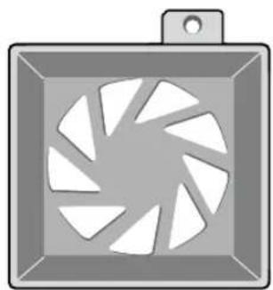
① Regarding the sub fan, you need additional brackets and sub fans as follows.
The sub fan is shaped like this when viewed from the front and back. Please pay attention to the fan direction to let wind go through the fan.
natural_image
Illustration of a camera fan with blades, no text or symbols present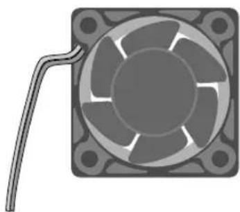
natural_image
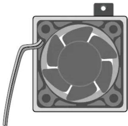
Illustration of a square fan with internal blades and a curved cable extending from its side (no text or symbols)② Fix the fan as follows
natural_image
Illustration of a square fan with internal blades and a coiled cable attached (no text or symbols)③ Please install the fan which is seen at the right from the front view of SHR-set as follows.

natural_image
Technical illustration of a mechanical assembly with three views showing internal components and a tool inserted into a fan (no text or symbols present)④ The cable should be out from the left hole.

natural_image
Top-down schematic of a computer motherboard showing CPU socket, drive fan, and circuit board (no text or labels)
natural_image
Abstract digital illustration of circuit board patterns and server racks (no text or symbols)Chapter 3 Connecting with other device
1
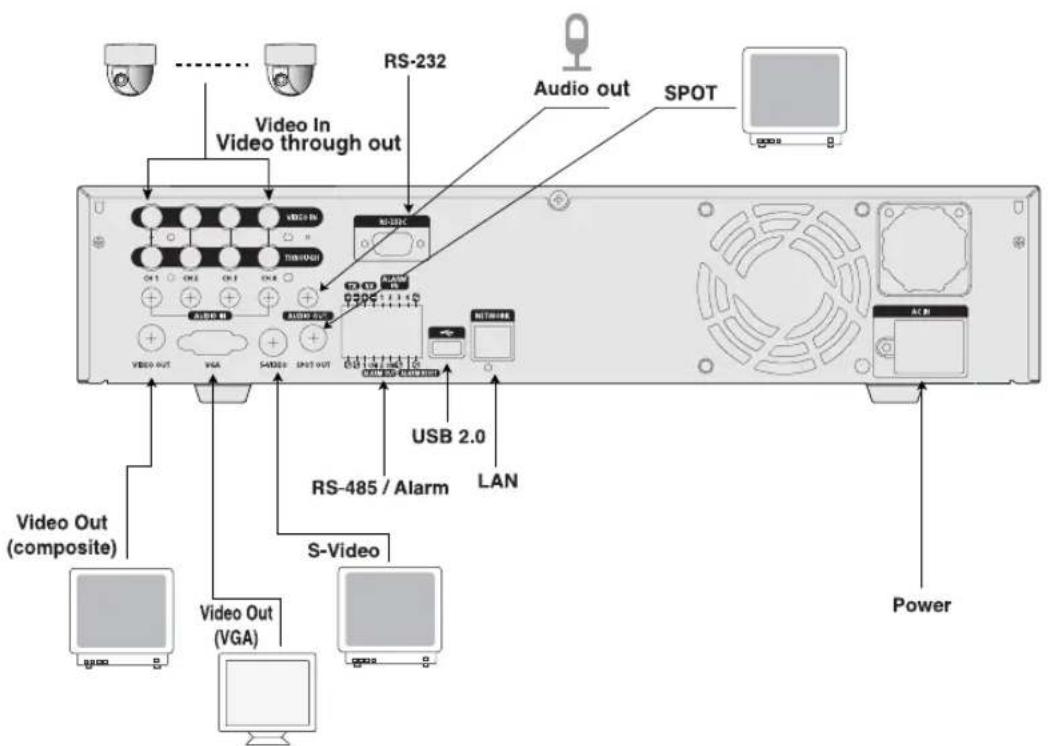
Connecting the Video, Audio, and Monitor

text_image
Audio in Video through out RS-232 Audio out SPOT VIAO IN TRIWO/1 AVIO IN AUDIO OUT VIAO OUT VGA S-VIDEO SPOT OUT USB 2.0 LAN RS-485 / Alarm S-Video Video Out (composite) Video Out (VGA) UPCOM DC12V[SHR-2040]
text_image
Video In Video through out RS-232 Audio out SPOT USB 2.0 RS-485 / Alarm LAN S-Video Video Out (composite) Video Out (VGA) Power[SHR-2041/2042]
2
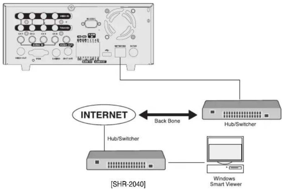
Connecting the Network
- Connecting to Internet through Ethernet(10/100BaseT)
flowchart
graph TD
    A["Internet"] -->|Back Bone| B["Hub/Switcher"]
    B --> C["Windows Smart Viewer"]
    A <--> D["Shr-2040"]
- Connecting to Internet through ADSL

flowchart
graph TD
    A["Device 1"] --> B["Internet"]
    C["Device 2"] --> B
    D["Device 3"] --> B
    E["Device 4"] --> B
    F["Device 5"] --> B
    G["Device 6"] --> B
    H["Device 7"] --> B
    I["Device 8"] --> B
    J["Device 9"] --> B
    K["Device 10"] --> B
    L["Device 11"] --> B
    M["Device 12"] --> B
    N["Device 13"] --> B
    O["Device 14"] --> B
    P["Device 15"] --> B
    Q["Device 16"] --> B
    R["Device 17"] --> B
    S["Device 18"] --> B
    T["Device 19"] --> B
    U["Device 20"] --> B
    V["Device 21"] --> B
    W["Device 22"] --> B
    X["Device 23"] --> B
    Y["Device 24"] --> B
    Z["Device 25"] --> B
    AA["Device 26"] --> B
    AB["Device 27"] --> B
    AC["Device 28"] --> B
    AD["Device 29"] --> B
    AE["Device 30"] --> B
    AF["Device 31"] --> B
    AG["Device 32"] --> B
    AH["Device 33"] --> B
    AI["Device 34"] --> B
    AJ["Device 35"] --> B
    AK["Device 36"] --> B
    AL["Device 37"] --> B
    AM["Device 38"] --> B
    AN["Device 39"] --> B
    AO["Device 40"] --> B
    AP["RJ45 Ethernet Cable (Direct Cable)"] --> AQ["Phone(ADSL) Line"]
    AQ --> AR["ADSL MODEM"]
    AR --> AS["SHR-2040"]
    AT["Windows Smart Viewer"] --> AU["Computer"]
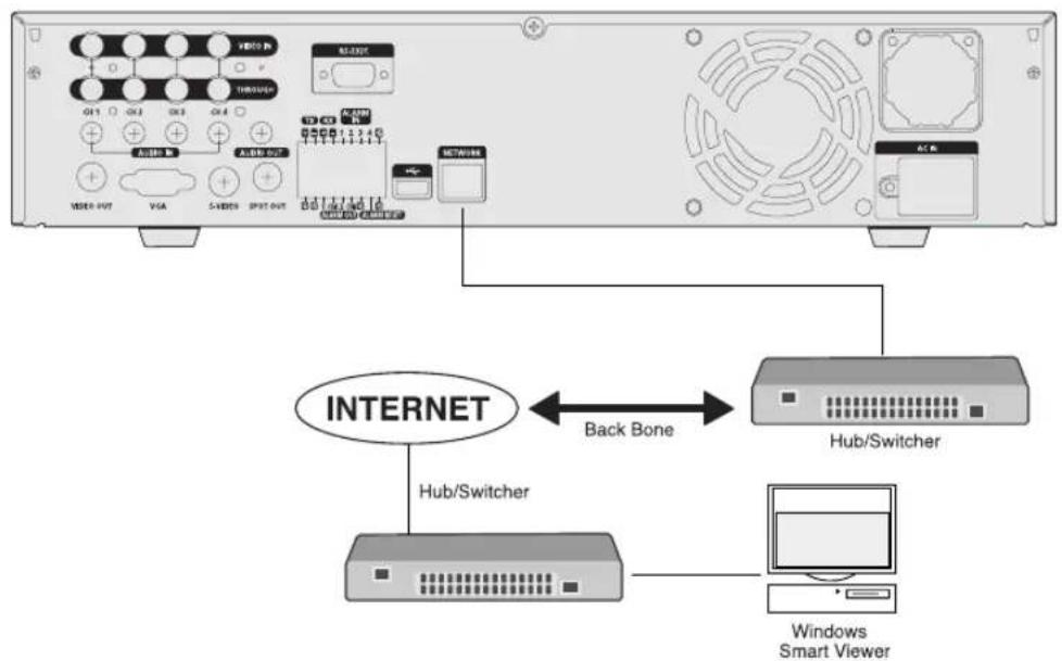
- Connecting to Internet through Ethernet(10/100BaseT)
flowchart
graph TD
    A["Front Panel"] --> B["BackBone"]
    B --> C["Hub/Switcher"]
    C --> D["Windows Smart Viewer"]
    A --> E["Internet"]
    E --> F["Hub/Switcher"]
    F --> G["Windows Smart Viewer"]
[SHR-2041/2042]
● Connecting to Internet through ADSL
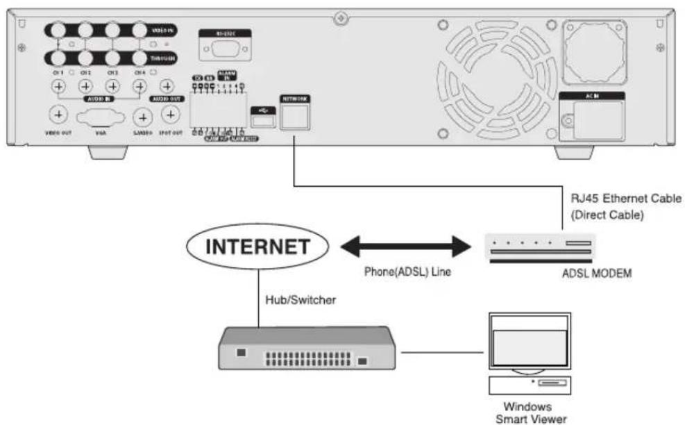
text_image
VDD-15 TIMI-12/18 CN 1 CN 2 CN 3 CN 4 + + + + + + + + + + + + + + + + + + + + + + + + + + + + + + + + + + + + + + + + + + + + + + + + + + + + + + + + + + + + + + + + + + + + + + + + + + + + + + + + + + + + + + + + + + + + + + + + + + + + + + RJ45 Ethernet Cable (Direct Cable) INTERNET Hub/Switcher Phone(ADSL) Line ADSL MODEM Windows Smart Viewer[SHR-2041/2042]
3c
Connecting the USB
-
There are two USB connecting ports on the front and back of SHR-2040/2041/2042.
-
USB Hard Disk, USB CD/DVD, and USB Memory are connected through the front and back ports of SHR-2040/2041/2042.
-
Only one USB device can be connected with each USB connecting port.
-
If the USB HDD is connected to the system, it should be detected and set through Menu - System - HDD setup before the operation.
-
It supplies the function of HOT PLUG, which connects/removes the USB device, during the system operation.
Note
See 5-8 System (HDD Setup) of User's Manual.

Caution
- USB port on the front and back of SHR-2040/2041/2042 cannot be connected to same kinds of USB device. (For example, the case is that 2 CD-RW devices or 2 USB Memories are used by connection with the front and back of system.)
- If you use the USB Memory on SHR-2040/2041/2042, it should be composed of the format being supported by SHR-2040/2041/2042. Although you format it with FAT32 format on PC, it will be re-formatted, in case of (when) connecting with SHR-2040/2041/2042.

Caution
- The hard disk of USB device should be set to Master.
4
Connecting the Alarm Input/Output
The Alarm IN/OUT port in the back of SHR-2040/2041/2042 is composed of the following elements.

text_image
TX RX ALARM IN + - + - 1 2 3 4 G - - - - - - - G G 1 COM 2 COM G G ALARM OUT ALARM RESET● ALARM IN/OUT Connection
| Name Function | ||
| 1 - ALARM IN2- ALARM IN3- ALARM IN4 | - ALARM IN1 | ALARM Input Port |
| 2 - ALARM RESET IN | - ALARM RESET IN | On receiving an ALARM RESET signal, the system cancels the current ALARM input and output signal and then resumes sensing. |
| 3 - ALARM OUT1- ALARM OUT2 | - ALARM OUT1 | ALARM Output Port |
● ALARM IN/OUT Connection
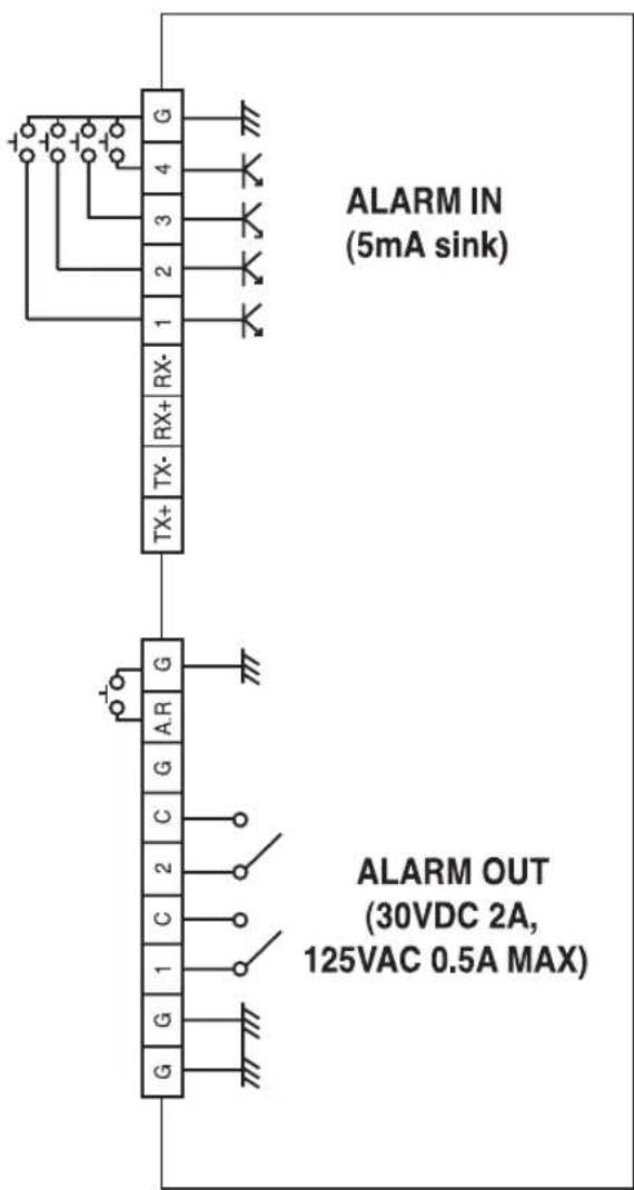
text_image
ALARM IN (5mA sink) ALARM OUT (30VDC 2A, 125VAC 0.5A MAX)5.
Connecting the RS-485 Device
- Connect the RS-485 Device through the back port of SHR- SHR-2040/2041/2042.
● You can install and control the PTZ camera supporting the RS-485 communication.

text_image
TX RX ALARM IN + - + - 1 2 3 4 G G G 1 COM 2 CCM G G ALARM OUT ALARM RESET- You can adopt either Half Duplex or Full Duplex method for the connection.
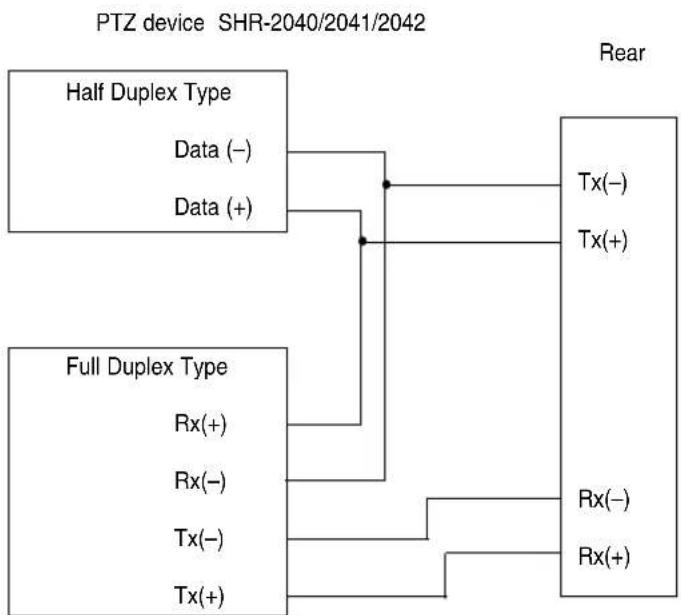
flowchart
graph TD
    A["PTZ device SHR-2040/2041/2042"] --> B["Half Duplex Type"]
    B --> C["Data (-)"]
    B --> D["Data (+)"]
    E["Full Duplex Type"] --> F["Rx(+)"]
    E --> G["Rx(-)"]
    E --> H["Tx(-)"]
    E --> I["Tx(+)"]
    J["Rear"] --> K["Tx(-)"]
    J --> L["Tx(+)"]
    M["Rear"] --> N["Rx(-)"]
    M --> O["Rx(+)"]
● Baud Rate supports 600 / 1200 / 2400 / 4800 / 9600 / 19200 / 38400.

Caution
Check if RS-485 device is compatible with SHR-2040/2041/2042 first. Then pay attention not to change the polarity(+,-) of RS-485 when connecting it.

natural_image
Abstract digital illustration of a server room with circuit board, laptop, and server racks (no text or symbols)Chapter 4 Live
1 System Operation
● Turn the power on and the following LOGO pops up on the screen.

text_image
SAMSUNG DIGITAL everyone's invited_- After the LOGO appears, all of LED in the front flickers 6 times to initialize the system for operation.
- Upon completion of normal initialization, the Live screen appears accompanying a beep sound.
- It requires 30 to 40 seconds until the Live screen appears.
Note
If a new HDD is installed, it may require more time to be appeared the Live screen due to the initialization time of a new HDD.
If the Live screen does not appear continuously or the LED in front repeats flickering, please check the connection between inside and outside. If the system does not operate in normal, contact with the shop where you bought the product.
● The Live screen does not affect the earlier MENU setup. If you reboot the system after power-off during recording, the Live screen will appear, accompanying recording.
Note
If the Live screen dose not appear, check if the Video Out comes out in Composite mode or VGA mode.
2
Live Screen Mode
Definition of Live Screen Icon
The Live screen icons display the current setup and function status of each screen.
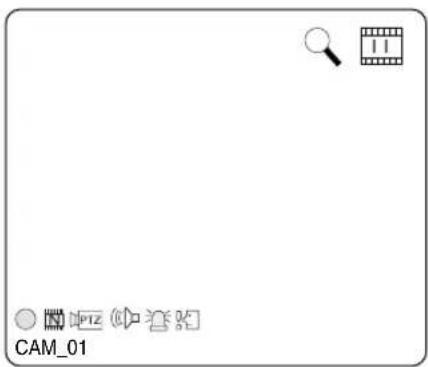
text_image
CAM_01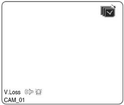
text_image
V.Loss CAM_01○/E/S: Recording Icon
Each icon represents Normal / Event (Alarm + Motion) / Schedule Recording.
L/N/C: Recording Video Size Icon
Each icon represents the recording size of Large / Normal / CIF.
- Large : Full D1 - (NTSC) 720X480 (PAL) 720X576
- Normal : Half D1 - (NTSC) 720X240 (PAL) 720X288
- CIF : CIF - (NTSC) 352X240 (PAL) 352X288
(Full D1 is supported only when "1 CH DVR support")
: Recording lock icon
It indicates record lock while in record setup.
This icon appears while recording with the recording lock set.
You have to enter a password to cancel the recording.
PTZ / PTZ : PTZ Icon
This icon appears when setting the PTZ device with the PTZ icon and changes to yellow color when operating the PTZ.
Audio Icon
This icon represents the Audio On/Off status and changes to yellow color at the Audio On. It does not appear in the Video mode or Audio Disable.
: Sensor In Event Icon
This icon appears in the channel linked with the external sensor signal when inputting the signal at the Sensor On.
: Motion Event Icon
This icon appears in the Motion Event channel at the Motion Detection On.
: Zoom Icon
This icon appears at the Zoom On or Zoom In and disappears when canceling the Zoom On.
: Freeze Icon
This icon appears in the Freeze mode and disappears when canceling the Freeze.
: HDD Recording Disk Full Icon
This icon appears when the recording space is full in the HDD.
: Auto sequence Icon
This icon appears in the auto sequence mode.
: Backup Playback Icon
This icon appears when the backup data is played.
: Fan Error Icon
This icon appears when the fan stops.
: No HDD icon
This icon appears when there is a dysfunctional hard disk.
V.Loss / V.Off : Video Input Status
If there is no more video data input in the Video On, [V.Loss] appears in the channel.
If you set Video On/Off to Off, [V.Off] will appear.
Definition of Live Screen Mode
The system receives 3 live images and displays them in the following 3 modes.

flowchart
graph LR
    A["CAM_01"] --> B["CAM_02"]
    C["CAM_03"] --> D["CAM_04"]
    B --> E["CAM_01"]
    D --> E
    E --> F["Output Box"]
4 Split Mode
PIP Mode Auto sequence Mode
- 4 Split Mode:
Four channels are split in the screen separately.
You are able to choose a channel as you want to in each split mode.
● PIP(Picture In Picture) Mode:
Displays a one-fourth sized screen in the full screen. You are able to choose a channel as you want to, which is displayed in the full screen and reduced screen area. You may move the PIP screen at 5 stages in the Full screen with the ▲,▼ key.
● Auto sequence Mode:
Displays the full screen of each channel in sequence according to the setup time.
Selecting Live Screen Mode
Each mode may be selected by [MODE Button] and [CH1 \~ CH4 Button]. The following figure shows Live Mode after converted.
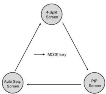
flowchart
graph TD
    A["4-Split Screen"] -->|MODE key| B["PIP Screen"]
    B -->|MODE key| A
    C["Auto Seq. Screen"] --> A
    C --> B
● The default setup is 4 Split Screen Mode.
- You are able to choose other modes than Full Screen Mode by the [MODE] button in sequence. Whenever you press the [MODE] button, the system will change [4Split] → [PIP] → [auto sequence] → [4 Split] in sequence.
- If you press [CH1\~CH4 button], you will be able to see the full screen of each channel.
- The MODE button is used to return to the previous split mode screen from a full screen mode.
3Li
Live Channel Selection and Audio On/Off Setup
In other split modes than Full Screen Mode and Auto Sequence Mode, you can choose a channel to be displayed in each split area on your own. In addition, the channel being set to Audio On can be set to Audio On/Off in all Live Modes.
Audio On/Off Setup in the Full Screen
In full screen mode, the selected channel's Audio automatically turns on, and you can set the audio on and off as you toggle the audio button. Depending on the Audio On/Off setup condition, the Audio icon of the channel changes to the Yellow/white color.
Audio On/Off Setup in the 4 Split Mode
If you press [ENTER] Button in the 4 Split Mode, the selection cursor in the following figure will appear and the channel concerned will be selected. If you press the Audio button in the status of being selected a channel, you can set Audio On/Off for the channel concerned. Depending on the Audio On/Off setup condition, the Audio icon of the channel changes to the Yellow/white color.
| CAM_01 CAM_02 | |
| CAM_03 CAM_04 |
Channel Selection and Audio On/Off Setup in the PIP Mode
As in the 4 Split Mode, if you press [ENTER] button in the PIP Mode, the selection cursor appears and the concerned channel is selected. With being selected a channel, you can select a channel on the current screen by the [CH1 CH4] button and set Audio On/Off by the Audio button as in the 4 Split Mode. Depending on the Audio On/Off setup condition, the Audio icon of the channel changes to the Yellow/white color.
Note
Audio On/Off of 4 split mode cannot be set in the playback screen.
4
Freeze and Zoom
Freeze Function
Freeze function pauses the video image in the Live Screen, it is only available in the Live Mode. You can set freeze to on or off with the [FREEZE] button.
Zoom Function
Zoom function enlarges the selected area to double size, and it is only available in the single mode.
If the [ZOOM] button is pressed in the single mode, the Zoom area appears. Use the UP/DOWN/LEFT/RIGHT key to adjust the position of Zoom area. After selecting the Zoom area, press the [Enter] button to display the selection area in double size. You can adjust the video image position with the UP/DOWN/LEFT/RIGHT key at the Zoom in state. For Zoom off at the Zoom in state, use the [ZOOM] button.
[ZOOM LED] is turned on or off depending on the Zoom On/Off setup condition.
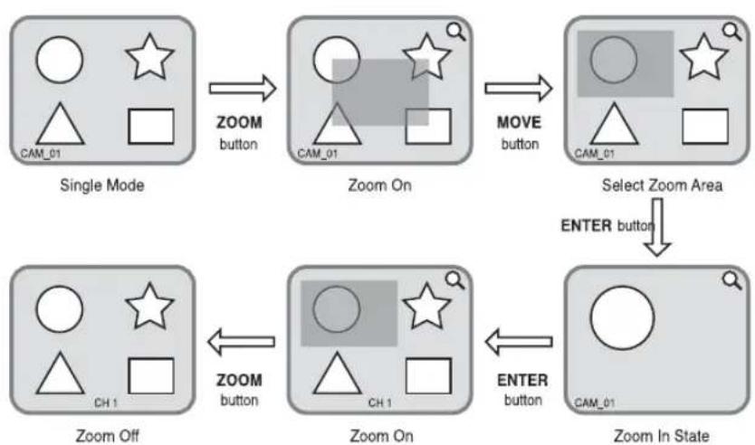
flowchart
graph TD
    A["Single Mode"] -->|ZOOM button| B["Zoom On"]
    B -->|MOVE button| C["Select Zoom Area"]
    C -->|ENTER button| D["Zoom In State"]
    D -->|ENTER button| E["Zoom On"]
    E -->|ZOOM button| F["Zoom Off"]
5
Event Monitoring
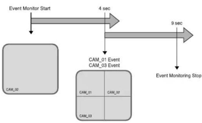
Event monitoring displays the channel synchronized with a event on the screen when a special event (Sensor/Motion/Video Loss) occurs. Event monitoring On/Off and event duration setup is available in [Menu] → [Monitoring] mode.
If you set the event monitoring interval to 5 seconds and an event occurs at CH2 in the beginning as following figure, the system will display CH2 in the full screen for 5 second.
If another event occurs within 5 seconds, it is displayed together with the existing event. As the following figure, both CH1 and CH3 events occur within 5 seconds (for example, after 4 seconds) after occurring CH2 event, these three events are split into 4 screens.
If the new event does not occurs during the event duration, the system will return to the previous Live mode. Pressing the [ALARM] button during the event duration makes the event monitoring stop. On occurring an event, [ALARM LED] is turned on. Press the [ALARM] button to turn [ALARM LED] off.
The alarm setup is initialized and the event icon disappears, and the event monitoring is off if it is on when pressing the [ALARM] button. After the alarm goes off, if the event recording, pre-event time, and post-event time have been set, then the event recording will go on for the duration of the setup time.
flowchart
graph TD
    A["Event Monitor Start"] --> B["CAM_02"]
    B --> C["4 sec"]
    C --> D["CAM_01 Event CAM_03 Event"]
    D --> E["Event Monitoring Stop"]
    E --> F["9 sec"]
Note
The Alarm LED does not turn off even though the event recording is finished. To turn the Alarm LED off, press the [ALARM] button.
Spot-out Monitoring
Spot-out Monitoring has nothing to do with Live Screen Output, it monitors the full screen of a certain channel. If you select the Monitoring in the MENU, the one channel among CH1 \~ CH4 is output with a Spot-out or channels are output one by one at an interval as Auto Sequence Mode in the Live Mode. Live screen icon does not appear in the spot-out monitoring.
The interval is as same as the Auto Sequence time in the Live Mode. If the Spot-out Event Monitoring is On, it is possible to see the event channel with Spot-out. In case of simultaneous event occurrence at more than one channel, the lowest numbered event channel has the first priority to be spotted out.
Caution
If the built-in HDD is not connected, or it operates with power applying in error,(☐) indicating "built-in HDD error" is displayed at the top of left.
At this time,
(1) Live screen mode
(2) Monitoring mode by Smart Viewer
operate only and the other functions including recording, search, playback, menu setup, and PTZ do not operate.
If the above problem is occurred, be sure to contact a service center to settle the problem.
Caution
If the fan in a set does not operate or has a problem, a fan error message pops up in the live screen as below picture. And the fan error icon 📋 appears at the top of left . If it is, check the fan in the set. The icon at the top of left disappears automatically if the fan recovers its operation.
| Fan Information |
| A error occurs in the fan. Refer to the manual. |
natural_image
Abstract digital illustration of circuit board patterns and server racks (no text or symbols)Chapter 5 Menu Setup
Before Use
- User validation for entering the MENU window
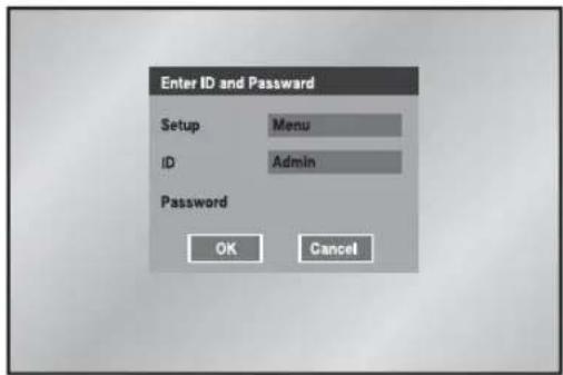
Press the "MENU" key to enter the Menu Setup window. Select Menu out of Menu, Backup, and Shutdown in the Setup field. (You can also perform the Backup and Shutdown functions after this user validation checkup.) The ID is fixed to Admin because only the user with Admin privilege can enter the Menu window. Input the Admin password you have defined and select OK.
text_image
Enter ID and Password Setup Menu ID Admin Password OK Cancel- Selection
The yellow cursor shows the current window. Use the ▲, ▼, ◀, ▶ key in the front to move the cursor on your desirous menu. If you press the "Enter" key with the cursor clicking on your desirable menu, the system will enter the new mode.
Press the "Enter" key to finish the selection. On seeing Drop Down Menu, use the ▲ or ▼ key to move the cursor on your desirable menu.
- "OK" or "Cancel" in Menu Setup Window
Once changed, the new menu setup procedure will be finalized by pressing "OK". Pressing "Cancel" will cancel the new setup and return to the upper menu.
● Front "MENU" and "SEARCH" Button
The MENU button or SEARCH button, if pressed first, acts as an entrance button. Once entering, it reverses the page to the previous one. When the MENU button is pressed in any of the Setup menus, it changes to the upper menu. If you press the MENU button in Live mode, the password window appears for user validation.
- The “>” or “V” mark beside the title copies the line in the arrow direction to the value of the first line.
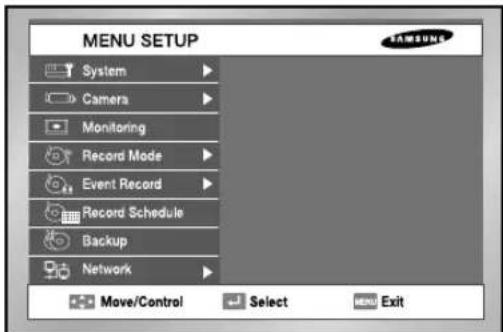
● The first page of the menu is structured as follows.
text_image
MENU SETUP System Camera Monitoring Record Mode Event Record Record Schedule Backup Network Move/Control Select MENU Exit1 System
● System Menu has the following items in detail.
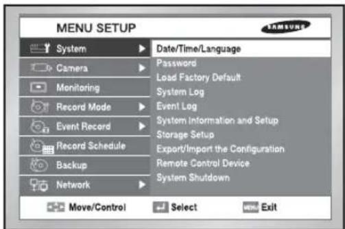
text_image
MENU SETUP System Camera Monitoring Record Mode Event Record Record Schedule Backup Network Date/Time/Language Password Load Factory Default System Log Event Log System Information and Setup Storage Setup Export/Import the Configuration Remote Control Device System Shutdown Move/Control Select ExitDate/Time/Language Setup
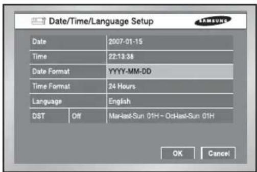
text_image
Date/Time/Language Setup Date 2007-01-15 Time 22:13:38 Date Format YYYY-MM-DD Time Format 24 Hours Language English DST Off MarLast-Sun 01H - OctLast-Sun 01H OK Cancel- Date
Press the "Enter" key and the ◀, ► key to move to Y/M/D.
Use the ▲, ▼ key to change the date.
Press the "Enter" key to come out of the mode.
• Time
Press the "Enter" key and the ◀, ► key to move to H/M/S.
Use the ▲, ▼key to change the time.
Press the "Enter" key to come out of the mode.
Once changed, the date and time will remain unchanged until you press "OK" or "Cancel".
Note
[Date/Time Change]
Pressing "OK" after you change date and time, you will be asked by a pop-up window if you really confirm the change. Here, press "Yes" to change the time. Since Date/Time does not change in backup process, be sure to stop the backup process before you change Date/Time. If the date or time is changed, the system reboots.
Caution
[Date/Time Change]
If the Date/Time changes to the original value, the data recorded before the change may be deleted. For example, if the time is changed from 8 am to 7 am, all the data recorded between 7 am and 8 am will be deleted.
- Date Format
The system supports 3 formats, YYYY-MM-DD / DD-MM-YYYY / MM-DD-YYYY.
- Time Format
The system supports 2 formats, 24 Hour / 12 Hour(AM/PM).
- Language
After selecting a language, OSD is expressed in the selected language. The available language is added in the list.
● DST (Daylight Saving Time)
DST sets the clock one hour ahead the local standard time. This setting enables the system to display the time adjusted for DST. If the DST is set to Off, it does not apply. To set the DST, enter the start time and end time on the right. It allows you to set month, week (e.g. 1st, 2nd, 3rd, 4th, last), day, and time.
Note
[On DST Setup]
Backup in progress will be cancelled. Recording in progress will be suspended for a moment until rebooting.
Caution
[Ending DST]
As the system goes one hour earlier, the data recorded since an hour ago will be deleted. As DST activates at the preset time, you are recommended to take the utmost care of preventing any trouble incurred by data deletion or rebooting.
Password
The factory default password for Admin and user privileges is "4321." In case of user privilege, you can select any of 5 users (User1 to User5) and assign user access rights for the selected user. If you press Setup in User Authority, all the access rights are selected.
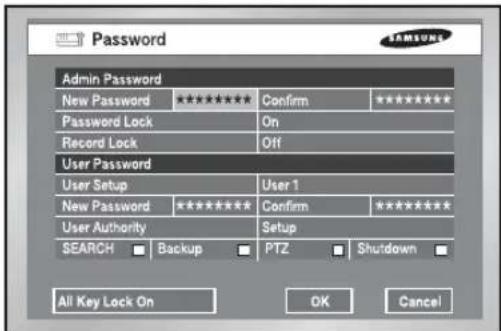
text_image
Password Admin Password New Password ***** Password Lock On Record Lock Off User Password User Setup User 1 New Password ***** Confirm ***** User Authority Setup SEARCH □ Backup □ PTZ □ Shutdown □ All Key Lock On OK Cancel● The Default Password is 4321.
- New Password
This is used to change the system password inside SHR-2160/2162/2080/2082. You are allowed to create a password up to 8 digits. Press the "Enter" key and a channel button from 1\~9,10(operates as 0) at the left. Press the "Enter" key after change to move to "New Password Confirm".
● New Password Confirm
This confirms a new password. You shall be obliged to input New Password in the above row first. Without New Password input, New Password Confirm input has no effect.
- Password Lock
If it is set to On, a pop-up window for user validation (You have to fill in the Setup, ID, and Password fields.) appears every time you select a menu. If it is set to Off, you can enter menus without entering the password.
- Record Lock
If the Record Lock is set to On, a pop-up window, asking for the password appears while disabling the recording.
- User Authority
You can select any of Search, Backup, PTZ, and Shutdown. As an example, if the user has no access right for Search, the user cannot enter the Search menu.
- All Key Lock On
If you select this, the system will enter the live mode immediately. If you press any button on the front panel or remote control, the password input window appears. If the correct password is input, the lock function is deactivated.
Note
[All Key Lock On]
If you select this, the system immediately switches to the live mode and all buttons are locked.
Load Factory Default

text_image
MENU SETUP System Camera Monitor Recover Event Recover Backup Network Date/Time/Language Password Load Factory Default Sure to default setting? OK Cancel Remote Control Device System Shutdown Move/Control Select MEN Exit- It used to initialize all the menu setup values. The recorded data will not be deleted. Press "OK" in the confirmation window to start initializing.
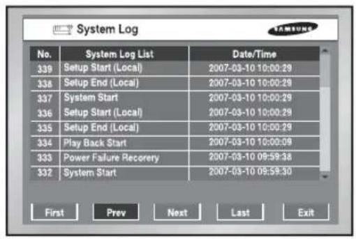
System Log
text_image
System Log No. System Log List Date/Time 339 Setup Start (Local) 2007-03-10 10:00:29 338 Setup End (Local) 2007-03-10 10:00:29 337 System Start 2007-03-10 10:00:29 336 Setup Start (Local) 2007-03-10 10:00:29 335 Setup End (Local) 2007-03-10 10:00:29 334 Play Back Start 2007-03-10 10:00:09 333 Power Failure Recovery 2007-03-10 09:59:38 332 System Start 2007-03-10 09:59:30 First Prev Next Last Exit● System Log is used to check the important record by an administrator.
- It displays such contents of a system related log and its execution date/time as System Start, System Termination, and Menu Setup Change.
- First : Moves to the first Log page.
● Prev : Moves to the previous Log page.
● Next : Moves to the next Log page.
● Last : Moves to the recent Log page.
Event Log
- It used to check the record regarding Event like Alarm / Motion / Video Loss.
- It displays the contents of a log regarding event and its execution date / time.
- First : Returns to the first Log page.
● Prev : Back to the previous Log page.
● Next : Forwards to the next Log page.
● Last : Moves to the recent Log.
- Event Log List
| Video Loss CH[N] Means the occurrence of Channel [N] Video Loss. | |
| Alarm Detection CH[N] Means the occurrence of Channel [N] alarm. | |
| Motion Detection CH[N] Means the occurrence of Channel [N] Motion. |
System Information and Setup

text_image
System Information and Setup System Information Software Version B3.03E.K1 30-V2_17-0702161543 Broadcast Format PAL Mac Address 00:16:BC:00:28:71 USB S/W Upgrade Version 83.07-K1 40-V2.17C_0703141732 OK CancelThis setup window provides the following setting items:
● Software Version: Displays the current software version. The value cannot be changed.
- Broadcast Format: Displays the current broadcast format (NTSC/PAL). The value cannot be changed.
● Mac Address: 6-Byte hardware address. The value cannot be changed.
- USB S/W Upgrade
You can update the software using an USB device. If there is no device, None is displayed. If the USB memory has an upgrade software, its version is displayed. To upgrade the software stored in the USB device, select the check box on the right and press OK.

Caution
[USB S/W Upgrade]
Download the software to upgrade at http://www.samsung.com, CCTV Part.
If the USB memory to upgrade has a format not being supported by DVR set, the upgrade is impossible.
In this case, use the "device erase" of menu 5-7 system information and setup.
Only one file to upgrade is allowed in the USB Memory.
Storage Setup
You can configure the storage device related settings.

text_image
Storage Setup Device Information Device No Used/Total Erase Usage ATA 1 295.00K/138.92G ■ Internal USB Memory 1 0.00/494.98M ■ Backup Disk End Mode OverWrite Disk End Beep Off SMART OK Cancel● Device Information
Displays the number, capacity, and usage of ATA and USB devices. The displayed values are not changed. You can remove the data in HDD or USB memory after checking in the Erase box.
- Disk End Mode
Stop: Stops recording when the disk is full while recording is still in progress.
Overwrite: Deletes the previously recorded data to store new data when the disk is full during recording.
- Disk End Beep
On: Beeps when the disk is full while recording.
Off: Although the disk is full while recording, it doesn't make beep sound.
Note 1
[Internal HDD]
This is a physical hard disk connected with the IDE cable inside the SHR-2160/2162/2080/2082 main body, and stores data.
[External HDD]
This is a physical hard disk connected with the port and terminal in the back of the SHR-2160/2162/2080/2082 main body, and stores data.
This can be used as Extended HDD or Backup HDD.
- Extended HDD : Supplements Internal HDD quantity. Connected, it takes the place of Internal HDD.
- Backup HDD : Backs up the data recorded in the set.
Note 2
[ATA]
Usage : Internal HDD
This is a physical hard disk connected with the IDE cable inside the SHR-2160/2162/2080/2082 main body.
[USB]
Usage : External HDD(Extended HDD or Backup HDD)
It is physical hardware that is connected to the front/back part of the SHR-2160/2162/2080/2082 with the USB port.

Caution
[Device Erase]
Data will not be deleted in the backup mode.
Please be sure to stop the backup before you delete a data. In the recording mode, suspend the recording and delete a data.

Caution
When the Disk end mode is set to Overwrite and the HDD overwrites the data that was previously backed up, the backup start time may be changed or the backup process may be cancelled.
[Disk Overwrite]
When Overwrite is selected, the previous event data is to be deleted and the mode is also changed.
Export/Import the Configuration
This menu is used to export or import the DVR-related settings to/from the USB memory.
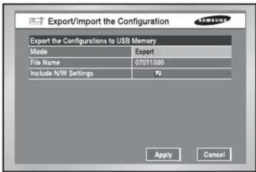
text_image
Export/Import the Configuration Export the Configurations to USB Memory Mode Export File Name 07011000 Include N/W Settings OK Apply CancelThe related settings are as the following:
● Mode: You can select any of Import and Export.
- File Name or File Open: The file naming is YYMMDD00 by default. "00" is the serial number so it increases by 1. If you want to change the file naming, press the ENTER button. The virtual keyboard appears for you to change the input value. In case of Import, the name of the import file that is included in the inserted USB appears. When the importing completes, your DVR automatically reboots.
- Include S/W Settings: In case of Export, it remains checked. But with Import, you can change the selection. Import/Export function does not affect for the Motion Detection Setup Area and Record Schedule.
Remote control Device
● MENU for the use of Samsung system keyboard
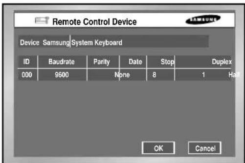
text_image
Remote Control Device Device: Samsung System Keyboard ID Baudrate Parity Date Stop Duplex 000 9600 None 8 1 Hall OK Cancel- Device
A Remote Control Device, being connected to the RS485 port.
• ID
This is a private ID of SHR-2040/2041/2042.
This private ID is essential for SSC-2000 because SSC-2000 can control many SHR-2040/2041/2042 DVRs.
- Baudrate
Baudrate to communicate with SSC-2000
It should be same to SSC-2000 Baudrate for communication.
- Parity
Sets up one of None / Even / Odd.
- Data
Sets up either 7 or 8.
- Stop
Sets up either 1 or 2.
- Duplex
Sets up either Half Duplex or Full Duplex.
Note
You cannot use the PTZ device device and remote control device at the same time, because of communication problems.
In PTZ control mode, DVR's PTZ mode is canceled when remote control mode is connected, and the remote control device is disconnected when the DVR changes to PTZ mode while controlling the DVR with a remote control device.
Refer to the remote control device manual on how to control the DVR's PTZ device in the remote control device.
System Shutdown

text_image
MENU SETUP System Camera Monil Reco Event Reco Backup Network Date/Time/Language Password Load Factory Default Sure to shutdown? OK Cancel Remote Control Device System Shutdown Move/Control Select MENU Exit- Terminates the work in action safely and turns the power off. Press "OK" in the confirmation window and plug out when you see "Safe to Power Off".

Caution
[System Shutdown]
Power-off without terminating the system in the System Shutdown menu may incur improper motion like data loss and disk failure. Power-off shall be done in the System Shutdown menu.
2 Camera
● The detailed Camera Menu items are as follows.

text_image
MENU SETUP System Camera Monitoring Record Mode Event Record Record Schedule Backup Network Camera Configuration PTZ Device Screen Setup Move/Control Select MENU ExitCamera Config.

text_image
Camera Config Cam Video/Audio ✓ Title Auto Seq 1 On Off CAM_01 5sec 2 On Off CAM_02 5sec 3 On Off CAM_03 5sec 4 On Off CAM_04 5sec CancelOK- Video
On : Camera images from a selected channel appear.
Off: Camera images from a selected channel disappear.
Covert1 : Displays the information except for the Video information of selected channel.
Covert2 : Does not display the any information.
Audio/Cam name/Auto sequence setup are impossible in the Off channel.
● Audio
On : Makes the sound of selected channel on.
Off: Makes the sound of selected channel off.
• Title
You can name the camera of selected channel.
If you press the [Enter] key, the Virtual keyboard will come out.
▶ Virtual Keyboard
If you move the cursor, you can type text by text.
Up to 15 texts can be typed.
Keyboard cannot be composed of all spaces.
Pressing Caps Lock changes the keyboard that can be selected. (2 Modes)

text_image
CAM_01 A B C D E F G H I J K L M N O P Q R S T U V W X Y Z 1 2 3 4 5 6 7 8 9 0 - = ( ) ! - - < > ? CapsLock Delete << Back Space OK Cancel● Auto Sequence
You are allowed to set the duration of each channel at the Auto Sequence channel in the Live Mode.
A channel, set to Off, does not operate in the Auto Sequence Mode.
PTZ Device
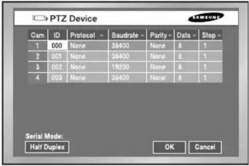
text_image
PTZ Device Cam ID Protocol -Baudrate Parity Data Stop 1 000 None 38400 None 8 1 2 001 None 38400 None 8 1 3 002 None 19200 None 8 1 4 003 None 38400 None 8 1 Serial Mode: Half Duplex OK Cancel• ID
It is an ID for PTZ Camera and available to set from 0 to 255.
- Protocol
It is supported by the PTZ device.
The following protocols are now being supported.
Samsung / Vic. / Pan. / AD / Phi. / Ern. / Pel-D / Pel-P / Vcl. / Dia. / Kal. / Tech.
• Baurate
Baurate is supported by the PTZ device. 600 / 1200 / 2400 / 4800 / 9600 / 19200 / 38400
- Parity
It is set to the one of None, Even, and Odd.
- Data
It is set to either 7 or 8.
- Stop
It is set to either 1 or 2.
- Duplex
It is set to either Half Duplex or Full Duplex.

Caution
The above items shall be same to the PTZ device setup.
For the details, please refer to User Manual of the PTZ device manufacturer.
Screen Setup
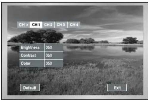
text_image
CH > CH1 CH2 CH3 CH4 Brightness 050 Contrast 050 Color 050 Default Exit- It is a window to set Brightness/Contrast/Color for the camera image of each channel. Put the cursor on the channel that you want to adjust and set Brightness/Contrast/Color. Once selected, the channel appears in the right PIP area. Use the ▲ or ▼ button to adjust the value from 0 to 100.
- If you select CH >, all the channels will have the same values as the selected channel.
- "Default value" resets the current channel to the basic value of 50.
3 Monitoring
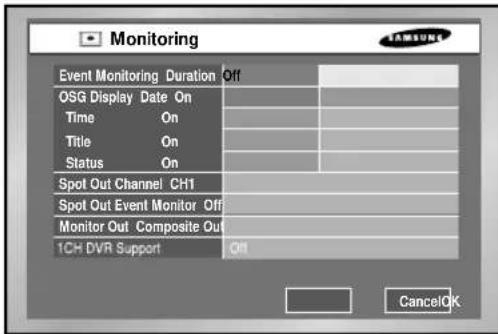
text_image
Monitoring Event Monitoring Duration Off OSG Display Date On Time On Title On Status On Spot Out Channel CH1 Spot Out Event Monitor Off Monitor Out Composite Out 1CH DVR Support Off Cancel OK- Event Monitoring
It is possible to set to Off / 3sec / 5sec / 10sec / 20sec / 30sec / Continuous.
① Off : Event Monitoring does not operate to turn to the screen where an event occurs.
② 3sec / 5sec / 10sec / 20sec / 30sec : Sets the duration time of screen in the Auto Sequence mode.
③ Continuous : The Event Monitoring screen remains alive until you press the "Alarm" button in the front to cancel the screen manually.
- OSG Display
① Date : The date is displayed on the screen when it is On, and not displayed when it is Off.
② Time : The time is displayed on the screen when it is On, and not displayed when it is Off.
③ Cam name : The Cam name is displayed on the screen when it is on, and not displayed when it is off.
④ Status : Audio/Ptz is displayed on the screen when it is on, and not displayed when it is off.
- Spot Out Channel
Spot Out channel is used to let one of two monitors monitor a channel, focusing on it. Spot Out channel supplies two functions, continuous monitoring of only one channel and Auto Sequence to display all the channels one by one.
① Auto Sequence setup ranges from Ch1 to Ch 4.
② In the Auto Sequence mode, Spot Out channels are displayed in turn.
③ Duration time for Auto Sequence is as same as set for Camera setup.
- Spot Out Event Monitor
Sets if event monitoring will be executed for Spot Out channels.
① Off : The event monitoring dose not operate in the Spot Out channel.
② 3sec / 5sec / 10sec / 20sec / 30sec : Sets the duration time of screen in the Auto Sequence mode.
③ Continuous : Once scrolled down, the screen remains displayed until you delete "Alarm" LED in the front manually.
- Monitor
You are not allowed to connect VGA OUT and Composite / S-Video OUT simultaneously. Consequently, the user is obliged to choose either Composite Output or S-Video Output.
① Composite : Makes the output come out through the "Composite / S-Video OUT" port.
② VGA : Makes the output come out through the "VGA Out" port.
When changing the output from Composite to VGA or from VGA to Composite, the system reboots automatically.
- Multi-channel change
You can set changes for a split screen.
You can set it to 3, 5, 10, 20, or 30 seconds.
● 1 CH Support
1 CH DVR is supported. If 1 CH Support is On, 1 CH is supported.
If 1 CH Support is Off, 4 CH is supported.
If 1 CH Support is On, a set reboots and support 1 CH.

Caution
[Video Out]
When setting the Composite Output, VGA output does not come out.
When setting the VGA Output, Composite Output does not come out.
If you press the No. 1 button for 5 seconds in the Live Mode with keeping the MODE button pressed, the system will change from VGA to COMPOSITE or from COMPOSITE to VGA and reboot.
[1 CH support]
In the case of 1 CH support, the event monitoring, Spot out channel, Spot out event monitoring cannot be set.
Full D1/Half D1/CIF is supported for the video size in the 1 CH.
If the Full D1 is set and 1 CH support Off is selected, the video size in the 4 CH set to CIF. In the 1 CH setup, the system value is initialized.
[Video Output]
VGA output : 640 X 480 (60Hz)
4
Recording Mode
Record Mode
● Details for Record Mode Menu are as follows.
NTSC

text_image
Record Mode Cam Mode Quality Rate 1 On Very High 15.00 ips 2 On High 15.00 ips 3 On High 15.00 ips 4 Off Low 15.00 ips Video Size : Half D1 OK CancelPAL

text_image
Record Mode Cam Mode Quality Rate 1 On Very High 8.33 ips 2 On High 8.33 ips 3 On High 8.33 ips 4 Off Low 8.33 ips Video Size : Half D1 OK CancelIf you press the front "REC" button, the mode value to be recorded will be set.
For the setup of Event Recording Mode value, refer to 5-20. Event Recording Mode Setup Menu.
- Mode
On : The current channel is recorded if the REC button is pressed.
Off : The current channel is not recorded even thought the REC button is pressed. The default value is set to "On".
• Quality
It sets the Quality.
Set to the one among Very High / High / Standard / Low
- Rate
It sets the Rate means the number of screen recorded every second.
If it is set to 15.00 ips(NTSC) / 12.50 ips(PAL), the system records too many screens per second and the playback continues intermittently since recording is more detailed.
This is appropriate for concentrated monitoring zone setup.
In case of NTSC, select one out of 30.00 ips / 15.00 ips / 10.00 ips / 7.50 ips / 5.00 ips /
3.00 ips / 1.00 ips. In case of PAL, select one out of 25.00 ips / 12.50 ips / 8.33 ips /
6.25 ips / 5.00 ips / 2.50 ips / 1.00 ips. The Recording Menu will be activated depending on Video On/Off in the Camera Setup (Menu5-12). When less than 2 cameras are activated at HALF D1, the frame rate of recording may start from 30.00 IPS and when more than
3.00 cameras are activated at Half D1, the frame rate of recording may start from
15.00 ips(NTSC) / 12.50 ips(PAL). CIF supports from 30.00 ips(NTSC) / 25.00 ips(PAL) regardless of the number of activated camera.
- Video size
The Video size is displayed at the bottom of left.
- When changing to a 1-channel DVR, it only supports 30.00 ips in the Full D1 resolution.
Record Video size Mode

text_image
Record Video Size Mode Video Size Half D1 (N) Auto Deletion Off 01 Day OK Cancel- Video size
It sets the video to be recorded.
Half D1 : (NTSC) 720x240(N) → Normal
(PAL) 720x288(N) → Normal
CIF : (NTSC) 352x240(C) → CIF
(PAL) 352×288(C) → CIF
● Auto Deletion
If you click the [off] button, you can select from on/off.
Select "On" to move to the Date selection button and to limit the search date.
If you select "Off", you cannot move to the Date selection button and to limit the search date.
The date is limited from 1 to 99 days.
Note
To select Full D1, set 1 CH Support to On in the monitoring mode.
5
Event Record Mode
● The detailed items of Event Record Menu are as follows.

text_image
SHR-4160 MENU System Camera Monitoring Record Mode Event Record Record Schedule Backup Network Event Record Mode Setup Alarm Detection Setup Motion Detection Setup Video Loss Detection Setup Move/Control Select MOV ExitEvent Record Mode setup
NTSC
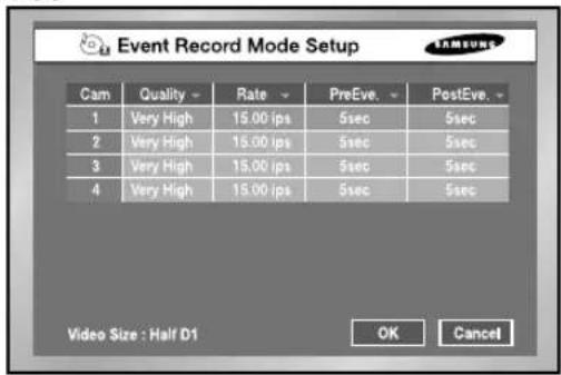
text_image
Event Record Mode Setup Cam Quality Rate PreEve. PostEve. 1 Very High 15.00 ips 5sec 5sec 2 Very High 15.00 ips 5sec 5sec 3 Very High 15.00 ips 5sec 5sec 4 Very High 15.00 ips 5sec 5sec Video Size : Half D1 OK CancelPAL

text_image
Event Record Mode Setup Cam Quality Rate PreEve, PostEve, 1 Very High 8.33 ips 5sec 5sec 2 Very High 8.33 ips 5sec 5sec 3 Very High 8.33 ips 5sec 5sec 4 Very High 8.33 ips 5sec 5sec Video Size : Half D1 OK Cancel● Event Record Mode setup
Sets a mode to be recorded when an event occurs.
● V. Size (Video Size)
Sets the size of a screen to be recorded.
Half D1 : (NTSC) 720x240(N) → Normal
(PAL) 720x288(N) → Normal
CIF : (NTSC) 352x240(C) → CIF
(PAL) 352×288(C) → CIF
● Quality
Quality will be determined.
Select the one among Very High / High / Standard / Low
- Rate
Sets the Rate the number of screen recorded every second.
It you set to 15.00 ips, the system records too many screens per second and play continues intermittently since recording is more detailed. This is appropriate for concentrated monitoring zone setup.
In case of NTSC, select the one of 30.00 ips / 15.00 ips / 10.00 ips / 7.50 ips / 5.00 ips / 3.00 ips / 1.00 ips.
In case of PAL, select the one of 25.00 ips / 12.50 ips / 8.33 ips / 6.25 ips / 5.00 ips / 2.50 ips / 1.00 ips.
- The Event Recording setup menu will be activated depending on Video On / Off in Camera Setup (Menu5-12).
- When the video size in the Camera Setup Menu is set to Half D1 and less than 2 cameras are activated, the frame rate of recording may start from 30.00 ips(NTSC) / 25.00 ips(PAL) and when the video size in the recording mode is set to Half D1 and more than 3 cameras are activated, the frame rate of recording may start from 15.00 ips(NTSC) / 12.50 ips(PAL). CIF supports from 30.00 ips(NTSC) / 25.00 ips(PAL) regardless of the number of activated camera.
- Pre-Event(PreEve)

text_image
Pre-Event Section Event timeRecords the situation until Alarm is issued.
Off : No recording
5sec / 10sec / 20sec / 30sec : The recording time options before Alarm issue
● Post-Event(PostEve)
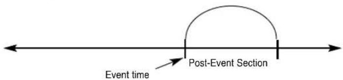
text_image
Event time Post-Event SectionRecords the situation since Alarm is issued.
Off : No recording
5sec / 10sec / 20sec / 30sec / 1min / 3min / 5min / 10min / 20min : Sets the recording time after an event occurs.
- Video size
The Video size is displayed at the bottom of left 5-19.
- When changing to a 1-channel DVR, it only supports 30 ips in the Full D1 resolution.
Alarm Detection Setup
- Off : Sensor does not operate.
① N.O(Normal Open) Sensor : Sensor remains open all the time and if closed, an alarm will be issued. (A Contact)
② N.C(Normal Close) Sensor : Sensor remains closed all the time and if open, an alarm will be issued. (B Contact)
- Cam
Sets a camera that will synchronize with the current sensor. The default value is currently set to the sensor number. A sensor shall be synchronized with at least a camera. Multi-selection is possible.
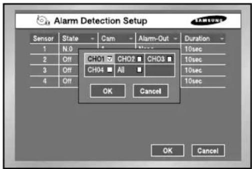
text_image
Alarm Detection Setup Sensor State Cam Alarm-Out Duration 1 N.0 2 Off CHO1 CH02 CH03 3 Off CH04 All 4 Off OK Cancel OK Cancel- Alarm-out
Sets the Alarm-Out when Alarm Sensor sounds.
5 Alarm Outs are supported un the present.
Choose an alarm-out that you want to synchronize with the current sensor.
Multi-selection is possible.
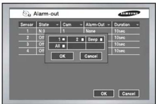
text_image
Alarm-out Sensor State Cam Alarm-Out Duration 1 N.0 1 None 10sec 2 Off 1 ■ 2 ■ Beep ■ 10sec 3 Off All ■ 10sec 4 Off 10sec OK Cancel OK Cancel- Duration
Sets the Alarm-Out Duration. Alarm-Out continues for the set value.
Off / 3sec / 5sec / 10sec / 20sec / 30sec / Continuous
Motion Detection Setup
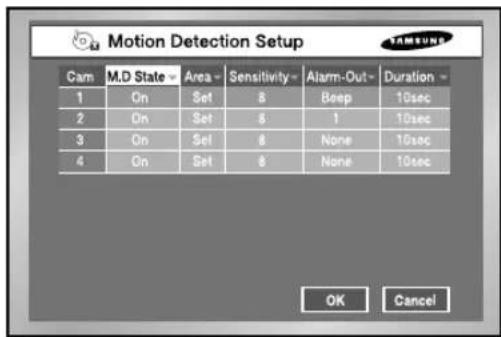
text_image
Motion Detection Setup Cam M.D State Area Sensitivity Alarm-Out Duration 1 On Set 8 Beep 10sec 2 On Set 8 1 10sec 3 On Set 8 None 10sec 4 On Set 8 None 10sec OK Cancel● Motion Detection Mode
Off : Motion Detection does not operate
On : Motion Detection operates.
- Area
Selects the Motion Detection area. It is composed of 45x40(NTSC)/45x48(PAL) sized Block. It is impossible to set 4 block rows(Up/Down/Left/Right) to allow them to be displayed in all monitors.
▶Select All : Selects the whole area.
▶Select Block : Selects a block every time. Selection is done by a toggle system.
▶ Select Quarter : Splits the whole area into 4 pieces, which enables selecting a fourth of the whole area.
▶ Clear All : Cancels the whole area.
▶ Save & Exit : Saves and exits.
▶Exit : Exits without saving.
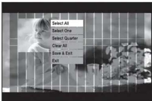
text_image
Select All Select One Select Quarter Clear All Save & Exit Exit- Sensitivity
Sets the sensitivity of motion detection. Sensitivity: 1(L), 2, 3, 4, 5, 6, 7, 8, 9, 10(H).
- Alarm-Out
Sets the Alarm-Out when Motion occurs.
5 Alarm Outs are supported.
Select an alarm-out that you want to synchronize with the current motion channel. Multi-selection is possible.
- Duration
Sets the Alarm-Out Duration. Alarm-Out continues for the determined duration. Off / 3sec / 5sec / 10sec / 20sec / 30sec / Continuous
Video Loss Detection Setup
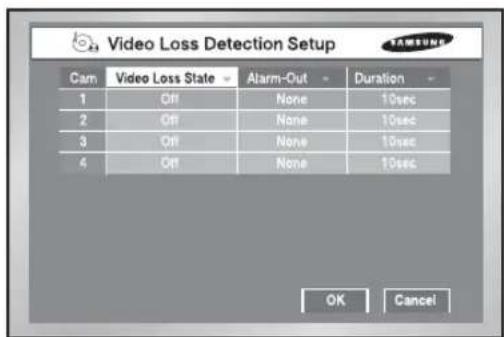
text_image
Video Loss Detection Setup Cam Video Loss State Alarm-Out Duration 1 Off None 10sec 2 Off None 10sec 3 Off None 10sec 4 Off None 10sec OK Cancel- Video Loss State
Off : Video Loss does not operate. On : Video Loss operates.
- Alarm-Out
Selects the Alarm-Out when the current Video Loss occurs.
3 Alarm Outs are supported in the present. Select an alarm-out that you want to synchronize with the current motion channel. Multi-selection is possible.
• Duration
Sets Alarm-Out Duration. Alarm-Out continues for the determined duration. Off / 3sec / 5sec / 10sec / 20sec / 30sec / Continuous
Record Schedule
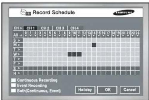
text_image
Record Schedule CH > CH 1 CH 2 CH 3 CH 4 All 0 1 2 3 4 5 6 7 8 9 10 11 12 13 14 15 16 17 18 19 20 21 22 23 S > M > T > W > T > F > S > H > Continuous Recording Event Recording Both(Continuous, Event) Holiday OK CancelThis setup selects a time to record automatically.
Selection by the day or by the time is available.
The default value is set to "Event Record".
- Press "CH >" copies the value of Channel 1 to all the channels.
● The horizontal axis numbered from 0 to 23 represents the time value.
The vertical axis numbered from S to H represents the day value. (H : Holiday) Selection by the day or by the time is available. - Pressing "ALL" converts the overall setting of the selection window into Continuous → Event Record → Schedule/Event Record.
- Record Schedule
Recording starts automatically on the preset time.
Recording follows the condition that set in 5-18. Record Mode.
Refer to 7-2 Record Schedule.
- Event Recording
Recording starts automatically when an event (Alarm/Motion Detection/Video Loss) occurs within a setup time.
Recording follows the condition that set in 5-20. Event Record Mode setup.
Refer to 7-3 Event Recording.
- Schedule Record is yellow, Event Record is Blue, and Schedule/Event Record is red.
- Schedule / Event Record
On occurrence of Event, Continuous Recording is replaced with Event Recording Mode.
- Holiday
If you press "Holiday", a calendar pops up and you are able to designate holidays.
Move to a date and press "Enter" to complete designation.
Press "Enter" once more to cancel designation.
"H" at the bottom of the table means a holiday.

text_image
Holiday setup Jan Sun Mon Tue Wed Thu Fri Sat 1 2 3 4 5 6 7 8 9 10 11 12 13 14 15 16 17 18 19 20 21 22 23 24 25 26 27 28 29 30 31 OK Cancel7 Backup

text_image
Backup Start Date/Time End Date/Time 2007-03-22 01:20:00 2007-03-23 10:00:00 CH1 CH2 CH3 CH4 Folder/Filename 20070322 / 0120 Select/Free : 9.60G / 72.72G Backup Dev : USB Memory ✓ AVI USB Memory Start Cancel- If there is a device, the free space and the backup device is displayed.
- Select a date, time, and camera No. to backup, and press "Start".
- When you change Start Date/Time or End Date/Time, free space keeps updated in the Free Space zone. But the Select/Free values are displayed when you have marked the Check box.
- A file name is composed of Folder/File Name. A folder is composed of the backup date(YYYYMMDD) while a file name is composed of the time(HHMM). A file may be renamed by the virtual keyboard. It can display up to 4 letters for a file name.
- When there is no file name, the default name is hhmm.
The backup menu's virtual keyboard does not support special keys or the space bar.
- If there is no backup device, Warning sign pops up. Select and connect Backup Device in 5-8.HDD Setup and proceed the backup.
- Press the "Stop" to stop the backup.
- Pressing Cancel during the Backup returns to the upper menu but this does not affect the backup process.
- A USB CD/DVD and built-in CD can only set up AVI. You can play back an AVI backup in a PC. The USB memory can be set up for AVI check.

Caution
[In Backup Process]
If you press Exit while the backup is in progress, the screen goes to the upper menu but it does not affect the backup process. Press "Stop" to stop the backup. The speed of the set may down during the backup.
- When backing up to USB CD/DVD or memory, you must use a smaller capacity than the device's true capacity. (Part of the capacity is used for the system)
- It doesn't support backing up with memory cards, flash cards, and memory sticks such as SD, CF, MMC, etc. Also, it doesn't support USB backup with the adapters of the devices listed above.
- A USB CD/DVD and built-in CD can only set up AVI. You can play back an AVI backup in a PC.
- The USB memory can be set up for AVI check.
When there is no file name, the default name is hhmm.
The back up menu's virtual keyboard does not support special keys or the space bar.
- The file name is created with the start time of backup data. (YYYYMMDD)/(HHMM+ four digits of the serial number) The backup file can be separated in the following conditions:
- Different units in file size (1GB for DVD, 2GB for others)
- Change in recording conditions
- Discontinuous recording data
- When the CD or DVD is malfunctioning, the USB CD/DVD or built-in CD tray opens and closes, the backup will fail. In this case when the backup fails due to media malfunction, try to backup again after changing to a new media.
Warning
The backup data could be damaged by the state of writing surface of disk in the case of CD/DVD backup.
Note
- SHR-2042 supports the internal CD-R/W.
- In case of AVI backup, the backup playback is available in the PC, but it is not available in the DVR.
Codec is required to play an AVI backup file, which is also copied along with the installation file in the AVI backup process. Run a codec setup file, "MP4Codec.exe", to install the codec on the PC.
"INDEX.xml" is included in the AVI backup file, which enables you to check and enjoy a desired file at your convenient time.
- In case of USB external HDD and USB Flash Memory, the backup is available only with formatting FAT32 partition.
To format FAT32, Format the device as FAT32 in the PC or erase the device in the Storage Setup menu, which enable to backup files.
- In case of back-up devices, please check the compatibility list of the storage devices. The list of the compatible devices with Samsung DVR can be obtained from your vendor.
- The backup of the AVI format may take longer depend on a number of the channel and the DVR operation environment (e.g. recording, network)
8 Network
IP Setup

text_image
95 IP Settings Connection Mode Static IP Bandwidth 2 Mbps Admin Password ***** User Password ***** IP 192.168.001.201 Gateway 192.168.001.001 Subnet Mask 255.255.255.000 DNS 168.126.036.001 ADSL User ID ID Password ***** OK Cancel- Connection Mode
Designates the kind of the network connected to the main body of SHR-2040/2041/2042.
Static IP : When the main body is connected to the network with Static IP.
Dynamic IP : When the main body is connected to the network with Dynamic IP supplied by DHCP.
ADSL(PPPoE) : When the main body is connected to the ADSL network with PPPoE.
- Bandwidth
Designates the network speed to which the main body of SHR-2040/2041/2042 is connected.
Unlimited / 2 Mbps / 1.5 Mbps / 1 Mbps / 800 Kbps / 600 Kbps / 500 Kbps / 400 Kbps / 300 Kbps / 128 Kbps
If the connection is made via ADSL, you can only select a bandwidth of 600 kbps or less.
Caution
- If the main body of SHR-2040/2041/2042 is connected to a high-speed network like LAN, you are recommended to set the bandwidth to higher than 1 Mbps.
- If the device is connected to a network with ADSL or low bandwidth, set the bandwidth not to exceed 600kbps, and set the recording mode not to exceed CIF (standard).
Setting up to a high bandwidth or recording mode on a network environment supporting low bandwidth may cause a network overload, therefore connection with the smart viewer or image monitoring may not operate properly. - When connection mode is set to ADSL, the IP settings page's bandwidth is set at 300kbps and the protocol setting page's protocol adapter is set to TCP.
Note
In case of ADSL, the Protocol type is fixed to TCP.
- Admin Password
Used for the connection between Smart Viewer and the set with the authority of Admin.
The password can be input 8 digits in maximum.
Press "Enter" and the left numeric keys from 1 to 4 for setup.
The default password for ADMIN is 4321.
- User Password
Used for the connection between Smart Viewer and the set with the authority of user.
The password can be input 8 digits in maximum.
Press "Enter" and the left numeric keys from 1 to 4 for setup.
The default password for USER is 4321.
• IP
Sets the IP address for the main body of SHR-2040/2041/2042 to connect with the network. If the Connection Mode is set to Static IP, you shall type in IP yourself. If the connection mode is Dynamic IP or ADSL(PPPoE), the IP allocated by the DHCP server or ADSL company will be automatically displayed. In case of failure of DHCP or ADSL connection, 000.000.000.000 will be displayed. Then, press OK to retry connection to get IP. If you continue to fail in DHCP or ADSL connection, keep the main body of SHR-2040/2041/2042 off for a while and turn it on for retry.
- Gateway
Sets the Gateway Address in the SHR-2040/2041/2042 main body.
- Subnet Mask
Sets the Subnet Mask Address in the SHR-2040/2041/2042 main body.
• DNS
Sets the DNS Address in the main body of SHR-2040/2041/2042. The default value of DNS is 168.126.63.1. Generally, you don't have to alter the DNS default but you may be hard to connect to the network sometimes if you use DHCP or ADSL. In this case, call the network manager or ADSL company to set up a new DNS address.
- ADSL User ID
If the main body of SHR-2040/2041/2042 is connected with the ADSL(PPPoE) network, input User ID subscribed to the ADSL company. You may input User ID with a Virtual keyboard as long as 40 digits irrespective of alphabets, numbers, or symbols.
- Password
If the main body of SHR-2040/2041/2042 is connected to the ADSL(PPPoE) network, input the user password subscribed to the ADSL company. You may input the password with a Virtual keyboard as long as 40 digits irrespective of alphabets, numbers, or symbols.
Caution
Be sure to set IP/Port/SubnetMask/Gateway/DNS to let Smart Viewer connect with the main body of SHR-2040/2041/2042.
Wrong IP/Port/Gateway/SubnetMask/DNS may prevent Smart Viewer from being connected to the main body of SHR-2040/2041/2042.
Please call the network manager or ADSL company to get each setting value.
Caution
In case of ADSL, the audio is not played in the SmartViewer.
Transfer Protocol Settings
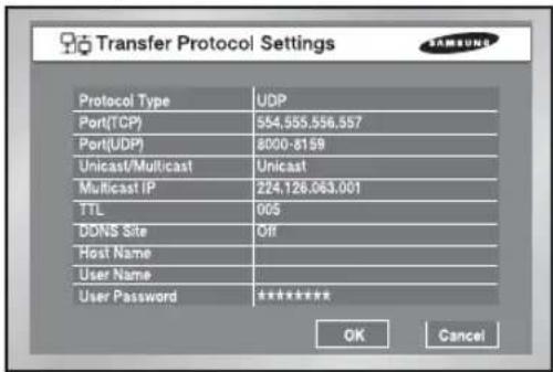
text_image
Transfer Protocol Settings Protocol Type UDP Port(TCP) 554,555,556,557 Port(UDP) 8000-8159 Unicast/Multicast Unicast Multicast IP 224,126,063.001 TTL 005 DDNS Site Off Host Name User Name User Password ***** OK Cancel- You may select either TCP or UDP for the protocol type. If you select ADSL from the IP setup page, only TCP is available. While TCP is selected, Audio transmission is not available.
- The available Port(TCP) ranges from 554 to 998 and the port number will be changed by 4. Once the first digit is determined, the following 3 digits will change accordingly.
● The available Port(UDP) ranges from 8000 to 9760 and the port number will be changed by 160. Once the first digit is determined, the remaining digits will change accordingly.
- Unicast is set to the default value and Multicast can be selected in Unicast / Multicast.
- Multicast IP will be activated and its setup is available only when Multicast is selected from Multicast/Unicast.. Select a number from 224.0.0.0 to 239.255.255.255 for the D-Class IP address.
- TTL will be also activated and the value from 1 to 255 can be set only when Multicast is selected from Multicast / Unicast. The default value is 5.
- DDNS Setup
- You may select the DDNS Site as Off, Samsung DDNS, dyndns.com, no-ip.com, or changeip.com.
- If you select Off, the IP will not be registered in DDNS.
- If you select Samsung DDNS, the IP will be registered in the DDNS operated by Samsung. Select MAC Address as the Address Type in the Setup → Site Setup → DVR registration window of the SmartViewer, and enter the MAC Address of, then you can connect remotely using the Samsung DDNS.
- dyndns.com, no-ip.com, and changeip.com are free Public DDNS websites that a URL can be allocated by registering a Dynamic IP.
Become a member of the desired website, register the URL, and then set up your Host Name, User Name, and User Password.
Select URL as the Address Type in the Setup → Site Setup → DVR registration window of SmartViewer, and enter the Host Name (URL) that is allocated by the Public DDNS website, then you can connect remotely using the URL.
Note
If you set up the Public DDNS (dyndns.com, no-ip.com, or changeip.com), it will take approximately 30-60 seconds for the IP address of the Host Name (URL) to be updated in the DNS.
Note
If you want to connect IP Router with the main body of SHR-2040/2041/2042, you shall designate a port for SHR-2040/2041/2042 in the IP Router setup menu.
The main body of SHR-2040/2041/2042 uses 4 ports for TCP communication.
In addition, if you want to use the DHCP function backed by IP Router to allocate Dynamic IP to the main body of SHR-2040/2041/2042, you shall designate a port for the IP which SHR-2040/2041/2042 has been allocated by the IP Router setup menu.
If you use IP Router, you are recommended to rather determine IP and Port numbers to be allocated to the main body of SHR-2040/2041/2042 from the IP Router setup menu, set the connection mode to Static IP for the main body of SHR-2040/2041/2042, and input the determined IP and Port number in IP Router than use the DHCP function.
Please refer to the IP Router User's Manual or call the manufacturer to set up IP Router.
Callback Settings
- The Callback function is used to forward a callback message to the IP where SmartViewer is in action in case Alarm, Motion Detection, or Video Loss event occurs.
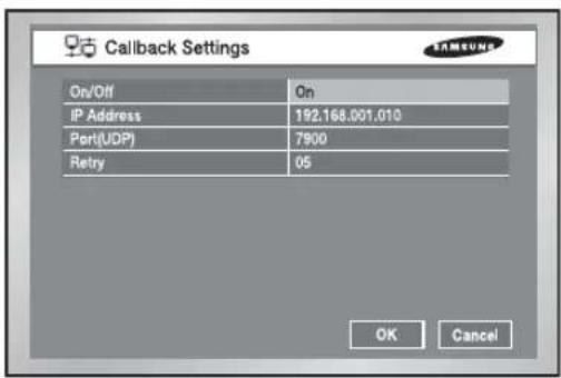
text_image
Callback Settings On/Off IP Address Port(UDP) Retry On 192.168.001.010 7900 05 OK Cancel● On/Off : Off is default but you may choose On.
- IP Address : IP setting is available only when On is selected from On/off Setting. Select the IP address of PC where SmartViewer is in action.
- Port(UDP) : You may choose one from 7900 to 7999 and the number changes by 1. Selects the Port value for the Callback Connection menu from SmartViewer Setup.
● Retrial : You may choose one from 1 to 20 and the number changes by 1.
Caution
- Though Callback is set to ON, any Callback message will be created unless Alarm, Motion Detection, and Video Loss are set by EventRecord.
- Unless the Callback button is clicked, SmartViewer does not receive any Callback message.
Port Setup for SmartViewer Connection
- The Port value for DVR registration of SmartViewer (Setup → Site Setup) shall be as same as that of the set (TCP).
- If you want to use the IP Router, you shall forward the activated Port depending on the current setting value.
- If set to TCP, allocate 4 ports to the IP Router whose Port(TCP) was set.
- If set to UDP, allocate 4 ports whose Port(TCP) was set and 160 ports whose Port(UDP) was set to the IP Router.
In the event of TCP Setup from Transfer Protocol Setup Page
- The ports allocated to Port(TCP) will be used for SmartViewer connection control and stream forwarding.
In the event of UDP Setup from Transfer Protocol Setup Page
- The ports allocated to Port(TCP) will be used for SmartViewer connection control and the ports allocated to Port(UDP) will be used for stream transfer.
- If you set to Multicast
- Both MultiCast IP and TTL Setup will be activated.
- MultiCast IP means the group address(D-Class IP Address : 224.0.0.0 \~ 239.255.255.255) for MultiCast Forwarding.
- TTL(Time To Live) indicates how many Routers will be passed for MultiCast Forwarding.
- When you are unable to use Multicast by the Network(LAN or ADSL) characteristic as both Set and SmartViewer are installed, the message, "Not Connected" will be displayed in the SmartViewer screen. Please alter the TCP or UDP(Unicast) setting value.
● In the event of poor image from SmartViewer
- When the bandwidth of the network where Set is installed is smaller than the quantity of transfer stream packet, the image is sometimes poor. Set the IP setup bandwidth lower than the current setting value. (In case of ADSL, it is recommended 300Kbps or 600Kbps for the bandwidth.)
- If this effort is no use, alter the protocol type to TCP.
natural_image
Abstract digital illustration of circuit board patterns and server racks (no text or symbols)Chapter 6 PTZ Camera Control
1
PTZ Camera Control Mode
- Select a proper PTZ camera Configuration value in MENU to enter PTZ Control Mode.
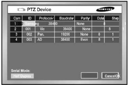
text_image
PTZ Device Cam ID Protocol/ Baudrate Parity Data Stop 1 002 Samsung 38400 None 6 2 001 Vic 38400 None 8 3 002 Pan. 19200 None 8 1 4 003 AD 38400 Even 8 1 Serial Mode: Half Duplex CancelOK- Selected in MENU, the PTZ symbol(PTZ) is displayed on the channel in the screen.
- If you press the Enter(←J) button among direction keys in front of Split Screen, a blue bar will appear in the monitor screen. Use direction keys to move this bar until you reach the channel with the PTZ symbol and press the PTZ button in front of SHR-2040/2041/2042 to enter PTZ Camera Control Mode.
If you succeed in entering PTZ Camera Control Mode, the PTZ symbol on the monitor screen will turn yellow from white while the PTZ button in front of SHR-2040/2041/2042 will turn blue. PTZ Camera Control Mode supports Pan, Tilt, and Zoom operation.
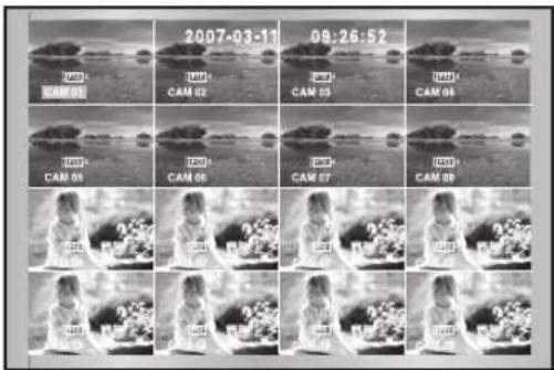
text_image
2007-03-11 09:26:52 CAM 01 CAM 02 CAM 03 CAM 04 CAM 05 CAM 06 CAM 07 CAM 08 CAM 09 CAM 10 CAM 11 CAM 12 CAM 13 CAM 14 CAM 15 CAM 16 CAM 17 CAM 18 CAM 19 CAM 20 CAM 21 CAM 22 CAM 23 CAM 24 CAM 25 CAM 26 CAM 27 CAM 28 CAM 29 CAM 30

- Other PTZ Camera Control Modes perform its control in a single screen. Press the channel selection button in the left front to select the PTZ setting channel and press the PTZ button. If you succeed in entering Single Screen PTZ Camera Control Mode, the PTZ symbol on the screen will turn yellow from white while the PTZ button will turn blue. Single Screen PTZ Camera Control Mode supports Pan, Tilt, and Zoom operation basically and Preset, Camera Menu, and other functions additionally.
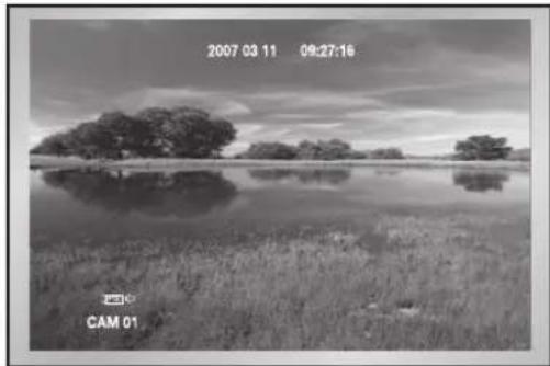
natural_image
Black-and-white landscape photo showing a calm lake with scattered trees and grass, no visible text or symbols.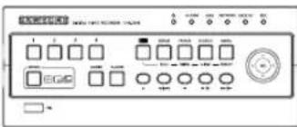
text_image
Control panel interface with labeled buttons and display indicators[SHR-2040]
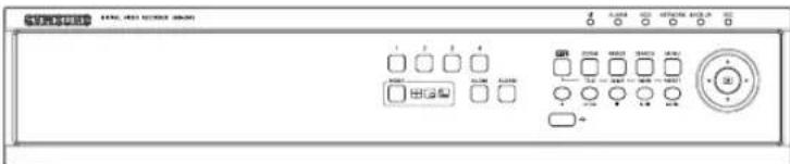
text_image
SAMSUNG 12320 12320 12320 12320 D A B C D E F G H I J K L M N O P Q R S T U V W X Y Z A B C D E F G H I J K L M N O P Q R S T U V W X Y Z[SHR-2041]

text_image
CD-Ru 1 2 3 4 DC-50 DC-50 DC-50 DC-50 DC-50 DC-50 DC-50 DC-50 DC-50 DC-50 DC-50 DC-50 DC-50 DC-50 DC-50 DC-50 DC-50 DC-50 DC-50 DC-50 DC-5 DC-5 DC-5 DC-5 DC-5 DC-5 DC-5 DC-5 DC-5 DC-5 DC-5 DC-5 DC-5 DC-5 DC-5 DC-5 DC-5 DC-5 DC-5 DC-5 DC-5 DC-5 DC-5 DC-5 DC-5 DC-1[SHR-2042]
- Press the PTZ button in Live Mode to cancel PTZ Camera Control Mode. After cancellation, the PTZ symbol on the screen will turn white from yellow while the PTZ button will lose its blue light.
Note
You cannot use the PTZ device device and remote control device at the same time, because of communication problems.
In PTZ control mode, DVR's PTZ mode is canceled when remote control mode is connected, and the remote control device is disconnected when the DVR changes to PTZ mode while controlling the DVR with a remote control device.
Refer to the remote control device manual on how to control the DVR's PTZ device in the remote control device.
When using the remote controller (SCC2000), direct camera control is available only for Samsung Protocol in the remote controller (refer to the SCC2000 user manual). If there is no PTZ control within the maximum 5 minutes in DVR, the PTZ mode is cancelled automatically. It is for PTZ control in the remote viewer while not controlling PTZ.
2
Basic Operation of PAN, TILT, & ZOOM
• PAN
Press the LEFT or RIGHT button in front SHR-2040/2041/2042 in PTZ Camera Control Mode to control PTZ Camera horizontally.
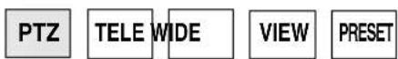
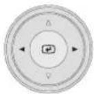
• TILT
Press the UP or DOWN button in front SHR-2040/2041/2042 in PTZ Camera Control Mode to control PTZ Camera vertically.
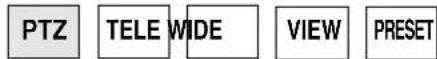

• ZOOM
Press the TELE/WIDE button in front SHR-2040/2041/2042 in PTZ Camera Control Mode to zoom in or out PTZ Camera.

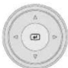
3 Preset Setup
● Records a certain position of PTZ Camera.
● Memorizes up to 20 PTZ Camera positions at the moment.
Note
For AD Protocol PTZ Camera, this memorizes only 7 Presets.
Caution
When using a remote control device (SCC2000), it is possible to control the camera with the remote control limited to the Samsung protocol. (refer to SCC2000 user manual) If there is no PTZ control for 5 minutes from the DVR, PTZ mode is automatically cancelled. This is to control PTZ with the remote viewer when there is no PTZ control.
- Press the Preset button in front of SHR-2040/2041/2042 in Single Screen PTZ Camera Control Mode to set up Preset.


text_image
Preset Camera Menu Exit● After Preset setup, press ENTER.

text_image
No. Position Name Del 1 2 3 4 5 6 7 8 Name PTZ Control Prev Next Exit- Move the cursor to right and press ENTER in PTZ Control Mode first. Then, press the "Enter" to run P/T/Z/ operation mode in the PIP screen and press the "Enter" again to cancel P/T/Z/ Motion Mode.
- Press Enter at the Position Name position to see Virtual Keyboard. Enter the type position name and press the "OK" to save the position and position name.

text_image
CAM_01 CapsLock Delete << Back Space OK Cancel- Press the "Del" to delete both Position and Position Name with the number.
- Click the Press Del √ on the top to delete all positions and position names in memory.
4
Camera Menu Setup
● Camera Menu is a menu supplied by PTZ Camera itself. This Menu sets up several conditions of PTZ Camera.
Note
Pan. or Samsung Protocol Camera only is authorized for Camera Menu setup.
- Press the Preset button in front of SHR-2040/2041/2042 in Single Screen PTZ Camera Control Mode to select Camera Menu.


text_image
Preset Camera Menu Exit
text_image
** MAIN MENU V2.0 ** CAMERA... VIDEO SET... PRESET... AUTO SET... OTHER SET...- Press the "Preset" button in front of SHR-2040/2041/2042 to return to the upper menu from camera menu.
5 Preset View
- Preset setup allows your movement to a certain saved position of PTZ Camera.
- Press the VIEW button in front of SHR-2040/2041/2042 in Single Screen PTZ Camera Control Mode to select Preset.
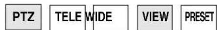

natural_image
Black-and-white landscape photo showing a calm lake with scattered trees and distant hills, no text or symbols visible.(For example, Samsung Protocol)
● Control the cursor until it reaches a preset position number that you want to move and you can check it in the right PIP Screen.

text_image
No. Position Name 1 2 3 4 5 6 7 8 Prev Next Exit6 Other View
- Press the "VIEW" button in front of SHR-2040/2041/2042 in Single Screen PTZ Camera Control Mode to supply PTZ Camera. This is a very special function.
Note
Samsung, Pan., Pel-P, or Pel-D Protocol PTZ Camera supports this function.
Samsung : Auto Pan / Scan / Pattern
● After you select a function, press Enter. Then the function will be checked and start running.
- If you select other function during the operation, the previous function will be unchecked and the current function will be checked.
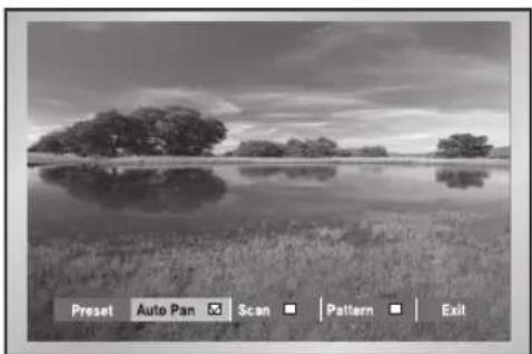
natural_image
Black-and-white landscape photo of a calm lake with scattered trees and reflections, no text or symbols visible.(For example, Samsung Protocol)
- If you put P/T/Z/ during the operation or enter the Preset Setup or Camera Menu Setup during the operation, the function in action will be suspended and unchecked.
- Restarting SHR-2040/2041/2042 system during the operation has no effect. The function continues its duty and remains checked.

natural_image
Abstract digital illustration of circuit board patterns and server racks (no text or symbols)Chapter 7 Recording
1 REC (Normal Recording)
- Pressing REC the button starts recording as set in the record mode. Then, REC LED lights on and a recording icon appears on the screen. During the recording in HDD, the front HDD LED blinks.
● During the normal recording, you can stop it by pressing the REC button. If the recording stops, REC LED lights out.
Warning
If the work that has to stop the recording(Time change, File delete, HDD connect/disconnect etc.) is performed during the recording, the current recording stops.
2
Schedule Recording
- While "Record Schedule" or "Schedule/Event recording" is selected in the Record Schedule menu, Schedule Recording automatically starts. Otherwise, Schedule Recording remains inactivated. During the Schedule Recording, Recording Icon appears on the screen. During the recording in HDD, the front HDD LED blinks.
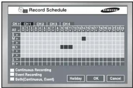
text_image
Record Schedule CH > CH 1 CH 2 CH 3 CH 4 All 0 1 2 3 4 5 6 7 8 9 10 11 12 13 14 15 16 17 18 19 20 21 22 23 S > M > T > W > T > F > S > H > Continuous Recording Event Recording Both(Continuous, Event) Holiday OK Cancel- If the Event Recording is selected, the recording starts at the every event. In this case, the channel's event recording setup is saved as setup in the event recording mode setup sub-menu (resolution, recording quality, recording ips, pre-event, post-event) of the event recording menu.
Note
Even in case of an event, Event Recording will not start unless Event Recording or Schedule/Event recording is selected in the Schedule Recording.
Warning
If the work that has to stop the recording(Time change, File delete, HDD connect/disconnect etc.) is performed during the recording, the current recording stops.
3 Event Recording
- Alarm Detection
Sensor operation mode in Alarm of Event Record menu shall be set to N.O (Normal Open) or N.C (Normal Close).
● Motion Detection
Motion detection in the Event Recording menu shall be set to On.
● Video Loss Detection
Video Loss in Event Record menu shall be set to On.
● Event Recording Mode
Sets the recording type when an event occurs. In particular, depending on PreAlarm Off or PostAlarm Off, PreAlarm or PostAlarm Recording is disabled respectively.
Warning
If the work that has to stop the recording(Time change, File delete, HDD connect/disconnect etc.) is performed during the recording, the current recording stops

natural_image
Abstract digital illustration of circuit board and server racks (no text or symbols)Chapter 8 Search and Play
Before Use
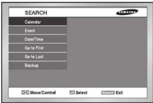
text_image
SEARCH Calendar Event Date/Time Go to First Go to Last Backup Move/Control Select Search Exit- Pressing the "SEARCH" button shows Search Menu on the screen as seen above.
- Calendar Search searches a video file by the use of a calendar at the desired time.
● Event Search searches a video file recorded by the occurrence of event.
● Date/Time Search searches a video file by the entering of a day and time.
- "Go To First" searches a video file from the oldest one.
- "Go To Last" searches a video file from the latest one.
● Backup Search searches backed-up video file.
- You can search for images on a USB HDD and USB memory. A USB CD/DVD and built-in CD are played as AVI backups on a PC.
1 Calendar Search

text_image
Calendar Search (Can Select 4 Channels) CH 1 CH 2 CH 3 CH 4 2007 01 Sun Mon Tue Wed Thu Fri 1 2 3 4 5 6 7 8 9 10 11 12 13 14 15 16 17 18 19 20 21 22 23 24 25 26 27 28 29 30 31 Cancel OK- Be sure to select both the channel and the date to search. And press the [OK] button to search for the desired time.
- Use a calendar to search the video file of desired time. Four channels in maximum are in the range of search.
- Select the channel up to 4 by the use of ◀, ▶ and Enter button. And then the date column will be displayed in thick blue when it has a video recorded in the channel.
- Use the ◀, ▶ button until you reach the Year / Month setup line and use both buttons and the "Enter" button to select Year/Month.
- If you select a day by the [Enter] button, a checkbox will appear on the right of the date number and the checkbox will be checked.
- Use the ▼ button until you reach the Time bar and move to the time you want with the ◀, ▶ button, and then press the Enter button to select a time.
- If you want to start the search, press the [OK] button. And press the [Cancel] button to move to the previous menu.
● You are able to search every 30 minutes.
2 Event Search

text_image
Event Search (Can Select 1 Event) CH 1 CH 2 CH 3 CH 4 No. Date / Time Event Mode First Prev Next Last Start Cancel- Searches Normal Recording, Schedule Recording, Alarm Recording, Motion Recording, and V.Loss(Video Loss) Recording by the time.
- You shall select a channel to search to see the event information of the channel.
- On the basis of event information for each channel, the system searches a video file for the event. Only one channel is allowed for video search.
- If you use both the [Enter] button and the ◀, ▶ button key to select a channel, the system will show the list of event for the selected channel only.
- After channel selection, you can use the ▲, ▼ [Enter] button to select an event out of the list. The checkbox on the left of the selected event number will be checked.
- If you want to start the search, use the ▼ button until you reach [START] and press the [Enter] button. If you want to cancel the search, move to the [Cancel] and press the [Enter] button. If you wish to view the event list of the next screen, select [NEXT] and press the [Enter] button and if you wish to view the event list of the previous screen, select [PREV] and press the [Enter] button.
3D
Date/Time Search
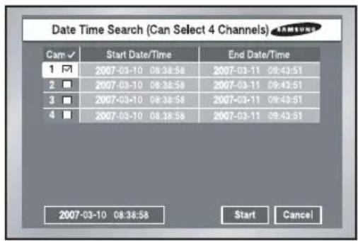
text_image
Date Time Search (Can Select 4 Channels) Cam ✓ Start Date/Time End Date/Time 1 ✓ 2007-03-10 08:38:58 2007-03-11 09:43:51 2 ✓ 2007-03-10 08:38:58 2007-03-11 09:43:51 3 ✓ 2007-03-10 08:38:58 2007-03-11 09:43:51 4 ✓ 2007-03-10 08:38:58 2007-03-11 09:43:51 2007-03-10 08:38:58 Start Cancel- Use the Date/Time information to search a video file at the time as you desire. Up to 4 channels can be searched at once.
- After you select a channel with the ▲, ▼, [Enter] button, the checkbox on the right of selected event number will be checked.
- Use the ▼ button until you reach the Search Time setup line. Press the [Enter] button to change the search time. Search Time change will be done by the Year/Month/Day/Hour/Minute/ Second unit with the ▲, ▼, button. For your convenience, you may hold on a key to change the value continuously.
- If you want to start the search, use the ▼ button until you reach [START] and press the [Enter] button. If you want to cancel the search, move to the [CANCEL] and press the [Enter] button.
- The time information, 2007-03-10 08:38:58 on the bottom left corner, represents the time when play starts.
Go to First Search

text_image
Go to First Search (Can Select 4 Channels) Cam ✓ Start Date Start Time 1 ✓ 2007-03-10 08:38:56 2 ■ 2007-03-10 08:38:56 3 ■ 2007-03-10 08:38:56 4 ■ 2007-03-10 08:38:56 Start Cancel- Searches the oldest one among recorded video files. Up to 4 channels can be searched at once.
- After you select a channel with the ▲, ▼, [Enter] button, the checkbox on the right of the selected channel number will be checked.
- Press the [Start] button want to start the search and to cancel. And press the [Cancel] button to cancel the search.
5G
Go to Last Search
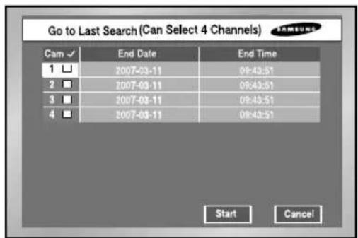
text_image
Go to Last Search (Can Select 4 Channels) Cam ✓ End Date End Time 1 □ 2007-03-11 09:43:51 2 □ 2007-03-11 09:43:51 3 □ 2007-03-11 09:43:51 4 □ 2007-03-11 09:43:51 Start Cancel- Searches the latest one among recorded video files. Up to 4 channels can be searched at once.
- After you select a channel with the ▲, ▼,[Enter] button, the checkbox on the right of the selected channel number will be checked.
- Press the [Start] button want to start the search and to cancel. And press the [Cancel] button to cancel the search.
- If you start Go To Last Search during recording, the system will search the video image right at the time of entering Search.
Backup

text_image
Backup Search (Can Select 1 Event) No. File/Filename 1 ☑ 20070302/1104 2 □ 20070303/1412 3 □ 20070304/1645 4 □ 20070304/1705 5 □ 20070304/1905 2007-03-02 11:04:34 Prev Next Start Cancel● First, select the backup device.
● Mark the data of device.
- Select the file name to backup, and the detail information of a file is displayed in the below.
● The [Previous] button shows the previous page.
● The [Next] button shows the next page.
● The [Start] button plays the desired file.
● The [Exit] button exits the menu.
Playback
- Press the PLAY/PAUSE button( ▶/10) to play the data recorded in HDD.
- If you used the SEARCH button for playback just before, the system would remember the information of the played channel until you click the PLAY/PAUSE button(▶/Ⅱ) again, then the system plays the previous channel.
If you press the PLAY/PAUSE button(▶/Ⅱ), the Search Menu will appear as far as you never tried the playback.
Note
Pressing the PLAY button(▶/II) does not affect the playback as far as the user stays in the MENU. Be sure to exit from the MENU to start the playback.
- Press the STOP button(■) to stop the playback. If you press the Playback/PAUSE button(▶/II) once more, the recording will resume from the point where the previous recording stops. When the data position reaches the end of HDD during the playback, the playback will be paused.

natural_image
Black-and-white photo of a young girl sitting outdoors with flowers and a glass, no visible text or symbols.● Definition Play Screen Mode
4 Split Screen

Single Screen

PIP Screen
6 Split Screen

9 Split Screen
① 4 Split Screen : If you select more than a channel, 4 Split Screen will appear.
② Single Screen: This appears when you select one channel in Search. If you press the [CH1\~CH4] button in the other split screen, the selected channel appears with the single screen. If you press the ZOOM button in the single screen, the selected area will be enlarged by twice. And you can move the zoom area by the use of direction key.
③ PIP Screen : If you press the Mode button while the single screen plays, PIP Screen will appear(The large screen displays the channel in play while the small screen on the bottom right corner displays a Live channel in PIP type). Use the UP and DOWN key to move small PIP screen (Live Channel) vertically. If you press the [ENTER] button, a blue bar will appear in the live screen and if you press the Channel button, you will be able to turn to the channel selected by the live screen.
④ 6 Split Screen : If you press the Mode button in the single screen, 6 split screen will appear. The single screen in playing is displayed at the top of right, and the 4 live screens are displayed at the bottom of left.
⑤ 9 Split Screen : If you press the Mode button in the 4 split screen, 9 split screen will appear. The 4-split screen in playing is displayed at the top of right, and 4 live screens are displayed at the bottom of left.
● Play at Faster Speed
If you press the LEFT or RIGHT button(◀/▶) during the playback, you will be able to see the screen at the x2, x4, x8, x16, x32, and x64 speed either forwardly or reversely.
- Viewing Still Screen
If you press the LEFT or RIGHT button(◀/▶) when the system paused, you will be able to see still screens forwardly or reversely.
During the reverse search, the interval between cuts becomes long depending on the recording specification.
● Audio On/Off
If you press the [Audio] button in other screen than 4 Split Screen(i.e. Single Screen, PIP Screen, and 9 Split Screen), you will be able to turn Audio of the playback channel on or off. In 4 Split Screen, Audio is not activated.
natural_image
Abstract digital illustration of circuit board patterns and a laptop with monitor (no text or symbols)Chapter 9 Smart Viewer
1 Introduction
Smart Viewer is a program that a general PC user is able to install SHR-2040/2041/2042 to his PC to monitor the video and audio data in the real time through network without going to the site where SHR-2040/2041/2042 is installed.
2 Feature
- Thanks to the transmission of video data compressed by the MPEG-4 Video Compression method, it can play the video images of good quality.
- Thanks to the G.726 Voice Compression method, it supplies the voice data of good quality. Use of armored MIC improves the quality of remote voice.
- Thanks to the transmission of video/audio stream through RTP(Real-Time Transport Protocol), the real-time video playback is excellent and multi-users' simultaneous connection does not affect the transmission speed in whole abruptly.
- Command & Control by RTSP(Real-Time Streaming Protocol) enables safety control through the network.
● Variable transport protocols are supported (TCP/IP, UDP(Unicast, Multicast)). - Connection is open to you at any time to monitor video and audio data by inputting IP Address only.
- You can not only perform real-time recording( *.dvr format) with User's PC whereas necessary during the monitoring but also convert recorded video files(*.dvr format) into frame unit images(JPEG format).
- Up to 3 Smart Viewer users are allowed to connect to a DVR simultaneously. (If the multicast is used, up to 6 users can connect.)
- With a Smart Viewer, you are allowed to connect to as many as 16 SHR-2040/2041/2042s to monitor them simultaneously.
● Smart Viewer is optimized in the resolution of 1024X768.
3
PC Specification(Recommendation)
- OS : Win2000, WinXP
● Recommendation : CPU Pentium 3, 1GHz or higher
RAM 256 MB or higher
VGA RAM 32Mb or higher
DirectX 8.1 or higher
Note
Depending on Recording Rate, Video Size, and user's PC specification set to SHR-2040/2041/2042, the number of Smart Viewer playback frame varies. For the detailed specification, refer to Appendix 4.
4
Smart Viewer Installation
Smart Viewer Installation
- Put a Smart Viewer Program CD in CD-ROM and open the "Smart Viewer" folder in the CD.

text_image
InstallCD File Edit View Favorites Tools Help Back Search Folders Address Install Go Smart Viewer Manuals 2 object(s) 0 bytes My Computer- Run the "Setup.exe" file.

text_image
InstallD File Edit View Favorites Tools Help Back Search Folders Address Install data1.cab data1.hdr data2.cab ikernel.ex_ layout.bin Setup.exe Setup.ini setup.inx 9 object(s) 10.6 MB My Computer- Click the "Next" button.

text_image
InstallShield Wizard Welcome to the InstallShield Wizard for SmartViewer 2.0 The InstallShield® Wizard will install SmartViewer 2.0 on your computer. To continue, click Next < Back Next Cancel- If you agree with Smart Viewer License, click "Yes".
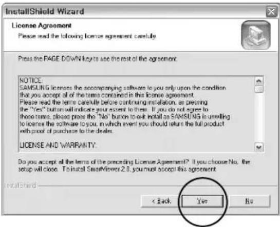
text_image
InstallShield Wizard License Agreement Please read the following license agreement carefully Press the PAGE DOWN key to see the rest of the agreement. NOTICE. SAMSUNG licenses the accompanying software to you only upon the condition that you accept all of the terms contained in this license agreement. Please read the terms carefully before continuing installation, or pressing the "Yes" button will indicate your extent to them. If you do not agree to these terms, please press the "No" button to exit install as SAMSUNG is unwilling to license the software to you, in which event you should return the full product with proof of purchase to the dealer. LICENSE AND WARRANTY. Do you accept all the terms of the preceding License Agreement? If you choose No. the setup will close. To install SmartViewer 2.0, you must accept this agreement. InstallShield < Back Yes No- Designate a folder to install Smart Viewer in it and click "Next".
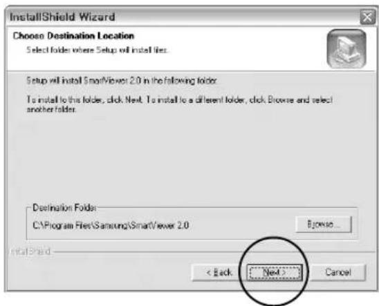
text_image
InstallShield Wizard Choose Destination Location Select folder where Setup will install files. Setup will install SmartViewer 2.0 in the following folder. To install to this folder, click Next. To install to a different folder, click Browse and select another folder. Destination Folder C:\Program Files\Samsung\SmartViewer 2.0 Browse... < Back Next > Cancel● The system proceeds with setup file installation and system setup.

text_image
InstallShield Wizard Setup Status SmartView 2.0 Setup is performing the requested operations. 100% InstallShield Cancel● Installation is complete. Click the "Finish" to terminate the installation.

text_image
InstallShield Wizard InstallShield Wizard Complete Setup has finished installing SmartView 2.0 on your computer. Finish Cancel5
Smart Viewer Program Execution
● Double-click the Smart Viewer icon in the background screen to run the program.

Smart Viewer Initial Screen
- Screen Description

text_image
Smart Viewer 2.0 for ProDVR CAM 01 No Signal CAM 02 No Signal DVR #:192.168.130.12 CAM 03 No Signal CAM 04 No Signal DVR #:192.168.130.12 CAM 05 No Signal CAM 06 2007.05.04.FR7 AM 04:52.21 DVR [] SAMSUNG DIGITAL Log Camera Connecting... DVR [] CameraCall... The Jul 23 15:31:07:007 Samsung Digital Vioio Recording System 1 2 3 4 5 6 7 8 9 10 11 12 13 14 15 16 +10 +1 01 +1 14① This is the button to enter the Search mode in which you can search and play remote the video file recorded in SHR-2040/2041/2042 and enter the Monitoring mode for real-time video monitoring.
② This button terminates or minimizes the program.
③ It displays the current date, day, and time.
④ This button is used for the connection with the preset DVR(SHR-2040/2041/2042) or site.
⑤ This screen shows the monitoring video.
⑥ These buttons select the window displays the event message and the window displays the connection condition of camera.
⑦ This window displays the event message from SHR-2040/2041/2042 in the real-time.
⑧ These buttons display the status of current channel.
⑨ These buttons adjust the audio volume and video brightness/contrast, and save the video file.
⑩ These buttons are used for PTZ related functions.
⑪ These buttons are used for screen split and Sequence Mode.
⑫ This button is used for the connection Callback.
⑬ This button is used for Favorite function when connecting to the site.
⑭ This button pops up the Setup Mode window to change Smart Viewer or SHR-2040/2041/2042 setup. (Refer to 9-30. Setup Mode.)
Monitoring Mode
● DVR(SHR-2040/2041/2042) / SITE Connection
- Select the name of DVR(SHR-2040/2041/2042) or site for connection and click the connection button.

text_image
DVR [216] DVR [216] DVR [219] DVR [87]Note
You can set the name, IP, and password of DVR (SHR-2040/2041/2042) for connection in the Setup mode. Also, the site setup which permits simultaneous connection to multi-DVRs (SHR-2040/2041/2042) is available in the Setup mode. You can connect up to 16 DVRs (SHR-2040/2041/2042) at once when connecting to the site.
◆ Connection Failure Cases
- Password Certification Failure

text_image
[Login DVR :] Password Error ○ Admin ○ User Password □ Save Password OK Cancel- In case of discord between the Network password set to SHR-2040/2041/2042 and the connection password set to Smart Viewer, a window pops up to induce retry of password input.
- Duplicate Admin User Connection

text_image
[Login DXR :] If you authenticate "ADMN", former "ADMN" session will be disconnected. ○ Admin ○ User Password □ Save Password OK Cancel- When the DVR that you want to connect to has been already occupied by an Admin user but you retry connection with the Admin privilege, the previously connected session is automatically disconnected.
Note
No more than 3 users, one Admin. authorized user and 2 User authorized users are allowed to access SHR-2040/2041/2042 simultaneously.(In the case of multicast, 5 User authorized users are allowable.)

Caution
Once occupied by 3 users( In the case of multicast, 6 users), SHR-2040/2041/2042 does not permit more connection.
● Monitoring Mode Connection Screen
text_image
Smart Viewer 2.0 for ProDVR CAM-03.C CAM-02.C 2007.03.07 16:35:28 DVR [0.0CAI-20] 192.16E 1.20 CAM-02.C CAM-04.C 2007.03.07 16:35:28 DVR [0.0CAI-20] 192.16E 1.20 2007.03.07 16:35:28 DVR [0.0CAI-20] 192.16E 1.20 2007.03.07 16:35:28 DVR [0.0CAI-20] 192.16E 1.20 2007.04.07 CAM-04.C CAM-04.C 2007.03.07 16:35:28 DVR [0.0CAI-20] 192.16E 1.20 1 2 3 4 5 6 7 8 9 10 11 12 13 14 15 16 2007.03.07 WED PM 10:39.28 DVR * SAMSUNG DIGITECT VANUHUA TECHNOLOGY Log Camera Connecting... [MR] Connected... PM Box PPTG 24:32:2007 Samsung Digital Video Recording SystemNote
When connecting with SHR-2040/2041/2042 in the 9-split mode setup, the setup, the setp is changed to the 4 split mode and 4 split screen is show After the connection, you can change it to the 9 split mode.

Caution
If you change the "Video size" or "Color Quality" from the setup tab of [Display Registration Information] while Smart Viewer is running, Smart Viewer will fall into an unexpected condition.
You should terminate the Smart Viewer first to change them.
● Mode Conversion Button
- This button converts the monitoring mode and the search mode.
● Time Information

- As soon as you are connected to SHR-2040/2041/2042, the current date, day, and time of SHR-2040/2041/2042 will be displayed.
- Otherwise, the current date, day, and time of your PC will be displayed.
- Connection Information

- As soon as you are connected to SHR-2040/2041/2042, the connection button will display connection status.
- If you click the connection button here, connection will be cancelled.

● Play Screen OSD Information
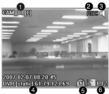
text_image
CAM_01 [C] 2007-02-07 08:20:45 DVR [static]:61.79.123.69 PTZ① Channel no., camera name, and video size will be displayed.
Video Size : (C)CIF / (N)Normal / (L)Large
② If the Video data of the current channel are recorded in your PC, REC mark is displayed.
③ Audio ON/OFF Button is displayed.
④ The name and IP address of SHR-2040/2041/2042 in connection are displayed.
⑤ The current channel alarm status is displayed.
⑥ The controllability of the current channel PTZ is displayed.
Note
③ Clicking the speaker icon turns the audio of channel on or off.
If you turn the audio of a SHR-2040/2041/2042 channel off, "Disable" will be displayed.
: Audio Disabled
* For the Audio on channel now, use the following audio button to adjust the volume and set the mute.
Note
⑤ the alarm or motion detection occurs at the channel of SHR-2040/2041/2042, which is set to alarm or motion detection, it is displays on the screen in the real-time with an icon.
⑥ If you connect and set up PTZ Camera in SHR-2040/2041/2042, PTZ controllability for the channel will be displayed.
* Select a channel capable of PTZ and use the PTZ button at the bottom to control PTZ. (Refer to the description of PTZ button.)
● Event Log Display Window

text_image
Camera Connecting... DVR [static] Connected... Not Feb 17 08:14:31 2007 Samsung Digital Video Recording System- Click the Log button to activate the log display window.
- It displays the event(alarm, user connection, and setup change) occurring at SHR-2040/2041/2042 in the real-time.
Note
[Event Message]
▶Connecting.. : Trying to connect to SHR-2040/2041/2042.
▶Connected.. : Succeeded connecting to SHR-2040/2041/2042.
▶Connection Failed : Failed in connecting to SHR-2040/2041/2042.
▶Disconnected.. : Finished connecting to SHR-2040/2041/2042.
▶ Setup(Remote) : SHR-2040/2041/2042 setup at Dvr Setup of Viewer changed.
▶ Setup Start / End (Local) : Start/Finish the Menu screen at SHR-2040/2041/2042.
▶ Video Loss CH[N] : Video Loss at the N channel of SHR-2040/2041/2042 encountered.
▶Time Change : Date/Time of SHR-2040/2041/2042 changed.
▶Load Factory Default : SHR-2040/2041/2042 System initialized.
▶Network Change : SHR-2040/2041/2042 Network setup changed.
▶System Shutdown : SHR-2040/2041/2042 System terminated.
▶Hdd Format : SHR-2040/2041/2042 HDD initialized.
▶Disk Full : No more space in SHR-2040/2041/2042 HDD.
▶Power Failure Recovery : SHR-2040/2041/2042 resumed after power failure.
▶ Backup Start/End/Fail/Stop : Backup at SHR-2040/2041/2042 started/finished/failed/stopped.
▶Network Traffic Busy : Data transport in the network is not smooth.
▶Access Denied(Limit Over) : Over connection.

Caution
When Time Change, Load Factory Default, Network Change, System Shutdown, or Hdd Format event occurs, Smart Viewer terminates the connection automatically.
● Camera connection Indication Window
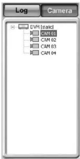
text_image
Log Camera DVR [static] CAM 01 CAM 02 CAM 03 CAM 04- Displays the connection condition of DVR and CAMERA in the list.
Note
[DVR Icon Color]
▶Successfully connected to SHR-2040/2041/2042, the icon turns yellow, otherwise, turns black.
[DVR Icon Color]
▶Connected to CAMERA for monitoring, the icon turns yellow.
▶Connectable, the icon turns blue, otherwise, turns black.
● Screen Split Selection Button
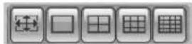
- Full Screen / Single / Quad / Nine-Split / Sixteen-Split Mode
- You can change the Split Mode of the screen under monitoring.
- Sequence Mode Button

- Changes the channel to be played at the preset interval.
- The sequence time interval can be set at the Setup Mode → Viewer Setup.
- In Single Mode : 1 → 2 → 3 → 4 → 1 (CH)
- In Quad Mode : 1,2,3,4 → 1,2,3,4 (CH)
- In Nine-Split Mode : 1,2,3,4 → 1,2,3,4(CH)
- In Sixteen-Split Mode : 1,2,3,4 → 1,2,3,4 (CH)
Note
If you connected with multi-DVRs(SHR-2040/2041/2042) through a site, the sequence will operate as follows.
- In Single Mode : DVR1:3CH →...→ DVR1:4CH → DVR2:1CH →...→ DVR1:1CH
- In Quad Mode : DVR1:1,2,3,4CH →...→ DVR2:1,2,3,4CH
- In Nine-Split Mode : DVR1:1,2,3,4CH → DVR2:1,2,3,4CH → ... DVR3:1,2,3,4CH
- In Sixteen-Split Mode : DVR1:1,2,3,4CH → DVR2:1,2,3,4CH → DVR3:1,2,3,4CH
● Monitoring screen condition Information / Selection Button
- Displays the Split or Monitoring condition of the screen in play.
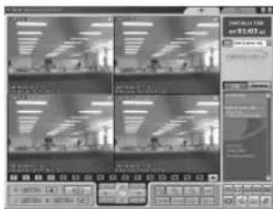
text_image
Screenshot of a video editing software interface showing four video thumbnails with Chinese text labels and playback controls.1 2 3 4 5 6 7 8 9 10 11 12 13 14 15 16 : When monitoring with Quad Mode
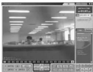
text_image
Screenshot of a software interface showing a workspace with ceiling lights and a data panel with statistics and graphs.1 2 3 4 5 6 7 8 9 10 11 12 13 14 15 16 : When monitoring with Single Mode

text_image
Screenshot of a software interface displaying a grid-based data visualization with icons and status bar at the bottom.Camera Off
Note
The number in the screen icon indicates the screen position in SmartViewer.
1 : The orange icon indicates the current channel is connected to a camera.
1 : The gray icon indicates the current channel is connected to a camera but not displayed in the screen.
: The black icon with a slash indicates the current channel is not connected to any camera.
- NEXT Button

- Click the NEXT(Mouse Left Button) to see the channel next to the current channel.
- In Single Mode : 1 → 2 → 3 → 4 → 1 (CH)
- In Quad Mode : 1,2,3,4 → 1,2,3,4 (CH)
- In Nine-Split Mode : 1,2,3,4 → 1,2,3,4 (CH)
- In Sixteen-Split Mode : 1,2,3,4 →1,2,3,4 (CH)
Note
If you connected with multi-DVRs(SHR-2040/2041/2042) through a site, the sequence will operate as follows.
- In Single Mode : DVR1:3CH →...→ DVR1:4CH → DVR2:1CH →...→ DVR1:1CH
- In Quad Mode : DVR1:1,2,3,4CH →...→ DVR2:1,2,3,4CH
- In Nine-Split Mode : DVR1:1,2,3,4CH → DVR2:1,2,3,4CH → DVR3:1,2,3,4CH ...
- In Sixteen-Split Mode : DVR1:1,2,3,4CH → DVR2:1,2,3,4CH → DVR3:1,2,3,4CH ...
- CALLBACK Button

- If you press CALLBACK, the CALLBACK window will be activated to receive messages.
- Receiving a message, Smart Viewer automatically tries to contact a DVR.
- In the event of Video Loss, Alarm, or Motion Detection, a message is received.
- You can select if the alarm is set on/off when it receives an event message.
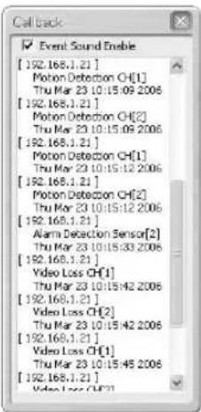
text_image
Event Sound Enable [192.168.1.21] Motion Detection CH[1] Thu Mar 23 10:15:09 2006 [192.168.1.21] Motion Detection CH[2] Thu Mar 23 10:15:09 2006 [192.168.1.21] Motion Detection CH[1] Thu Mar 23 10:15:12 2006 [192.168.1.21] Motion Detection CH[2] Thu Mar 23 10:15:12 2006 [192.168.1.21] Alarm Detection Sensor[2] Thu Mar 23 10:15:33 2006 [192.168.1.21] Video Loss CH[1] Thu Mar 23 10:15:42 2006 [192.168.1.21] Video Loss CH[2] Thu Mar 23 10:15:42 2006 [192.168.1.21] Video Loss CH[1] Thu Mar 23 10:15:45 2006 [192.168.1.21]- FAVORITE Button

- If you press FAVORITE, the FAVORITE window will be activated.
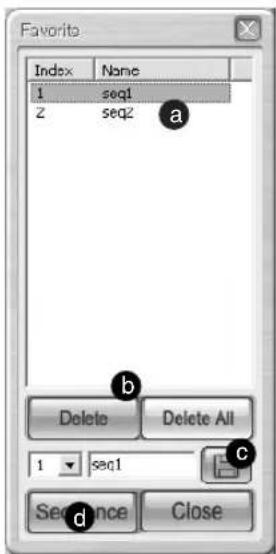
text_image
Favorite Index None 1-seq1 Z-seq2 a Delete Delete All 1-seq1 c Sequence Closea If you click the current FAVORITE, the cameras saved in the current setting value will be displayed in the screen.
b You may delete the selected FAVORITE or all FAVORITE setting values.
c You may set up a new FAVORITE number and name.
d Change FAVORITE at the set intervals.
Note
- The FAVORITE button is available only when you contact SITE.
- The FAVORITE information setting value is saved in the Config file even after you are away from the SITE.
- If you change the DVR list composing the SITE from Setup, the FAVORITE setting value will be initialized
● Video Recording Button

- If you select a channel in the playback and click the "Save" button, the video will be saved in a file format with the extension of *.dvr in a designated folder of your PC.
- The name of the directory in which an image will be saved, the file name, and the image save length shall be set up at the Setup Mode → Viewer Setup.
- The video length to be saved can be set from one minute to 10 minutes.
- The saved video can be played in the Local mode of Search mode.
- Click the button again to stop recording. However, manual suspension is prohibited for 10 seconds after recording started.
● Audio Volume Control Button

- You can control the audio volume of channel in the playback or set to mute for it.
- You can adjust the audio volume from 0 to +10.
● Video Brightness/Contrast Control button

- Select the channel in the playback and use the control button(+,-) to adjust the brightness or contrast of video.
- The default value is set to +5.
- You can adjust the brightness or contrast from 0 to +10.
- Press the button to recover the default value.
Note
The adjusted Audio volume, brightness, and contrast values will be saved in your PC and remain unchanged even if you terminate Smart Viewer and restart it.
● PTZ Camera Control Buttons
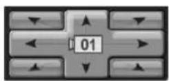
- Select a channel connected to PTZ Camera to control PTZ related functions.
- PAN Left / Right
- TILT Up / Down
- Diagonal Control
- The channel under PTZ control will be displayed in the center of the button.
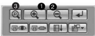
text_image
Screenshot of a software toolbar with numbered icons for menu, function, and view controls①② ZOOM IN / OUT
③ POWER ZOOM : Click P button to activate POWER ZOOM.
- POWER ZOOM is a function to zoom in or zoom out the video screen by clicking the screen.
- After POWER ZOOM is dominant, ZOOM IN / OUT will zoom in or out the video screen.
- POWER ZOOM Operation Procedure : Click POWER ZOOM → Select ZOOM IN or OUT → Click ZOOM IN or OUT zone in the video screen → ZOOM IN / OUT will be activated in the clicked zone.
Note
The PAN / TILT / ZOOM function is supported to all the cameras.
But, POWER ZOOM is supported only by Samsung Smart Dome Camera, and assured to the operation of TILT below 45°.

text_image
Screenshot of a software toolbar with icons for zoom, search, delete, and view controls labeled 1 to 4① PRESET
- If you press the PRESET button, a window for PRESET setup pops up.

text_image
Preset Index | Name | P 1 preset[1] a P 2 preset[2] Delete Delete All P 3 preset[3] c Closea If you click the current PRESET number and name, the camera will move to its position.
b You can delete the selected or all the PRESET setup values.
c You can set a new PRESET number and name.
Note
① The PRESET function is supported to all the cameras. You are allowed to set no more than 20 PRESET items. But, the AD Protocol camera can be set up to 7 PRESET items.
② AUTOPAN : The camera moves between starting and ending points.
③ SCAN : The camera moves circulating the preset positions.
④ PATTERN: The camera moves following the route that you have defined.
Note
The preset function is supported by all cameras. You can set up to 20 presets. But an active directory (AD) protocol camera can have 7 presets. The names of ②, ③, and ④ may vary depending on the camera vendor. And those functions may not be supported by some product.
- Samsung cameras support those functions.
- In case of Panasonic cameras, the names of AUTOPAN, SCAN, and PATTERN are as following: ② SEQUENCE ③ AUTOPAN ④ SORT.
- In case of PELCO cameras, the names of AUTOPAN, SCAN, and PATTERN are as following: ② FRAME SCAN ③ AUTO SCAN ④ PATTERN.
- The other cameras do not support those functions.
● Self Menu Setup of PTZ device
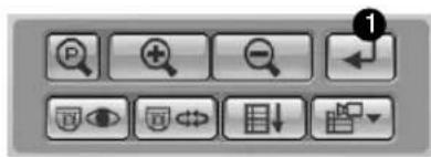
text_image
Screenshot of a software toolbar with function icons and labels, including zoom, delete, and rotate buttons① You can set the function menu in the PTZ camera.

text_image
MOMIN MENU VS. 500 CAMERA 1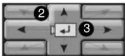
① This is a Menu screen supplied by the camera itself, seen from Viewer.
② Use the ↑/↓/←/→ button for the movement between menus.
③ This is a button for the role of Enter.
Note
The Camera Menu Setup function is supported by Samsung and Panasonic camera only.
Caution
As far as SHR-2040/2041/2042 uses the PTZ camera control functions, Smart Viewer can not control PTZ Camera.
The PTZ Camera control functions can be used by the user with Admin authority.
8 Search Mode
● The initial screen of search mode
- The search mode is divided into the remote mode to search and play the SHR-2040/2041/2042 video and the local mode to play *.dvr file saved in the directory designated by your PC.

text_image
Smart Views 2.0 for ProDVR SAMSUNG DIGITall everyone's Invited. SAMSUNG DIGITall everyone's Invited. SAMSUNG DIGITall everyone's Invited. SAMSUNG DIGITall everyone's Invited. 2007.04.11.TUE AM 01:03.05 DVR [LOCAL-20] SAMSUNG DIGITall everyone's Invited. 2007.02 SMTWTFSG 1/2/3 4/5/6/7/9/10 11/12/13/14/15/17 18/19/20/21/22/23/24 25/26/27/28/29/30 6 7 8 9 10 11 12 13① To change to the search mode for the remote control of video recorded in SHR-2040/2041/2042.
② To show the playback video.
③ To change to the remote mode for the transmission of video recorded in SHR-2040/2041/2042 through network.
④ To change to the local mode for the playback of *.dvr files recorded in your PC.
⑤ Calendar window to select "Year/Month/Day" for search.
⑥ To control the audio volume and video brightness/contrast.
⑦ To change the screen split.
⑧ Button for the Record / Convert File / Print / Setup functions.
⑨ To control the playback of searched video.
⑩ To display the next channel in order.
⑪ To change the channel and DVR or renew the calendar window and Time Line.
⑫ Timeline to display the time information of search date recorded in SHR-2040/2041/2042.
Note
- When connecting to the site, select a DVR to search in the camera connection list.
- When connecting as a user, you are denied to access the search mode.
● DVR(SHR-2040/2041/2042) Selection/Change by contacting SITE
- Same as "DVR(SHR-2040/2041/2042)/SITE Connection" of the monitoring mode.

text_image
Site [0] Site [0] DVR [160_2040] DVR [20] DVR [213] DVR [220]● DVR(SHR-2040/2041/2042) Selection/Change by contacting SITE
- Select SHR-2040/2041/2042 from the Contact list.
- SHR-2040/2041/2042 turns black if contacted with the ADMIN authority and turns gray if contacted with the USER authority.
- Without the ADMIN authority, search is not accessible.

- Remote Mode
- This mode transfers the video data recorded in SHR-2040/2041/2042 by network for the playback.
- Up to 4 channels are allowed for simultaneous search and playback.
- The video information at the time indicated by the timeframe will be displayed in the playback screen.

When clicking, it changes to the remote mode.

text_image
Smart Power 2.0 for PdCVR AM 01:34 05.04 05.04 05.04 05.04 05.04 05.04 05.04 05.04 05.04 05.04 05.04 05.04 05.04 05.04 05.04 05.04 05.04 06.12 06.12 06.12 06.12 06.12 06.12 06.12 06.12 06.12 06.12 06.12 06.12 06.12 06.12 06.12 06.12 06.12 07.12 07.12 07.12 07.12 07.12 07.12 07.12 07.12 07.12 07.12 07.12 07.12 07.12 07.12 07.12 08.12 08.12 08.12 08.12 08.12 08.12 08.12 08.12 08.12 08.12 08.12 08.12 08.12 08.12 08.12 08.12 09.12 09.12 09.12 09.12 09.12 09.12 09.12 09.12 09.12 09.12 09.12 09.12 09.12 10.12 10.12 10.12 10.12 10.12 10.12 10.12 10.12 10.12 10.12 10.12 10.12 10.12 10.12 10.12 10.12 11.12 11.12 11.12 11.12 11.12 11.12 11.12 11.12 11.12 11.12 11.12 11.12 11.12 11.12 11.12 11.12 12.12 12.12 12.12 12.12 12.12 12.12 12.12 12.12 12.12 12.12 13.12 13.12 13.12 13.12 13.12 13.12 13.12 13.12 13.12 13.12 13.12- Calendar Window
text_image
2007. 02 S M T W T F S 1 2 3 4 5 6 7 8 9 10 11 12 13 14 15 17 18 19 20 21 22 23 24 25 26 27 28- If the video data in on-line SHR-2040/2041/2042 is recorded, the date turns red.
- If you click the date in red, the saved video information is displayed.
- The currently selected date will be marked with a thick red box.
- ◀: Moves to the previous month.
- ▶ : Moves to the next month.
● Audio Volume Control, Video Brightness/Contrast Control Buttons
- Same as the control function of Monitoring Mode
● Screen Split Selection Button
- Full Screen / Single / Quad / Nine-split/ Sixteen split mode
Note
In the remote mode, Nine-split Mode is not available and in the local mode, Quad, Nine split Mode is not available.
● Video Save(Backup) / Video Conversion / Print / Setup
① Video save button
:During the playback(Play/Reverse Play/Fast Forward/Fast Backward),
- If you select a channel in the playback and click the SAVE button, the video is saved in a file format with the extension of *.dvr in a designated folder of your PC.
- The directory in which an image will be saved, the file name, and the video length to be saved can be set at the Setup Mode → Viewer Setup.
- The video length to be saved can be set from one minute to 10 minutes.
- Click the button again to stop recording. However, manual suspension is prohibited for 10 seconds after recording started.
Backup Button
- If not playback(Stop), the video save button performs the backup function.
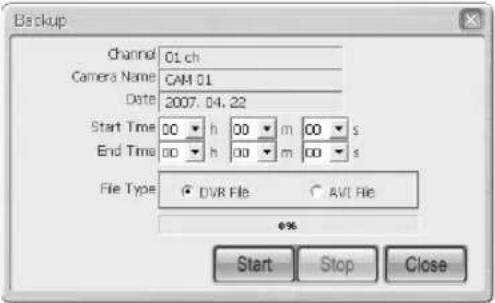
text_image
Backup Channel 01.ch Camera Name CAM 01 Date 2007.04.22 Start Time 00 h 00 m 00 s End Time 00 h 00 m 00 s File Type DVRI File AVI File 6% Start Stop Close- If the save button is pressed, the window for backup pops up.
- Set a Start/End tome for backup and select a file format to save.
- The backup starts when the "Start" button is clicked. The backup file is saved according to the setting route; Setup → Viewer Setup → Video Recording → Video Location.
- To stop the backup, click the "Stop" button.
Note
Video saving in the remote mode is available only when the Play/Reverse Play/Fast Forward/Fast Backward button remains pressed down.
The backup function in the remote mode is available at the Stop status. In the case of avi backup, you need the divx codec for playing saved files. The divx codec can be found at www.divx.com.
② File Converting Button
- This function converts *.dvr files into “*.jpg” files.

text_image
Convert DVD File To... DVD File ○ JPG Format ○ AVI Format Status: Start Stop Close- Click the "Open" button to select a *.dvr file to be converted.
- Select the JPEG Frame or AVI Video.
- If the JPEG Frame is selected, the file is converted into the “*.jpg” file by clicking the “Start” button. The converted “*.jpg” file is saved according to the setting route Setup → Viewer Setup → File Converting → Jpeg Location.
- If the AVI Video is selected, the file is converted into the “*.avi” file by clicking the “Start” button. The converted “*.avi” file is saved according to the setting route Setup → Viewer Setup → File Converting → AVI Location
- Press the "Start" button to convert it to a *.Jpg file. Press Setup → Viewer Setup → File Converting to save the converted *.jpg file.
- Click the Stop button to pause the file conversion.
③ Print
- This function outputs the screen zone of the playback video which is now being displayed.
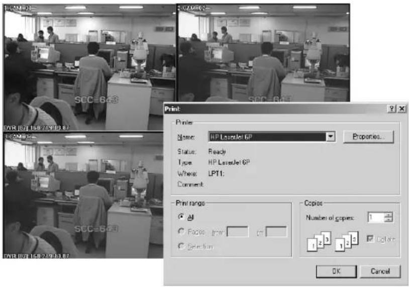
text_image
HBMDDI SCC-6.43 DVR 0/71.158.7.9.13.87 SCC-6.43 Print Printer Name: HP LaserJet 6P Status: Ready Type: HP LaserJet 6P Where: LPT1; Comment: Print range ✓ Copy: from ✓ Selection Copies Number of copies: 1 1 2 3 1 2 3 Color OK Cancel④ Setup Mode Button
- This button pops up the setup mode window.
- Play Buttons
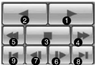
text_image
Grid of numbered UI icons with arrows pointing to each cell, likely representing media control or navigation buttons.① Play : Play
② Reverse Play : Reverse Play
③ Stop : Stop
④ Fast Forward : Faster Play
⑤ Fast Backward : Faster Reverse Play
⑥ Step Forward : Forward playback per second.
⑦ Step Backward : Reverse playback per second.
⑧ Go to First : Playback of the first image in the time Line
⑨ Go to Last : Playback of the latest(last) image in the time Line
Note
During the play(Play/RevPlay/FF/FB), disconnection or change to the both monitoring mode and local mode is not permitted. Click the Stop button first before the change.
- Time Line
- Displays the time information of video in SHR-2040/2041/2042 selected on the calendar window. - The normal mode indicates the time information of 24 hours while the Extension mode indicates the time information every 2 hours.

text_image
CAM 01 CAM 02 CAM 03 CAM CAMER05 CAMERA06 CAMERA07 CAMERA08 19:52:37 2 3[ Normal mode ]
① The channels being displayed in the playback screen will be activated in the white background.
② Time Line : The time information of video recorded in SHR-2040/2041/2042.
③ Time Bar : Displays the current time of video being displayed in the playback screen.
Note
Double click the area closed by the time bar to change to the zoom in mode. One column of time line represents an hour.
Time Line turns Green(Normal), Red(Panic), Orange(Alarm), Blue(Motion), Yellow(Schedule), or Purple(Video Loss) depending on the recording condition.
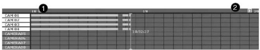
text_image
CAM 01 CAM 02 CAM 03 CAM 04 CAMERA05 CAMERA06 CAMERA07 CAMERA08 19:52:07 19:52:07 19:52:07 19:52:07 19:52:07 19:52:07 19:52:07 19:52:07 19:52:07 19:52:07 19:52:07 19:52:07[Zoom In Mode]
① Displays the time line one hour ago.
② Displays the time line one hour later.
Note
Double click again the area closed by the time bar to change to the normal mode. One column of time line represents 5 minutes.
Time Line turns Green(Normal), Red(Panic), Orange(Alarm), Blue(Motion), Yellow(Schedule), or Purple(Video Loss) depending on the recording condition.
- Next Button

- Changes the channel as the Next button does in the monitoring mode.
Note
During the video playback(Play/RevPlay/FF/FB), the channel change is not available.
- Reload Button

- Updates the record time information in the calendar window and time line.
- Local Mode
- Plays *.dvr file saved in the directory of your PC by the Record function.
- You can search and play only one channel.
- You are allowed to access it regardless of connecting with SHR-2040/2041/2042.
- Other functions than the calendar display function are as same as those of the remote mode.
- The time information of LocalFile will be displayed at the first channel position in the time line together with the file name.

: Selects a file to be played in the file selection window and changes to the local mode.
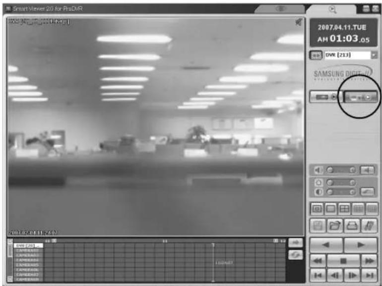
text_image
Smart Viewer 2.0 for ProDVR 2007.04.11.TUE AM 01:03 .05 DWR [213] SAMSUNG DIGITAL 2007-02-01(19:23) DWR F261 C:\WINDOWS\WINDOWS\CSP\WINDOWS\CSP\WINDOWS\CSP\WINDOWS\CSP\WINDOWS\CSP\WINDOWS\CSP\WINDOWS\CSP\WINDOWS\CSP\WINDOWS\CSP\WINDOWS\CSP\WINDOWS\CSP\WINDOWS\CSP\WINDOWS\CSP\WINDOWS\CSP\WINDOWS\CSP\WINDOWS\CSP\WINDOWS\CSP\WINDOWS\CSP\WINDOWS\CSP\WINDOWS\CSP\WINDOWS\CSP\WINDOWS\CSP\WINDOWS\CSP\WINDOWS\CSP\WINDOWS\CSP\WINDOWS\CPP\WINDOWS\CPP\WINDOWS\CPP\WINDOWS\CPP\WINDOWS\CPP\WINDOWS\CPP\WINDOWS\CPP\WINDOWS\CPP\WINDOWS\CPP\WINDOWS\CPP\WINDOWS\CPP\WINDOWS\CPP\WINDOWS\CPP\WINDOWS\CPP\WINDOWS\CPP\WINDOWS\CPP\WINDOWS\CPP\WINDOWS\CPP\WINDOWS\CPP\WINDOWS\CPP\WINDOWS\CPP\WINDOWS\CPP\WINDOWS\CPP\WINDOWS\CPP\WINDOWS\CPP\WINDOWS\CFP\WINDOWS\CFP\WINDOWS\CFP\WINDOWS\CFP\WINDOWS\CFP\WINDOWS\CFP\WINDOWS\CFP\WINDOWS\CFP\WINDOWS\CFP\WINDOWS\CFP\WINDOWS\CFP\WINDOWS\CFP\WINDOWS\CFP\WINDOWS\CFP\WINDOWS\CFP\WINDOWS\CFP\WINDOWS\CFP\WINDOWS\CFP\WINDOWS\CFP\n2007.04.11.TUE AM 01:03 .05 DWR [213]Note
Only the *.dvr file saved by the audio activation can be played in the local mode.

text_image
9 SoSetup Mode
- Initial Screen

text_image
Setup DVR Setup Viewer Setup Site Setup S/W Version Video Recording Naming Camera No. + Serial No. Camera No. + Date Location C:\Program Files\WSamsung\Smart Viewer 2.0 for ProDVR W... Recording Time 10 Min. 1 Min. 10 Min. File Converting [JPEG] Location C:\Program Files\WSamsung\Smart Viewer 2.0 for ProDVR W... [AV3] Location C:\Program Files\WSamsung\Smart Viewer 2.0 for ProDVR W... Sequence Time 5 Sec. 5 Sec. 30 Sec. OSD Display OSD Enable Auto Connection Auto Connection Enable DVIs/Site List Event Sound Sound Enable Event Sound Time Esec. Callback Connection Port(UDP) 7900 Language English Action Sequence Close① Button to select items for DVR Setup, Viewer Setup, Site Setup, and S/W Version setup.
② It shows what the selected Setup item can set up in detail.
③ button to terminate the setup window.
④ Button to save the information revised in the setup window, remark the information prior to such a revision, or terminate the setup window.
- Setup Item Selection Button

text_image
DVR Setup Viewer Setup Site Setup SW Version- It is used for the selection of each setup item.
- It is composed of 4 items-DVR Setup, Viewer Setup, Site Setup, and S/W Version.
- DVR Setup : Allows you to change the remote menu setup items of SHR-2040/2041/2042.
- Viewer Setup : Allows you to set the various kinds of item concerning the operation of Smart Viewer.
- Site Setup : Allows you to set SHR-2040/2041/2042 information, that is SHR-2040/2041/2042 name, IP Address, ID, and Password that you are going to contact through Smart Viewer or registers all the registered SHR-2040/2041/2042s at a site for control.
- S/W Version : Shows the current version of Smart Viewer, system requirement, and the System S/W version of on-line SHR-2040/2041/2042 and upgrades SHR-2040/2041/2042 System S/W remotely.
- Save/Cancellation of Revised Information

- Click the [Apply] button to save the information revised in the setup window and click the [Cancel] button to display the information before such a revision.
- Closing the setup window
- Click the [X] icon on the top of right corner in the setup window or click the [Close] button to close the setup window.
- If more than one setup item have been revised before you close the setup window, the following message box pops up. If you press OK, the revised information will be saved, closing the setup window but if you press CANCEL, the revised information will be flown away, closing the Setup window.
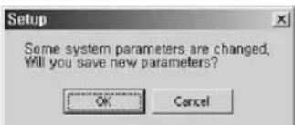
text_image
Setup Some system parameters are changed, Will you save new parameters? OK CancelDVR Setup

- Click the [DVR Setup] button for DVR Setup.
- You can change remotely the setup items of SHR-2040/2041/2042 Menu, being connected with Smart Viewer.
- DVR Setup is composed of 5 items; System, Camera/Audio, Monitoring, Recording, and Network.
Note
- You are authorized with access to DVR Setup in an Admin authority only.
- The button will not be activated if you are connected to SHR-2040/2041/2042 as a user or unconnected.

text_image
Setup DVR Setup Viewer Setup Site Setup SW Version System Camera Monitoring Recording Network Information Password Date/Time Language Storage Setup Remote Dev System Information System Information Software Version 03.0JE-K1.63-V2.19_0708161152 Broadcast Format PAL_ Mac Address 00.16.6C 00:37:8A① Among more than one SHR-2040/2041/2042 that is connected now, the name of SHR-2040/2041/2042 connected in the Admin authority will be listed. Depending on connecting to a SHR-2040/2041/2042 or the site, the name of SHR-2040/2041/2042 or the name of SHR-2040/2041/2042 connected in the Admin. Authority among those composing the site will be listed. You can select one to set SHR-2040/2041/2042 Menu.
② To display the setup menu for selected SHR-2040/2041/2042.
● Detailed DVR Setup Items
① System
- Information
Information shows the information on on-line SHR-2040/2041/2042.

text_image
Setup DVR Setup Viewer Setup Site Setup S/W Version DVR System Camera Monitoring Recording Network Information Password Date/Time Language Storage Setup Remote Dev System Information Software Version 83.03E-K1.53-V2.18_070615152 Broadcast Format PAL Mac Address 60.16.90:80.37.6ANote
For the detailed items of DVR Setup, refer to Chapter 5.
- Admin Password
You can change the Admin password related settings for control of DVR.
- User Password
You can change the user password related settings for control of DVR.

text_image
Setup DVR Setup Viseer Setup Site Setup SW Version OK System Camera Monitoring Recording Network Information Password Data/Time Language Storage Setup Remote Dev System Password Admin Password New Password: ******** Password Link: On Off Record Link: On Off User Password User Setup: User 1 New Password: ******** User Author A: As Search Backup PTZ Translation User Password
Caution
System Password shall be composed of numeric only, up to 8 digits.
Note
- The Delete key and the combination of Ctrl+C or Ctrl+V in the keyboard are not supported at the System Password input.
- Use the BACKSPACE key to delete the contents.
Note
Default System Password is set to 4321.
- Date/Time Data/Time is used to set the information of Date, Time, Format, and DST for on-line SHR-2040/2041/2042.

text_image
Setup DVR Setup Viewer Setup Site Setup S.W. Version OK System Camera Monitoring Recording Network Information Password Date/Time Language Storage Setup Remote Dev Date/Time Setup Date Time Current System Date: 2007-9-4 Current System Time: 06:11:41 Power Hours Clock 1.0 1.5 1.0 Hour 4min 8sec 30 AM Display Format Date: YYYY-MM-DD Time: 24 Hours DIST Month - Hour - Day - Hour Start: Month: Last: Next: End: October: Last: Next: Next: Add... Remove... Browse...Note
- If you change the Data/Time value, SHR-2040/2041/2042 automatically cuts the connection with Smart Viewer to apply the new time setup.
- Upon completing the new time setup for SHR-2040/2041/2042, you are permitted to resume the connection with the Smart Viewer.
- But, Display Format or DST can be set without the disconnection.
- Language
Language sets the language in which on-line SHR-2040/2041/2042 will be expressed

text_image
Setup DVR Setup Viewer Setup Site Setup S&W Version DWG System Camera Monitoring Recording Network Information Password Date/Time Language Storage Setup Resume Dev System Language Language English French German Spanish Italian Chinese Russian Korean Polish Japanese Dutch Portuguese Microsoft Internet ExplorerNote
The change of language by the system language results in the change of language expression setup of SHR-2040/2041/2042. In short, the language setup of Smart Viewer does not change.
Language specification to be supported is subject to change later.
- Storage Setup
It displays the information of the HDD that is contained in your DVR.
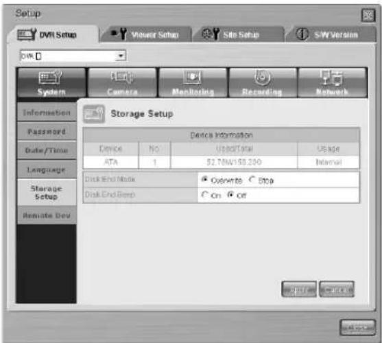
text_image
Setup DVR Setup Viseer Setup Site Setup S/W Version System Camera Monitoring Recording Network Information Password Date/Time Language Storage Setup Remote Dev Storage Setup Device Information Device No UpsetTotal Upgrade ATA 1 2.70NAV/0.200 Internal Disk End Node ○ Overwrite ○ Stop Disk End Deep ○ On ○ Off- Remocon (Remote Control Device)
Remocon can set the remote control device installed to SHR-2040/2041/2042.
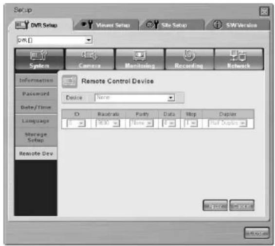
text_image
Setup DVR Setup Viewer Setup Site Setup SW Version OK System Camera Monitoring Recording Network Information Password Date/Time Language Storage Setup Remote Dev Remote Control Device Device: None ID Risobrate Parity Data Stop Duplex 5000 None 6 1 Soft Duplex OK Cancel OK CancelNote
If you install the remote control device to the main body of SHR-2040/2041/2042 and activate the setup, PTZ control is not available in the Viewer.
② Camera
- Config.
Config. sets Video, Audio On/Off, Camera Title, and Auto Sequence Time for each channel of on-line SHR-2040/2041/2042.

text_image
Setup DVR Setup Viewer Setup Site Setup SW Version 0% 0% System Camera Monitoring Recording Network Camera Config PTZ device Camera Config Cam Video Audio Title Auto Seq 1 On ✓ CAM 01 08 2 On ✓ CAM 02 5 sec 3 On ✓ CAM 03 5 sec 4 On ✓ CAM 04 5 sec OK OK OK OK
Caution
- Only English is supported for the title. If you type in and apply the title in your native language, warning message pop sup to ask your retyping.
- The title should be composed of no more than 15 digits.
- If you leave the title blank and apply it, Warning message pops up to ask your retyping.
Note
- The Delete key and the combination of Ctrl+C or Ctrl+V in the keyboard are not supported for title input.
- Use the BACKSPACE key to delete the contents.
- PTZ device
It sets Camera ID, Protocol, Baud Rate, Parity, Data Bit, Stop Bit, and Serial Mode when connecting the dome camera to all the channels.
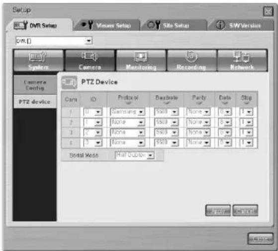
text_image
Setup DVR Setup Viewer Setup Site Setup SW Version OK System Camera Monitoring Recording Network Camera Config PTZ device PTZ Device Cam ID Protocol DAudrate Parity Date Stop 1 0 Samsung None 0 1 2 1 None None 0 1 3 2 None None 0 1 4 5 None None 0 1 Serial Mode: Hall Options OK Cancel Cancel③ Monitoring
- Monitoring
It sets both the event monitoring and OSG display of the live mode.
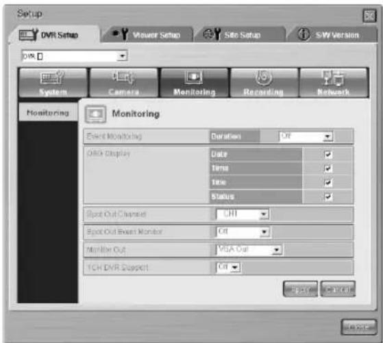
text_image
Setup DVR Setup Viewer Setup Site Setup S-W Version System Camera Monitoring Recording Network Monitoring Event Monitoring Duration Off Display Date Time Title Status Spot Out Channel CHI Spot Out Event Monitor Off Monitor Out VISA Out TCH DVR Support Off④ Recording
- Rec. Mode
It sets the Video Size, Quality, and Rate values during the recording by the setting the recoding ON/OFF for the related channel in the live mode.
NTSC PAL

text_image
Setup DNR Setup Vineac Setup Site Setup SW Version File: System Camera Monitoring Recording Network Record Mode Event Record. Video Size Alarm Record. Motion Record. Video Loss RECORD MODE Cam Mode Quality Rate 1 ✓ Standard 15.00 2 ✓ Standard 15.00 3 ✓ Standard 15.00 4 ✓ Standard 15.00 Video Size HARDENO OK Cancel Help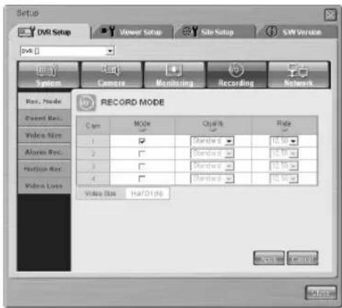
text_image
Setup DVD Setup Vener Setup Site Setup SW Version System Camera Monitoring Recording Network Rev. Mode Event Mode Video Rate Alarms Rate Position Rate Video Loss RECORD MODE Cam MOLE Quality Rate 1 ✓ Standard 10.00 2 ✓ Standard 10.00 3 ✓ Standard 10.00 4 ✓ Standard 10.00 Video Rate HaTOD (A) OK CancelNote
Full D1(L) Video Size does not support 15.00ips, 10.00ips (NTSC) / 12.50ips, and 8.33ips(PAL) Rate.
- Video size Rec.
Sets the Video size. The Video size being set in the menu affects to the ips setup of Rec. Mode and Event Rec.
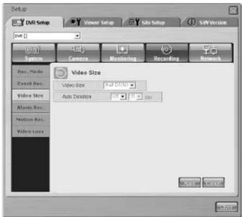
text_image
Setup DVR Setup Vineer Setup Site Setup S&W Version DVR System Camera Monitoring Recording Network Rec. Mode Event Rec. Video Size Alarms Rec. Prediction Rec. Video Sets Video Size Video Size (bit: 100) Auto Direction Add... Remove... Add... Add... Add... Add...Note
Full D1(L) Video Size does not support 15.00ips, 10.00ips (NTSC) / 12.50ips, and 8.33ips(PAL) Rate.
- Event Rec.
It sets the Video Size, Quality, Rate, Pre Alarm, and Post Alarm values to be recorded when an event occurs.
NTSC
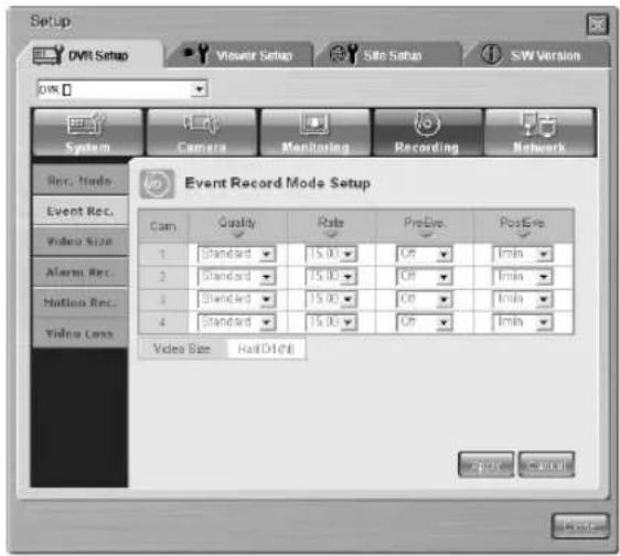
text_image
Setup DVD Setup Viewer Setup Site Setup SW Version WIN System Camera Monitoring Recording Network Rec. Mode Event Rec. Video Size Alerts Rec. Hotlines Rec. Video Lens Event Record Mode Setup Cam Quality Rate PreEye PostEye 1 Standard 15.00 Off Inmin 2 Standard 15.00 Off Inmin 3 Standard 15.00 Off Inmin 4 Standard 15.00 Off Inmin Video Size HallD1(8) OK CancelPAL
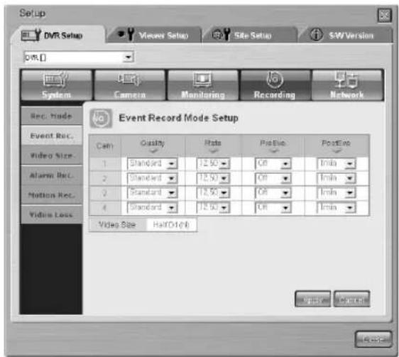
text_image
Setup DVR Setup Viewer Setup Site Setup SW Version DVR System Camera Monitoring Recording Network Rec. Mode Event Rec. Video Size Alerts Rec. Motion Rec. Video Loss Event Record Mode Setup Cam Quality Rate Positive Positive 1 Standard 12.50 GB - Min 2 Standard 12.50 GB - Min 3 Standard 12.50 GB - Min 4 Standard 12.50 GB - Min Video Size Half-Dt(D) Output SelectionNote
Full D1(L) Video Size does not support 15.00ips, 10.00ips(NTSC) / 12.50ips, and 8.33ips(PAL) Rate.
- Alarm Rec.
It sets the information necessary for the alarm recording.
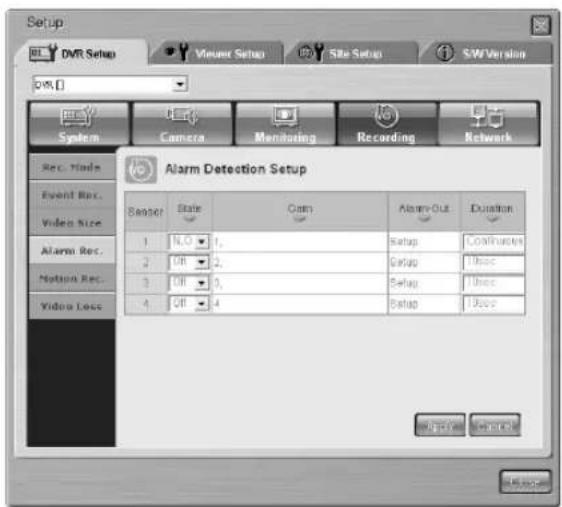
text_image
Setup DVR Setup Viewer Setup Site Setup SW Version OK System Camera Monitoring Recording Network Rec. Mode Event Rec. Video Size Alarm Rec. Motion Rec. Video Loss Alarm Detection Setup Sensor State Cam Alarm-Out Duration 1 N,O 1, Setup Contributions 2 Off 2, Setup 100cc 3 Off 3, Setup 100cc 4 Off 4, Setup 100cc OK Cancel Cancel OKNote
More than one camera should be selected to apply the alarm.
- Motion Rec.
It sets the information necessary for the recording by the motion Detection.

text_image
Setup DVR Setup Viewers Setup Site Setup S/W Version DVR System Camera Monitoring Recording Network Misc. Mode Event Box. Video Size Acceler Box. Motion Rec. Video Lock Motion Detection Setup Case MID Status Sensitivity Alarm Out Duration 1 0 Setup 1/2/3 2 0 Setup 1/2/3 3 0 Setup 1/2/3 4 0 Setup 1/2/3 5 Setup 1/2/3 6 Setup 1/2/3 7 Setup 1/2/3 8 Setup 1/2/3- Video Loss
Video Loss sets up the information on how to inform the user of Video Loss of SHR-2040/2041/2042.
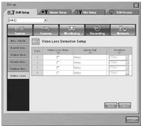
text_image
Setup DVR Setup Visual Setup Site Setup SUV Version OK [] System Camera Monitoring Recording Network Rev. Mode Event Ret. Video Size Alarm Ret. Motion Ret. Video Loss Video Loss Detection Setup Cam Video Loss Status Alarm-Out Duration 1 Setup User 2 Setup User 3 Setup User 4 Setup User Active Cancel⑤ Network
- Password
It sets the password for Admin and User when connecting with SHR-2040/2041/2042 through the network in Smart Viewer.
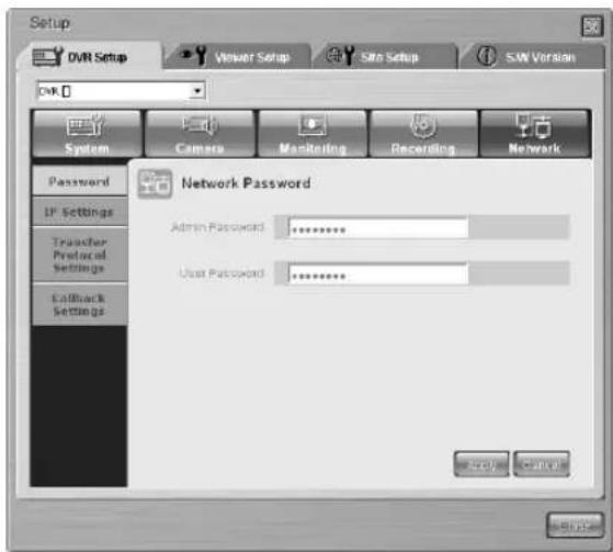
text_image
Setup DVR Setup Viewer Setup Site Setup S.W. Version DVR System Camera Monitoring Recording Network Password IP Settings Transfer Protocol Settings Callback Settings Network Password Admin Password: ********** User Password: ********** OK Cancel Cancel
Caution
- Network password should be composed of numeric and it can be input up to 8 digits. - If you leave password blank and apply it, a warning message pops up to ask your retyping.
Note
- The Delete key and the combination of Ctrl+C or Ctrl+V in the keyboard are not supported to the network password input.
- Use the BACKSPACE key to delete the contents.
Note
- Default Admin Password is set to 4321.
- Default User Password is set to 4321.
- IP Settings
It sets the network connection method of SHR-2040/2041/2042.
SHR-2040/2041/2042 supports the connection with Static IP, Dynamic IP, and ADSL(PPPoE). It can set the network bandwidth. Adjust the bandwidth to the network condition in which SHR-2040/2041/2042 is connected.
It sets the IP Address, Gateway, Subnet Mask, and DNS. Input both ID and password of the sub scriber for ADSL.
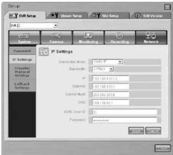
text_image
Setup DVR Setup Vinaer Setup Site Setup S.W. Version DVR System Camera Monitoring Recording Network Password IP Settings Transfer Protocol Settings Callback Settings IP Settings Connection Mode: Static IP Bandwidth: 2 Mbps IP: 192.168.130.12 Gateway: 192.168.130.1 Terminal Mask: 255.255.265.6 DNS: 168.126.83.1 ADBE User ID: IP Password: ******** OK CancelCaution
- Be sure to inquire the network manager before you input Network IP, Gateway, Subnet Mask, and DNS.
- Both ADSL ID and Password can be input up to 40 digits of alphabets, numbers, and symbols without discrimination.
● Transfer Protocol
- You can change the transfer protocol setting value. The protocol supports TCP/IP and UDP(Unicast, Multicast). Control Port(TCP/IP) and Port(UDP) to alter the connection port. Both Multicast IP and TTL are used for UDP(Multicast).
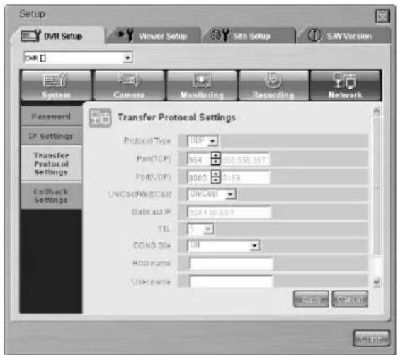
text_image
Setup DVR Setup Viewer Setup Site Setup SJW Version System Camera Monitoring Recording Network Password IP Settings Transfer Protocol Settings Callback Settings Transfer Protocol Settings Protocol Type: 016 Port(TCP): 564 308.558.587 Port(UDP): 9060 2159 UniCost/WallCost: UniCost Subcost IP: 224.136.631 TTL: 5 DDVD Site: CIB Host name: User name: © © © © © © © © © © © © © © © © © © © © © © © © © © © © © © © © © © © © © © © © © © © © © © © © © © © © © © © © © © © © © © © © © © © © © © © © © © © © © © © © © © © © © © © © © © © © © © © © © © © © ©©©©©©©©©©©©©©©©©©©©©©©©©©©©©©©©©©©©©©©©©©©©©©©©©©©©©©©©©©©©©©©©©©©©©©©©©©©©©©©©©©©©©©©©©©©©©©©©©©©©©°CIE® User name:- Callback
- You can set the Callback function of SHR-2040/2041/2042.
- In the event of Alarm, Motion Detection, or Video Loss, set the IP address and port of PC where SmartViewer is installed to forward Callback messages. In failure of message forwarding, set the value for retrial.
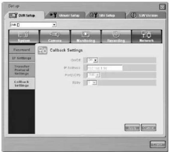
text_image
Setup DVR Setup Viewer Setup SRB Setup S.W. Version DVR System Camera Monitoring Recording Network Password IP Settings Transfer Protocol Settings Callback Settings Callback Settings OvOR: 08 IP Address: 192.168.1.16 Port(UDP): 500 Reply: 0Note
- SHR-2040/2041/2042 uses 4 ports for TCP connection.
- The PORT number is flexible and 4 consecutive numbers are grouped for the change (554,555,556,557 → 558,559,560,561)
- If you use the IP Router for network composition, you should allocate a protocol for SHR-2040/2041/2042.
Viewer Setup

Viewer Setup
- Click the [Viewer Setup] for Viewer Setup.
- Viewer Setup sets the various kinds of item related to the operation of Smart Viewer.
- Viewer setup is composed of Video Recording, File Converting, Sequence Time, OSD Display, Auto Connection, Callback Connection, and Language.
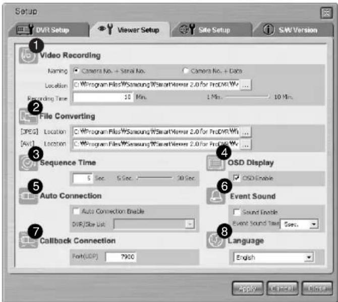
text_image
Setup DVR Setup Viewer Setup Site Setup SW Version 1 Video Recording Naming Camera No. + Serial No. Camera No. + Data Location C:\Program Files\Samsung\SmartViewer 2.0 for ProDVR.Wt ... Recording Time 10 Min. 1 Min. 10 Min. 2 File Converting [PEG] Location C:\Program Files\Samsung\SmartViewer 2.0 for ProDVR.Wt ... [AVI] Location C:\Program Files\Samsung\SmartViewer 2.0 for ProDVR.Wt ... 3 Sequence Time 5 Sec. 5 Sec. 30 Sec. OSD Display □ OSD Enable 5 Auto Connection □ Auto Connection Enable DVR/Site List 6 Event Sound □ Sound Enable Event Sound Time 5 sec. 7 Callback Connection Port(UDP) 7900 Language English 8 Apply Cancel Delete① Item to set the information necessary for saving the video data displayed into *.dvr file when connecting with SHR-2040/2041/2042.
② Item to set the information necessary for converting the file saved in your PC with *.dvr file into JPEG.
③ Item to set the information necessary for the auto sequence mode.
④ Item to set the information of Smart Viewer OSD.
⑤ Item to set whether Smart Viewer shall be automatically connected to DVR(SHR-2040/2041/2042) or Site when it begins running.
⑥ This is a menu item that is designed to set the alarming time when it receives an event message such as an alarm, motion and / or Video loss.
⑦ Item to set a port for the callback connection.
⑧ This item is for the language setup.
- Video Recording
① Naming
Camera No. + Serial No. Camera No. + Date
- Being connected to SHR-2040/2041/2042 in the monitoring or search mode, you can save the video displayed with *.dvr file and name it. - If you set to "Camera No. + Serial No.", the file name depends on the camera number and serial number. If set to "Camera No. + Date", it depends on the camera number, current date, and time.
② Location
C:\Program Files\WSamsung\W SHR 204204:2042 Sma ...
- When connecting with SHR-2040/2041/2042 in the monitoring or search mode and saving the video displayed, it sets the directory where *.dvr file to be saved. - The current default directory is "Directory that installs Smart Viewer Program \ video \ dvr".
③ Recording Time
1 Min. 1 Min. 10 Min.
- When connecting with SHR-2040/2041/2042 in the monitoring or search mode and saving the video displayed, it sets the maximum saving time. - The saving time can be set from 1 to 10 minutes. If the saving time exceeds the preset time, the saving stops automatically.
● File Converting [JPEG]
① Location
C:\Program Files\Samsung\SHR 2042041042 Sma
- You can convert the file saved in your PC with*.dvr format into JPEG file. The frames composing *.dvr file will be converted into JPEG file. Sets the directory in which the converted JPEG file will be saved. - The current default directory is "Directory that installs Smart Viewer Program \ frame".
- Sequence Time

- When connecting with SHR-2040/2041/2042 in the monitoring mode, set the auto sequence time if the auto sequence is set. The time can be set from 10 to 20 minutes.
- OSD Display

- Sets if OSD shall be displayed on each channel of Smart Viewer.
- Whether you check "Enable" or not, OSD will appear or not. However, Audio icon, PTZ icon, REC icon, and Alarm/Motion event icon will not be affected by the OSD condition.
- Callback Connection

- Sets the port for Callback connection.
● Auto Connection
- Sets if the smart viewer is automatically connected to SHR-2040/2041/2042 or site at the initial operation.
- If you check "Auto Connection Enable", the names of SHR-2040/2041/2042 and Site currently registered at the DVR/Site list will be displayed in the following list. If you select one from the list, the smart viewer will connect to the selected SHR-2040/2041/2042 or Site when it operates later.

text_image
Auto Connection Enable DVR/Site List -- DVR LIST ---- DVR [216] DVR [219] DVR [87] -- SITE LIST ---- Site [0] Site [1]- Language

- Sets the language used in the SmartViewer.
Site Setup

- Click the [Site Setup] button for Site Setup.
- The information of DVR(SHR-2040/2041/2042) or Site that you want to connect by Smart Viewer is set in the Site Setup.
- Smart Viewer allows you to connect with DVR(SHR-2040/2041/2042) or Site registered only here.
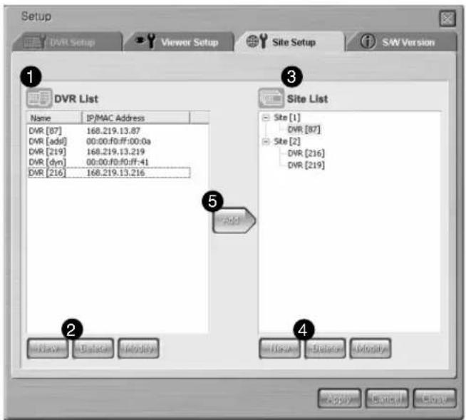
text_image
Setup DVR Setup Viewer Setup Site Setup S&W Version 1 DVR List Name IP/MAC Address DVR [87] 168.219.13.87 DVR [add] 00:00:f0:ff:00:0a DVR [219] 168.219.13.219 DVR [dyn] 00:00:f0:00:ff:41 DVR [216] 168.219.13.216 Site List Site [1] DVR [87] Site [2] DVR [216] DVR [219] Add Add Add Add Add Apply Remove Show① The DVR(SHR-2040/2041/2042) list that registered by the user is displayed.
② The button to add a new DVR(SHR-2040/2041/2042), delete, or edit the exist DVR(SHR-2040/2041/2042)
③ The site list that registered by the user is displayed.
④ The button to add a new site, delete, edit the exist site, or delete DVR(SHR-2040/2041/2042) that composes the site.
⑤ The button to add DVR(SHR-2040/2041/2042) selected from the DVR list to the Site selected from the Site list.
- DVR List

text_image
DVR List Name IP/MAC Address DVR [87] 168.219.13.87 DVR [adsI] 00:00:f0:ff:00:0a DVR [219] 168.219.13.219 DVR [dyn] 00:00:f0:f0:ff:41 DVR [216] 168.219.13.216 New Delete.Modify- The information of DVR(SHR-2040/2041/2042) that you want to connect by Smart Viewer is set in the DVR List.
- You can register a new DVR(SHR-2040/2041/2042) or delete and edit the DVR(SHR-2040/2041/2042) selected from the registered list, and the name and IP / MAC Address of the registered DVR(SHR-2040/2041/2042) is displayed in DVR List.
- If your DVR (SHR-2040/2041/2042) uses a static IP, select "Static IP" for Address Type and type in the name of the DVR (SHR-2040/2041/2042) and the IP address.
- Select "Port" so that it matches the port number that you've set in the network menu of DVR (SHR-2040/2041/2042).

text_image
New DVR DVR Information Address Type Static IP Name DVR IP Address 0 0 0 0 MAC Address 00 02 00 00 00 00 Port No. 554,555,556,557 Login Information Admin User Password OK Cancel- If your DVR (SHR-2040/2041/2042) uses a dynamic IP such as in a cable modem or VDSL, or PPPoE for ADSL, select "MAC Address" for Address Type and type in the MAC address of the DVR (SHR-2040/2041/2042).
- Select "Port" so that it matches the port number that you've set in the network menu of DVR (SHR-2040/2041/2042).

text_image
New DVR DVR Information Address Type: MAC Address Name: DVR IP Address: 0 0 0 0 0 MAC Address: 00 00 00 00 00 00 Port No: 554,555,556,557 Login Information ○ Admin ○ User Password OK Cancel- If you select "Use DDNS" in the network settings menu of DVR (SHR-2040/2041/2042) or use an IP splitter to register an URL using DDNS, you can make connection via the URL.
- If you want to make connection via the an URL, select "URL" for Address Type and type in the URL set for the DVR or IP splitter in the URL menu item.
- Select "Port" so that it matches the port number that you've set in the network menu of DVR (SHR-2040/2041/2042).

text_image
New DVR DVR Information Address Type: URL Name: DVR URL MAC Address: 00 00 00 00 00 00 Port No.: $54,555,556,557 Login Information ○ Admin ○ User Password OK CancelNote
- The MAC address of DVR is written at the side label of the product.
It is also found in the system information of DVR Menu. - If the DVR(SHR-2040/2041/2042) is connected to ADSL, the network bandwidth is low. Therefore, the transfer rate becomes low and the viewer operates in the more limited range.
- The viewer can monitor up to 4CH all the same time.
- The viewer can search or play only 1CH.
- The audio does not play.
- The number of playback frame is 0.5 ips in average, but it is variable depending on the number of channel and video size under simultaneous monitoring.
② Deletion of an old DVR(SHR-2040/2041/2042)

- If you select a DVR(SHR-2040/2041/2042) in the DVR list for deletion and press the [Delete] button, the following message box pops up. Press the [OK] button to delete the DVR(SHR-2040/2041/2042).
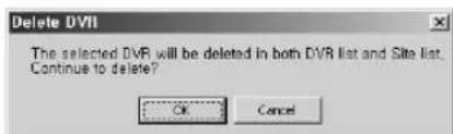
text_image
Delete DVD The selected DVR will be deleted in both DVR list and Site list. Continue to delete? OK Cancel- When the DVR(SHR-2040/2041/2042) for deletion is connected with the Smart Viewer, the following message box pops up and the DVR(SHR-2040/2041/2042) cannot be deleted. Be sure to cut the connection between the DVR(SHR-2040/2041/2042) and the Smart Viewer before you delete it.

text_image
Delete DVR The Site/DVR to be deleted is now connected! Disconnect before deleting. OK③ To Edit the old DVR(SHR-2040/2041/2042)

- If you select a DVR(SHR-2040/2041/2042) in the DVR list to edit and press the [Edit] button, the following message box pops up. Press [OK] button to edit the DVR(SHR-2040/2041/2042).
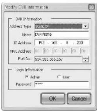
text_image
Modify DVR Information DVR Information Address Type: Static, IP Name: DVR Name IP Address: 192 . 168 . 0 . 200 MAC Address: 00 00 00 00 00 00 Port No.: 554,555,556,557 Login Information ○ Admin ○ User- Password: ****** OK Cancel- When the DVR(SHR-2040/2041/2042) to edit is connected with the Smart Viewer, the following message box pops up and the DVR(SHR-2040/2041/2042) cannot be edited. Be sure to cut the connection between the DVR(SHR-2040/2041/2042) and the Smart Viewer before you edit it.

text_image
Modify DVR The Site/DVR to be modified is now connected! Disconnect before modifying. OK- Site List
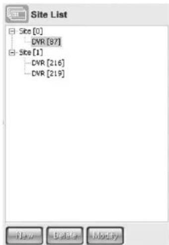
text_image
Site List Site [0] CVR [87] Site [1] CVR [216] CVR [219]- You can register and control the many DVRS(SHR-2040/2041/2042) to be connected with the smart viewer at once with a site in the site list. You are allowed to register a new site, and delete or edit the selected site in the registered list. Also, you can add or delete a DVRS(SHR-2040/2041/2042) to the site selected in the site list.
- In the site list, both the name of a registered site and the name of DVRS(SHR-2040/2041/2042) that composes the site are displayed with a list. You can also set up up to 16 DVRS(SHR-2040/2041/2042) for one site.
① New site addition

- If you press the [New] button, the following window pops up and you can allowed to input the information for a new site.
- The information to be input is the site name.
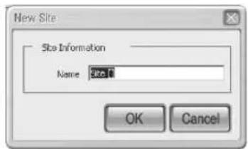
text_image
New Site Site Information Name: site1 OK Cancel② To delete an old site or DVR(SHR-2040/2041/2042)

- If you select a site or DVR(SHR-2040/2041/2042) in the site list for deletion and press the [Delete] button, the following message box pops up. Press the [OK] button to delete either site or DVR(SHR-2040/2041/2042).
- When deleting the DVR(SHR-2040/2041/2042), it is deleted from the site composition but the DVR(SHR-2040/2041/2042) information is not deleted.
text_image
Delete Site The selected Site/DVR will be deleted in Site list. Continue to delete?- When the site to delete or the site that is composed of the DVR (SHR-2040/2041/2042) to delete is connected with the Smart Viewer, the following message box pops up and the site or the DVR (SHR-2040/2041/2042) cannot be deleted. Be sure to cut the connection between the DVR (SHR-2040/2041/2042) and the Smart Viewer before you delete it.

text_image
Delete Site The Site/DVR to be deleted is now connected! Disconnect before deleting. OK③ To edit the information of an old site

- If you select a site in the site list to edit and press the [Edit] button, the following message box pops up and you can edit the site information.
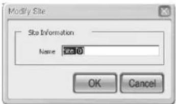
text_image
Modify Site Site Information Name: site 0 OK Cancel- When the site to edit is connected with the Smart Viewer, the following message box pops up and the site cannot be edited. Be sure to cut the connection between the DVR(SHR-2040/2041/2042) and the Smart Viewer before you edit it.

text_image
Modify Site The Site/DVR to be modified is now connected! Disconnect before modifying. OK- If you select a DVR(SHR-2040/2041/2042) and press the [Edit] button, the following message box pops up and the DVR(SHR-2040/2041/2042) cannot be edited. To edit the DVR(SHR-2040/2041/2042), go to the DVR list.
text_image
Modify Site The modification of DVR information can be done in DVR list! OK● To add a DVR(SHR-2040/2041/2042) to the site

- If you press the [Add] button, the DVR(SHR-2040/2041/2042) selected in the DVR list is added to the site selected in the site list.
- You can add up to 14 DVRs (SHR-2040/2041/2042) to one site, and you also can delete the DVRs that compose the site from the site list.
- If you press the [Add] button unless a site is registered in the site list, a new site named "Site [0]" as a default is created and the DVR(SHR-2040/2041/2042) add to it.
- When the site to add a DVR (SHR-2040/2041/2042) is connected with the Smart Viewer, the following message box pops up and the addition of DVR(SHR-2040/2041/2042) to the site is impossible. Be sure to cut the connection between the DVR(SHR-2040/2041/2042) and the Smart Viewer before you add a DVR(SHR-2040/2041/2042).

text_image
Add to Site The Site for the selected DVR to be added to is now connected! Disconnect before adding. OKS/W Version

S/W Version
- If you press the [S/W Version] button, the smart viewer version, system requirements, and the version of DVR(SHR-2040/2041/2042) System S/W, being connected to the smart viewer, are displayed.
- You can upgrade the on-line DVR(SHR-2040/2041/2042) System S/W remotely. You are authorized with S/W upgrade in an Admin authority only. With the authority of user or without connecting with the DVR(SHR-2040/2041/2042), your access will be denied.
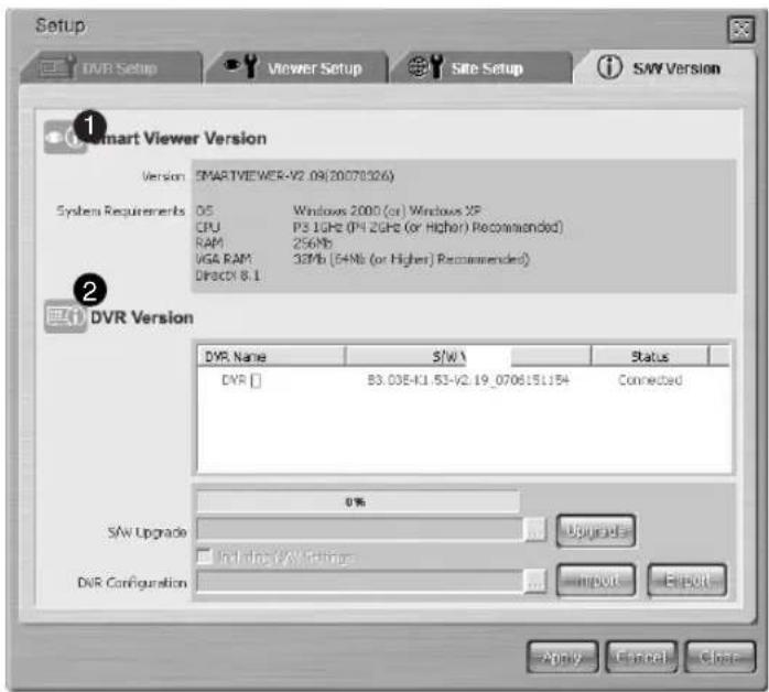
text_image
Setup DVR Setup Viewer Setup Site Setup SAY Version Smart Viewer Version Version: SMARTVIEWER-V2.09(20070326) System Requirements OS Windows 2000 (or) Windows XP CPU PS1GHz (PH 2GHz (or Higher) Recommended) RAM 256Mb VGA RAM 32Mb (64Mb (or Higher) Recommended) DIRECTX 8.1 DVR Version DVR Name S/W Status DVR [] B3.03E-K1.53-V2.19_0706151154 Connected SAV Upgrade Include SAW Upgrade DVR Configuration 0% Upgrade Import Export Apply Cancel Close① Displays the smart viewer version and system requirements.
② Displays the version and name of DVR if any DRV(SHR-2160/2162/2080/2082) is being connected with the Smart Viewer. This area can also provide functions for remotely upgrading the DVR software, extracting, and recovering the DVR settings.
● Smart Viewer Version
| Version | SMARTVIEWER-V2.09(20070326) | |
| System Requirements | OS | Windows 2000 (or) Windows XP |
| CPU | P3 1GHz (P4 2GHz (or Higher) Recommended) | |
| RAM | 256Mb | |
| VGA RAM | 32Mb (64Mb (or Higher) Recommended) | |
| DirectX 8.1 | ||
- Smart Viewer Version and system requirements are displayed.
- DVR Version
| DYR Name | S/W Version | Status |
| DVR [216] DVR [219] | :SHR-20402041/2042 -MAIN-V0.5-200501251626 Unknown | Connected Not Connected |
- DVR Version not only displays the connected DVR(SHR-2040/2041/2042) name if any DVR(SHR-2040/2041/2042) is being connected with Smart Viewer or the name of DVR(SHR-2040/2041/2042) composing a site if any DVR(SHR-2040/2041/2042) is being connected with the site but also displays DVR(SHR-2040/2041/2042) S/W version.
- When the smart viewer does not connected with the DVR(SHR-2040/2041/2042), it displayed with a gray and "Not connected" is displayed in the status.
- Each DVR Version has a check box, which is used for S/W Upgrade.
● DVR(SHR-2040/2041/2042) S/W Upgrade
- Smart Viewer upgrades on-line DVR(SHR-2040/2041/2042) S/W remotely.
① Select a DVR(SHR-2040/2041/2042) to be upgraded among DVRs(SHR-2040/2041/2042) on line.
| DVR Name | S/W Version | Status | |
| ✓ DVR [216] | SHR-20402041/2042 -MAIN-V0.5-200501261626 | Connected | |
| DVR [219] | Unknown | Not Connected |
② Click the following button to open the "SHR-2040/2041/2042 Firmware" file in format.

text_image
Open Look in: SHR- 2040/2041/2042 SmartViewer video File name: -.tgz Files of type: SHR- 2040/2041/2042 Firmware Files (*.tgz) Open Cancel③ Press the [Upgrade] button to transmit a file to the selected DVR(SHR-2040/2041/2042) and start the upgrade of DVR (SHR-2040/2041/2042) S/W.

④ The progress of file transmission and upgrade is displayed at the bottom.

Caution
Be sure to suspend all the DVR system functions in action such as recording, MENU, backup, and playback before you upgrade the DVR(SHR-2040/2041/2042) S/W. Never try to turn the DVR(SHR-2040/2041/2042) power off during the S/W upgrade.
The S/W upgrade requires about 5 minutes. If the S/W upgrade is suspended accidentally, the previous S/W will be left intact.
Note
The new Firmware necessary for DVR(SHR-2040/2041/2042) S/W upgrade should be downloaded from the CCTV Part in Products Section at the http://www.samsung.com
● Extracting the settings for DVR(SHR-2160/2160/2080/2082)
- S martViewer enables you to extract the menu settings for the connected DVR(SHR-2160/2160/2080/2082).
① Select the DVR you want to extract the setting values from.
| DVR Name | S/W Version | Status |
| ✓LOCAL_21 | B3.03E-K1.30-V2.17_0701041514 | Connected |
| DVR [219] | Unknown | Not Connected |
② Press the [Export] button to specify the file name (*.dat), then the setting values can be saved on your PC.

● Recovering the menu setting values for DVR(SHR-2160/2160/2080/2082)
- SmartViewer enables you to restore the menu settings for the connected DVR(SHR-2160/2160/2080/2082).
① Select the DVR you want to restore the setting values.
| DVR Name | S/W Version | Status |
| ✓LOCAL_21 | B3.03E-K1.30-V2.17_0701041514 | Connected |
| DVR [219] | Unknown | Not Connected |
② Click the button as shown below to open a menu setup file (*.dat).

natural_image
Simple horizontal bar with a circular button containing three dots, no text or symbols present.③ Press the [Import] button to transfer the setup file to the selected DVR. Then the menu settings are recovered.

④ When you restore the settings, click the following checkbox to recover the network settings if necessary.

Note
Import/Export function does not affect for the Motion Detection Setup Area and Record Schedule.
natural_image
Abstract digital illustration of circuit board and server racks (no text or symbols)Appendix
1
Product Specification
| Item Details Remarks | |||||
| OS Embedded OS | |||||
| Broadcasting NTSC/PAL System | |||||
| Input Voltage 2040-DC 12V, AC 110-220(NTSC),AC 100-230(PAL)2041/2042 - AC 110-220(NTSC)AC 100-230(PAL) | |||||
| Power Consumption | 2040:30Watt, 2041:60Watt, 2042:51Watt | ||||
| Video Composite 2 Channel | Composite 4 Channel-1.0Vp-p-75Ω Hi Z TerminationBNC TypeLoop Through Out 4 Channel-Auto Termination | ||||
| Audio Mono 1 Channel | Mono 4 ChannelAudio Input - -5dBm, 600 ΩRCA Type | ||||
| Live Single Monitoring 4 Split | PIPMode sequenceFreeze2 X Zoom | ||||
| Recording | Compression Video: MPEG4Method Audio: ADPCM | ||||
| Video Size & Very Performance | Resolution | Quality Level Max Image Rate | |||
| CIF(C) High352X240(NTSC)/352X288(PAL) | Very HighStandardLow | 30.00ips(NTSC)/25.00ips(PAL) | |||
| Half D1(N)720X288(NTSC)/720X288(PAL) | HighStandardLow | 15.00ips(NTSC)/12.50ips(PAL) | |||
| Full D1(L)720X480(NTSC)/720X576(PAL) | Very HighHighStandardLow | 30.00ips(NTSC)/25.00ips(PAL) | |||
| Recording Mode | Normal → REC KeySchedule → Schedule TableEvent-Alarm Detection-Motion Detection-Video Loss-Pre & Post Recording | ||||
| Time Laps | NTSC: 1.00ips/3.00ips/5.00ips/7.50ips/10.00ips/15.00ipsPAL: 1.00ips/2.50ips/5.00ips/6.25ips/8.33ips/12.50ips/25.00ips | ||||
| Storage Capacity | Internal SHR-2042: ATA | SHR-2040: ATA HDD x 2(MAX)-MAX HDD Size: 500GB x 2 = 1TBSHR-2041: ATA HDD x 4(MAX)-MAX HDD Size: 500GB x 4 = 2TB HDD x 3(MAX)-MAX HDD Size: 500GB x 3 = 1.5TB | |||
| External | USB HDD-MAX 1 (Not support USB hub)-MAX HDD Size: 500GB | ||||
| Item Details | Remarks | ||||
| Play Back | Search Mode | Calendar Event- Normal, Schedule, Alarm, Motion, Video Loss Date/TimeGo to FirstGo to LastBackup Data | |||
| Video size & Performance | Video size | Decoding Performance | |||
| 1Ch Mode | 4Ch Mode | ||||
| CIF | 30.00ips(NTSC)/25.00ips(PAL) | 30.00ips(NTSC)/25.00ips(PAL)/1CH | |||
| Half D1(N) | 30.00ips(NTSC)/25.00ips(PAL) | 15.00ips(NTSC)/12.50ips(PAL)/1CH | |||
| Full D1(L) | 30.00ips(NTSC)/25.00ips(PAL) | Not supported by SHR-2040/2041/2042 | |||
| Full D1 is supported in the 1 ch mode only | |||||
| Display Mode | Single → 1Channel Decoding4 Split → 4Channel DecodingPIP → 1Channel Decoding + 1Channel Live6 Split → PB(Single)+4 Channel Live- Single→ 6 Split(1CH PB)→PIP→4 Split9 Split → PB(4 Split)+4 Channel Live- 4 Split→ 6 Split(4CH PB)→4 Split | ||||
| Play Mode Fast Forward/Fast Reverse- 2x, 4x, 8x, 16x, 32x, 64x | |||||
| Backup | USB External HDDUSB CD/DVD WriterUSB Flash Memory | ||||
| Alarm | Input: 4 Input- 5mAOutput: 2 Relay Output- 2A/30VDC, 0.5A/125VACReset: 1 Input- 5mA | ||||
| Network | Ethernet: 10/100 Base T, ADSL(PPPoE), DHCP | ||||
| Serial I/F | RS-485 → PTZ Device Control, Remote Control Device | ||||
| Remote Viewer | PC Spec. | CPU: Pentium III, 1GHz or higherRAM: SDRAM 256MB or higherGraphic Accelerator: Graphic Memory32MB or higherDirectX: 8.1 or higher | |||
| Support OS | Win2000, WinXP | ||||
| Function | Live Image Monitoring ModeLocal File Search & Play Back ModeRemote File Search & Play Back Mode | ||||
| Operation Temp. 0 | °C to 40°C (32°F to 104°F) | ||||
| Preservation Temp. | -20°C to 60°C (-4°F to 140°F) | ||||
| Operation Humidity 20% ~ 85% RH | |||||
| Preservation Humidity 20% ~ 85% RH | |||||
| Size | 215(W) X 88(H) X 337(D) (2040)430(W) X 88(H) X 400(D) (2041/2042) | ||||
| Weight | About 3.35Kg(2040)/About 6.5Kg(2041)/About 7.3Kg(2042) | ||||
2
Outline Drawings

text_image
SAMSUNG[SHR-2040]
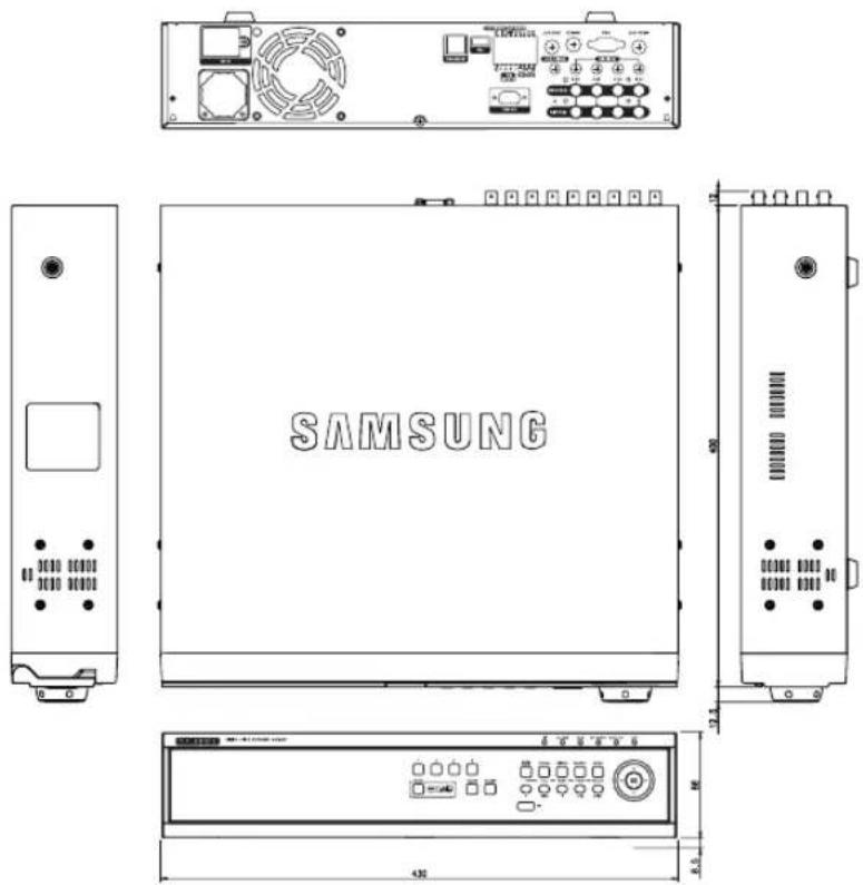
text_image
SAMSUNG[SHR-2041]

text_image
SAMSUNG[SHR-2042]
3F
Factory Default
This restores the Network information and preset values in SHR-2040/2041/2042 to the original state at the time of factory shipment.
Factory Default will be done as follows;
- Use System / Load Factory Default in MENU or,
- If you hold on to the Mode button in Live Mode and keep pressing the CH2 button for 5 seconds, the system will return to the Factory default condition. The front button repeats the flickering.
| Classification | Detailed Items Factory Setup | ||
| System Setup | Time/Date/Language | Date Format YYYY-Y-MM-DD | |
| Time Format 24 Hours | |||
| Language English | |||
| Summer Time Off | |||
| Password | Password 4321 | ||
| Password Lock On | |||
| HDD Mode | Disk End Mode Overwrite | ||
| Disk End Beep Off | |||
| Camera Setup | Camera Config | Video On | |
| Audio Off | |||
| Title CAM_01 ~ CAM_4 | |||
| Auto Seq. 5 sec | |||
| PTZ Device | ID | Camera No. | |
| Protocol | None | ||
| Baudrate | 9600 | ||
| Parity | None | ||
| Data | 8 | ||
| Stop | 1 | ||
| Serial Mode | Half Duplex | ||
| Screen Setup | Brightness | 50 | |
| Contrast | 50 | ||
| Color 50 | |||
| Classification Detailed Items Factory Setup | |||
| Monitoring Title | Event Monitoring D OSD Display Time On | Duration Off | |
| ate On | |||
| e On | |||
| Status On | |||
| Spot Out Channel CH1 | |||
| Spot Out Event Monitor Off | |||
| Monitor Out Composite Out | |||
| 1CH DVR Support Off | |||
| Record Mode Video Setup | Mode On | ||
| Mode Size CIF | |||
| Quality | Standard | ||
| Rate | 30ips(NTSC)/25ips(PAL) | ||
| Record Schedule | Continuous Recording | Off | |
| Event Recording | On | ||
| Event Record Setup | Event Record Mode | Video Size | CIF |
| Video Size | Normal | ||
| Rate | 30ips(NTSC)/25ips(PAL) | ||
| PreEvent | Off | ||
| PostEvent | Off | ||
| Alarm Detection Setup | Sensor State | Off | |
| Camera | Camera No. | ||
| Alarm-Out | None | ||
| Duration | 10 sec | ||
| Motion Detection Setup | M.D State | Off | |
| Area | All Area | ||
| Sensitivity | High | ||
| Alarm-Out | None | ||
| Duration | 10 sec | ||
| Video Loss Detection Setup | Video Loss Detection Setup | Off | |
| Alarm-Out | None | ||
| Duration | 10 sec | ||
| Network | IP Settings | Connection Mode Static IP | |
| Bandwidth 2Mbps | |||
| Admin Password 4321 | |||
| User Password 4321 | |||
| IP 192.168.001.200 | |||
| Gateway | 192.168.001.001 | ||
| Subnet Mask 255.255.255.000 | |||
| DNS | 168.126.063.001 | ||
| ADSL User ID ID | |||
| Password - | |||
| Transfer Protocol Settings | Protocol type UDP | ||
| Port(TCP) | 554.555.556.557 | ||
| Port(UDP) | 8000-8159 | ||
| Unicast / Multicast Unicast | |||
| Multicast IP 224.126.063.001 | |||
| TTL 005 | |||
| DDNS Site Off | |||
| Host Name | - | ||
| User Name | - | ||
| User Password | - | ||
| Callback Settings | On / Off | Off | |
| IP Address | 192.168.001.010 | ||
| Port(UDP) | 7900 | ||
| Retry | 05 | ||
SHR-2040/2041/2042 Smart Viewer Frame Specification for the Playback
NTSC
| FRAME Viewer Screen RATE Split Mode | VIDEO SIZE | ||
| 15 | Half D1(N) CIF (C) | ||
| Nine-split 1 frame/sec 15 frame/sec | |||
| Fore-split 15 frame/sec 15 frame/sec | |||
| Single 15 frame/sec 15 frame/sec | |||
| 10 | Half D1(N) CIF (C) | ||
| Nine-split 10 frame/sec 10 frame/sec | |||
| Fore-split 10 frame/sec 10 frame/sec | |||
| Single 10 frame/sec 10 frame/sec | |||
| 7.5 | Half D1(N) CIF (C) | ||
| Nine-split 7.5 frame/sec 7.5 frame/sec | |||
| Fore-split 7.5 frame/sec 7.5 frame/sec | |||
| Single 7.5 frame/sec 7.5 frame/sec | |||
| 5 | Half D1(N) CIF (C) | ||
| Nine-split 5 frame/sec 5 frame/sec | |||
| Fore-split 5 frame/sec 5 frame/sec | |||
| Single 5 frame/sec 5 frame/sec | |||
| 3 | Half D1(N) CIF (C) | ||
| Nine-split 3 frame/sec 3 frame/sec | |||
| Fore-split 3 frame/sec 3 frame/sec | |||
| Single 3 frame/sec 3 frame/sec | |||
| 1 | Half D1(N) CIF (C) | ||
| Nine-split 1 frame/sec 1 frame/sec | |||
| Fore-split 1 frame/sec 1 frame/sec | |||
| Single 1 frame/sec 1 frame/sec | |||
PAL
| FRAME Viewer Screen RATE Split Mode | VIDEO SIZE | ||
| 12.5 | Half D1(N) CIF (C) | ||
| Nine-split 1 frame/sec 12.5 frame/sec | |||
| Fore-split 12.5 frame/sec 12.5 frame/sec | |||
| Single 12.5 frame/sec 12.5 frame/sec | |||
| 8.33 | Half D1(N) CIF (C) | ||
| Nine-split 8.33 frame/sec 8.33 frame/sec | |||
| Fore-split 8.33 frame/sec 8.33 frame/sec | |||
| Single 8.33 frame/sec 8.33 frame/sec | |||
| 6.25 | Half D1(N) CIF (C) | ||
| Nine-split 6.25 frame/sec 6.25 frame/sec | |||
| Fore-split 6.25 frame/sec 6.25 frame/sec | |||
| Single 6.25 frame/sec 6.25 frame/sec | |||
| 5 | Half D1(N) CIF (C) | ||
| Nine-split 5 frame/sec 5 frame/sec | |||
| Fore-split 5 frame/sec 5 frame/sec | |||
| Single 5 frame/sec 5 frame/sec | |||
| 2.5 | Half D1(N) CIF (C) | ||
| Nine-split 2.5 frame/sec 2.5 frame/sec | |||
| Fore-split 2.5 frame/sec 2.5 frame/sec | |||
| Single 2.5 frame/sec 2.5 frame/sec | |||
| 1 | Half D1(N) CIF (C) | ||
| Nine-split 1 frame/sec 1 frame/sec | |||
| Fore-split 1 frame/sec 1 frame/sec | |||
| Single 1 frame/sec 1 frame/sec | |||
Note
The play frame specification of Smart Viewer varies on the setup of SHR-2040/2041/2042 Recording Rate and Video Size or the screen split mode of Smart Viewer. The above specification is applicable only when the main body of SHR-2040/2041/2042 is connected with a fast network like LAN. When the main body of SHR-2040/2041/2042 is connected with a slow network like ADSL, the play speed will be 0.5 Frame/sec. In addition, the above specification has been defined to the recommended specification of your PC. If your PC specification is lower than the recommended, the number of frame to played may diminish.
Troubleshooting(FAQ)
-
The system power is dead and LED in front of the system does not operate at all.
-
Please check the power connection.
- Check the power voltage.
-
If all your efforts like above end up with nothing, check or exchange the power supply.
-
Video data remains in the system but some channels displays no video data but turns all blue.
-
Check the image of the camera connected to the system. Improper input of camera input may cause this symptom.
- Check the camera power supply.
-
Sometimes, you see this symptom when the video data is connected with multisystems and the video signal from the video data distributor in use feels weak. If it's the case, you shall connect the camera images with SHR-2040/2041/2042 DVR directly to check or improve such a symptom.
-
The REC button in front has no effect on turning on REC LED or recording process.
-
Please check the HDD space.
-
Please check the Record Mode setup in MENU. It should be On.
-
All the front LEDs are in operation but the monitor remains black.
- Video out may come out differently with the connected monitor. In short, Video Out is set to Composite Output but connected to VGA Input Monitor or vice versa. Then, keep pressing both the "MODE" button and the "1" button on the left for 5 seconds to change the Video Out mode.
- The front LED blinks and the logo screen repeatedly appears.
- This symptom may be resulted from failure of HDD connection inside SHR-2040/2041/2042 DVR. Take off the cover and check HDD connection status. If HDD connection has no problem, please consult with the shop where you bought SHR-2040/2041/2042 DVR.
- You cannot enter MENU by forgotten password.
- If you forget the password, you shall reset SHR-2040/2041/2042 DVR to the values set at the factory. Keep pressing both the "MODE" button and the "2" button on the left for 5 seconds The password default is "4321".
- The channel button does not operate in Live.
- If the current screen is Event Monitoring, the channel button does not operate. Then, press the Alarm button to terminate the current screen and select a channel.
- The cursor cannot reach Start during Calendar Search.
- Please check both the channel and the date for play are left checked. Both shall be checked for play with Start. The cursor cannot reach the unrecorded date.
- Alarm, once issued, keeps being issued though you press the front Alarm button for cancellation.
- Press the front Menu button to cancel Alarm as follows.
1) To cancel Event Monitoring Screen : Monitoring-Event Monitoring Duration Off
2) To cancel Buzzer : Event Record-Alarm (Motion Detection/Video Loss). Alarm-Out.
3) To cancel Event : Event Record-Alarm (Motion Detection/Video Loss). State Off.
- Pressing the PTZ button in Live receives no response.
- Check the Protocol and other setup values through Menu → Camera → PTZ Device match with the PTZ camera.
- When you connect several IEEE1394 armored HDDs to SHR-2040/2041/2042
DVR through Menu, SHR-2040/2041/2042 DVR cannot recognize all the HDDs.
- It requires time to recognize several armored HDDs. Please try again in a few minutes. If retrial makes no improvement, HDD could be abnormal. Please exchange the HDD.
- "CLOCK BATTERY HAS FAILED" is displayed on the screen.
This message is displayed if the internal clock in DVR has problem.
DVR will not work in order to protect recorded data in HDDs.
Please consult with an expert who works for the shop where you bought the product.
- You cannot connect to SHR-2040/2041/2042 DVR through Smart View.
- Check if 3 Smart Viewer users are in connection with SHR-2040/2041/2042 DVR. SHR-2040/2041/2042 DVR allows no more than 3 users' connection with Smart Viewer at a time.
- Check the Network setup of SHR-2040/2041/2042 DVR.
- Check Network cable connection.
- When you use DHCP/ADSL(PPPoE) for connection, please check if you get the right SHR-2040/2041/2042 DVR MAC Address.
- If SHR-2040/2041/2042 DVR is connected to the ADSL network, please check if Bandwidth is set below 600 Kbps. If the Bandwidth for ADSL is set to high, the connection with Smart Viewer may be instable due to the heavy network load as the ADSL speed is low.
-
Smart Viewer in operation is disconnected.
-
If you change time, network setup, HDD format, Default Setup, or HDD attachment or detachment for SHR-2040/2041/2042 DVR, the current Smart Viewer will be automatically disconnected.
- Check network connection. Smart Viewer, if disconnected from Network, will try reconnection up to 5 times. If it remains unconnected after 5 time trial, it will automatically give up connection.
-
As far as SHR-2040/2041/2042 DVR is connected to the ADSL network, you may be disconnected from Smart Viewer when the network conditions goes bad.
-
The Audio icon of Smart Viewer is left inactivated in the Live mode. Setting Audio to On in the Camera menu of SHR-2040/2041/2042 DVR will make no difference.
- If your PC has no Audio driver or has some problem with Audio play of an Audio driver, the Audio icon will be inactivated. Please check Audio driver installation status.
- When selecting the channel which PTZ Camera is connected to in the Live mode of Smart Viewer, click the "Menu Control" button among PTZ setup buttons to enter the Function Menu mode in PTZ Camera, and return from the other channel, the PTZ related buttons have been initialized.
- PTZ control is available in both Smart Viewer and SHR-2040/2041/2042 DVR. Other user might control PTZ for SHR-2040/2041/2042 DVR to terminate the PTZ Camera Menu or Auto Pan/Scan/Pattern motions while you select the other channel. This may cause the initialization.
- No Time Bar in the Search
- Time Line can be converted into 2 modes, General(24 Hour Display) and Extension(2 Hour Display). In the Extension mode, Time Bar may not be seen in the current time. Please enter the General mode or click the LEFT or RIGHT button to search Time Bar.
- "NO HDD" icon and error message pops up.
- Please check the HDD connection status. If this problem persist without connection failure, contact the technical support for checking hard disk.
- DVR device does not show what has been upgraded after adding a hard disk.
- Make sure that the additional external HDD installed is one of the devices listed on the compatibility list of HDDs. The list of the compatible devices with Samsung DVR can be obtained from your vendor.
- The connection status is not shown after connecting the external storage device, USB memory, USB HDD and such.
- Make sure that the external storage device installed is one of the storage devices listed on the compatibility list of storage devices. The list of the compatible devices with Samsung DVR can be obtained from your vendor.
Open source license report on the product
This product uses software provided under the name of GPL and LGPL.
You can receive the following GPL and LGPL source codes by email request to www.sec.co.kr.
- GPL Software
Kernel, Busybox, Sysvinit, dvd+rw-tools, cdrtools, dosfstools
- LGPL Software
gLibc, Inetutils
GNU GENERAL PUBLIC LICENSE
Version 2, June 1991
Copyright (C) 1989, 1991 Free
Software Foundation, Inc.
51 Franklin Street, Fifth Floor, Boston,
MA 02110-1301, USA
Everyone is permitted to copy and distribute verbatim copies of this license document, but changing it is not allowed.
Preamble
The licenses for most software are designed to take away your freedom to share and change it. By contrast, the GNU General Public License is intended to guarantee your freedom to share and change free software--to make sure the software is free for all its users. This General Public License applies to most of the Free Software Foundation's software and to any other program whose authors commit to using it. (Some other Free Software Foundation software is covered by the GNU Lesser General Public License instead.) You can apply it to your programs, too.
When we speak of free software, we are referring to freedom, not price. Our General Public Licenses are designed to make sure that you have the freedom to distribute copies of free software (and charge for this service if you wish), that you receive source code or can get it if you want it, that you can change the software or use pieces of it in new free programs; and that you know you can do these things.
To protect your rights, we need to make restrictions that forbid anyone to deny you these rights or to ask you to surrender the rights. These restrictions translate to certain responsibilities for you if you distribute copies of the software, or if you modify it.
For example, if you distribute copies of such a program, whether gratis or for a fee, you must give the recipients all the rights that you have. You must make sure that they, too, receive or can get the source code. And you must show them these terms so they know their rights.
We protect your rights with two steps: (1) copyright the software, and (2) offer you this license which gives you legal permission to copy, distribute and/or modify the software.
Also, for each author's protection and ours, we want to make certain that everyone understands that there is no warranty for this free software. If the software is modified by someone else and passed on, we want its recipients to know that what they have is not the original, so that any problems introduced by others will not reflect on the original authors' reputations.
Finally, any free program is threatened constantly by software patents. We wish to avoid the danger that redistributors of a free program will individually obtain patent licenses, in effect making the program proprietary. To prevent this, we have made it clear that any patent must be licensed for everyone's free use or not licensed at all.
The precise terms and conditions for copying, distribution and modification follow.
TERMS AND CONDITIONS FOR COPYING, DISTRIBUTION AND MODIFICATION
- This License applies to any program or other work which contains a notice placed by the copyright holder saying it may be distributed under the terms of this General Public License. The
"Program", below, refers to any such program or work, and a "work based on the Program" means either the
Program or any derivative work under copyright law: that is to say, a work
containing the Program or a portion of it, either verbatim or with modifications and/or translated into another language. (Hereinafter, translation is included without limitation in the term "modification".) Each licensee is addressed as "you".
Activities other than copying, distribution and modification are not covered by this License; they are outside its scope. The act of running the Program is not restricted, and the output from the Program is covered only if its contents constitute a work based on the Program (independent of having been made by running the Program). Whether that is true depends on what the Program does.
- You may copy and distribute verbatim copies of the Program's source code as you receive it, in any medium, provided that you conspicuously and appropriately publish on each copy an appropriate copyright notice and disclaimer of warranty; keep intact all the notices that refer to this License and to the absence of any warranty; and give any other recipients of the Program a copy of this License along with the Program.
You may charge a fee for the physical act of transferring a copy, and you may at your option offer warranty protection in exchange for a fee.
- You may modify your copy or copies of the Program or any portion of it, thus forming a work based on the Program, and copy and distribute such modifications or work under the terms of Section 1 above, provided that you also meet all of these conditions:
a) You must cause the modified files to carry prominent notices stating that you changed the files and the date of any change.
b) You must cause any work that you distribute or publish, that in whole or in part contains or is derived from the Program or any part thereof, to be licensed as a whole at no charge to all third parties under the terms of this License.
c) If the modified program normally reads commands interactively when
run, you must cause it, when started running for such interactive use in the most ordinary way, to print or display an announcement including an appropriate copyright notice and a notice that there is no warranty (or else, saying that you provide a warranty) and that users may redistribute the program under these conditions, and telling the user how to view a copy of this License. (Exception: if the Program itself is interactive but does not normally print such an announcement, your work based on the Program is not required to print an announcement.)
These requirements apply to the modified work as a whole. If identifiable sections of that work are not derived from the Program, and can be reasonably considered independent and separate works in themselves, then this License, and its terms, do not apply to those sections when you distribute them as separate works. But when you distribute the same sections as part of a whole which is a work based on the Program, the distribution of the whole must be on the terms of this License, whose permissions for other licensees extend to the entire whole, and thus to each and every part regardless of who wrote it.
Thus, it is not the intent of this section to claim rights or contest your rights to work written entirely by you; rather, the intent is to exercise the right to control the distribution of derivative or collective works based on the Program.
In addition, mere aggregation of another work not based on the Program with the Program (or with a work based on the Program) on a volume of a storage or distribution medium does not bring the other work under the scope of this License.
- You may copy and distribute the Program (or a work based on it, under Section 2) in object code or executable form under the terms of Sections 1 and 2 above provided that you also do one of the following:
a) Accompany it with the complete corresponding machine-readable source code, which must be distributed under
the terms of Sections 1 and 2 above on a medium customarily used for software interchange; or,
b) Accompany it with a written offer, valid for at least three years, to give any third party, for a charge no more than your cost of physically performing source distribution, a complete machine-readable copy of the corresponding source code, to be distributed under the terms of Sections 1 and 2 above on a medium customarily used for software interchange; or,
c) Accompany it with the information you received as to the offer to distribute corresponding source code. (This alternative is allowed only for noncommercial distribution and only if you received the program in object code or executable form with such an offer, in accord with Subsection b above.)
The source code for a work means the preferred form of the work for making modifications to it. For an executable work, complete source code means all the source code for all modules it contains, plus any associated interface definition files, plus the scripts used to control compilation and installation of the executable. However, as a special exception, the source code distributed need not include anything that is normally distributed (in either source or binary form) with the major components (compiler, kernel, and so on) of the operating system on which the executable runs, unless that component itself accompanies the executable. If distribution of executable or object code is made by offering access to copy from a designated place, then offering equivalent access to copy the source code from the same place counts as distribution of the source code, even though third parties are not compelled to copy the source along with the object code.
- You may not copy, modify, sublicense, or distribute the Program except as expressly provided under this License. Any attempt otherwise to copy, modify, sublicense or distribute the Program is void, and will automatically terminate your rights under this
License. However, parties who have received copies, or rights, from you under this License will not have their licenses terminated so long as such parties remain in full compliance.
-
You are not required to accept this License, since you have not signed it. However, nothing else grants you permission to modify or distribute the Program or its derivative works. These actions are prohibited by law if you do not accept this License. Therefore, by modifying or distributing the Program (or any work based on the Program), you indicate your acceptance of this License to do so, and all its terms and conditions for copying, distributing or modifying the Program or works based on it.
-
Each time you redistribute the Program (or any work based on the Program), the recipient automatically receives a license from the original licensor to copy, distribute or modify the Program subject to these terms and conditions. You may not impose any further restrictions on the recipients' exercise of the rights granted herein. You are not responsible for enforcing compliance by third parties to this License.
-
If, as a consequence of a court judgment or allegation of patent infringement or for any other reason (not limited to patent issues), conditions are imposed on you (whether by court order, agreement or otherwise) that contradict the conditions of this License, they do not excuse you from the conditions of this License. If you cannot distribute so as to satisfy simultaneously your obligations under this License and any other pertinent obligations, then as a consequence you may not distribute the Program at all. For example, if a patent license would not permit royalty-free redistribution of the Program by all those who receive copies directly or indirectly through you, then the only way you could satisfy both it and this License would be to refrain entirely from distribution of the Program.
If any portion of this section is held
invalid or unenforceable under any particular circumstance, the balance of the section is intended to apply and the section as a whole is intended to apply in other circumstances.
It is not the purpose of this section to induce you to infringe any patents or other property right claims or to contest validity of any such claims; this section has the sole purpose of protecting the integrity of the free software distribution system, which is implemented by public license practices. Many people have made generous contributions to the wide range of software distributed through that system in reliance on consistent application of that system; it is up to the author/donor to decide if he or she is willing to distribute software through any other system and a licensee cannot impose that choice. This section is intended to make thoroughly clear what is believed to be a consequence of the rest of this License.
-
If the distribution and/or use of the Program is restricted in certain countries either by patents or by copyrighted interfaces, the original copyright holder who places the Program under this License may add an explicit geographical distribution limitation excluding those countries, so that distribution is permitted only in or among countries not thus excluded. In such case, this License incorporates the limitation as if written in the body of this License.
-
The Free Software Foundation may publish revised and/or new versions of the General Public License from time to time. Such new versions will be similar in spirit to the present version, but may differ in detail to address new problems or concerns.
Each version is given a distinguishing version number. If the Program specifies a version number of this License which applies to it and "any later version", you have the option of following the terms and conditions either of that version or of any later version published by the Free Software Foundation. If the Program does not specify a version number of this License, you may choose any version ever published by the Free Software Foundation.
- If you wish to incorporate parts of the Program into other free programs whose distribution conditions are different, write to the author to ask for permission. For software which is copyrighted by the Free Software Foundation, write to the Free Software Foundation; we sometimes make exceptions for this. Our decision will be guided by the two goals of preserving the free status of all derivatives of our free software and of promoting the sharing and reuse of software generally.
NO WARRANTY
-
BECAUSE THE PROGRAM IS LICENSED FREE OF CHARGE, THERE IS NO WARRANTY FOR THE PROGRAM, TO THE EXTENT PERMITTED BY APPLICABLE LAW. EXCEPT WHEN OTHERWISE STATED IN WRITING THE COPYRIGHT HOLDERS AND/OR OTHER PARTIES PROVIDE THE PROGRAM "AS IS" WITHOUT WARRANTY OF ANY KIND, EITHER EXPRESSED OR IMPLIED, INCLUDING, BUT NOT LIMITED TO, THE IMPLIED WARRANTIES OF MERCHANTABILITY AND FITNESS FOR A PARTICULAR PURPOSE. THE ENTIRE RISK AS TO THE QUALITY AND PERFORMANCE OF THE PROGRAM IS WITH YOU. SHOULD THE PROGRAM PROVE DEFECTIVE, YOU ASSUME THE COST OF ALL NECESSARY SERVICING, REPAIR OR CORRECTION.
-
IN NO EVENT UNLESS REQUIRED BY APPLICABLE LAW OR AGREED TO IN WRITING WILL ANY COPYRIGHT HOLDER, OR ANY OTHER PARTY WHO MAY MODIFY AND/OR REDISTRIBUTE THE PRO- GRAM AS PERMITTED ABOVE, BE LIABLE TO YOU FOR DAMAGES, INCLUDING ANY GENERAL, SPE- CIAL, INCIDENTAL OR CONSEQUEN- TIAL DAMAGES ARISING OUT OF THE USE OR INABILITY TO USE THE PROGRAM (INCLUDING BUT NOT LIMITED TO LOSS OF DATA OR DATA
BEING RENDERED INACCURATE OR LOSSES SUSTAINED BY YOU OR THIRD PARTIES OR A FAILURE OF THE PROGRAM TO OPERATE WITH ANY OTHER PROGRAMS), EVEN IF SUCH HOLDER OR OTHER PARTY HAS BEEN ADVISED OF THE POSSIBILITY OF SUCH DAMAGES. END OF TERMS AND CONDITIONS How to Apply These Terms to Your New Programs
If you develop a new program, and you want it to be of the greatest possible use to the public, the best way to achieve this is to make it free software which everyone can redistribute and change under these terms.
To do so, attach the following notices to the program. It is safest to attach them to the start of each source file to most effectively convey the exclusion of warranty; and each file should have at least the "copyright" line and a pointer to where the full notice is found. one line to give the program's name and an idea of what it does. Copyright (C) yyyy name of author
This program is free software; you can redistribute it and/or modify it under the terms of the GNU General Public License as published by the Free Software Foundation; either version 2 of the License, or (at your option) any later version.
This program is distributed in the hope that it will be useful, but WITHOUT ANY WARRANTY; without even the implied warranty of MERCHANTABILITY or FITNESS FOR A PARTICULAR PURPOSE. See the GNU General Public License for more details.
You should have received a copy of the GNU General Public License along with this program; if not, write to the Free Software Foundation, Inc., 51 Franklin Street, Fifth Floor, Boston, MA 02110-1301, USA.
Also add information on how to contact you by electronic and paper mail. If the program is interactive, make it output a short notice like this when it starts in an interactive mode: Gnomovision version 69, Copyright (C) year name of author Gnomovision comes with ABSOLUTELY NO WARRANTY; for details type 'show w'. This is free software, and you are welcome to redistribute it under certain conditions; type 'show c' for details.
The hypothetical commands `show w' and `show c' should show the appropriate parts of the General Public License. Of course, the commands you use may be called something other than `show w' and `show c'; they could even be mouse-clicks or menu items--whatever suits your program.
You should also get your employer (if you work as a programmer) or your school, if any, to sign a "copyright disclaimer" for the program, if necessary. Here is a sample; alter the names: Yoyodyne, Inc., hereby disclaims all copyright interest in the program 'Gnomovision' (which makes passes at compilers) written by James Hacker.
signature of Ty Coon, 1 April 1989 Ty Coon, President of Vice This General Public License does not permit incorporating your program into proprietary programs. If your program is a subroutine library, you may consider it more useful to permit linking proprietary applications with the library. If this is what you want to do, use the GNU Lesser General Public License instead of this License.
GNU LESSER GENERAL PUBLIC LICENSE
Version 2.1, February 1999 Copyright (C) 1991, 1999 Free Software Foundation, Inc. 51 Franklin Street, Fifth Floor, Boston, MA 02110-1301 USA Everyone is permitted to copy and distribute verbatim copies of this license document, but changing it is not allowed.
[This is the first released version of the Lesser GPL. It also counts as the successor of the GNU Library Public
License, version 2, hence the version number 2.1.]
Preamble
The licenses for most software are designed to take away your freedom to share and change it. By contrast, the GNU General Public Licenses are intended to guarantee your freedom to share and change free software--to make sure the software is free for all its users.
This license, the Lesser General Public License, applies to some specially designated software packages--typically libraries--of the Free Software
Foundation and other authors who decide to use it. You can use it too, but we suggest you first think carefully about whether this license or the ordinary General Public License is the better strategy to use in any particular case, based on the explanations below. When we speak of free software, we are referring to freedom of use, not price. Our General Public Licenses are designed to make sure that you have the freedom to distribute copies of free software (and charge for this service if you wish); that you receive source code or can get it if you want it; that you can change the software and use pieces of it in new free programs; and that you are informed that you can do these things.
To protect your rights, we need to make restrictions that forbid distributors to deny you these rights or to ask you to surrender these rights. These restrictions translate to certain responsibilities for you if you distribute copies of the library or if you modify it.
For example, if you distribute copies of the library, whether gratis or for a fee, you must give the recipients all the rights that we gave you. You must make sure that they, too, receive or can get the source code. If you link other code with the library, you must provide complete object files to the recipients, so that they can relink them with the library after making changes to the library and recompiling it. And you must show them these terms so they know their rights.
We protect your rights with a two-step method: (1) we copyright the library, and (2) we offer you this license, which gives you legal permission to copy, distribute and/or modify the library.
To protect each distributor, we want to make it very clear that there is no warranty for the free library. Also, if the library is modified by someone else and passed on, the recipients should know that what they have is not the original version, so that the original author's reputation will not be affected by problems that might be introduced by others.
Finally, software patents pose a constant threat to the existence of any free program. We wish to make sure that a company cannot effectively restrict the users of a free program by obtaining a restrictive license from a patent holder. Therefore, we insist that any patent license obtained for a version of the library must be consistent with the full freedom of use specified in this license. Most GNU software, including some libraries, is covered by the ordinary GNU General Public License. This license, the GNU Lesser General Public License, applies to certain designated libraries, and is quite different from the ordinary General Public License. We use this license for certain libraries in order to permit linking those libraries into non-free programs.
When a program is linked with a library, whether statically or using a shared library, the combination of the two is legally speaking a combined work, a derivative of the original library. The ordinary General Public License therefore permits such linking only if the entire combination fits its criteria of freedom. The Lesser General Public License permits more lax criteria for linking other code with the library. We call this license the "Lesser"
General Public License because it does Less to protect the user's freedom than the ordinary General Public License. It also provides other free software developers Less of an advantage over competing non-free programs. These disadvantages are the reason
we use the ordinary General Public License for many libraries. However, the Lesser license provides advantages in certain special circumstances. For example, on rare occasions, there may be a special need to encourage the widest possible use of a certain library, so that it becomes a de-facto standard. To achieve this, non-free programs must be allowed to use the library. A more frequent case is that a free library does the same job as widely used non-free libraries. In this case, there is little to gain by limiting the free library to free software only, so we use the Lesser General Public License. In other cases, permission to use a particular library in non-free programs enables a greater number of people to use a large body of free software. For example, permission to use the GNU C Library in non-free programs enables many more people to use the whole GNU operating system, as well as its variant, the GNU/Linux operating system.
Although the Lesser General Public License is Less protective of the users' freedom, it does ensure that the user of a program that is linked with the Library has the freedom and the wherewithal to run that program using a modified version of the Library.
The precise terms and conditions for copying, distribution and modification follow. Pay close attention to the difference between a "work based on the library" and a "work that uses the library". The former contains code derived from the library, whereas the latter must be combined with the library in order to run.
TERMS AND CONDITIONS FOR COPYING, DISTRIBUTION AND MODIFICATION
- This License Agreement applies to any software library or other program which contains a notice placed by the copyright holder or other authorized party saying it may be distributed under the terms of this Lesser General Public License (also called "this License"). Each licensee is addressed as "you". A "library" means a collection of software functions and/or data prepared so as to be conveniently linked with application programs (which use some of those functions and data) to form executables.
The "Library", below, refers to any such software library or work which has been distributed under these terms. A "work based on the Library" means either the Library or any derivative work under copyright law: that is to say, a work containing the Library or a portion of it, either verbatim or with modifications and/or translated straightforwardly into another language. (Hereinafter, translation is included without limitation in the term "modification".)
"Source code" for a work means the preferred form of the work for making modifications to it. For a library, complete source code means all the source code for all modules it contains, plus any associated interface definition files, plus the scripts used to control compilation and installation of the library. Activities other than copying, distribution and modification are not covered by this License; they are outside its scope. The act of running a program using the Library is not restricted, and output from such a program is covered only if its contents constitute a work based on the Library (independent of the use of the Library in a tool for writing it). Whether that is true depends on what the Library does and what the program that uses the Library does.
- You may copy and distribute verbatim copies of the Library's complete source code as you receive it, in any medium, provided that you conspicuously and appropriately publish on each copy an appropriate copyright notice and disclaimer of warranty; keep intact all the notices that refer to this License and to the absence of any warranty; and distribute a copy of this License along with the Library.
You may charge a fee for the physical act of transferring a copy, and you may at your option offer warranty protection in exchange for a fee.
- You may modify your copy or copies of the Library or any portion of it, thus
forming a work based on the Library, and copy and distribute such modifications or work under the terms of Section 1 above, provided that you also meet all of these conditions:
1a) The modified work must itself be a software library.
1b) You must cause the files modified to carry prominent notices stating that you changed the files and the date of any change.
Ic) You must cause the whole of the work to be licensed at no charge to all third parties under the terms of this License.
I d) If a facility in the modified Library refers to a function or a table of data to be supplied by an application program that uses the facility, other than as an argument passed when the facility is invoked, then you must make a good faith effort to ensure that, in the event an application does not supply such function or table, the facility still operates, and performs whatever part of its purpose remains meaningful.
(For example, a function in a library to compute square roots has a purpose that is entirely well-defined independent of the application. Therefore,
Subsection 2d requires that any application-supplied function or table used by this function must be optional: if the application does not supply it, the square root function must still compute square roots.)
These requirements apply to the modified work as a whole. If identifiable sections of that work are not derived from the Library, and can be reasonably considered independent and separate works in themselves, then this License, and its terms, do not apply to those sections when you distribute them as separate works. But when you distribute the same sections as part of a whole which is a work based on the Library, the distribution of the whole must be on the terms of this License, whose permissions for other licensees extend to the entire whole, and thus to each and every part regardless of who wrote it.
Thus, it is not the intent of this section to claim rights or contest your rights to work written entirely by you; rather, the intent is to exercise the right to control the distribution of derivative or collective works based on the Library.
In addition, mere aggregation of another work not based on the Library with the Library (or with a work based on the Library) on a volume of a storage or distribution medium does not bring the other work under the scope of this License.
- You may opt to apply the terms of the ordinary GNU General Public License instead of this License to a given copy of the Library. To do this, you must alter all the notices that refer to this License, so that they refer to the ordinary GNU General Public License, version 2, instead of to this License. (If a newer version than version 2 of the ordinary GNU General Public License has appeared, then you can specify that version instead if you wish.) Do not make any other change in these notices.
Once this change is made in a given copy, it is irreversible for that copy, so the ordinary GNU General Public License applies to all subsequent copies and derivative works made from that copy.
This option is useful when you wish to copy part of the code of the Library into a program that is not a library.
- You may copy and distribute the Library (or a portion or derivative of it, under Section 2) in object code or executable form under the terms of Sections 1 and 2 above provided that you accompany it with the complete corresponding machine-readable source code, which must be distributed under the terms of Sections 1 and 2 above on a medium customarily used for software interchange.
If distribution of object code is made by offering access to copy from a designated place, then offering equivalent access to copy the source code from the same place satisfies the requirement to distribute the source code,
even though third parties are not compelled to copy the source along with the object code.
- A program that contains no derivative of any portion of the Library, but is designed to work with the Library by being compiled or linked with it, is called a "work that uses the Library". Such a work, in isolation, is not a derivative work of the Library, and therefore falls outside the scope of this License. However, linking a "work that uses the Library" with the Library creates an executable that is a derivative of the Library (because it contains portions of the Library), rather than a "work that uses the library". The executable is therefore covered by this License. Section 6 states terms for distribution of such executables.
When a "work that uses the Library" uses material from a header file that is part of the Library, the object code for the work may be a derivative work of the Library even though the source code is not. Whether this is true is especially significant if the work can be linked without the Library, or if the work is itself a library. The threshold for this to be true is not precisely defined by law.
If such an object file uses only numerical parameters, data structure layouts and accessors, and small macros and small inline functions (ten lines or less in length), then the use of the object file is unrestricted, regardless of whether it is legally a derivative work.
(Executables containing this object code plus portions of the Library will still fall under Section 6.)
Otherwise, if the work is a derivative of the Library, you may distribute the object code for the work under the terms of Section 6. Any executables containing that work also fall under Section 6, whether or not they are linked directly with the Library itself.
- As an exception to the Sections above, you may also combine or link a "work that uses the Library" with the Library to produce a work containing portions of the Library, and distribute that work under terms of your choice,
provided that the terms permit modification of the work for the customer's own use and reverse engineering for debugging such modifications.
You must give prominent notice with each copy of the work that the Library is used in it and that the Library and its use are covered by this License. You must supply a copy of this License. If the work during execution displays copyright notices, you must include the copyright notice for the Library among them, as well as a reference directing the user to the copy of this License. Also, you must do one of these things:
■ Accompany the work with the complete corresponding machine-readable source code for the Library including whatever changes were used in the work (which must be distributed under Sections 1 and 2 above); and, if the work is an executable linked with the Library, with the complete machine-readable "work that uses the Library", as object code and/or source code, so that the user can modify the Library and then relink to produce a modified executable containing the modified Library. (It is understood that the user who changes the contents of definitions files in the Library will not necessarily be able to recompile the application to use the modified definitions.)
■ Use a suitable shared library mechanism for linking with the Library. A suitable mechanism is one that (1) uses at run time a copy of the library already present on the user's computer system, rather than copying library functions into the executable, and (2) will operate properly with a modified version of the library, if the user installs one, as long as the modified version is interface-compatible with the version that the work was made with.
■ Accompany the work with a written offer, valid for at least three years, to give the same user the materials specified in Subsection 6a, above, for a charge no more than the cost of performing this distribution.
■ If distribution of the work is made by offering access to copy from a designated place, offer equivalent access to copy the above specified materials from the same place.
■ Verify that the user has already received a copy of these materials or that you have already sent this user a copy.
For an executable, the required form of the "work that uses the Library" must include any data and utility programs needed for reproducing the executable from it. However, as a special exception, the materials to be distributed need not include anything that is normally distributed (in either source or binary form) with the major components (compiler, kernel, and so on) of the operating system on which the executable runs, unless that component itself accompanies the executable. It may happen that this requirement contradicts the license restrictions of other proprietary libraries that do not normally accompany the operating system. Such a contradiction means you cannot use both them and the Library together in an executable that you distribute.
- You may place library facilities that are a work based on the Library side-by-side in a single library together with other library facilities not covered by this License, and distribute such a combined library, provided that the separate distribution of the work based on the Library and of the other library facilities is otherwise permitted, and provided that you do these two things:
■ Accompany the combined library with a copy of the same work based on the Library, uncombined with any other library facilities. This must be distributed under the terms of the Sections above.
■ Give prominent notice with the combined library of the fact that part of it is a work based on the Library, and explaining where to find the accompanying uncombined form of the same work.
- You may not copy, modify, sublicense, link with, or distribute the
Library except as expressly provided under this License. Any attempt otherwise to copy, modify, sublicense, link with, or distribute the Library is void, and will automatically terminate your rights under this License. However, parties who have received copies, or rights, from you under this License will not have their licenses terminated so long as such parties remain in full compliance.
-
You are not required to accept this License, since you have not signed it. However, nothing else grants you permission to modify or distribute the Library or its derivative works. These actions are prohibited by law if you do not accept this License. Therefore, by modifying or distributing the Library (or any work based on the Library), you indicate your acceptance of this License to do so, and all its terms and conditions for copying, distributing or modifying the Library or works based on it.
-
Each time you redistribute the Library (or any work based on the Library), the recipient automatically receives a license from the original licensor to copy, distribute, link with or modify the Library subject to these terms and conditions. You may not impose any further restrictions on the recipients' exercise of the rights granted herein. You are not responsible for enforcing compliance by third parties with this License.
-
If, as a consequence of a court judgment or allegation of patent infringement or for any other reason (not limited to patent issues), conditions are imposed on you (whether by court order, agreement or otherwise) that contradict the conditions of this License, they do not excuse you from the conditions of this License. If you cannot distribute so as to satisfy simultaneously your obligations under this License and any other pertinent obligations, then as a consequence you may not distribute the Library at all. For example, if a patent license would not permit royalty-free redistribution of the Library by all those who receive copies
directly or indirectly through you, then the only way you could satisfy both it and this License would be to refrain entirely from distribution of the Library. If any portion of this section is held invalid or unenforceable under any particular circumstance, the balance of the section is intended to apply, and the section as a whole is intended to apply in other circumstances.
It is not the purpose of this section to induce you to infringe any patents or other property right claims or to contest validity of any such claims; this section has the sole purpose of protecting the integrity of the free software distribution system which is implemented by public license practices. Many people have made generous contributions to the wide range of software distributed through that system in reliance on consistent application of that system; it is up to the author/donor to decide if he or she is willing to distribute software through any other system and a licensee cannot impose that choice. This section is intended to make thoroughly clear what is believed to be a consequence of the rest of this License.
-
If the distribution and/or use of the Library is restricted in certain countries either by patents or by copyrighted interfaces, the original copyright holder who places the Library under this License may add an explicit geographical distribution limitation excluding those countries, so that distribution is permitted only in or among countries not thus excluded. In such case, this License incorporates the limitation as if written in the body of this License.
-
The Free Software Foundation may publish revised and/or new versions of the Lesser General Public License from time to time. Such new versions will be similar in spirit to the present version, but may differ in detail to address new problems or concerns.
Each version is given a distinguishing version number. If the Library specifies a version number of this License which applies to it and "any later version", you have the option of following the terms and conditions either of that version or of any later version published by the Free Software Foundation. If the Library does not specify a license version number, you may choose any version ever published by the Free Software Foundation.
- If you wish to incorporate parts of the Library into other free programs whose distribution conditions are incompatible with these, write to the author to ask for permission. For software which is copyrighted by the Free Software Foundation, write to the Free Software Foundation; we sometimes make exceptions for this. Our decision will be guided by the two goals of preserving the free status of all derivatives of our free software and of promoting the sharing and reuse of software generally.
NO WARRANTY
-
BECAUSE THE LIBRARY IS LICENSED FREE OF CHARGE, THERE IS NO WARRANTY FOR THE LIBRARY, TO THE EXTENT PERMITTED BY APPLICABLE LAW. EXCEPT WHEN OTHERWISE STATED IN WRITING THE COPYRIGHT HOLDERS AND/OR OTHER PARTIES PROVIDE THE LIBRARY "AS IS" WITHOUT WARRANTY OF ANY KIND, EITHER EXPRESSED OR IMPLIED, INCLUDING, BUT NOT LIMITED TO, THE IMPLIED WARRANTIES OF MERCHANTABILITY AND FITNESS FOR A PARTICULAR PURPOSE. THE ENTIRE RISK AS TO THE QUALITY AND PERFORMANCE OF THE LIBRARY IS WITH YOU. SHOULD THE LIBRARY PROVE DEFECTIVE, YOU ASSUME THE COST OF ALL NECESSARY SERVICING, REPAIR OR CORRECTION.
-
IN NO EVENT UNLESS REQUIRED BY APPLICABLE LAW OR AGREED TO IN WRITING WILL ANY COPYRIGHT HOLDER, OR ANY OTHER PARTY WHO MAY MODIFY AND/OR REDISTRIBUTE THE LIBRARY AS PERMITTED ABOVE, BE LIABLE TO YOU FOR DAMAGES, INCLUDING ANY GENERAL, SPE- CIAL, INCIDENTAL OR CONSEQUEN-
TIAL DAMAGES ARISING OUT OF THE USE OR INABILITY TO USE THE LIBRARY (INCLUDING BUT NOT LIM- ITED TO LOSS OF DATA OR DATA BEING RENDERED INACCURATE OR LOSSES SUSTAINED BY YOU OR THIRD PARTIES OR A FAILURE OF THE LIBRARY TO OPERATE WITH ANY OTHER SOFTWARE), EVEN IF SUCH HOLDER OR OTHER PARTY HAS BEEN ADVISED OF THE POSSI- BILITY OF SUCH DAMAGES. END OF TERMS AND CONDITIONS How to Apply These Terms to Your New Libraries
If you develop a new library, and you want it to be of the greatest possible use to the public, we recommend making it free software that everyone can redistribute and change. You can do so by permitting redistribution under these terms (or, alternatively, under the terms of the ordinary General Public License).
To apply these terms, attach the following notices to the library. It is safest to attach them to the start of each source file to most effectively convey the exclusion of warranty; and each file should have at least the "copyright" line and a pointer to where the full notice is found. one line to give the library's name and an idea of what it does. Copyright (C) year name of author
This library is free software; you can redistribute it and/or modify it under the terms of the GNU Lesser General Public License as published by the Free Software Foundation; either version 2.1 of the License, or (at your option) any later version.
This library is distributed in the hope that it will be useful, but WITHOUT ANY WARRANTY; without even the implied warranty of MERCHANTABILITY or FITNESS FOR A P ARTICULAR PURPOSE. See the GNU
Lesser General Public License for more details.
You should have received a copy of the GNU Lesser General Public License along with this library; if not, write to the Free Software Foundation, Inc., 51 Franklin Street, Fifth Floor, Boston, MA 02110-1301 USA
Also add information on how to contact you by electronic and paper mail. You should also get your employer (if you work as a programmer) or your school, if any, to sign a "copyright disclaimer" for the library, if necessary. Here is a sample; alter the names: Yoyodyne, Inc., hereby disclaims all copyright interest in the library 'Frob' (a library for tweaking knobs) written by James Random Hacker.
signature of Ty Coon, 1 April 1990 Ty Coon, President of Vice
OpenSSL LICENSE
/*
[EMPTY]
[EMPTY]
* Copyright (c) 1998-2006 The OpenSSL Project. All rights reserved.
* Redistribution and use in source and binary forms, with or without * modification, are permitted provided that the following conditions
* are met:
*
* 1. Redistributions of source code must retain the above copyright * notice, this list of conditions and the following disclaimer.
*
* 2. Redistributions in binary form must reproduce the above copyright * notice, this list of conditions and the following disclaimer in * the documentation and/or other materials provided with the * distribution.
*
* 3. All advertising materials mentioning features or use of this * software must display the following acknowledgment:
* "This product includes software developed by the OpenSSL Project
* for use in the OpenSSL Toolkit. (http://www.openssl.org/)
* 4. The names "OpenSSL Toolkit" and "OpenSSL Project" must not be used to * endorse or promote products derived from this software without
* prior written permission. For written permission, please contact
* openssl-core@openssl.org.
*
* 5. Products derived from this software may not be called "OpenSSL"
* nor may "OpenSSL" appear in their names without prior written * permission of the OpenSSL Project.
*
* 6. Redistributions of any form whatsoever must retain the following * acknowledgment:
* "This product includes software developed by the OpenSSL Project
* for use in the OpenSSL Toolkit (http://www.openssl.org/)
* THIS SOFTWARE IS PROVIDED BY THE OpenSSL PROJECT ``AS IS'' AND ANY
* EXPRESSED OR IMPLIED WARRANTIES, INCLUDING, BUT NOT LIMITED TO, THE
* IMPLIED WARRANTIES OF MERCHANTABILITY AND FITNESS FOR A PARTICULAR
* PURPOSE ARE DISCLAIMED. IN NO EVENT SHALL THE OpenSSL PROJECT OR
* ITS CONTRIBUTORS BE LIABLE FOR ANY DIRECT, INDIRECT, INCIDENTAL,
* SPECIAL, EXEMPLARY, OR CONSEQUENTIAL DAMAGES (INCLUDING, BUT
* NOT LIMITED TO, PROCUREMENT OF SUBSTITUTE GOODS OR SERVICES;
* LOSS OF USE, DATA, OR PROFITS; OR BUSINESS INTERRUPTION) * HOWEVER CAUSED AND ON ANY THEORY OF LIABILITY, WHETHER IN CONTRACT,
* STRICT LIABILITY, OR TORT (INCLUDING NEGLIGENCE OR OTHERWISE)
* ARISING IN ANY WAY OUT OF THE USE OF THIS SOFTWARE, EVEN IF ADVISED
* OF THE POSSIBILITY OF SUCH DAMAGE.
[EMPTY]
*
* This product includes cryptographic software written by Eric Young
* (eay@cryptsoft.com). This product includes software written by Tim * Hudson (tjh@cryptsoft.com).
*
*/
Original SSLeay License
/* Copyright (C) 1995-1998 Eric Young (eay@cryptsoft.com)
* All rights reserved.
*
* This package is an SSL implementation written
* by Eric Young (eay@cryptsoft.com).
* The implementation was written so as to conform with Netscapes SSL.
*
* This library is free for commercial and non-commercial use as long as * the following conditions are aheared to. The following conditions
* apply to all code found in this distribution, be it the RC4, RSA,
* Ihash, DES, etc., code; not just the SSL code. The SSL documentation
* included with this distribution is covered by the same copyright terms
* except that the holder is Tim Hudson (tjh@cryptsoft.com).
* Copyright remains Eric Young's, and as such any Copyright notices in
* the code are not to be removed.
* If this package is used in a product, Eric Young should be given attribution * as the author of the parts of the library used.
* This can be in the form of a textual message at program startup or
* in documentation (online or textual) provided with the package.
* Redistribution and use in source and binary forms, with or without
* modification, are permitted provided that the following conditions
* are met:
* 1. Redistributions of source code must retain the copyright * notice, this list of conditions and the following disclaimer.
* 2. Redistributions in binary form must reproduce the above copyright
* notice, this list of conditions and the following disclaimer in the * documentation and/or other materials provided with the distribution.
* 3. All advertising materials mentioning features or use of this software * must display the following acknowledgement:
* "This product includes cryptographic software written by * Eric Young (eay@cryptsoft.com)"
* The word 'cryptographic' can be left out if the rouines from the library * being used are not cryptographic related :-).
* 4. If you include any Windows specific code (or a derivative thereof) from
* the apps directory (application code) you must include an acknowledgement:
* "This product includes software written by Tim Hudson (tjh@cryptsoft.com)"
* THIS SOFTWARE IS PROVIDED BY ERIC YOUNG "AS IS" AND
* ANY EXPRESS OR IMPLIED WARRANTIES, INCLUDING, BUT NOT LIMITED TO, THE
* IMPLIED WARRANTIES OF MERCHANTABILITY AND FITNESS FOR A PARTICULAR PURPOSE
* ARE DISCLAIMED. IN NO EVENT SHALL THE AUTHOR OR CONTRIBUTORS BE LIABLE
* FOR ANY DIRECT, INDIRECT, INCIDENTAL, SPECIAL, EXEMPLARY, OR CONSEQUENTIAL
* DAMAGES (INCLUDING, BUT NOT LIMITED TO, PROCUREMENT OF
SUBSTITUTE GOODS
* OR SERVICES; LOSS OF USE, DATA, OR PROFITS; OR BUSINESS INTERRUPTION)
* HOWEVER CAUSED AND ON ANY THEORY OF LIABILITY, WHETHER IN CONTRACT, STRICT
* LIABILITY, OR TORT (INCLUDING NEGLIGENCE OR OTHERWISE) ARISING IN ANY WAY
* OUT OF THE USE OF THIS SOFTWARE, EVEN IF ADVISED OF THE POSSIBILITY OF
* SUCH DAMAGE. *
* The licence and distribution terms for any publicly available version or
* derivative of this code cannot be changed. i.e. this code cannot simply be
* copied and put under another distribution licence
* [including the GNU Public Licence.] */
SAMSUNG
Correct Disposal of This Product
(Waste Electrical & Electronic Equipment)

natural_image
Simple line drawing of a trash bin with crossed lines indicating no waste or restriction (no text or symbols)(Applicable in the European Union and other European countries with separate collection systems)
This marking shown on the product or its literature, indicates that it should not be disposed with other household wastes at the end of its working life. To prevent possible harm to the environment or human health from uncontrolled waste disposal, please separate this from other types of wastes and recycle it responsibly to promote the sustainable reuse of material resources.
Household users should contact either the retailer where they purchased this product, or their local government office, for details of where and how they can take this item for environmentally safe recycling.
Business users should contact their supplier and check the terms and conditions of the purchase contract. This product should not be mixed with other commercial wastes for disposal.