WNAP-W2201A - Access Point Planet - Free user manual and instructions
Find the device manual for free WNAP-W2201A Planet in PDF.

User questions about WNAP-W2201A Planet
0 question about this device. Answer the ones you know or ask your own.
Ask a new question about this device
Download the instructions for your Access Point in PDF format for free! Find your manual WNAP-W2201A - Planet and take your electronic device back in hand. On this page are published all the documents necessary for the use of your device. WNAP-W2201A by Planet.
USER MANUAL WNAP-W2201A Planet
AP Management User's Manual
300Mbps 802.11n Wireless In-wall PoE Access Point
WNAP-W2201A

natural_image
Woman in business attire using a laptop on a staircase (no visible text or symbols)
text_image
PLANET WIFI -Copyright
Copyright © 2016 by PLANET Technology Corp. All rights reserved. No part of this publication may be reproduced, transmitted, transcribed, stored in a retrieval system, or translated into any language or computer language, in any form or by any means, electronic, mechanical, magnetic, optical, chemical, manual or otherwise, without the prior written permission of PLANET.
PLANET makes no representations or warranties, either expressed or implied, with respect to the contents hereof and specifically disclaims any warranties, merchantability or fitness for any particular purpose. Any software described in this manual is sold or licensed "as is". Should the programs prove defective following their purchase, the buyer (and not PLANET, its distributor, or its dealer) assumes the entire cost of all necessary servicing, repair, and any incidental or consequential damages resulting from any defect in the software. Further, PLANET reserves the right to revise this publication and to make changes from time to time in the contents hereof without obligation to notify any person of such revision or changes.
All brand and product names mentioned in this manual are trademarks and/or registered trademarks of their respective holders.
Federal Communication Commission Interference Statement

This equipment has been tested and found to comply with the limits for a Class B digital device, pursuant to Part 15 of FCC Rules. These limits are designed to provide reasonable protection against harmful interference in a residential installation. This equipment generates, uses, and can radiate radio frequency energy and, if not installed and used in accordance with the instructions, may cause harmful interference to radio communications. However, there is no guarantee that interference will not occur in a particular installation. If this equipment does cause harmful interference to radio or television reception, which can be determined by turning the equipment off and on, the user is encouraged to try to correct the interference by one or more of the following measures:
- Reo rient or relocate the receiving antenna.
- Increase the separation between the equipment and receiver.
- Connect the equipment into an outlet on a circuit different from that to which the receiver is connected.
- Consult the dealer or an experienced radio technician for help.
FCC Caution
To assure continued compliance, use only shielded interface cables when connecting to computer or peripheral devices. Any changes or modifications not expressly approved by the party responsible for compliance could void the user's authority to operate the equipment.
This device complies with Part 15 of the FCC Rules. Operation is subject to the following two conditions:
(1) This device may not cause harmful interference
(2) This device must accept any interference received, including interference that may cause undesired operation.
Federal Communication Commission (FCC) Radiation Exposure Statement
This equipment complies with FCC radiation exposure set forth for an uncontrolled environment. In order to avoid the possibility of exceeding the FCC radio frequency exposure limits, human proximity to the antenna shall not be less than 20 cm (8 inches) during normal operation.
R&TTE Compliance Statement
This equipment complies with all the requirements of DIRECTIVE 1999/5/CE OF THE EUROPEAN PARLIAMENT AND THE COUNCIL OF 9 March 1999 on radio equipment and telecommunication terminal Equipment and the mutual recognition of their conformity (R&TTE). The R&TTE Directive repeals and replaces in the directive 98/13/EEC (Telecommunications Terminal Equipment and Satellite Earth Station Equipment) as of April 8, 2000.
Safety
This equipment is designed with the utmost care for the safety of those who install and use it. However, special attention must be paid to the dangers of electric shock and static electricity when working with electrical equipment. All guidelines of this and of the computer manufacture must therefore be allowed at all times to ensure the safe use of the equipment.
National Restrictions
This device is intended for home and office use in all EU countries (and other countries following the EU directive 1999/5/EC) without any limitation except for the countries mentioned below:
| Country | Restriction | Reasons/remarks |
| Bulgaria | None | General authorization required for outdoor use and public service |
| France | Outdoor use; limited to 10 mW e.i.r.p. within the band 2454-2483.5 MHz | Military Radiolocation use. Refarming of the 2.4 GHz band has been ongoing in recent years to allow current relaxed regulation. Full implementation planned 2012 |
| Italy | None | If used outside of own premises, general authorization is required |
| Luxembourg | None | General authorization required for network and service supply (not for spectrum) |
| Norway | Implemented | This subsection does not apply for the geographical area within a radius of 20 km from the centre of Ny-Ålesund |
| Russian Federation | None Only for indoor applications | |
Note: Please don't use the product outdoors in France.
WEEE regulation

To avoid the potential effects on the environment and human health as a result of the presence of hazardous substances in electrical and electronic equipment, end users of electrical and electronic equipment should understand the meaning of the crossed-out wheeled bin symbol. Do not dispose of WEEE as unsorted municipal waste and have to collect such WEEE separately.
Revision
User Manual of PLANET 300Mbps 802.11n Wireless In-wall PoE Access Point
Model: WNAP-W2201A
Rev: 1.0 (February, 2016)
Part No. EM-WNAP-W2201A_v1.0
CONTENTS
Chapter 1.Product Introduction....1
1.1 Package Contents .... 1
1.2 Product Description....2
1.3 Product Features....5
1.4 Product Specifications 6
Chapter 2. Hardware Introduction....9
2.1 Product Outlook....9
2.1.1 Panel Layout....9
2.1.2 Hardware Description....10
Chapter 3.Hardware Installation....11
3.1 Installing the AP .... 11
3.1.1 Installing the AP – WNAP-W2201A.... 11
Chapter 4. Connect to the AP ...... 13
4.1 System Requirements .... 13
4.2 Manual Network Setup -- TCP/IP Configuration....13
4.2.1 Configuring the IP Address Manually 14
4.3 Starting Setup in the Web UI....17
Chapter 5.Configuring the AP....18
5.1 Operation Mode....18
5.2 Setup Wizard....20
5.3 TCP/IP Settings....25
5.3.1 LAN Settings....25
5.4 WLAN....27
5.4.1 Basic Settings....27
5.4.2 Advanced Settings....44
5.4.3 RF Output Power 46
5.4.4 Security....47
5.4.5 Access Control....49
5.4.6 WDS....51
5.4.7 Site Survey 54
5.4.8 WPS....55
5.4.9 Schedule....59
5.5 Management 61
5.5.1 Status....61
5.5.2 Statistics....63
5.5.3 SNMP....64
5.5.4 NTP Settings....65
5.5.5 Schedule Reboot 67
5.5.6 LOG 69
5.5.7 Upgrade Firmware....70
5.5.8 Reload Settings 70
5.5.9 Password 72
5.5.10 LED Control 73
5.5.11 Logout....74
5.5.12 Reboot 74
Chapter 6. Quick Connection to a Wireless Network....75
6.1 Windows XP (Wireless Zero Configuration)....75
6.2 Windows 7 (WLAN AutoConfig)....77
6.3 Mac OS X 10.x....80
6.4 iPhone/iPod Touch/iPad 84
Appendix A: Planet Smart Discovery Utility....87
Appendix B: FAQs....88
Q1: How to set up the WDS Repeater Connection....88
Q2: How to set up the Universal Repeater Connection....96
Appendix C: Troubleshooting....103
Appendix D: Glossary....105
FIGURE
FIGURE 2-1 WNAP-W2201A FRONT PANEL 9
FIGURE 2-2 WNAP-W2201A REAR PANEL 9
FIGURE 3-1 WNAP-W2200 INSTALLATION DIAGRAM 1....11
FIGURE 3-2 WNAP-W2201A INSTALLATION DIAGRAM 2....12
FIGURE 3-3 WNAP-W2201A INSTALLATION DIAGRAM 3....12
FIGURE 4-1 TCP/IP SETTING....14
FIGURE 4-2 WINDOWS START MENU ....15
FIGURE 4-3 SUCCESSFUL RESULT OF PING COMMAND ....15
FIGURE 4-4 FAILED RESULT OF PING COMMAND .... 16
FIGURE 4-5 LOGIN BY DEFAULT IP ADDRESS....17
FIGURE 4-6 LOGIN WINDOW ....17
FIGURE 5-1 MAIN MENU .... 18
FIGURE 5-3 SETUP WIZARD....20
FIGURE 5-4 LAN INTERFACE SETUP TOPOLOGY....20
FIGURE 5-5 WIZARD - LAN INTERFACE SETUP....20
FIGURE 5-6 TIME ZONE SETUP TOPOLOGY ......21
FIGURE 5-7 WIZARD - TIME ZONE SETUP ....21
FIGURE 5-8 WIZARD - WIRELESS BASIC SETTINGS....22
FIGURE 5-9 WIZARD – WIRELESS SECURITY SETUP ....23
FIGURE 5-10 WIRELESS SECURITY SETUP – WEP SETTING ....23
FIGURE 5-11 WIRELESS SECURITY SETUP – WPA SETTING....24
FIGURE 5-12 LAN SETTING....25
FIGURE 5-13 WIRELESS MAIN MENU 27
FIGURE 5-14 WIRELESS BASIC SETTINGS - AP....28
FIGURE 5-15 WIRELESS BASIC SETTINGS - MULTIPLE APS 30
FIGURE 5-16 MULTIPLE-SSIDs ....31
FIGURE 5-17 UNIVERSAL REPEATER-1 ....32
FIGURE 5-18 UNIVERSAL REPEATER-2 ....32
FIGURE 5-19 UNIVERSAL REPEATER-3 ....33
FIGURE 5-20 UNIVERSAL REPEATER-4 ....33
FIGURE 5-21 UNIVERSAL REPEATER-5 ....33
FIGURE 5-22 WIRELESS BASIC SETTINGS - CLIENT....34
FIGURE 5-23 CLIENT – SURVEY ...... 36
FIGURE 5-24 CLIENT - AP LIST ....37
FIGURE 5-25 CLIENT – SECURITY....38
FIGURE 5-26 CLIENT - STATUS ....38
FIGURE 5-27 WIRELESS BASIC SETTINGS – WDS....40
FIGURE 5-28 WIRELESS BASIC SETTINGS - REPEATER 42
FIGURE 5-29 WIRELESS ADVANCED SETTINGS ....44
FIGURE 5-30 RF OUTPUT POWER 46
FIGURE 5-31 WIRELESS SECURITY SETTINGS....47
FIGURE 5-32 WIRELESS ACCESS CONTROL....49
FIGURE 5-33 WIRELESS ACCESS CONTROL – DENY....50
FIGURE 5-34 WDS MODE....52
FIGURE 5-35 WDS SETTINGS .... 52
FIGURE 5-36 WDS – SET SECURITY .... 53
FIGURE 5-37 SITE SURVEY .... 54
FIGURE 5-38 WPS....55
FIGURE 5-39 WPS-PBC -1 ....57
FIGURE 5-40 WPS-PBC -2....57
FIGURE 5-41 WPS-PIN -1 ....58
FIGURE 5-42 WPS-PIN -2 ....58
FIGURE 5-43 WPS-PIN -3 ....58
FIGURE 5-44 SCHEDULE....60
FIGURE 5-45 MANAGEMENT – MAIN MENU ....61
FIGURE 5-46 STATUS ......62
FIGURE 5-47 STATISTICS....63
FIGURE 5-48 SNMP ....64
FIGURE 5-49 TIME ZONE SETTINGS 65
FIGURE 5-50 SCHEDULE REBOOT ....67
FIGURE 5-51 SCHEDULE REBOOT - EXAMPLE....68
FIGURE 5-52 SYSTEM LOG ....69
FIGURE 5-53 UPGRADING FIRMWARE....70
FIGURE 5-54 SAVE/RELOAD SETTINGS ....71
FIGURE 5-55 PASSWORD SETUP....72
FIGURE 5-56 LED CONTROL ....73
FIGURE 5-57 LOGOUT....74
FIGURE 5-58 REBOOT....74
FIGURE 6-1 SYSTEM TRAY – WIRELESS NETWORK ICON....75
FIGURE 6-2 CHOOSING A WIRELESS NETWORK ....75
FIGURE 6-3 ENTERING THE NETWORK KEY....76
FIGURE 6-4 CHOOSING A WIRELESS NETWORK -- CONNECTED ....76
FIGURE 6-5 NETWORK ICON....77
FIGURE 6-6 WLAN AUTOCONFIG....77
FIGURE 6-7 TYPING THE NETWORK KEY 78
FIGURE 6-8 CONNECTING TO A NETWORK ....78
FIGURE 6-9 CONNECTED TO A NETWORK....79
FIGURE 6-10 MAC OS - NETWORK ICON....80
FIGURE 6-11 HIGHLIGHTING AND SELECTING THE WIRELESS NETWORK....80
FIGURE 6-12 ENTER THE PASSWORD ....81
FIGURE 6-13 CONNECTED TO THE NETWORK ....81
FIGURE 6-14 SYSTEM PREFERENCES ....82
FIGURE 6-15 SYSTEM PREFERENCES -- NETWORK....82
FIGURE 6-16 SELECTING THE WIRELESS NETWORK ....83
FIGURE 6-17 IPHONE – SETTINGS ICON....84
FIGURE 6-18 WI-FI SETTING ....84
FIGURE 6-19 WI-FI SETTING - NOT CONNECTED 85
FIGURE 6-20 TURNING ON WI-FI....85
FIGURE 6-21 IPHONE -- ENTERING THE PASSWORD....86
FIGURE 6-22 IPHONE -- CONNECTED TO THE NETWORK 86
Chapter 1. Product Introduction
1.1 Package Contents
Thank you for choosing PLANET WNAP-W2201A. Before installing the AP, please verify the contents inside the package box.
WNAP-W2201A

text_image
PLANET Wireless & Communication WiFi -Screw x 2

Quick Guide


text_image
3. Purchase Description Step 1: The first panel uses a button for RAP-ACOS. 2. The second panel uses a button for a single button from the next connection to RAP pin-to-net switch and wire through the next switch. RAP-ACOS Step 2: The first panel uses a button for the next connection to RAP pin-to-net switch and wire through the next switch.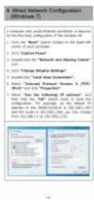

If there is any item missing or damaged, please contact the seller immediately.
1.2 Product Description
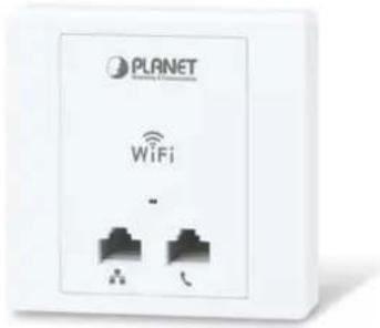
text_image
PLANET WiFi -All-in-One Manageable Wi-Fi Solution for Hospitality Industry
PLANET WNAP-W2201A enables hospitality industry to build a high-speed wireless network with a maximum data rate of 11n 300Mbps via PLANET AP controller. Furthermore, it conforms to standard 86-type electrical junction box and IEEE 802.3af PoE, suitable for in-wall installation. The WNAP-W2201A has also a built-in RJ11 port for phone pass-through and 100BASE-TX RJ45 port for Ethernet connection to such device as IPTV or laptop, enabling to integrate a hotel network with its all-in-one interface. This definitely helps guests gain good user experience.

text_image
Control It or Let It Go! PLANET WiFi AP ControllerEase of Deployment with PLANET AP Controller
To expand the capability of in-wall AP, PLANET WNAP-W2201A comes with centralized management, enabling the hospitality industry to deploy multiple APs with a single interface of AP controller and reducing repetitive tasks including AP provisioning, AP status monitoring and AP maintenance. In addition, by connecting with PLANET WAPC AP controller series, the WNAP-W2201A comes with PoE alive check and PoE schedule features, which help hoteliers optimize their wireless network within minutes.
Wi-Fi Hotel Networking
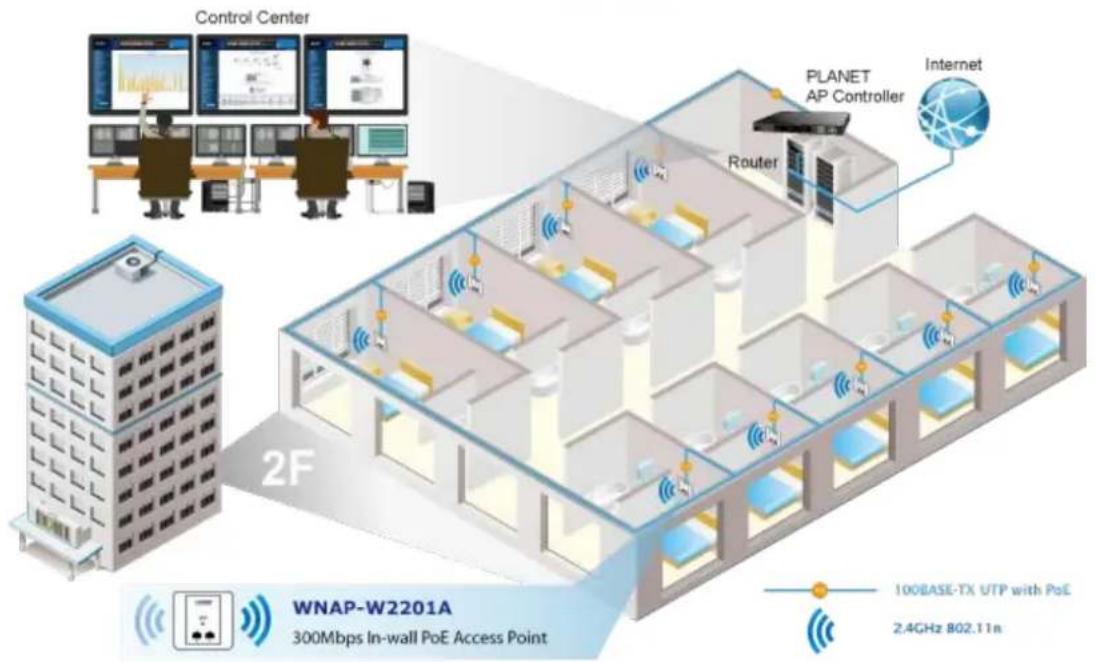
text_image
Control Center PLANET AP Controller Internet Router 2F WNAP-W2201A 300Mbps In-wall PoE Access Point 100BASE-TX UTP with PoE 2.4GHz 802.11nSuitable for Any Room Installation without Breaking Interior Design
Featuring attractive in-wall design, the WNAP-W2201A can be firmly installed into the wall via the standard 86 x 86 mm or 75 x 75 mm European outlet box, which makes electrical wiring invisible and convenient for room installation without affecting the original interior design. It is ideal for hotels, residences, hospitals and more to establish wireless network.
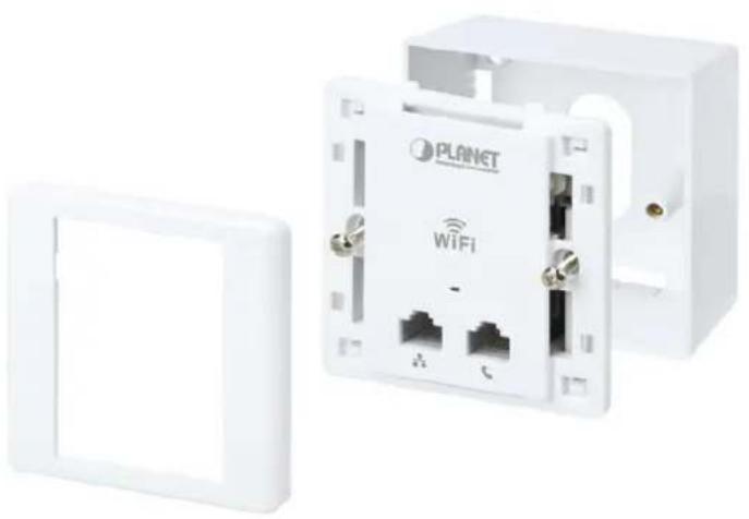
natural_image
White LAN device with Wi-Fi socket and attached wall panel, no visible text or symbols on main bodyComprehensive Wireless Operation Mode
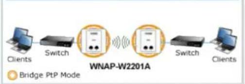
The WNAP-W2201A supports multiple wireless communication connectivities such as AP (Multi-SSIDs), Client, Repeater/Universal Repeater, WDS Point-to-Point (PtP) and WDS Point-to-Multipoint (PtMP), allowing users to comprehensively experience various applications.
AP (Multi-SSID) Mode

flowchart
graph LR
    A["Internet"] --> B["AP Mode"]
    B --> C["WNAP-W2201A"]
    C --> D["SSID-1"]
    C --> E["SSID-2"]
    D --> F["Clients"]
    E --> G["Clients"]
Client Mode

flowchart
graph LR
    A["Internet"] --> B["Wireless AP/Router"]
    B --> C["WNAP-W2201A"]
    C --> D["LAN"]
    D --> E["IP Camera"]
    F["Client Mode"] --> B
WDS Bridge-PtP Mode
flowchart
graph LR
    A["Clients"] --> B["Switch"]
    B --> C["WNAP-W2201A"]
    C --> D["Switch"]
    D --> E["Clients"]
    style C fill:#f9f,stroke:#333
    note right of C "Bridge PtP Mode"
WDS Bridge-PtMP Mode

flowchart
graph LR
    A["Client"] --> B["Switch"]
    B --> C["WNAP-W2201A Bridge PtMP Mode"]
    C --> D["AP"]
    D --> E["Switch"]
    E --> F["Clients"]
    C --> G["AP"]
    G --> H["Switch"]
    H --> I["Clients"]
WDS Repeater Mode
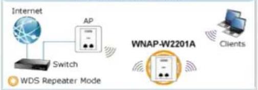
flowchart
graph LR
    A["Internet"] --> B["Switch"]
    B --> C["AP"]
    C --> D["WNAP-W2201A"]
    D --> E["Clients"]
    F["WDS Repeater Mode"] --> B
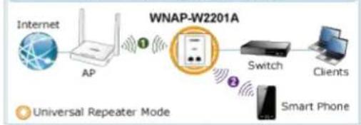
Universal Repeater Mode
flowchart
graph LR
    A["Internet"] --> B["AP"]
    B --> C["Switch"]
    C --> D["Clients"]
    C --> E["Smart Phone"]
    style A fill:#f9f,stroke:#333
    style B fill:#ccf,stroke:#333
    style C fill:#cfc,stroke:#333
    style D fill:#fcc,stroke:#333
    style E fill:#cff,stroke:#333

Easy to Install and Manage
Integrated with RJ11 phone pass-through, RJ45 Ethernet connection and IEEE 802.3af PoE PD scheme, the WNAP-W2201A is easy to be installed to any room's existing 86-type or 75-type junction box with only 6 steps. The setup wizard and on-line help can simplify the configuration even for a user who has never experienced in setting up a wireless network. In aspect of centralized management, besides the SNMP, multiple devices can be configured and monitored by PLANET AP controller. The WNAP-W2201A helps the system administrator overcome the difficulties of wireless deployment.
Easy 6-Step Installation

Dismantle the existing panel in the wall

natural_image
Illustration of a hand holding a screwdriver with a red arrow indicating rotation, next to an open electrical outlet (no text or symbols)
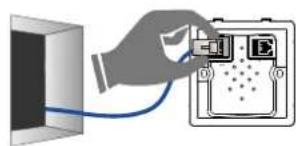
Connect network cable to the PoE Port
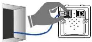
natural_image
Illustration of a hand inserting a cable into an electronic device (no text or symbols visible)
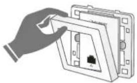
Connect Phone wire to the RJ11 Port
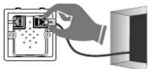
natural_image
Illustration of a hand inserting a cable into a device panel (no text or symbols visible)
Open the front panel
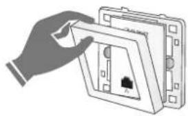
natural_image
Illustration of a hand placing a component into an open electrical socket (no text or symbols visible)
Screw the AP on the wall

text_image
Diagram showing a hand holding a screwdriver connected to a device labeled 'PUBET' with a red arrow indicating rotation.
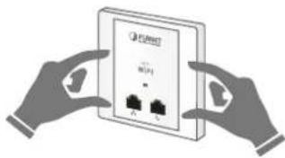
Place the front panel over AP to tightly close, and turn it on
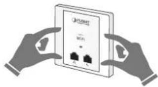
natural_image
Illustration of two hands holding a device with three ports, no text or symbols visible1.3 Product Features
Standard Compliant Hardware Interface
■ Compliant with IEEE 802.11n wireless technology with data rate of up to 300Mbps
■ One 10/100BASE-TX port and one PoE powered device (PD) port
■ One RJ11 port for phone line connection
■ European 86-type and 75-type wall outlet compatibility
Secure Network Connection
■ Advanced security: 64-/128-bit WEP, WPA/WPA2 and WPA-PSK/WPA2-PSK (TKIP/AES encryption), 802.1x
■ Supports wireless MAC address filtering control to limit the connected wireless clients
Comprehensive Wireless Advanced Features
■ Multiple operation modes including AP (Multi-SSIDs), Client, Repeater/Universal Repeater, WDS Point-to-Point (PtP) and WDS Point-to-Multipoint (PtMP)
■ Up to 5 multiple-SSIDs to allow users to access different networks through a single AP
■ Supports WMM (Wi-Fi Multimedia) and wireless QoS to enhance the efficiency of multimedia application
■ Supports IAPP (Inter Access Point Protocol) wireless roaming to enable clients to roam across multiple APs
■ Provides 5-level Transmit Power Control to adapt various environments
■ Wireless schedule allows administrators to enforce time-based internet access
■ Self-healing (Schedule Reboot) mechanism for reliable connection
Easy Deployment & Centralized Management
■ Supports AP controller to enable administrator to configure and monitor multiple APs simultaneously
■ Flexible deployment with standard 802.3af PoE/PD supported
■ Stylish in-wall design perfectly matches the room decoration
■ Step-by-step configuration with intelligent setup wizard and graphical Web-based UI
■ Supports SNMP-based management interface
■ System status monitoring including associated client list and system log
1.4 Product Specifications
| Product | WNAP-W2201A300Mbps 802.11n Wireless In-wall PoE Access Point | |
| Hardware Specifications | ||
| Interface | PoE Port | 1 x 10/100Mbps auto MDI/MDI-X RJ45 port (rear panel)※ IEEE 802.3af PoE PD Port |
| LAN Port 1 x 10/100Mbps auto MDI/MDI-X RJ45 port | ||
| RJ11 Port Connect to the telephone through the 4-conductor phone line | ||
| PoE 802.3af PoE PD, Class 3 | ||
| Antenna Built-in 3dBi antenna x 2 | ||
| Reset Button | Reset button on side panel(Press over 5 seconds to reset the device to factory default) | |
| LED Indicators PWR/SYS LED | ||
| Material Plastic | ||
| Dimensions (W x D x H) | 86 x 35 x 86 mm | |
| Weight 76g | ||
| Power Requirements 802.3af/at PoE, 48-56V DC input, 0.35A (max.) | ||
| Power Consumption < 10W | ||
| Wireless interface Specifications | ||
| Standard Compliant with | IEEE 802.11b/g/n | |
| Frequency Band | Europe -- ETSI: 2.412~2.472GHz | |
| Operating Channel | Europe -- ETSI: 1~13 | |
| Channel Width | 20 or 20/40MHz | |
| Data Transmission Rates | 802.11n (HT40): 270/243/216/162/108/81/54/27Mbps135/121.5/108/81/54/40.5/27/13.5Mbps (dynamic)802.11n (HT20): 130/117/104/78/52/39/26/13Mbps65/58.5/52/39/26/19.5/13/6.5Mbps (dynamic)802.11g: 54/48/36/24/18/12/9/6Mbps (dynamic)802.11b: 11/5.5/2/1Mbps (dynamic) | |
| Transmission Distance | 802.11n: up to 70m802.11g: up to 30mThe estimated transmission distance is based on the theory.The actual distance will vary in different environments. | |
| Max. RF Power | 802.11n: 17 ± 2dBm802.11g: 17 ± 2dBm802.11b: 18 ± 2dBm | |
| Receiver Sensitivity | IEEE 802.11b: -92dBm @ 1Mbps; -85dBm @ 11Mbps, PER < 8%IEEE 802.11g: -88dBm @ 6Mbps; -73dBm @ 54Mbps, PER <10%IEEE 802.11n: -90dBm @ MCS8; -70dBm @ MCS15, PER <10% | |
| Data Rate | IEEE 802.11b: 1/2/5.5/11MbpsIEEE 802.11g: 6/9/12/18/24/36/48/54MbpsIEEE 802.11n: 300 Mbps in 40MHz mode/150Mbps in 20MHz mode | |
| TX Power | Provides 5-level Tx Power Control (100%, 70%, 50%, 35%, 15%) | |
| Wireless Management Features | |
| Operation Mode | ■ Standalone AP■ Managed AP |
| Wireless Mode | ■ AP (Multiple-SSIDs)■ Client■ Repeater (WDS+AP)■ Universal Repeater (AP+Client)■ WDS PtP Bridge■ WDS PtMP Bridge |
| Encryption Security | ■ WEP (64-/128-bit) encryption security■ WPA/WPA2 (TKIP/AES)■ WPA-PSK/WPA2-PSK (TKIP/AES)■ 802.1x RADIUS Authentication |
| Wireless Security | Wireless MAC address filtering (up to 20 entries) |
| Supports WPS (Wi-Fi Protected Setup) | |
| SSID broadcast and hide | |
| Wireless Advanced | Supports WMM (Wi-Fi Multimedia) for better data transmission of video or on-line demand |
| Supports wireless schedule | |
| Multiple SSIDs: up to 5 | |
| Wireless Isolation: Enables it to isolate each connected wireless client of a BSSID from communicating with each other | |
| IAPP (Inter Access Point Protocol): 802.11f wireless roaming | |
| Provides wireless statistics, max. associated station number | |
| Max. Supported Clients | Wired: 2532.4GHz Wireless: 32 |
| LAN | Built-in DHCP server supporting static IP address distribution |
| Supports static IP and dynamic IP | |
| Supports UPnP | |
| Supports 802.1d Spanning Tree | |
| System Management | Web-based (HTTP) management interface |
| Supports SNTP synchronization | |
| Easy firmware upgrade via HTTP/TFTP (through AP controller) | |
| Easily locate deployed APs through the LED control | |
| Supports SNMP management, LED On/Off control, Schedule Reboot | |
| Supports Smart Discovery Utility, System Log | |
| Supports WAPC series of AP controllers for central management | |
| Max. WDS Peers 8 | |
| IEEE Standards | IEEE 802.11n (2T2R, up to 300Mbps)IEEE 802.11gIEEE 802.11bIEEE 802.11iIEEE 802.3 10BASE-TIEEE 802.3u 100BASE-TXIEEE 802.3x flow control |
| Other Protocols and CSMA/CA, CSMA/CD, TCP/IP, DHCP, ICMP, SNTP | |
| Standards | |
| Environment & Certification | |
| Temperature | Operating: -10 ~ 50 degrees CStorage: -40 ~ 70 degrees C |
| Humidity | Operating: 10 ~ 90% (non-condensing)Storage: 5 ~ 90% (non-condensing) |
| Regulatory CE, RoHS | |
Chapter 2. Hardware Introduction
2.1 Product Outlook
■ Dimensions: 86 x 35 x 86 mm
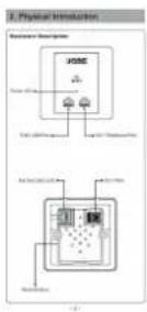
2.1.1 Panel Layout
The front and rear panels provide a simple interface monitoring the AP.
Front Panel

text_image
PLANET Networking & Communication WiFi Power LED RJ45 LAN Port RJ11 Telephone PortFigure 2-1 WNAP-W2201A Front Panel
Rear Panel

text_image
PoE Port (802.3af) RJ11 Port PoE LAN RJ11 Reset ButtonFigure 2-2 WNAP-W2201A Rear Panel
2.1.2 Hardware Description
LED Definition
| LED COLOR STATUS FUNCTION | |||
| PWR | Green | On | Device power on |
| Green | Flash | Detect and identify the LED (controlled by S/W) | |
| Green | Off | Device power off (controlled by S/W) | |
Button definition
| Object Description | |
| Reset | Press the Reset button for over 5 seconds and then release it to restore system to the factory default settings. |
H/W Interface definition
| Object Description | |
| PoE Port(802.3af/at PoE) | 10/100bps RJ45 port, auto MDI/ MDI-XConnect PoE port to the IEEE 802.3af/at PoE switch to power on the device. |
| LAN Port | 10/100Mbps RJ45 port, auto MDI/ MDI-XConnect this port to the network equipment. |
| RJ11 Port | Connect to the telephone through the 4-conductor RJ11 phone line |
Chapter 3. Hardware Installation
3.1 Installing the AP
Before installing the AP, make sure your PoE switch is connected to the Internet through the broadband service successfully at this moment. If there is any problem, please contact your local ISP. After that, please install the AP according to the following steps. Don't forget to pull out the power plug and keep your hands dry.
3.1.1 Installing the AP - WNAP-W2201A
Step 1. Follow the figure below to install WNAP-W2201A.
Easy 6-Step Installation
1 Dismantle the existing panel in the wall

natural_image
Illustration of a hand using a screwdriver to switch a wall-mounted socket (no text or symbols present)② Connect network cable to the PoE Port
natural_image
Illustration of a hand connecting a cable to an electronic device with a display panel (no text or symbols visible)3 Connect Phone wire to the RJ11 Port

natural_image
Illustration of a hand inserting a cable into a device panel (no text or symbols visible)4 Open the front panel
natural_image
Illustration of a hand inserting a socket into a wall-mounted device (no text or symbols visible)5 Screw the AP on the wall

text_image
Diagram showing a hand inserting a cable into an WiFi socket, with a red arrow indicating the cable's rotation.6 Place the front panel over AP to tightly close, and turn it on
natural_image
Illustration of two hands holding a device with two ports, no text or symbols visibleFigure 3-1 WNAP-W2200 Installation Diagram 1
※ The Ethernet cable should not exceed 8cm in length from the end connecting to PoE port to the part that goes through the outlet box.

flowchart
graph LR
    A["PLANET Wireless AP Controller with 8-Port 802.3s PoE"] --> B["PoE Switch"]
    B --> C["European 86 x 86mm Outlet Box"]
    C --> D["Ethernet Cable (Data+Power)"]
    D --> E["RJ11 Cable"]
    E --> F["WNAP-W2201A"]
    F --> G["Outer Cover"]
    H["To PBX"] --> I["To PoE Switch"]
    J["To PoE Port"] --> K["Screws"]
Step 2. Follow the figure below to connect the network devices.

flowchart
graph TD
    A["Laptop"] -->|Wireless Connection| B["WNAP-W2201A"]
    C["Laptop"] -->|Ethernet Cable (Data)| B
    B --> D["Phone"]
    B --> E["Telephone Pass-through"]
    style A fill:#f9f,stroke:#333
    style C fill:#f9f,stroke:#333
    style B fill:#ccf,stroke:#333
    style D fill:#dfd,stroke:#333
    style E fill:#dfd,stroke:#333
Figure 3-3 WNAP-W2201A Installation Diagram 3
Chapter 4. Connect to the AP
This chapter will show you how to configure the basic functions of your AP within minutes.

A computer with wired Ethernet connection to the Wireless AP is required for the first-time configuration.
4.1 System Requirements
■ Broadband Internet Access Service (Cable/xDSL/Ethernet connection)
One IEEE 802.3af/at PoE switch (supply power to the WNAP-W2201A)
■ PCs with a working Ethernet adapter and an Ethernet cable with RJ45 connectors
■ PCs running Windows XP, Windows Vista, Win 7, Win8, Win10, MAC OS 9 or later, Linux, UNIX or other platforms compatible with TCP/IP protocols

- The AP in the following instructions refers to PLANET WNAP-W2201A.
- It is recommended to use Internet Explore 8.0 or above to access the AP.
4.2 Manual Network Setup -- TCP/IP Configuration
The default IP address of the WNAP-W2201A is 192.168.1.253. And the default Subnet Mask is 255.255.255.0. These values can be changed as you want. In this guide, we use all the default values for description.
Connect the WNAP-W2201A with your PC by an Ethernet cable plugging in LAN port on one side and in LAN port of PC on the other side. Please power on the WNAP-W2201A by PoE switch through the PoE port.
In the following sections, we'll introduce how to install and configure the TCP/IP correctly in Windows 7. And the procedures in other operating systems are similar. First, make sure your Ethernet Adapter is working, and refer to the Ethernet adapter manual if needed.
4.2.1 Configuring the IP Address Manually
Summary:
■ Set up the TCP/IP Protocol for your PC.
- Configure the network parameters. The IP address is 192.168.1.xxx (If the default IP address of the WNAP-W2201A is 192.168.1.253, and the DSL router is 192.168.1.254, the "xxx" can be configured to any number from 1 to 252.) and subnet mask is 255.255.255.0.
1 Select Use the following IP address, and then configure the IP address of the PC.
2 For example, as the default IP address of the WNAP-W2201A is 192.168.1.253 and the DSL router is 192.168.1.254, you may choose from 192.168.1.1 to 192.168.1.252.

text_image
Internet Protocol Version 4 (TCP/IPv4) Properties General You can get IP settings assigned automatically if your network supports this capability. Otherwise, you need to ask your network administrator for the appropriate IP settings. Obtain an IP address automatically Use the following IP address: IP address: 192 . 168 . 1 . 100 Subnet mask: 255 . 255 . 255 . 0 Default gateway: . Obtain DNS server address automatically Use the following DNS server addresses: Preferred DNS server: . Alternate DNS server: . Advanced... OK CancelFigure 4-1 TCP/IP Setting
Now click OK to save your settings.
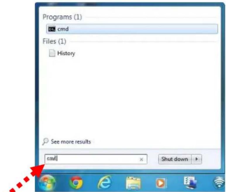
Now, you can run the ping command in the command prompt to verify the network connection between your PC and the AP. The following example is in Windows 7 OS. Please follow the steps below:
- Click on Start > Run.
2. Type "cmd" in the Search box.
text_image
Programs (1) cmd Files (1) History See more results cmd Shut downFigure 4-2 Windows Start Menu
3. Open a command prompt, type ping 192.168.1.253 and then press Enter.
If the result displayed is similar to Figure 4-3, it means the connection between your PC and the AP has been established well.
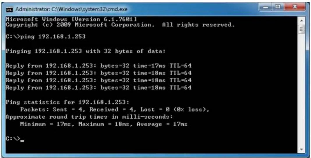
text_image
Microsoft Windows [Version 6.1.7601] Copyright (c) 2009 Microsoft Corporation. All rights reserved. C:\>ping 192.168.1.253 Pinging 192.168.1.253 with 32 bytes of data: Reply from 192.168.1.253: bytes=32 time=17ms TTL=64 Reply from 192.168.1.253: bytes=32 time=18ms TTL=64 Reply from 192.168.1.253: bytes=32 time=18ms TTL=64 Reply from 192.168.1.253: bytes=32 time=18ms TTL=64 Ping statistics for 192.168.1.253: Packets: Sent = 4, Received = 4, Lost = 0 (0% loss), Approximate round trip times in milli-seconds: Minimum = 17ms, Maximum = 18ms, Average = 17ms C:\>Figure 4-3 Successful Result of Ping Command
If the result displayed is similar to Figure 4-4, it means the connection between your PC and the AP has failed.
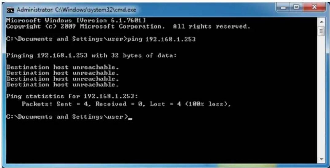
text_image
Microsoft Windows [Version 6.1.7601] Copyright (c) 2009 Microsoft Corporation. All rights reserved. C:\Documents and Settings\user>ping 192.168.1.253 Pinging 192.168.1.253 with 32 bytes of data: Destination host unreachable. Destination host unreachable. Destination host unreachable. Destination host unreachable. Ping statistics for 192.168.1.253: Packets: Sent = 4, Received = 0, Lost = 4 (100% loss), C:\Documents and Settings\user>Figure 4-4 Failed Result of Ping Command
If the address is 0.0.0.0, check your adapter installation, security settings, and the settings on your AP. Some firewall software programs may block a DHCP request on newly installed adapters.
4.3 Starting Setup in the Web UI
It is easy to configure and manage the AP with the web browser.
Step 1. To access the configuration utility, open a web-browser and enter the default IP address http://192.168.1.253 in the web address field of the browser.

text_image
http://192.168.1.253/ 192.168.1.253 File Edit View Favorites Tools HelpFigure 4-5 Login by Default IP Address
After a moment, a login window will appear. Enter admin for the User Name and Password, both in lower case letters. Then click OK or press the Enter key.

text_image
Windows Security The server 192.168.1.253 is asking for your user name and password. The server reports that it is from WNAP-W2201A. Warning: Your user name and password will be sent using basic authentication on a connection that isn't secure. admin ...... Remember my credentials OK CancelFigure 4-6 Login Window
Default IP Address: 192.168.1.253
Default User Name: admin
Default Password: admin

If the above screen does not pop up, it may mean that your web browser has been set to a proxy. Go to Tools menu> Internet Options> Connections> LAN Settings on the screen that appears, uncheck Using Proxy and click OK to finish it.
Chapter 5. Configuring the AP
This chapter delivers a detailed presentation of AP's functionalities and features the main items below, allowing you to manage the AP with ease.
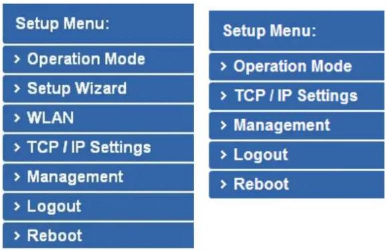
text_image
Setup Menu: > Operation Mode > Setup Wizard > WLAN > TCP / IP Settings > Management > Logout > Reboot Setup Menu: > Operation Mode > TCP / IP Settings > Management > Logout > RebootStandalone AP Mode Managed AP Mode
Figure 5-1 Main Menu
During operation, if you are not clear about a certain feature, you can refer to the "Help" section at the right side of the screen to read all the related helpful information.
5.1 Operation Mode
The Operation Mode section guides you to configuring the WNAP-W2201A to Standalone AP or Managed AP. When switching the operation mode to Managed AP, the administrator will be able to manage the AP by PLANET Wireless AP Controller. To configure the managed AP by PLANET Wireless AP Controller, please refer to the WAPC-1232HP/WAPC-2864HP AP Management user's manual.

text_image
Setup Menu: > Operation Mode > Setup Wizard > WLAN > TCP / IP Settings > Management > Logout > Reboot Operation Mode AP Operation mode configuration is used to configure the managed AP administrative mode. ○ Standalone AP In Mode Standalone AP, the AP acts as an individual AP in the network, and you manage it by using the Administrator Web User Interface (UI), or SNMP. ○ Managed AP In Mode Managed AP, the AP is part of the PLANET Wireless AP controller System, and you manage it by using the WAPC Wireless Switch. □ AP Controller IP Address 0.0.0.0 Note: After you configure the settings on the AP Operation Mode page, you must click Apply button to apply the changes and to save the settings. Changing some settings might cause the AP to stop and restart system processes. If this happens, wireless clients will temporarily lose connectivity. We recommend that you change AP settings when WLAN traffic is low. Operation Mode Standalone AP In Standalone AP, the AP acts as an individual AP in the network, and you manage it by using the Administrator Web User Interface (UI), or SNMP. Managed AP In Managed AP, the AP is part of the PLANET Wireless AP controller System, and you manage it by using the WAPC Wireless Switch.Figure 5-2 Operation Mode
The page includes the following fields:
| Object Description | |
| Standalone AP | In Standalone AP, the AP acts as an individual AP in the network, and you manage it by using the Administrator Web User Interface (UI), or SNMP. |
| Managed AP | In Managed AP, the AP is part of the PLANET Wireless AP controller System, and you manage it by using the WAPC Wireless AP controller. |
| AP Controller IP Address | Check this option and enter the IP address of the AP controller that user specifies. The default “0.0.0.0” means any AP controller existed in the local network can control this AP. |
| Apply Change | Click “Apply Change” to save and apply the settings. |
| Reset | Click “Reset” to erase all settings. |

After you configure the settings on the AP Operation Mode page, you must click Apply to apply the changes and to save the settings. Changing some settings might cause the AP to stop and restart system processes. If this happens, wireless clients will temporarily lose connectivity. We recommend that you change AP settings when WLAN traffic is low.

Please back up the configuration settings before switching from the Standalone AP mode to the Managed AP mode.
All the configurations will be erased and at the same time, the system will return to the factory default settings once it is reverted to the Standalone AP mode.
5.2 Setup Wizard
The Setup Wizard will guide the user to configuring the WNAP-W2201A easily and quickly. Select Setup Wizard on the left side of the screen and by clicking on Next on the Setup Wizard screen shown below, you will then name your WNAP-W2201A and set up its security.
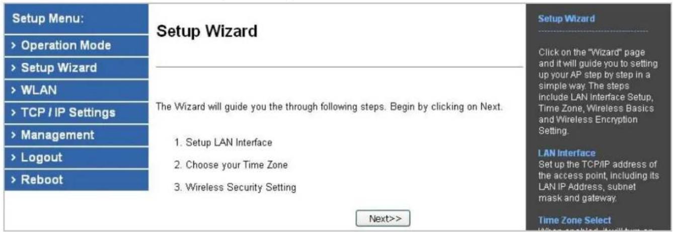
text_image
Setup Menu: > Operation Mode > Setup Wizard > WLAN > TCP / IP Settings > Management > Logout > Reboot Setup Wizard The Wizard will guide you the through following steps. Begin by clicking on Next. 1. Setup LAN Interface 2. Choose your Time Zone 3. Wireless Security Setting Next>> Setup Wizard Click on the "Wizard" page and it will guide you to setting up your AP step by step in a simple way. The steps include LAN Interface Setup, Time Zone, Wireless Basics and Wireless Encryption Setting. LAN Interface Set up the TCP/IP address of the access point, Including its LAN IP Address, subnet mask and gateway. Time Zone SelectFigure 5-3 Setup Wizard
Step 1. LAN Interface Setup

text_image
PC PoE Switch Default IP: 192.168.1.253Figure 5-4 LAN Interface Setup Topology

text_image
LAN Interface Setup IP Address: 192.168.1.253 Subnet Mask: 255.255.255.0 Default Gateway: 192.168.1.254 Cancel <Figure 5-5 Wizard – LAN Interface Setup
The page includes the following fields:
| Object Description | |
| IP Address | Displays the current IP address of the AP. (Default = 192.168.1.253) |
| Subnet Mask | Displays LAN mask of the AP. (Default = 255.255.255.0) |
| Default Gateway | IP address of the associated router. (Default = 192.168.1.254) |
Step 2. Time Zone Setting

flowchart
graph TD
    A["NTP Server"] --> B["Internet"]
    B --> C["NTP Client"]
    C --> B
    B --> A
    style A fill:#f9f,stroke:#333
    style B fill:#ccf,stroke:#333
    style C fill:#cfc,stroke:#333
Figure 5-6 Time Zone Setup Topology
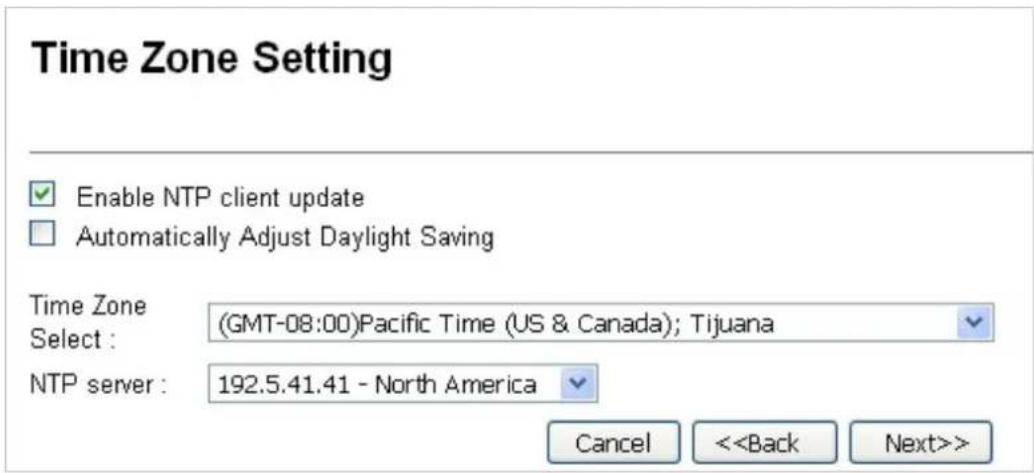
text_image
Time Zone Setting Enable NTP client update Automatically Adjust Daylight Saving Time Zone Select : (GMT-08:00)Pacific Time (US & Canada); Tijuana NTP server : 192.5.41.41 - North America Cancel <Figure 5-7 Wizard – Time Zone Setup
The page includes the following fields:
| Object Description | |
| Enable NTP Client Update | Check this box to connect NTP Server and synchronize internet time. |
| Automatically AdjustDaylight Saving | Check this box and system will adjust the daylight saving automatically. |
| Time Zone Select | Select the Time Zone from the drop-down menu. |
| NTP Server | Select the NTP Server from the drop-down menu. |
| Enable NTP Client Update | Check this box to connect NTP Server and synchronize internet time. |
Step 3. Wireless Basic Settings
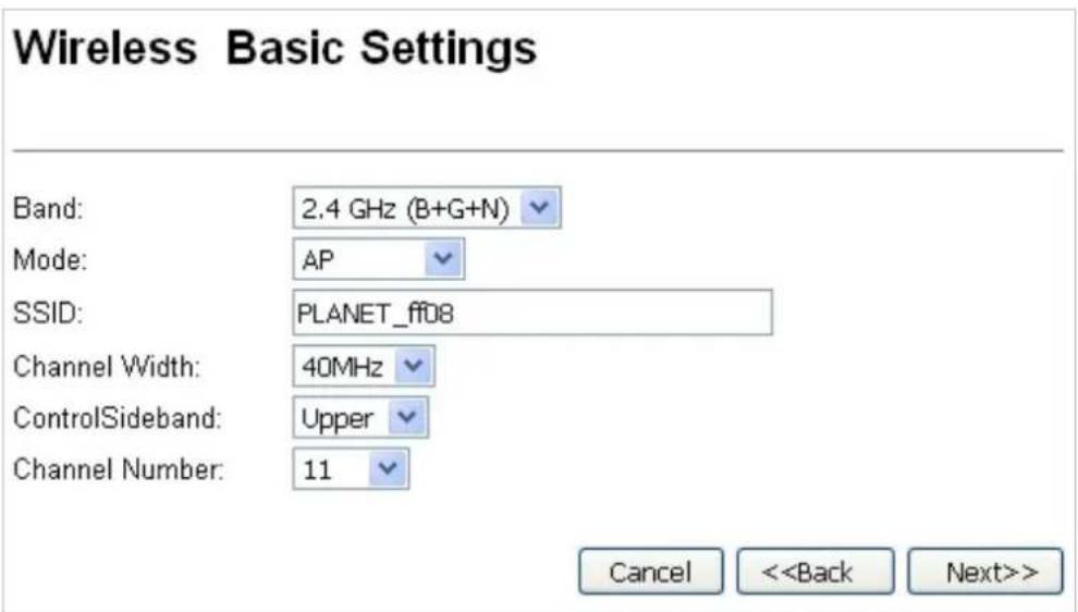
text_image
Wireless Basic Settings Band: 2.4 GHz (B+G+N) Mode: AP SSID: PLANET_ff08 Channel Width: 40MHz ControlSideband: Upper Channel Number: 11 Cancel <Figure 5-8 Wizard – Wireless Basic Settings
The page includes the following fields:
| Object Description | |
| Band | Supports 802.11b, 802.11g, 802.11n and mixed mode. Please choose its band according to your clients. |
| Mode | Supports AP, Client, WDS and AP+WDS mode. |
| SSID | Service Set Identifier identifies your wireless network. |
| Channel Width | Select 40MHz if you use 802.11n, otherwise, 20MHz is for the 802.11b/g mode. |
| Control Sideband | It is only valid when you choose a 40MHz channel width. |
| Channel Number | Indicates the channel setting for the AP. |
Step 4. Wireless Security Settings
Secure your wireless network by turning on the WPA or WEP security feature on the router. For this section, you can set WEP and WPA-PSK security mode.
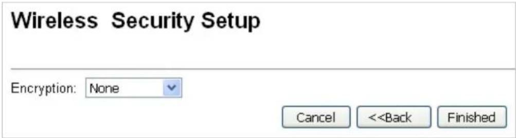
text_image
Wireless Security Setup Encryption: None Cancel <■ Encryption: WEP
The following picture shows how to set the WEP security. text_image
Wireless Security Setup Encryption: WEP Key Length: 64-bit Key Format: Hex (10 characters) Key Setting: ********** Cancel <| Object Description | |
| Key Length | WEP supports 64-bit or 128-bit security key. |
| Key Format | User can enter key in ASCII or Hex format. |
| Key Setting | Enter the key whose format is limited by the key format, ASCII or Hex. |
■ Encryption: WPA-PSK
The following picture shows how to set WPA-PSK security. You can select WPA (TKIP), WPA2 (AES) and Mixed mode. text_image
Wireless Security Setup Encryption: WPA2(AES) Pre-Shared Key Format: Passphrase Pre-Shared Key: Cancel <| Object Description | |
| Pre-shared Key Format | Specify the format of the key, pass phrase or hex. |
| Pre-shared Key | Enter the key whose format is limited by the key format. |
5.3 TCP/IP Settings
This page is used to configure the parameters for local area network which connects to the LAN port of your AP. Here you may change the setting for IP address, subnet mask, DHCP, etc.5.3.1 LAN Settings
On the LAN Settings page, you can configure the IP parameters of the LAN on the screen as shown below.LAN Interface Setup
This page is used to configure the parameters for local area network which connects to the LAN port of your Access Point. Here you may change the setting for IP address, subnet mask, DHCP, etc.. The system will reboot immediately after clicking "Apply Changes" - In DHCP mode or change in IP address. flowchart
graph LR
    PC["PC"] -->|Data Link| PoESwitch["PoE Switch"]
    PoESwitch -->|Default IP: 192.168.1.253| Device["Device"]
    style PC fill:#f9f,stroke:#333
    style PoESwitch fill:#ccf,stroke:#333
    style Device fill:#cfc,stroke:#333
text_image
IP Address: 192.168.1.253 Subnet Mask: 255.255.255.0 Default Gateway: 192.168.1.254 DHCP: Client DHCP Client Range: 192.168.1.100 - 192.168.1.200 Show Client DHCP Lease Time: 480 (1 ~ 10080 minutes) Static DHCP: Set Static DHCP Domain Name: Planet 802.1d Spanning Tree: Disabled Clone MAC Address: 000000000000 UPnP Enable: Enabled Apply Changes Reset| Object Description | |
| IP Address | The default LAN IP address of the WNAP-W2201A is 192.168.1.253.You can change it according to your request. |
| Subnet Mask | Default is 255.255.255.0. You can change it according to your request. |
| Default Gateway | Default is 192.168.1.254. You can change it according to your request. |
| DHCP | You can select a Disabled, Client, and Server. Default is Client, meaning the WNAP-W2201A must be connected to a router to assign IP addresses. |
| DHCP Client Range | For the Server mode, you must enter the DHCP client IP address range in the field. And you can click “Show Client” to show the Active DHCP Client Table. |
| Static DHCP | Click “Set Static DHCP” and you can reserve some IP addresses for those network devices with the specified MAC addresses anytime when they request IP addresses. |
| Domain Name | Default is Planet. |
| 802.1d Spanning Tree You | can enable or disable the Spanning Tree function. |
| Clone MAC Address You | can input an MAC address here for using clone function. |
| UPnP Enable | You can enable or disable the UPnP function. The UPnP feature allows the devices, such as Internet computers, to access the local host resources or devices as needed. UPnP devices can be automatically discovered by the UPnP service application on the LAN. |
5.4 WLAN
The Wireless menu contains submenus of the settings about wireless network. Please refer to the following sections for the details. text_image
WLAN > Basic Settings > Advanced Settings > RF Output Power > Security > Access Control > WDS Settings > Site Survey > WPS > Schedule5.4.1 Basic Settings
Choose menu "WLAN → Basic Settings" to configure the basic settings for the wireless network on this page. After the configuration is done, please click "Apply Changes" to save the settings. First of all, the wireless AP supports multiple wireless modes for different network applications, which include: AP ■ Multiple SSIDs ■ Universal Repeater ■ Client WDS ■ Repeater It is so easy to combine the WNAP-W2201A with the existing wired network. The WNAP-W2201A definitely provides a total network solution for the home and the SOHO users.  Standard Access PointAP (Multi-SSID) Mode
Internet   AP Mode  WNAP-W2201A SSID-1 SSID-2   Clients   ClientsWireless Basic Settings
This page is used to configure the parameters for wireless LAN clients which may connect to your Access Point. Here you may change wireless encryption settings as well as wireless network parameters.  Disable Wireless LAN Interface Band: 2.4 GHz (B+G+N)  Mode: AP  MultipleAP Network Type: Infrastructure SSID: PLANET\_ff08 Channel Width: 40MHz Control Sideband: Upper Channel Number: 11 Broadcast SSID: Enabled VMMM: Enabled Data Rate: Auto TX restrict: 0 Mbps (0:no restrict) RX restrict: 0 Mbps (0:no restrict) Associated Clients: Show Active Clients  Enable Mac Clone (Single Ethernet Client)  Enable Universal Repeater Mode (Acting as AP and client taneously) SSID of Extended Interface: Planet Rpt0 Add to Profile Add to Profile Figure 5-14 Wireless Basic Settings – AP The page includes the following fields:| Object Description | |
| Disable Wireless LAN Interface | Check the box to disable the wireless function. |
| Band | Select the desired mode. Default is “2.4GHz (B+G+N)”. It is strongly recommended that you set the Band to “2.4GHz (B+G+N)”, and all of 802.11b, 802.11g, and 802.11n wireless stations can connect to the WNAP-W2201A.■ 2.4 GHz (B): 802.11b mode, rate is up to 11Mbps■ 2.4 GHz (G): 802.11g mode, rate is up to 54Mbps■ 2.4 GHz (N): 802.11n mode, rate is up to 300Mbps(2T2R)■ 2.4 GHz (B+G): 802.11b/g mode, rate is up to 11Mbps or 54Mbps■ 2.4 GHz (G+N): 802.11g/n mode, rate is up to 54Mbps or 300Mbps■ 2.4 GHz (B+G+N): 802.11b/g/n mode, rate is up to 11Mbps, 54Mbps, or 300Mbps |
| Mode | There are four kinds of wireless mode selections:■ AP■ Client■ WDS■ RepeaterIf you select WDS or Repeater, please click “WDS Settings” in the submenu for the related configuration. Furthermore, click “Multiple AP” to enable multiple SSID functions. |
| SSID | It’s the ID of the wireless network. User can access the wireless network via the ID only. However, if you switch to Client Mode, this field becomes the SSID of the AP you want to connect with.Default: PLANET_XXXX (“X” means the last 4 digits of the MAC address) |
| Channel Width | You can select 20MHz, or 40MHz. |
| Channel Number | You can select the operating frequency of wireless network.Default: 11 |
| Broadcast SSID | If you enable “Broadcast SSID”, every wireless station located within the coverage of the AP can discover its signal easily. If you are building a public wireless network, enabling this feature is recommended. In private network, disabling “Broadcast SSID” can provide better wireless network security.Default is “Enabled”. |
| Data Rate | Set the wireless data transfer rate to a certain value. Since most of wireless devices will negotiate with each other and pick a proper data transfer rate automatically, it’s not necessary to change this value unless you know what will happen after modification.Default is “Auto”. |
| Associated Clients | Click “Show Active Clients” to show the status table of active wireless clients. |
| Enable Universal Repeater Mode(Acting as AP and client simultaneously) | Universal Repeater is a technology used to extend wireless coverage.To enable Universal Repeater mode, check the box and enter the SSID you want to broadcast in the field below. Then please click “Security” in the submenu for the related settings of the AP you want to connect with. |
multiple-SSIDs
Enabling multiple-SSIDs can broadcast multiple WLAN SSIDs using virtual interfaces. You can have different encryption settings for each WLAN and you can restrict what they have access to.AP (Multi-SSID) Mode
Internet   SSID-1  Clients SSID-2  Clients  AP Mode WNAP-W2201A Choose menu "WLAN → Basic Settings → Multiple AP" to configure the device as a general wireless access point with multiple SSIDs. text_image
Wireless Basic Settings Disable Wireless LAN Interface Band: 2.4 GHz (B+G+N) Mode: AP MultipleAP Network Type: InfrastructureMultiple APs
This page shows and updates the wireless setting for multiple APs.| No. | Enable | Band | SSID | Data Rate | Broadcast SSID | WMM | Access | Tx Restrict(Mbps) | Rx Restrict(Mbps) | Active Client List | WLAN mode |
| AP1 | 2.4 GHz (B+G+N) | PLANET_ff09 | Auto | Enabled | Enabled | LAN | 0 | 0 | Show | AP | |
| AP2 | 2.4 GHz (B+G+N) | PLANET_ffDa | Auto | Enabled | Enabled | LAN | 0 | 0 | Show | AP | |
| AP3 | 2.4 GHz (B+G+N) | PLANET_ff0b | Auto | Enabled | Enabled | LAN | 0 | 0 | Show | AP | |
| AP4 | 2.4 GHz (B+G+N) | PLANET_ff0c | Auto | Enabled | Enabled | LAN | 0 | 0 | Show | AP |
niversal Repeater
This mode allows the AP with its own BSS to relay data to a root AP to which it is associated with WDS disabled. The wireless repeater relays signal between its stations and the root AP for greater wireless range. flowchart
graph LR
    A["Internet"] --> B["AP"]
    B --> C["Switch"]
    C --> D["Clients"]
    C --> E["Smart Phone"]
    style A fill:#f9f,stroke:#333
    style B fill:#ccf,stroke:#333
    style C fill:#cfc,stroke:#333
    style D fill:#fcc,stroke:#333
    style E fill:#cff,stroke:#333
Wireless Basic Settings
This page is used to configure the parameters for wireless LAN clients which may connect to your Access Point. Here you may change wireless encryption settings as well as wireless network parameters. text_image
Disable Wireless LAN Interface Band: 2.4 GHz (B+G+N) Mode: AP Network Type: Infrastructure SSID: PLANET_ff08 Enable Mac Clone (Single Ethernet Client) Enable Universal Repeater Mode (Acting as AP and client simultaneously)Wireless Site Survey
text_image
Wireless Router Site Survey Recommended Signal Strength >70% AP| SSID | BSSID | Channel | Type | Encrypt | Signal | Select |
| WiFiRepeater-001 | 00:30:4f:91:1c:44 | 1 (B+G+N) | AP | no | 60 | |
| Default_2.4G_1 | 00:30:4f:b4:c4:a0 | 11 (B+G+N) | AP | WPA2-PSK | 52 | |
| WDRT-1200AC-2.4G | 00:30:4f:1c:7e:e4 | 6 (B+G+N) | AP | WPA2-PSK | 44 | |
| Next>> | ||||||
Wireless Site Survey
This page provides tool to scan the wireless network. If any Access Point or IBSS is found, you could choose to connect it manually when client mode is enabled. text_image
Wireless Router Recommended Signal Strength >70% Encryption: WPA Authentication Mode: WPA Cipher Suite: Pre-Shared Key Format: Pre-Shared Key: Enterprise (RADIUS) ● Personal (Pre-Shared Key) TKIP AES Passphrase <text_image
Connect successfully! Add to Wireless Profile Reboot Now Reboot Later| Wireless 2 Repeater Interface Configuration | |
| Mode | Infrastructure Client |
| SSID | Default_2.4G_1 |
| Encryption | WPA2 |
| BSSID | 00:30:4f:b4:c4:a0 |
| State | Connected |
■ ient (Infrastructure)
Combine the Wireless Router to the Ethernet devices such as TV, Game player, or HDD and DVD, to make them be wireless stations. flowchart
graph LR
    A["Internet"] --> B["Wireless AP/Router"]
    B --> C["WNAP-W2201A"]
    C --> D["IP Camera"]
    style A fill:#f9f,stroke:#333
    style B fill:#ccf,stroke:#333
    style C fill:#cfc,stroke:#333
    style D fill:#fcc,stroke:#333
Wireless Basic Settings
This page is used to configure the parameters for wireless LAN clients which may connect to your Access Point. Here you may change wireless encryption settings as well as wireless network parameters. text_image
Disable Wireless LAN Interface Band: 2.4 GHz (B+G+N) Mode: Client Network Type: Infrastructure MultipleAP SSID: PLANET_ff08 Channel Width: 40MHz Control Upper Sideband: Channel 11 Number: Broadcast Enabled SSID: WMM: Enabled Data Rate: Auto TX restrict: 0 Mbps (0:no restrict) RX restrict: 0 Mbps (0:no restrict) Associated Show Active Clients Clients: Enable Mac Clone (Single Ethernet Client) Enable Universal Repeater Mode (Acting as AP and client simultaneously) SSID of Extended Interface: Planet Rpt0 Add to Profile Add to Profile| Object Description | |
| Disable Wireless LAN Interface | Check the box to disable the wireless function. |
| Band | Select the desired mode. Default is “2.4GHz (B+G+N)”. It is strongly recommended that you set the Band to “2.4GHz (B+G+N)”, and all of 802.11b, 802.11g, and 802.11n wireless stations can connect to the WNAP-W2201A.■ 2.4 GHz (B): 802.11b mode, rate is up to 11Mbps■ 2.4 GHz (G): 802.11g mode, rate is up to 54Mbps■ 2.4 GHz (N): 802.11n mode, rate is up to 300Mbps(2T2R)■ 2.4 GHz (B+G): 802.11b/g mode, rate is up to 11Mbps or 54Mbps■ 2.4 GHz (G+N): 802.11g/n mode, rate is up to 54Mbps or 300Mbps■ 2.4 GHz (B+G+N): 802.11b/g/n mode, rate is up to 11Mbps, 54Mbps, or 300Mbps |
| Mode | There are four kinds of wireless mode selections:■ AP■ Client■ WDS■ RepeaterIf you select WDS or Repeater, please click “WDS Settings” in the submenu for the related configuration. Furthermore, click “Multiple AP” to enable multiple SSID functions. |
| Network Type | In Infrastructure, the wireless LAN serves as a wireless station. And the user can use the PC equipped with the WNAP-W2201A to access the wireless network via other access points. In ad hoc, the wireless LAN will use the ad-hoc mode to operate.Default is “Infrastructure”.Note: only while the wireless mode is set to “Client”, then the Network Type can be configured. |
| SSID | It’s the ID of the wireless network. User can access the wireless network via the ID only. However, if you switch to Client Mode, this field becomes the SSID of the AP you want to connect with.Default: PLANET_XXXX (“X” means the last 4 digits of the MAC address) |
| Broadcast SSID | If you enable “Broadcast SSID”, every wireless station located within the coverage of the WNAP-W2201A can discover its signal easily. If you are building a public wireless network, enabling this feature is recommended. In private network, disabling “Broadcast SSID” canprovide better wireless network security.Default is “Enabled”. |
| Data Rate | Set the wireless data transfer rate to a certain value. Since most of wireless devices will negotiate with each other and pick a proper data transfer rate automatically, it’s not necessary to change this value unless you know what will happen after modification.Default is “Auto”. |
| Enable Mac Clone (Single Ethernet Client) | Enable Mac Clone. |
Step 1. Go to the "WLAN → Site Survey" page and click "Site Survey".
Wireless Site Survey
This page provides tool to scan the wireless network. If any Access Point or IBSS is found, you could choose to connect it manually when client mode is enabled. natural_image
Illustration of a wireless device emitting sound waves (no text or symbols)bar
| Category | Value (%) | |---|---| | Bar 1 | >70% |text_image
PUBIET WiFi △ ↘| SSID | BSSID | Channel | Type | Encrypt | Signal |
| None |
Wireless Site Survey
This page provides tool to scan the wireless network. If any Access Point or IBSS is found, you could choose to connect it manually when client mode is enabled.  Site Survey| SSID | BSSID | Channel | Type | Encrypt | Signal | Select |
| WiFiRepeater-001 | 00:30:4f:91:1c:44 | 1(B+G+N) | AP | no | 60 | |
| Default_2.4G_1 | 00:30:4f:b4:c4:a0 | 11(B+G+N) | AP | WPA2-PSK | 52 | |
| WDRT-1200AC-2.4G | 00:30:4f:1c:7e:e4 | 6(B+G+N) | AP | WPA2-PSK | 44 | |
| ADN-4100_ENM | 00:30:4f:9c:a3:25 | 1(B+G+N) | AP | WPA-PSK/WPA2-PSK | 44 | |
| PLANET_11F_AP | 00:30:4f:81:ed:88 | 11(B+G+N) | AP | WPA2-PSK | 29 |
text_image
Wireless Site Survey Wireless Router Recommended Signal Strength >70% Encryption: WPA Authentication Mode: WPA Cipher Suite: Pre-Shared Key Format: Pre-Shared Key: Enterprise (RADIUS) Personal (Pre-Shared Key) TKIP AES Passphrase <text_image
Connect successfully! Add to Wireless Profile Reboot Now Reboot LaterDS
Connect this Wireless AP with up to 8 WDS-capable wireless APs to expand the scope of network. WDS Bridge-PtP Mode flowchart
graph LR
    A["Clients"] --> B["Switch"]
    B --> C["WNAP-W2201A"]
    C --> D["Switch"]
    D --> E["Clients"]
    C -->|Wireless Signal| C
flowchart
graph LR
    A["Clients"] --> B["Switch"]
    B --> C["WNAP-W2201A"]
    C --> D["AP"]
    D --> E["Switch"]
    E --> F["Clients"]
    C --> G["AP"]
    G --> H["Switch"]
    H --> I["Clients"]
    style C fill:#f9f,stroke:#333
    style D fill:#ccf,stroke:#333
    style E fill:#ccf,stroke:#333
    style F fill:#ccf,stroke:#333
    style G fill:#ccf,stroke:#333
    style H fill:#ccf,stroke:#333
    style I fill:#ccf,stroke:#333
Wireless Basic Settings
This page is used to configure the parameters for wireless LAN clients which may connect to your Access Point. Here you may change wireless encryption settings as well as wireless network parameters. text_image
Disable Wireless LAN Interface Band: 2.4 GHz (B+G+N) Mode: WDS MultipleAP Network Type: Infrastructure SSID: PLANET_ff08 Add to Profile Channel Width: 40MHz Control Upper Sideband: Channel Number: 11 Broadcast Enabled SSID: WMM: Enabled Data Rate: Auto TX restrict: 0 Mbps (0:no restrict) RX restrict: 0 Mbps (0:no restrict) Associated Show Active Clients Clients: Enable Mac Clone (Single Ethernet Client) Enable Universal Repeater Mode (Acting as AP and client simultaneously) SSID of Extended Interface: Planet Rpt0 Add to Profile| Object Description | |
| Disable Wireless LAN Interface | Check the box to disable the wireless function. |
| Band | Select the desired mode. Default is “2.4GHz (B+G+N)”. It is strongly recommended that you set the Band to “2.4GHz (B+G+N)”, and all of 802.11b, 802.11g, and 802.11n wireless stations can connect to the WNAP-W2201A.■ 2.4 GHz (B): 802.11b mode, rate is up to 11Mbps■ 2.4 GHz (G): 802.11g mode, rate is up to 54Mbps■ 2.4 GHz (N): 802.11n mode, rate is up to 300Mbps(2T2R)■ 2.4 GHz (B+G): 802.11b/g mode, rate is up to 11Mbps or 54Mbps■ 2.4 GHz (G+N): 802.11g/n mode, rate is up to 54Mbps or 300Mbps■ 2.4 GHz (B+G+N): 802.11b/g/n mode, rate is up to 11Mbps, 54Mbps, or 300Mbps |
| Mode | There are four kinds of wireless mode selections:■ AP■ Client■ WDS■ RepeaterIf you select WDS or Repeater, please click “WDS Settings” in the submenu for the related configuration. Furthermore, click “Multiple AP” to enable multiple SSID function. |
| Channel Width | You can select 20MHz, or 40MHz |
| Control Sideband | You can select Upper or Lower. |
| Channel Number | You can select the operating frequency of wireless network. |
| Data Rate | Set the wireless data transfer rate to a certain value. Since most of wireless devices will negotiate with each other and pick a proper data transfer rate automatically, it’s not necessary to change this value unless you know what will happen after modification.Default is “Auto”. |
epeater
Connect this Wireless AP with up to 8 WDS-capable wireless APs, and connect another AP to provide service for all wireless stations within its coverage. flowchart
graph LR
    A["Internet"] --> B["Switch"]
    B --> C["AP"]
    C --> D["WNAP-W2201A"]
    D --> E["Clients"]
Wireless Basic Settings
This page is used to configure the parameters for wireless LAN clients which may connect to your Access Point. Here you may change wireless encryption settings as well as wireless network parameters. text_image
Disable Wireless LAN Interface Band: 2.4 GHz (B+G+N) Mode: Repeater Network Type: Infrastructure SSID: PLANET_ff08 Channel Width: 40MHz Control Sideband: Upper Channel Number: 11 Broadcast SSID: Enabled WMM: Enabled Data Rate: Auto TX restrict: 0 Mbps (0:no restrict) RX restrict: 0 Mbps (0:no restrict) Associated Clients: Show Active Clients Enable Mac Clone (Single Ethernet Client) Enable Universal Repeater Mode (Acting as AP and client simultaneously) SSID of Extended Interface: Planet Rpt0 Add to Profile Add to Profile| Object Description | |
| Disable Wireless LAN Interface | Check the box to disable the wireless function. |
| Band | Select the desired mode. Default is “2.4GHz (B+G+N)”. It is strongly recommended that you set the Band to “2.4GHz (B+G+N)”, and all of 802.11b, 802.11g, and 802.11n wireless stations can connect to the WNAP-W2201A.■ 2.4 GHz (B): 802.11b mode, rate is up to 11Mbps■ 2.4 GHz (G): 802.11g mode, rate is up to 54Mbps■ 2.4 GHz (N): 802.11n mode, rate is up to 300Mbps(2T2R)■ 2.4 GHz (B+G): 802.11b/g mode, rate is up to 11Mbps or 54Mbps■ 2.4 GHz (G+N): 802.11g/n mode, rate is up to 54Mbps or 300Mbps■ 2.4 GHz (B+G+N): 802.11b/g/n mode, rate is up to 11Mbps, 54Mbps, or 300Mbps |
| Mode | There are four kinds of wireless mode selections:■ AP■ Client■ WDS■ RepeaterIf you select WDS or Repeater, please click “WDS Settings” in the submenu for the related configuration. Furthermore, click “Multiple AP” to enable multiple SSID functions. |
| SSID | It's the ID of the wireless network. User can access the wireless network via the ID only. However, if you switch to Client Mode, this field becomes the SSID of the AP you want to connect with.Default: PLANET_XXXX (“X” means the last 4 digits of the MAC address) |
| Channel Width | You can select 20MHz, or 40MHz |
| Control Sideband | You can select Upper or Lower. |
| Channel Number | You can select the operating frequency of wireless network. |
| Broadcast SSID | If you enable “Broadcast SSID”, every wireless station located within the coverage of the WNAP-W2201A can discover its signal easily. If you are building a public wireless network, enabling this feature is recommended. In private network, disabling “Broadcast SSID” can provide better wireless network security.Default is “Enabled”. |
| Data Rate | Set the wireless data transfer rate to a certain value. Since most of wireless devices will negotiate with each other and pick a proper data transfer rate automatically, it’s not necessary to change this value unless you know what will happen after modification.Default is “Auto”. |
| Associated Clients | Click “Show Active Clients” to show the status table of active wireless clients. |
| Enable Universal Repeater Mode (Acting as AP and client simultaneously) | Universal Repeater is a technology used to extend wireless coverage. To enable Universal Repeater Mode, check the box and enter the SSID you want to broadcast in the field below. Then please click “Security” in the submenu for the related settings of the AP you want to connect with. |
5.4.2 Advanced Settings
Choose menu "WLAN→ Advanced Settings" to configure the advanced settings for the wireless network on this page. After the configuration, please click "Apply" to save the settings.Wireless Advanced Settings
These settings are only for more technically advanced users who have a sufficient knowledge about wireless LAN. These settings should not be changed unless you know what effect the changes will have on your Access Point. text_image
Fragment Threshold: 2346 (256-2346) RTS Threshold: 2347 (0-2347) Beacon Interval: 100 (20-1024 ms) Preamble Type: Long Preamble Short Preamble IAPP: Enabled Disabled Aggregation: Enabled Disabled Short GI: Enabled Disabled WLAN Partition: Enabled Disabled STBC: Enabled Disabled LDPC: Enabled Disabled 20/40MHz Coexist: Enabled Disabled TX Beamforming: Enabled Disabled| Object Description | |
| Fragment Threshold | You can specify the maximum size of packet during the fragmentation of data to be transmitted. If you set this value too low, it will result in bad performance.Default is “2346”. |
| RTS Threshold When the | packet size is smaller than the RTS threshold, the access point will not use the RTS/CTS mechanism to send this packet.Default is “2347”. |
| Beacon Interval The interval | val of time that this access point broadcasts a beacon.Beacon is used to synchronize the wireless network. Default is “100”. |
| IAPP IAPP (Inter-Access | Point Protocol) enabled is recommended as itdescribes an optional extension to IEEE 802.11 that provides wireless access-point communications among multivendor systems.Default is “Enabled”. |
| Protection It is recommended to enable the protection mechanism. This mechanism can decrease the rate of data collision between 802.11b and 802.11g wireless stations. When the protection mode is enabled, the throughput of the AP will be a little lower due to the transmission of heavy frame traffic.Default is “Disabled”. | |
| Aggregation It is a function where the values of multiple rows are grouped together.Default is “Enabled” | |
| Short GI | It is used to set the time that the receiver waits for RF reflections to settle out before sampling data.Default is “Enabled” |
| WLAN Partition | This feature also called “WLAN isolation” or “Block Relay”. If this is enabled, wireless clients cannot exchange data through the WNAP-W2201A.Default is “Disabled”. |
| STBC | Activate Space Time Blocking Code (STBC) which does not need channel statement information (CSI).Default Setting: "Enabled" |
| LDPC | Low-density Parity-check Code is wireless data transmit algorithm.Default Setting: "Enabled" |
| 20/40MHz Coexist Configure 20/40MHz coexisting scheme.If you set up as "Enabled", "20MHz" and "40MHz" will coexist.Default Setting: "Disabled" | |
5.4.3 RF Output Power
Choose menu "WLAN2 (2.4GHz) → RF Output Power" to adjust to different levels of transmitting power for the wireless network according to various environment on this page. After the configuration, please click "Apply Changes" to save the settings.Wireless RF Output Power
RF Output Power Control provides the flexibility to control the WiFi Transmit power to optimize the wireless range. Wifi power consumption for a Access Point could be reduced to up to 75% from its peak power consumption for serving a small to medium size home, while boosted to maximum power for a large homes and businesses. The WNAP-W2201A supports output power control levels up to 5. You can change the RF output power level here depends on the various environments and signal strength. pie
| Power Level | Percentage (%) | | :--- | :--- | | 100% | 15 | | 70% | 35 | | 50% | 50 | | 35% | 70 | | 15% | 100 | RF Output Power: Apply Changes Reset5.4.4 Security
Choose menu "WLAN → Security" to configure the settings of wireless security for the wireless network on this page. After the configuration, please click "Apply Changes" to save the settings. text_image
Wireless Security Setup This page allows you setup the wireless security. Turn on WEP or WPA by using Encryption Keys could prevent any unauthorized access to your wireless network. Select SSID: Root AP - PLANET_ff08 Apply Changes Reset Internet DSL Router AP 2.4GHz Wi-Fi Network Encryption: Disable| Object Description | |
| Select SSID | Select the SSID you want to configure the wireless security function, which includes the root one and the client one. |
| Encryption | Disable:No security setup for wireless connection. |
| ■ VEP:It is based on the IEEE 802.11 standard. And the default setting of authentication is Automatic, which can select Open System or Shared Key authentication type automatically based on the wireless station's capability and request. Furthermore, you can select Key Length and enter 10 and 26 Hexadecimal digits (any combination of 0-9, a-f, A-F, zero key is not promoted) or 5 and 13 ASCII characters in the Encryption Key field. | |
| ■ VPA:WPA is a medium level encryption and is supported by most wireless devices and operating systems. | |
| ■VPA2:WPA2 is a high level encryption and is supported by most wireless devices and operating systems. | |
| ■VPA / WPA2 / WPA-Mixed:WPA Mixed Mode allows the use of both WPA and WPA2 at the same time. | |
| Authentication Mode | ■Enterprise (RADIUS)When you select the authentication mode based on Enterprise (RADIUS Server), please enter theIP Address, Port, andPasswordof the RADIUS Server. |
| ■Personal (Pre-shared Key)When you select the other authentication mode based on Personal (Pre-shared Key), please enter at least 8 ASCII characters (Passphrase) or 64 Hexadecimal characters. All of the Cipher Suites supportTKIPandAES. | |
| 802.1x Authentication | Enable 802.1x authentication function and then enter theIP Address, Port, andPasswordof the RADIUS Server. |
5.4.5 Access Control
Choose menu "WLAN → Access Control" to allow or deny the computer of specified MAC address to connect with the WNAP-W2201A on this page. After the configuration, please click "Apply Changes" to save the settings. text_image
Wireless Access Control If you choose 'Allowed Listed', only those clients whose wireless MAC addresses are in the access control list will be able to connect to your Access Point. When 'Deny Listed' is selected, these wireless clients on the list will not be able to connect the Access Point. Wireless Access Control Mode: Disable Disable MAC Address: Allow Listed Deny Listed Apply Changes Reset Current Access Control List: MAC Address Comment Select Delete Selected Delete All Reset| Object Description | |
| Wireless Access Control Mode | You can choose to set the Allow Listed, Deny Listed, or Disable this function. |
| MAC Address | Enter the MAC address you want to allow or deny connection to the WNAP-W2201A in the field. |
| Comment | You can make some comment on each MAC address on the list. |
| Current Access Control List | You can select some MAC addresses and click “Delete Selected” to delete it. |
■ Wireless Access Control example:
To deny a PC at the MAC address of 00:30:4F:00:00:01 to connect to your wireless network, do as follows: Step 1. Select "Deny Listed" from MAC Address Filter drop-down menu. Step 2. Enter 00:30:4F:00:00:01 in the MAC address box and click "Add". Step 3. Click "OK" to save your settings and you can add more MAC addresses, if you like, simply repeat the above steps.Wireless Access Control
If you choose 'Allowed Listed', only those clients whose wireless MAC addresses are in the access control list will be able to connect to your Access Point. When 'Deny Listed' is selected, these wireless clients on the list will not be able to connect the Access Point. Wireless Access Control Mode: Deny Listed  MAC Address: Comment:  Apply Changes Reset Current Access Control List: text_image
MAC Address Comment Select 00:30:4f:00:00:01 Delete Selected Delete All Reset5.4.6 WDS
WDS (Wireless Distribution System) feature can be used to extend your existing wireless network coverage. Here we present you how to configure such feature in the AP. WDS Bridge-PtP Mode flowchart
graph LR
    A["Clients"] --> B["Switch"]
    B --> C["WNAP-W2201A"]
    C --> D["Switch"]
    D --> E["Clients"]
    C -->|Signal| C
    C -->|WNR| C
flowchart
graph LR
    A["Clients"] --> B["Switch"]
    B --> C["AP"]
    C --> D["Switch"]
    D --> E["Clients"]
    C --> F["AP"]
    F --> G["Switch"]
    G --> H["Clients"]
    style A fill:#f9f,stroke:#333
    style B fill:#ccf,stroke:#333
    style C fill:#cfc,stroke:#333
    style D fill:#fcc,stroke:#333
    style E fill:#cff,stroke:#333
    style F fill:#ffc,stroke:#333
    style G fill:#fcc,stroke:#333
    style H fill:#cff,stroke:#333
flowchart
graph LR
    A["Internet"] --> B["Switch"]
    B --> C["AP"]
    C --> D["WNAP-W2201A"]
    D --> E["Clients"]
    style A fill:#f9f,stroke:#333
    style B fill:#ccf,stroke:#333
    style C fill:#cfc,stroke:#333
    style D fill:#fcc,stroke:#333
    style E fill:#ffc,stroke:#333
Wireless Basic Settings
This page is used to configure the parameters for wireless LAN clients which may connect to your Access Point. Here you may change wireless encryption settings as well as wireless network parameters. text_image
Disable Wireless LAN Interface Band: 2.4 GHz (B+G+N) Mode: WDS Network Type: Infrastructure SSID: PLANET_ff08 Channel Width: 40MHz MultipleAP Add to ProfileWDS Settings
Wireless Distribution System uses wireless media to communicate with other APs, like the Ethernet does. To do this, you must set these APs in the same channel and set MAC address of other APs which you want to communicate with in the table and then enable the WDS. text_image
Enable WDS MAC Address: Data Rate: Auto Comment: Apply Changes Reset Set Security Show Statistics| MAC Address | Tx Rate (Mbps) | Comment | Select |
| 00:30:4f:11:11:11 | Auto | □ | |
| 00:30:4f:22:22:22 | Auto | □ | |
| 00:30:4f:33:33:33 | Auto | □ |
WDS Security Setup
This page allows you setup the wireless security for WDS. When enabled, you must make sure each WDS device has adopted the same encryption algorithm and Key. Encryption: None  WEP Key Format: ASCII (5 characters) WEP Key:  Pre-Shared Key Passphrase  Format: Pre-Shared Key: Apply Changes Reset Figure 5-36 WDS – Set Security The page includes the following fields:| Object Description | |
| Enable WDS | Check the box to enable the WDS function. Please select WDS or Repeater in the Mode of Wireless Basic Settings before you enable WDS on this page. |
| MAC Address You can enter the MAC address of the AP you want to connect with.Max. 8 MAC addresses can be configured. | |
| Data Rate Default is “Auto”. | |
| Comment You can make some comment for each MAC address on the list. | |
| Set Security | Click “Set Security” to configure the wireless security parameters of the AP you want to connect via WDS. |
| Show Statics | Click “Show Statics” to show the WDS AP. |
| Current WDS AP List | You can select some MAC addresses of the AP and click “Delete Selected” to delete it. |
5.4.7 Site Survey
Choose menu "WLAN → Site Survey" to scan the available local AP. If any Access Point is found, you could choose any one to connect with manually when the Client Mode is enabled. Wireless Site Survey bar
| Category | Value | | -------- | ----- | | Wireless Router | >70% | | Site Survey | - | | AP | - || SSID | BSSID | Channel | Type | Encrypt | Signal | Select |
| WiFiRepeater-001 | 00:30:4f:91:1c:44 | 1 (B+G+N) | AP | no | 60 | |
| Default_2.4G_1 | 00:30:4f:b4:c4:a0 | 11 (B+G+N) | AP | WPA2-PSK | 52 | |
| WDRT-1200AC-2.4G | 00:30:4f:1c:7e:e4 | 6 (B+G+N) | AP | WPA2-PSK | 44 | |
| Next>> | ||||||
5.4.8 WPS
WPS (Wi-Fi Protected Setup) is designed to ease setup of security Wi-Fi networks and subsequently network management. This Wireless Router supports WPS features for AP mode, Repeater mode, Infrastructure-Client mode, and the wireless root interface of Universal Repeater mode.Wi-Fi Protected Setup
This page allows you to change the setting for WPS (Wi-Fi Protected Setup). Using this feature could let your wireless client automatically synchronize its setting and connect to the Access Point in a minute without any hassle. □ Disable WPS Apply Changes Reset flowchart
graph LR
    A["Internet"] --> B["DSL Router"]
    B --> C["Router"]
    C --> D["Laptop"]
    D --> E["WPS"]
    E --> F["Wireless Signal"]
    style A fill:#f9f,stroke:#333
    style B fill:#ccf,stroke:#333
    style C fill:#cfc,stroke:#333
    style D fill:#fcc,stroke:#333
    style E fill:#ffc,stroke:#333
    style F fill:#fcc,stroke:#333
| Object Description | |
| Disable WPS | You can check the box to disable the WPS function. |
| WPS Status | Here you can check if the connection via WPS is established or not. |
| Self-Pin Number | It is the Pin number of the WNAP-W2201A here. |
| Push Button Configuration | Click “Start PBC” to activate WPS as well in the client device within 2 minutes. |
| Client Pin Number | In addition to the PBC method, you can also use the Pin method to activate the WPS. Just enter the Pin number of the client device in the field and click “Start Pin”. |
text_image
WPS Status: Configured UnConfigured Reset to UnConfigured Auto-lock-down state: unlocked Unlock Self-PIN Number: 08129833 Push Button Configuration: Start PBC STOP WSC Stop WSC Client PIN Number: Start PINtext_image
Start PBC successfully! You have to run Wi-Fi Protected Setup in client within 2 minutes. OKB. By Pin
If the new device supports Wi-Fi Protected Setup and the Pin method, you can add it to the network by Pin with the following two methods. Method One: Enter the Pin of your wireless adapter into the configuration utility of the AP i. Enter the Pin code of the wireless adapter in the field behind Client Pin Number in the following figure and then click Start Pin.  The Pin code of the adapter is always displayed on the WPS configuration screen. text_image
WPS Status: Configured UnConfigured Reset to UnConfigured Auto-lock-down state: unlocked Unlock Self-PIN Number: 08129833 Push Button Configuration: Start PBC STOP WSC Stop WSC Client PIN Number: Start PINtext_image
Applied WPS PIN successfully! You have to run Wi-Fi Protected Setup within 2 minutes. OKtext_image
WPS Status: Configured UnConfigured Reset to UnConfigured Auto-lock-down state: unlocked Unlock Self-PIN Number: 08129833 Push Button Configuration: Start PBC STOP WSC Stop WSC Client PIN Number: Start PIN5.4.9 Schedule
Wireless Schedules will enable or disable your wireless access at a set time based on your predefined schedule. This feature is often used for restricting access to all users (such as children, employees and guests) during specific times of the day for parental control or security reasons. Choose menu "WLAN → Schedule" to configure the schedule rule of enabling wireless function. After the configuration, please click "Apply Changes" to save the settings.Wireless Schedule - WLAN2 (2.4GHz)
This page allows you setup the wireless schedule rule. Please do not forget to configure system time before enable this feature.  Enable Wireless Schedule text_image
Internet Smart Phone Laptop zzz zzz zzz Smart Phone zzz Wireless Scheduled Disablement Smart Phone Laptop Wireless in Use| Enable | Day | From | To | |||||||
| □ | Sun | ✓ | 00 | ✓ (hour) | 00 | (min) | 00 | ✓ (hour) | 00 | (min) |
| □ | Sun | ✓ | 00 | ✓ (hour) | 00 | (min) | 00 | ✓ (hour) | 00 | (min) |
| □ | Sun | ✓ | 00 | ✓ (hour) | 00 | (min) | 00 | ✓ (hour) | 00 | (min) |
| □ | Sun | ✓ | 00 | ✓ (hour) | 00 | (min) | 00 | ✓ (hour) 00 | 00 | (min) |
| □ | Sun | ✓ | 00 | ✓ (hour) | 00 | (min) | 00 | ✓ (hour) 00 | 00 | (min) |
| □ | Sun | ✓ | 00 | ✓ (hour) | 00 | (min) | 00 | ✓ (hour) 00 | 00 | (min) |
| □ | Sun | ✓ | 00 | ✓ (hour) | 01 01 01 01 01 01 01 01 01 01 01 01 01 01 01 01 01 01 01 01 01 01 01 01 01 01 01 01 01 01 01 01 01 01 51 51 51 51 51 51 51 51 51 51 51 51 51 51 51 51 51 51 51 51 51 51 51 51 51 51 51,51,51,51,51,51,51,51,51,51,51,51,51,51,51,51,51,51,51,51,51,51,51,51,51,51,51,51,51,51,51,51,51,51,63,63,63,63,63,63,63,63,63,63,63,63,63,63,63,63,63,63,63,63,63,63,63,63,63,63,63,63,63,63,63,63,63,63 ,72 ,72 ,72 ,72 ,72 ,72 ,72 ,72 ,72 ,72 ,72 ,72 ,72 ,72 ,72 ,72 ,72 ,72 ,72 ,72 ,72 ,72 ,72 ,72 ,72 ,72 ,72 ,72 ,72 ,72 ,72 ,72 ,72 ,72 | |||||
5.5 Management
This section focuses on how to maintain AP, including Restore to Factory Default Setting, Backup/Restore, Firmware Upgrade, Reboot, Password Change and Syslog. text_image
Management > Status > Statistics > SNMP > NTP Settings > Schedule Reboot > LOG > Upgrade Firmware > Reload Settings > Password > LED Control5.5.1 Status
You can use this function to realize the instantaneous information of the wireless AP. The information displayed here may vary on different configurations. Choose menu "Management → Status" to show the current status and some basic settings of the WNAP-W2201A. Access Point Status| System | |
| Uptime | 0day:0h:7m:18s |
| Firmware Version | 1.3465cb151228 |
| Build Time | Mon Dec 28 16:37:50 CST 2015 |
| Operation Configuration | |
| Mode | Standalone AP |
| Wireless Configuration | |
| Mode | AP |
| Band | 2.4 GHz (B+G+N) |
| SSID | PLANET_ff04 |
| Channel Number | 11 |
| Encryption | Disabled |
| BSSID | a8:f7:e0:16:ff:04 |
| Associated Clients | 0 |
| Virtual AP1 Configuration | |
| Band | 2.4 GHz (B+G+N) |
| SSID | PLANET_ff05 |
| Encryption | Disabled |
| BSSID | 02:f7:e0:16:ff:05 |
| Associated Clients | 0 |
| Virtual AP2 Configuration | |
| Band | 2.4 GHz (B+G+N) |
| SSID | PLANET_ff06 |
| Encryption | Disabled |
| BSSID | 02:f7:e0:16:ff:06 |
| Associated Clients | 0 |
| Virtual AP3 Configuration | |
| Band | 2.4 GHz (B+G+N) |
| SSID | PLANET_ff07 |
| Encryption | Disabled |
| BSSID | 02:f7:e0:16:ff:07 |
| Associated Clients | 0 |
| Virtual AP4 Configuration | |
| Band | 2.4 GHz (B+G+N) |
| SSID | PLANET_ff08 |
| Encryption | Disabled |
| BSSID | 02:f7:e0:16:ff:08 |
| Associated Clients | 0 |
| LAN Configuration | |
| Attain IP Protocol | DHCP |
| IP Address | 192.168.1.253 |
| Subnet Mask | 255.255.255.0 |
| Default Gateway | 192.168.1.254 |
| MAC Address | a8:f7:e0:16:ff:03 |
5.5.2 Statistics
Choose menu “Management → Statistics” to show the packet counters for transmission and reception regarding wireless and Ethernet network.Statistics
This page shows the packet counters for transmission and reception regarding to wireless and Ethernet networks.| Wireless LAN | Sent Packets | 1198 |
| Received Packets | 167007 | |
| Ethernet LAN | Sent Packets | 13714 |
| Received Packets | 23244 |
| Object Description | |
| Wireless LAN Sent Packets | It shows the statistic count of sent packets on the wireless LAN interface. |
| Wireless LAN Received Packets | It shows the statistic count of received packets on the wireless LAN interface. |
| Ethernet LAN Sent Packets | It shows the statistic count of sent packets on the Ethernet LAN interface. |
| Ethernet LAN Received Packets | It shows the statistic count of received packets on the Ethernet LAN interface. |
| Refresh Click the refresh the statistic counters on the screen. | |
5.5.3 SNMP
Choose menu “Management → SNMP” to enable SNMP to allow the network management station to retrieve statistics and status from the SNMP agent in the AP. Simple Network Management Protocol (SNMP) is a popular network monitoring and management protocol, used to refer to a collection of specifications for network management that includes the protocol itself. text_image
SNMP Setting SNMP is a application for network management Enable SNMP Name : WNAP-W2201A Location : Lab Contact : PLANET Read/Write private Community : Read-Only public Community : Trap Receiver IP Address: 192.168.1.253 Apply Change Reset| Object Description | |
| Enable SNMP | It shows the statistic count of sent packets on the wireless LAN interface. |
| Name | An administratively-assigned name for this managed node. |
| Location | The physical location of this node. |
| Contact | The textual identification of the contact person for this managed node. |
| Read/Write Community | Enter the community name that allows Read/Write access to the AP's SNMP information. The community name can be considered a group password. The default setting is “private”. |
| Read-Only Community | Enter the community name that allows Read-Only access to the AP's SNMP information. The community name can be considered a group password. The default setting is “public”. |
| Trap Receiver IP Address | Enter the IP address s of the SNMP trap receiver. |
| Apply Change | Click “Apply Change” to save and apply the settings. |
| Reset | Click “Reset” to reset the values to default. |
5.5.4 NTP Settings
This section assists you in setting the Wireless AP's system time. You can either select to set the time and date manually or automatically obtain the GMT time from Internet. Choose menu "Management → NTP Settings" to configure the system time. You can also maintain the system time by synchronizing with a public time server over the Internet. After the configuration, please click "OK" to save the settings.  The configured time and date settings are lost when the wireless AP is powered off.Time Zone Setting
You can maintain the system time by synchronizing with a public time server over the Internet. flowchart
graph TD
    A["NTP Server"] --> B["Internet"]
    B --> C["NTP Client"]
    C --> A
    style A fill:#f9f,stroke:#333
    style B fill:#ccf,stroke:#333
    style C fill:#cfc,stroke:#333
text_image
Current Time : 2015 / 12 / 28 (YYYY/MM/DD) 11 : 38 : 9 (hh:mm:ss)text_image
NTP server : 131.188.3.220 - Europe (Manual IP Setting)| Object Description | |
| Current Time | Input current time manually.You can click “Copy Computer Time” to copy the PC’s current time to the AP. |
| Time Zone Select | Select the time zone of the country you are currently in. The router will set its time based on your selection. |
| Automatically Adjust Daylight Saving | Select the time offset, if your location observes daylight saving time. |
| Enable NTP client update | Check to enable NTP update. Once this function is enabled, AP will automatically update the current time from NTP server. |
| NTP Server | User may select prefer NTP sever or input address of NTP server manually. |
5.5.5 Schedule Reboot
This page allows you to enable and configure system reboot schedule. The device can regularly reboot according to the reserved time when connecting to the Internet.Schedule Reboot
This page allows you to enable and configure system reboot schedule. The device can regularly reboot according to the reserved time when connecting to the Internet. text_image
Automatically Reboot Every Friday 23:00 S M T W T F S System Reboot ON OFF ON CPU/Buffer Load 85% CPU/Buffer Load 10% 23:00 Schedule Reboot Setting: ○ Enable ● Disable Reboot Time: 00:00 (Hour: Minute, ex: 02:23, or 13:14) Reboot Plan: Weekday Weekday: ✓ SUN. □ MON. ✓ TUE. ✓ WED. □ THUR. ✓ FRI. □ SAT. Apply Changes Reset| Object Description | |
| Schedule Reboot Setting | Enable or disable the Schedule Reboot function. |
| Reboot Time | Enter the Reboot Time (24-hour format) to enable this function to take effect. |
| Reboot Plan | There are two Reboot Plans supported in the AP:Weekday: select this option to let the device reboot automatically according to the reserved time in one or more days of a week.Every day: select this option to let the device reboot automatically according to the reserved time every day. |
| Weekday | Check one or more days to let the device auto reboot on schedule.When choosing “Every day” as your reboot plan, the “Weekday” will be grayed out (disabled), which means Every day will auto reboot at the time that you schedule. |
Step 1. Select the Schedule Reboot Setting checkbox.
Step 2. Enter the Reboot Time (24-hour format) to enable this function to take effect. For example, if you want this function to work at 23:00 every Sunday, choose "Weekday" in the Reboot Plan field.
Schedule Reboot
This page allows you to enable and configure system reboot schedule. The device can regularly reboot according to the reserved time when connecting to the Internet. text_image
Automatically Reboot Every Friday 23:00 S M T W T F S System Reboot ON OFF ON CPU/Buffer Load 85% CPU/Buffer Load 10% 23:00 Schedule Reboot Setting: Enable Disable Reboot Time: 23:00 (Hour: Minute, ex: 02:23, or 13:14) Reboot Plan: Weekday Weekday: SUN. MON. TUE. WED. THUR. FRI. SAT. Apply Changes ResetStep 3. Click "Apply Changes" to take this function effect.
5.5.6 LOG
Choose menu "Management → LOG" to configure the settings of system log. You can check the box of the items you want to record it in the log. After the configuration, please click "Apply" to save the settings.System Log
This page can be used to set remote log server and show the system log.  Enable Log System all  Wireless □ Enable Remote Log Log Server IP Address: Apply ChangesDec 28 12:02:33 IP Address:192.168.1.50, Network mask:255.255.255.0,
Gateway:192.168.1.1
Dec 28 12:02:33 Start NTP daemon....
Dec 28 12:02:51 System Log setting have been changed!
Dec 28 12:02:55 Device reboot!
Dec 28 12:03:31 IP Address:192.168.1.50, Network mask:255.255.255.0,
Gateway:192.168.1.1
Dec 28 12:03:31 Start NTP daemon....
| Object Description | |
| Enable Log | Check to enable log function. |
| System all | Check this option to display all the system logs. |
| Wireless | Check this option to display only the logs related to wireless module. |
| Enable Remote Log | Enable this option if you have a syslog server currently running on the LAN and wish to send log messages to it. |
| Log Server IP Address | Enter the LAN IP address of the Syslog Server. |
| Refresh | Click this button to update the log. |
| Clear | Click this button to clear the current log. |
5.5.7 Upgrade Firmware
This page allows you to upgrade the Access Point firmware to new version. Please note, do not power off the device during the upload because it may crash the system. Choose menu "Management → Upgrade Firmware" to upgrade the firmware of the WNAP-W2201A. Select the new firmware file downloaded from the PLANET website and then click "Upload" to upgrade it.Upgrade Firmware
This page allows you upgrade the Access Point firmware to new version. Please note, do not power off the device during the upload because it may crash the system. Software Version: 1.3465cb151228 Select File: Browse... No file selected. Upload Reset Figure 5-53 Upgrading Firmware The page includes the following fields:| Object Description | |
| Select File | Browse and select file you want to upgrade and press Upload to perform upgrade.Please wait till the related information is shown on the screen after upgrade is finished. |
5.5.8 Reload Settings
Choose menu "Management → Reload Settings" to back up or reset the configuration of the WNAP-W2201A. Once you have configured the Wireless AP the way you want it, you can save these settings to a configuration file on your local hard drive that can later be imported to your Wireless AP in case the device is restored to factory default settings.Save/Reload Settings
This page allows you save current settings to a file or reload the settings from the file which was saved previously. Besides, you could reset the current configuration to factory default. Save Settings to File: Save... Load Settings from File: Browse... No file selected. Upload Reset Settings to Default: Reset Figure 5-54 Save/Reload Settings The page includes the following fields:| Object Description | |
| Save Settings to File | Click “Save...” to back up the configuration of the WNAP-W2201A and then save the “config.dat” in your computer. |
| Load Settings from File | Select the configuration file of the WNAP-W2201A and then click “Upload” to reload the configuration back into the WNAP-W2201A. |
| Reset Settings to Default | Click “Reset” to reset all settings of the WNAP-W2201A to factory default.Factory Default Settings:User Name: adminPassword: adminIP Address: 192.168.1.253Subnet Mask: 255.255.255.0Default Gateway: 192.168.1.254DHCP: ClientSSID: PLANET_XXXX (“X” means the last 4 digits of the MAC address)Wireless Security: None |
5.5.9 Password
To ensure the wireless AP's security, you will be asked for your password when you access the wireless AP's Web-based utility. The default user name and password are "admin". This page will allow you to add or modify the user name and password. Choose menu "Management → User Management" to change the user name and password which is inputted to access the web UI of the WNAP-W2201A. text_image
Password Setup This page is used to set the account to access the web server of Access Point. Empty user name and password will disable the protection. Current Username: New Username: Current Password: New Password: Re-enter New Password: Apply Changes Reset| Object Description | |
| Current Username | Enter current user name. |
| New Username | Input user name for this user. |
| Current Password | Enter current password. |
| New Password | Input password for this user. |
| Re-enter New Password | Confirm password again. |
5.5.10 LED Control
This section provides the LED control function, which allows you to control the LED On, Off or Blink.LED Control
This is a LED control function, and it is control your LED On, Off or Blink. LED On  LED Blink  natural_image
Three identical illustrations of a person sitting at desks using wireless devices, no text or symbols present.natural_image
Three identical illustrations of a person sitting at desks using wireless devices, no text or symbols present.| Object Description | |
| LED | The LED to detect and identify the AP.1) On: The LED is on.2) Off: The LED is off.2) Blink: The LED blinks continuously. |
5.5.11 Logout
To log out the WNAP-W2201A, please select "Logout" from the left-side menu. text_image
Logout Click the "OK" button to logout the system. Logout the system now! OK5.5.12 Reboot
To reboot the WNAP-W2201A, please select "Reboot" from the left-side menu. text_image
Reboot Click the "OK" button to reboot the system. Reboot the system now! OKChapter 6. Quick Connection to a Wireless Network
In the following sections, the default SSID of the WNAP-W2201A is configured to "default".6.1 Windows XP (Wireless Zero Configuration)
Step 1: Right-click on the wireless network icon displayed in the system tray text_image
Wireless Network Connection Not connected. Right-click here for more options.Step 2: Select [View Available Wireless Networks]
Step 3: Highlight and select the wireless network (SSID) to connect (1) Select SSID [default] (2) Click the [Connect] button text_image
Wireless Network Connection Choose a wireless network Click an item in the list below to connect to a wireless network in range or to get more information. Network Tasks Refresh network list Set up a wireless network for a home or small office Related Tasks Learn about wireless networking Change the order of preferred networks Change advanced settings default Security-enabled wireless network (WPA) Security-enabled wireless network Security-enabled wireless network To connect to this network, click Connect. You might need to enter additional information. ConnectStep 4: Enter the encryption key of the wireless AP
(1) The Wireless Network Connection box will appear (2) Enter the encryption key that is configured in section 5.4.4 (3) Click the [Connect] button text_image
Wireless Network Connection The network 'PLANET' requires a network key (also called a WEP key or WPA key). A network key helps prevent unknown intruders from connecting to this network. Type the key, and then click Connect. Network key: •••••••••••••••• Confirm network key: •••••••••••••••• Connect CancelStep 5: Check if "Connected" is displayed
text_image
Wireless Network Connection Choose a wireless network Click an item in the list below to connect to a wireless network in range or to get more information. default Connected Security-enabled wireless network (WPA) Security-enabled wireless network (WPA) Security-enabled wireless network Security-enabled wireless network Unsecured wireless network Unsecured wireless network Connect6.2 Windows 7 (WLAN AutoConfig)
WLAN AutoConfig service is built-in in Windows 7 that can be used to detect and connect to wireless network. This built-in wireless network connection tool is similar to wireless zero configuration tool in Windows XP.Step 1: Right-click on the network icon displayed in the system tray
text_image
Not connected - Connections are available EN 3:57 PM 5/17/2012Step 2: Highlight and select the wireless network (SSID) to connect
(1) Select SSID [default] (2) Click the [Connect] button text_image
Not connected Connections are available Dial-up and VPN Office VPN Wireless Network default Connect automatically Connect Open Network and Sharing CenterStep 4: Enter the encryption key of the wireless AP
(1) The Connect to a Network box will appear (2) Enter the encryption key that is configured in section 5.4.4 (3) Click the [OK] button text_image
Connect to a Network Type the network security key Security key: Hide characters You can also connect by pushing the button on the router. OK Canceltext_image
Connect to a Network Connecting to default ... CancelStep 5: Check if "Connected" is displayed
text_image
Currently connected to: default Internet access Dial-up and VPN Office VPN Wireless Network default Connected Open Network and Sharing Center6.3 Mac OS X 10.x
In the following sections, the default SSID of the WNAP-W2201A is configured to "default". Step 1: Right-click on the network icon displayed in the system tray The AirPort Network Connection menu will appear text_image
Screenshot of a macOS desktop with application icons and a white arrow pointing to a location on the keyboard.text_image
AirPort: On Turn AirPort Off No network selected default Join Other Network... Create Network... Open Network Preferences...text_image
The network "default" requires a WPA password. Password: ******** Show password Remember this network Cancel OKtext_image
AirPort: On Turn AirPort Off ✓default Join Other Network... Create Network... Open Network Preferences...text_image
Applications T DEVICES Macintosh HD iDisk Remote Disc BOOTCAMP Public T SHARFEN 192.168.101.40 T PLACES Desktop Kont Applications Documents T SEARCH FOR Today Yesterday Past Week Quick Note QuickTime Player Remote Desktop Connection Safari Stickies System Preferences TextEdit Time Machine Utilities VLC WindowKeys Windows Applications 1 of 10 selected, 22.92 GB availabletext_image
System Preferences Show All Personal Appearance Desktop & Screen Saver Dock Exposé & Spaces Language & Text Security Spotlight Hardware CDs & DVDs Displays Energy Saver Keyboard Mouse Trackpad Print & Fax Sound Internet & Wireless MobileMe Network Bluetooth Sharing System Accounts Date & Time Parental Controls Software Update Speech Startup Disk Time Machine Universal Access Other MacFUSEStep 3: Check Wi-Fi setting and select the available wireless network
(1) Choose the AirPort on the left-menu (make sure it is ON) (2) Select Network Name [default] here If this is the first time to connect to the Wireless AP, it should show "Not network selected". text_image
Network Show All Location: Automatic USB Ethernet Not Connected 802.11...dapter Not Connected AirPort On Home VPN Not Connected Status: On Turn AirPort Off AirPort is turned on but is not connected to a network. Network Name ✓ No network selected default Join Other Network... Create Network... ✓ Show AirPort status in menu bar Advanced... Click the lock to prevent further changes. Assist me... Revert Apply6.4 iPhone/iPod Touch/iPad
In the following sections, the default SSID of the WNAP-W2201A is configured to "default". Step 1: Tap the [Settings] icon displayed in the home screen text_image
Notes Maps iTunes Settingstext_image
iPad 10:35 AM Settings Airplane Mode OFF Wi-Fi Not Connected Notifications On Carrier Cellular Data Brightness & Wallpaper Picture Frame General Mail, Contacts, Calendars Safari General About > Usage > Sounds > Network > Bluetooth Off > Location Services On > Spotlight Search >text_image
iPad 10:35 AM Settings Airplane Mode OFF Wi-Fi Not Connected Notifications On Carrier Cellular Data Brightness & Wallpaper Picture Frame General Mail, Contacts, Calendars Safari Network VPN Not Connected > Wi-Fi Not Connected >text_image
iPad 11:23 PM Settings Network Wi-Fi Networks Airplane Mode OFF Wi-Fi Not Connected Notifications On Location Services On Cellular Data Brightness & Wallpaper Picture Frame General Wi-Fi ON Choose a Network... default Other... Ask to Join Networks ON Known networks will be joined automatically. If no known networks are available, you will be asked before joining a new network.text_image
Enter the password for "default" Enter Password Password ************ 1 2 3 4 5 6 7 8 9 0 - / : ; ( ) $ & @ Join #+= undo , , ? ! ' " ABC ABCtext_image
iPad 11:25 PM Settings Airplane Mode OFF Wi-Fi default Notifications On Location Services On Cellular Data Brightness & Wallpaper Picture Frame General Network Wi-Fi Networks Wi-Fi ON Choose a Network... ✓ default Other... Ask to Join Networks ON Known networks will be joined automatically. If no known networks are available, you will be asked before joining a new network.Appendix A: Planet Smart Discovery Utility
To easily list the WNAP-W2201A in your Ethernet environment, the Planet Smart Discovery Utility is an ideal solution. The utility is available at: http://www.planet.com.tw/en/product/images/48590/Planet\_Utility.zip The following installation instructions guide you to running the Planet Smart Discovery Utility. Step 1: Deposit the Planet Smart Discovery Utility in administrator PC. Step 2: Extract and run this utility and the following screen appears.  Planet\_Utility.exe PLANET Corp. Step 3: Press "Refresh" for the current connected devices in the discovery list as shown in the following screen: text_image
PLANET Smart Discovery Lite File Option Help Refresh Exit MANET Networking & Communication MAC Address Device Name Version DeviceIP NewPassword IP Address NetMask Gateway Description 1 00-30-4F-63-54-5C W/NAP-W2201A 1.3465cb15122 192.168.1.253 192.168.1.253 255.255.255.0 192.168.1.254 W/NAP-W2201A Select Adapter: 192.168.1.100 (EC:A8:6B:D6:99:C4) Control Packet Force Broadcast Update Device Update Multi Update All Connect to Device Device: W/NAP-W2201A (00-30-4F-63-54-5C) Get Device Information done.Appendix B: FAQs
Q1: How to set up the WDS Repeater Connection
In this case, we use wireless to connect to the root AP and then repeat the wireless signal by using the wireless interface to let the wireless clients surf the internet.Topology:
WDS Repeater Mode
Internet flowchart
graph TD
    A["Global Network"] --> B["Switch"]
    B --> C["AP"]
    C --> D["Wireless Signal"]
    style A fill:#f9f,stroke:#333
    style C fill:#ccf,stroke:#333
Wireless Basic Settings
This page is used to configure the parameters for wireless LAN clients which may connect to your Access Point. Here you may change wireless encryption settings as well as wireless network parameters. □ Disable Wireless LAN Interface Band: 2.4 GHz (B+G+N) Mode: WDS MultipleAP Network Type: Infrastructure SSID: Planet AP 2.4G Channel Width: 40MHz Add to Profile Step 2. Go to "WLAN→WDS Settings" page to connect the root AP. Select "Enable WDS" and enter the MAC address of the repeater AP. Then, click "Set Security" to configure the security setting for the WDS connection. After finishing the configuration, click "Apply Changes" to take effect.WDS Settings
Wireless Distribution System uses wireless media to communicate with other APs, like the Ethernet does. To do this, you must set these APs in the same channel and set MAC address of other APs which you want to communicate with in the table and then enable the WDS. text_image
Enable WDS MAC Address: A8F7E003EA2F Data Rate: Auto Comment: Root AP Apply Changes Reset Set Security Show Statistics Current WDS AP List: MAC Address Tx Rate (Mbps) Comment Select Delete Selected Delete All ResetWDS Security Setup
This page allows you setup the wireless security for WDS. When enabled, you must make sure each WDS device has adopted the same encryption algorithm and Key. text_image
Encryption: WPA2 (AES) WEP Key Format: ASCII (5 characters) WEP Key: Pre-Shared Key Passphrase Format: Pre-Shared Key: ••••••••• Apply Changes ResetWireless Basic Settings
This page is used to configure the parameters for wireless LAN clients which may connect to your Access Point. Here you may change wireless encryption settings as well as wireless network parameters. text_image
Disable Wireless LAN Interface Band: 2.4 GHz (B+G+N) Mode: Repeater Network Type: Infrastructure SSID: Planet AP 2.4G Channel Width: 40MHz MultipleAP Add to ProfileWDS Settings
Wireless Distribution System uses wireless media to communicate with other APs, like the Ethernet does. To do this, you must set these APs in the same channel and set MAC address of other APs which you want to communicate with in the table and then enable the WDS. text_image
Enable WDS MAC: Address: A8F7E001480 Data Rate: Auto Comment: Root AP Apply Changes Reset Set Security Show Statistics Current WDS AP List: MAC Address Tx Rate (Mbps) Comment Select Delete Selected Delete All ResetWDS Security Setup
This page allows you setup the wireless security for WDS. When enabled, you must make sure each WDS device has adopted the same encryption algorithm and Key. Encryption: WEP Key Format: WEP Key: Pre-Shared Key Format: Pre-Shared Key: Apply Changes WPA2 (AES) ASCII (5 characters)  Passphrase  ●●●●●●● Reset Step 5. After reboot, please go to "WLAN → Security" page to configure the repeater's security setting for wireless clients. Select the encryption method and enter the security key. Then, click "Apply Changes".Wireless Security Setup
This page allows you setup the wireless security. Turn on WEP or WPA by using Encryption Keys could prevent any unauthorized access to your wireless network. Select SSID: Root AP - Planet AP 2.4G  Apply Changes Reset flowchart
graph LR
    A["Internet"] --> B["DSL Router"]
    B --> C["AP"]
    C --> D["Laptop"]
    C --> E["Laptop"]
    C --> F["2.4GHz"]
text_image
Local Area Connection Properties Networking Connect using: Intel(R) PRO/1000 MT Desktop Adapter Configure... This connection uses the following items: Client for Microsoft Networks AVG network filter driver QoS Packet Scheduler File and Printer Sharing for Microsoft Networks Internet Protocol Version 6 (TCP/IPv6) Internet Protocol Version 4 (TCP/IPv4) Link-Layer Topology Discovery Mapper I/O Driver Link-Layer Topology Discovery Responder Install... Uninstall Properties Description Transmission Control Protocol/Internet Protocol. The default wide area network protocol that provides communication across diverse interconnected networks. Internet Protocol Version 4 (TCP/IPv4) Properties General Alternate Configuration You can get IP settings assigned automatically if your network supports this capability. Otherwise, you need to ask your network administrator for the appropriate IP settings. Obtain an IP address automatically Use the following IP address: IP address: . . . Subnet mask: . . . Default gateway: . . . Obtain DNS server address automatically Use the following DNS server addresses: Preferred DNS server: . . . Alternate DNS server: . . . Validate settings upon exit Advanced... OK Cancel Internet Protocol Version 4 (TCP/IPv4) Propertiestext_image
C:\Windows\system32\cmd.exe - ping 8.8.8.8 -t Reply from 8.8.8.8: bytes=32 time=37ms TTL=53 Reply from 8.8.8.8: bytes=32 time=38ms TTL=53 Reply from 8.8.8.8: bytes=32 time=36ms TTL=53 Reply from 8.8.8.8: bytes=32 time=36ms TTL=53 Reply from 8.8.8.8: bytes=32 time=38ms TTL=53 Reply from 8.8.8.8: bytes=32 time=37ms TTL=53 Reply from 8.8.8.8: bytes=32 time=36ms TTL=53 Reply from 8.8.8.8: bytes=32 time=38ms TTL=53 Reply from 8.8.8.8: bytes=32 time=37ms TTL=53 Reply from 8.8.8.8: bytes=32 time=37ms TTL=53 Reply from 8.8.8.8: bytes=32 time=36ms TTL=53 Reply from 8.8.8.8: bytes=32 time=37ms TTL=53 Reply from 8.8.8.8: bytes=32 time=37ms TTL=53 Reply from 8.8.8.8: bytes=32 time=36ms TTL=53 Reply from 8.8.8.8: bytes=32 time=36ms TTL=53 Reply from 8.8.8.8: bytes=32 time=37ms TTL=53text_image
Maps Facebook LINE Alarm & cle Notes Camera Gmail Settingstext_image
Settings WIRELESS & NETWORKS Wi-Fi Bluetooth Data usage More... DEVICE Call settings Sound Display Storage Power managementtext_image
Wi-Fi Planet AP 2.4G Secured with WPA2 (WPS available) Planet AP 5G Secured with WPA2 (WPS available) WDRT-1200AC_2.4G WPS available 731U_2.4G Secured with WP Scan ADN-4100v3 Secured with WP WPS Pin Entry Wi-Fi Direct WPG-210N Secured with WP Advanced + :text_image
Wi-Fi Planet AP 2.4G Secured with WPA2 (WPS available) WDRT-1200AC_2.4G WPS available Planet AP 5G Secured with WPA2 (WPS available) WTV-3000 322 ADN-4100_ENM Secured with WPA/WPA2 (WPS available) amatsuka Secured with WPA2text_image
Planet AP 2.4G Signal strength Excellent Security WPA2 PSK Password .......... Show password Show advanced options Cancel Connecttext_image
Wi-Fi Planet AP 2.4G Connected WDRT-1200AC_2.4G WPS available Planet AP 5G Secured with WPA2 (WPS available) WTV-3000 322 731U_2.4G Secured with WPA2 ADN-4100v3 Secured with WPA/WPA2 amatsukaQ2: How to set up the Universal Repeater Connection
In this case, we use wireless to connect to the root AP and then repeat the wireless signal by using the 2.4GHz wireless interface to let the 2.4GHz wireless clients surf the internet.Topology:
Universal Repeater Mode flowchart
graph LR
    A["Internet"] --> B["AP"]
    B --> C["WNAP-W2201A"]
    C --> D["Switch"]
    D --> E["Clients"]
    C --> F["Smart Phone"]
    style A fill:#cce5ff,stroke:#333
    style B fill:#cce5ff,stroke:#333
    style C fill:#cce5ff,stroke:#333
    style D fill:#ffcccc,stroke:#333
    style E fill:#ccffff,stroke:#333
    style F fill:#ffcccc,stroke:#333
Wireless Basic Settings
This page is used to configure the parameters for wireless LAN clients which may connect to your Access Point. Here you may change wireless encryption settings as well as wireless network parameters.  Disable Wireless LAN Interface Band: 2.4 GHz (B+G+N) Mode: AP  MultipleAP Network Type: Infrastructure SSID: Planet AP 2.4G Add to Profile  Enable Mac Clone (Single Ethernet Client)  Enable Universal Repeater Mode (Acting as AP and client taneously) Step 2. Go to Site Survey (WLAN → Site Survey) page to find the root AP. Select the root AP that you want to repeat the signal and then click "Next". Wireless Site Survey text_image
Wireless Router Site Survey Recommended Signal Strength >70% AP| SSID | BSSID | Channel | Type | Encrypt | Signal | Select |
| WiFiRepeater-001 | 00:30:4f:91:1c:44 | 1(B+G+N) | AP | no | 60 | |
| Default_2.4G_1 | 00:30:4f:b4:c4:a0 | 11(B+G+N) | AP | WPA2-PSK | 52 | |
| WDRT-1200AC-2.4G | 00:30:4f:1c:7e:e4 | 6(B+G+N) | AP | WPA2-PSK | 44 |
Wireless Site Survey
This page provides tool to scan the wireless network. If any Access Point or IBSS is found, you could choose to connect it manually when client mode is enabled.  Wireless Router bar
| Category | Value (%) | |---|---| | Bar 1 | >70% |text_image
PRINT WiFi A Ctext_image
Local Area Connection Properties Networking Connect using: Intel(R) PRO/1000 MT Desktop Adapter Configure... This connection uses the following items: Client for Microsoft Networks AVG network filter driver QoS Packet Scheduler File and Printer Sharing for Microsoft Networks Internet Protocol Version 6 (TCP/IPv6) Internet Protocol Version 4 (TCP/IPv4) Link-Layer Topology Discovery Mapper I/O Driver Link-Layer Topology Discovery Responder Install... Uninstall Properties Description Transmission Control Protocol/Internet Protocol. The default wide area network protocol that provides communication across diverse interconnected networks. Internet Protocol Version 4 (TCP/IPv4) General Alternate Configuration You can get IP settings assigned automatically if your network supports this capability. Otherwise, you need to ask your network administrator for the appropriate IP settings. Obtain an IP address automatically Use the following IP address: IP address: .... Subnet mask: .... Default gateway: .... Obtain DNS server address automatically Use the following DNS server addresses: Preferred DNS server: .... Alternate DNS server: .... Validate settings upon exit Advanced... OK Cancel Internet Protocol Version 4 (TCP/IPv4) Properties OK Canceltext_image
Reply from 8.8.8.8: bytes=32 time=37ms TTL=53 Reply from 8.8.8.8: bytes=32 time=38ms TTL=53 Reply from 8.8.8.8: bytes=32 time=36ms TTL=53 Reply from 8.8.8.8: bytes=32 time=36ms TTL=53 Reply from 8.8.8.8: bytes=32 time=38ms TTL=53 Reply from 8.8.8.8: bytes=32 time=37ms TTL=53 Reply from 8.8.8.8: bytes=32 time=36ms TTL=53 Reply from 8.8.8.8: bytes=32 time=38ms TTL=53 Reply from 8.8.8.8: bytes=32 time=38ms TTL=53 Reply from 8.8.8.8: bytes=32 time=37ms TTL=53 Reply from 8.8.8.8: bytes=32 time=36ms TTL=53 Reply from 8.8.8.8: bytes=32 time=37ms TTL=53 Reply from 8.8.8.8: bytes=32 time=38ms TTL=53 Reply from 8.8.8.8: bytes=32 time=38ms TTL=53 Reply from 8.8.8.8: bytes=32 time=37ms TTL=53 Reply from 8.8.8.8: bytes=32 time=37ms TTL=53 Reply from 8.8.8.8: bytes=32 time=36ms TTL=53 Reply from 8.8.8.8: bytes=32 time=37ms TTL=53 Reply from 8.8.8.8: bytes=32 time=36ms TTL=53 Reply from 8.8.8.8: bytes=32 time=35ms TTL=53 Reply from 8.8.8.8: bytes=32 time=37ms TTL=53 Reply from 8.8.8.8: bytes=32 time=37ms TTL=53text_image
Maps Facebook LINE Alarm & cle Notes Camera Gmail Settingstext_image
Settings WIRELESS & NETWORKS Wi-Fi Bluetooth Data usage More... DEVICE Call settings Sound Display Storage Power managementtext_image
Wi-Fi Planet AP 2.4G Secured with WPA2 (WPS available) Planet AP 5G Secured with WPA2 (WPS available) WDRT-1200AC_2.4G WPS available 731U_2.4G Secured with WP Scan ADN-4100v3 Secured with WP WPS Pin Entry Wi-Fi Direct WPG-210N Secured with WP Advancedtext_image
Wi-Fi Planet AP 2.4G Secured with WPA2 (WPS available) WDRT-1200AC_2.4G WPS available Planet AP 5G Secured with WPA2 (WPS available) WTV-3000 322 ADN-4100_ENM Secured with WPA/WPA2 (WPS available) amatsuka Secured with WPA2text_image
Planet AP 2.4G Signal strength Excellent Security WPA2 PSK Password .......... Show password Show advanced options Cancel Connecttext_image
Wi-Fi Planet AP 2.4G Connected WDRT-1200AC_2.4G WPS available Planet AP 5G Secured with WPA2 (WPS available) WTV-3000 322 731U_2.4G Secured with WPA2 ADN-4100v3 Secured with WPA/WPA2 amatsukaAppendix C: Troubleshooting
If you find the AP is working improperly or stop responding to you, please read this troubleshooting first before contacting the dealer for help. Some problems can be solved by yourself within a very short time.| Scenario Solution | |
| The AP is not responding to me when I want to access it by Web browser. | a. Please check the connection of the power cord and the Ethernet cable of this AP. All cords and cables should be correctly and firmly inserted into the AP.b. If all LEDs on this AP are off, please check the status of power adapter, and make sure it is correctly powered.c. You must use the same IP address section which AP uses.d. Are you using MAC or IP address filter? Try to connect the AP by another computer and see if it works; if not, please reset the AP to the factory default settings by pressing the ‘reset’ button for over 7 seconds.e. Use the Smart Discovery Tool to see if you can find the AP or not.f. If you did a firmware upgrade and this happens, contact your dealer of purchase for help.g. If all the solutions above don’t work, contact the dealer for help. |
| I can’t get connected to the Internet. | a. Go to ‘Status’ -> ‘Internet Connection’ menu on the router connected to the AP, and check Internet connection status.b. Please be patient, sometimes Internet is just that slow.c. If you’ve connected a computer to Internet directly before, try to do that again, and check if you can get connected to Internet with your computer directly attached to the device provided by your Internet service provider.d. Check PPPoE / L2TP / PPTP user ID and password entered in the router’s settings again.e. Call your Internet service provider and check if there’s something wrong with their service.f. If you just can’t connect to one or more website, but you can still use other internet services, please check URL/Keyword filter.g. Try to reset the AP and try again later.h. Reset the device provided by your Internet service provider too.i. Try to use IP address instead of host name. If you can use IP address to communicate with a remote server, but can't use host name, please check DNS setting. |
| I can't locate my AP by my wireless device. | a. 'Broadcast ESSID' set to off?b. Both two antennas are properly secured.c. Are you too far from your AP? Try to get closer.d. Please remember that you have to input ESSID on your wireless client manually, if ESSID broadcast is disabled. |
| File downloading is very slow or breaks frequently. | a. Are you using QoS function? Try to disable it and try again.b. Internet is slow sometimes. Please be patient.c. Try to reset the AP and see if it's better after that.d. Try to know what computers do on your local network. If someone's transferring big files, other people will think Internet is really slow.e. If this never happens before, call you Internet service provider to know if there is something wrong with their network. |
| I can't log into the web management interface; the password is wrong. | a. Make sure you're connecting to the correct IP addres the AP!b. Password is case-sensitive. Make sure the 'Caps Lock' light is not illuminated.c. If you really forget the password, do a hard reset. |
| The AP becomes hot | a. This is not a malfunction, if you can keep your hand on the AP's case.b. If you smell something wrong or see the smoke coming out from AP or A/C power adapter, please disconnect the AP and power source from utility power (make sure it's safe before you're doing this!), and call your dealer of purchase for help. |
Appendix D: Glossary
802.11ac - 802.11ac is a wireless networking standard in the 802.11 family (which is marketed under the brand name Wi-Fi), developed in the IEEE Standards Association process, providing high-throughput wireless local area networks (WLANs) on the 5 GHz band. 802.11n - 802.11n builds upon previous 802.11 standards by adding MIMO (multiple-input multiple-output). MIMO uses multiple transmitter and receiver antennas to allow for increased data throughput via spatial multiplexing and increased range by exploiting the spatial diversity, perhaps through coding schemes like Alamouti coding. The Enhanced Wireless Consortium (EWC) [3] was formed to help accelerate the IEEE 802.11n development process and promote a technology specification for interoperability of next-generation wireless local area networking (WLAN) products. 802.11a - 802.11a was an amendment to the IEEE 802.11 wireless local network specifications that defined requirements for an orthogonal frequency division multiplexing (OFDM) communication system. It was originally designed to support wireless communication in the unlicensed national information infrastructure (U-NII) bands (in the 5–6 GHz frequency range) as regulated in the United States by the Code of Federal Regulations, Title 47, Section 15.407. 802.11b - The 802.11b standard specifies a wireless networking at 11 Mbps using direct-sequence spread-spectrum (DSSS) technology and operating in the unlicensed radio spectrum at 2.4GHz, and WEP encryption for security. 802.11b networks are also referred to as Wi-Fi networks. 802.11g - specification for wireless networking at 54 Mbps using direct-sequence spread-spectrum (DSSS) technology, using OFDM modulation and operating in the unlicensed radio spectrum at 2.4GHz, and backward compatibility with IEEE 802.11b devices, and WEP encryption for security. DDNS (Dynamic Domain Name System) - The capability of assigning a fixed host and domain name to a dynamic Internet IP Address. DHCP (Dynamic Host Configuration Protocol) - A protocol that automatically configure the TCP/IP parameters for the all the PC(s) that are connected to a DHCP server. DMZ (Demilitarized Zone) - A Demilitarized Zone allows one local host to be exposed to the Internet for a special-purpose service such as Internet gaming or videoconferencing. DNS (Domain Name System) - An Internet Service that translates the names of websites into IP addresses. Domain Name - A descriptive name for an address or group of addresses on the Internet. DSL (Digital Subscriber Line) - A technology that allows data to be sent or received over existing traditional phone lines. ISP (Internet Service Provider) - A company that provides access to the Internet. MTU (Maximum Transmission Unit) - The size in bytes of the largest packet that can be transmitted. NAT (Network Address Translation) - NAT technology translates IP addresses of a local area network to a different IP address for the Internet. - PPPoE (Point to Point Protocol over Ethernet) - PPPoE is a protocol for connecting remote hosts to the Internet over an always-on connection by simulating a dial-up connection. SSID - A Service Set Identification is a thirty-two character (maximum) alphanumeric key identifying a wireless local area network. For the wireless devices in a network to communicate with each other, all devices must be configured with the same SSID. This is typically the configuration parameter for a wireless PC card. It corresponds to the ESSID in the wireless Access Point and to the wireless network name. WEP (Wired Equivalent Privacy) - A data privacy mechanism based on a 64-bit or 128-bit or 152-bit shared key algorithm, as described in the IEEE 802.11 standard. Wi-Fi - A trade name for the 802.11b wireless networking standard, given by the Wireless Ethernet Compatibility Alliance (WECA, see http://www.wi-fi.net), an industry standards group promoting interoperability among 802.11b devices. WLAN (Wireless Local Area Network) - A group of computers and associated devices communicate with each other wirelessly, which network serving users are limited in a local area.EC Declaration of Conformity
| English | Hereby, PLANET Technology Corporation, declares that this 11n Wireless AP is in compliance with the essential requirements and other relevant provisions of Directive 1999/5/EC. | Lietuviškai | Šiuo PLANET Technology Corporation,, skelbia, kad 11n Wireless AP tenkina visus svarbiausius 1999/5/EC direktyvos reikalavimus ir kitas svarbias nuostatas. |
| Česky | Společnost PLANET Technology Corporation, tímto prohlašuje, že tato 11n Wireless AP splňuje základní požadavky a další příslušná ustanovení směrnice 1999/5/EC. | Magyar | A gyártó PLANET Technology Corporation, kijelenti, hogy ez a 11n Wireless AP megfelel az 1999/5/EK irányelv alapkövetelményeinek és a kapcsolódó rendelkezéseknek. |
| Dansk | PLANET Technology Corporation, erklærer herved, at følgende udstyr 11n Wireless AP overholder de væsentlige krav og øvrige relevante krav i direktiv 1999/5/EF | Malti | Hawnhekk, PLANET Technology Corporation, jiddikjara li dan 11n Wireless AP jikkonforma mal-ħtiġijiet essenzjali u ma provvedimenti oħrajn relevanti li hemm fid-Dirrettiva 1999/5/EC |
| Deutsch | Hiermit erklärt PLANET Technology Corporation, dass sich dieses Gerät 11n Wireless AP in Übereinstimmung mit den grundlegenden Anforderungen und den anderen relevanten Vorschriften der Richtlinie 1999/5/EG befindet". (BMWi) | Nederlands | Hierbij verklaart , PLANET Technology orporation, dat 11n Wireless AP in overeenstemming is met de essentiële eisen en de andere relevante bepalingen van richtlijn 1999/5/EG |
| Eestikeeles | Käesolevaga kinnitab PLANET Technology Corporation, et see 11n Wireless AP vastab Euroopa Nõukogu direktiivi 1999/5/EC põhinõuetele ja muudele olulistele tingimustele. | Polski | Niniejszym firma PLANET Technology Corporation, oświadcza, že 11n Wireless AP spełnia wszystkie istotne wymogi i klauzule zawarte w dokumencie „Directive 1999/5/EC”. |
| Ελληνικά | ME THN ΠΑΡΟΥΣΑ , PLANET Technology Corporation, ΔΗΛΩΝΕΙ ΟΤΙ ΑΥΤΟ 11n Wireless APΣΥΜΜΟΡΦΩΝΕΤΑΙ ΠΡΟΣ ΤΙΣ ΟΥΣΙΩΔΕΙΣ ΑΠΑΙΤΗΣΕΙΣ ΚΑΙ ΤΙΣ ΛΟΙΠΕΣ ΣΧΕΤΙΚΕΣ ΔΙΑΤΑΞΕΙΣ ΤΗΣ ΟΔΗΓΙΑΣ 1999/5/ΕΚ | Português | PLANET Technology Corporation, declara que este 11n Wireless AP está conforme com os requisitos essenciais e outras disposições da Directiva 1999/5/CE. |
| Español | Por medio de la presente, PLANET Technology Corporation, declara que 11n Wireless AP cumple con los requisitos esenciales y cualesquiera otras disposiciones aplicables o exigibles de la Directiva 1999/5/CE | Slovensky | Výrobca PLANET Technology Corporation, týmto deklaruje, že táto 11n Wireless AP je v súlade so základnymi požiadavkami a d'alšími relevantnými predpismi smernice 1999/5/EC. |
| Français | Par la présente, PLANET Technology Corporation, déclare que les appareils du 11n Wireless AP sont conformes aux exigences essentielles et aux autres dispositions pertinentes de la directive 1999/5/CE | Slovensko | PLANET Technology Corporation, s tem potrjuje, da je ta 11n Wireless AP skladen/a z osnovnimi zahtevami in ustreznimi določili Direktive 1999/5/EC. |
| Italiano | Con la presente , PLANET Technology Corporation, dichiara che questo 11n Wireless AP è conforme ai requisiti essenziali ed alle altre disposizioni pertinenti stabilite dalla direttiva 1999/5/CE. | Suomi | PLANET Technology Corporation, vakuuttaa täten että 11n Wireless AP tyyppinen laite on direktiivin 1999/5/EY oleellisten vaatimusten ja sitä koskevien direktiivin muiden ehtojen mukainen. |
| Latviski | Ar šo PLANET Technology Corporation, apliecina, ka šī 11n Wireless AP atbilst Direktīvas 1999/5/EK pamatprasībām un citiem atbilstošiem noteikumiem. | Svenska | Härmed intygar, PLANET Technology Corporation, att denna 11n Wireless AP står i överensstämmelse med de väsentliga egenskapskrav och övriga relevanta bestämmelser som framgår av direktiv 1999/5/EG. |