USER MANUAL SC-LX73 PIONEER
The lightning flash with arrowhead symbol, within an equilateral triangle, is intended to alert the user to the presence of uninsulated "dangerous voltage" within the product's enclosure that may be of sufficient magnitude to constitute a risk of electric shock to persons.
CAUTION
RISK OF ELECTRIC SHOCK DO NOT OPEN
CAUTION:
TO PREVENT THE RISK OF ELECTRIC SHOCK,DO NOT REMOVE COVER (OR BACK).NO USER-SERVICEABLE PARTS INSIDE.REFER SERVICING TO QUALIFIED SERVICE PERSONNEL.

The exclamation point within an equilateral triangle is intended to alert the user to the presence of important operating and maintenance (servicing) instructions in the literature accompanying the appliance.
D3-4-2-1-1_A1_En
Replacement and mounting of an AC plug on the power supply cord of this unit should be performed only by qualified service personnel.
IMPORTANT: THE MOULDED PLUG
This appliance is supplied with a moulded three pin mains plug for your safety and convenience. A 10 amp fuse is fitted in this plug. Should the fuse need to be replaced, please ensure that the replacement fuse has a rating of 10 amps and that it is approved by ASTA or BSI to BS1362.
Check for the ASTA mark

or the BSI mark

on the body of the fuse.
If the plug contains a removable fuse cover, you must ensure that it is refitted when the fuse is replaced. If you lose the fuse cover the plug must not be used until a replacement cover is obtained. A replacement fuse cover can be obtained from your local dealer.
If the fitted moulded plug is unsuitable for your socket outlet, then the fuse shall be removed and the plug cut off and disposed of safely. There is a danger of severe electrical shock if the cut off plug is inserted into any 13 amp socket.
If a new plug is to be fitted, please observe the wiring code as shown below. If in any doubt, please consult a qualified electrician.
IMPORTANT: The wires in this mains lead are coloured in accordance with the following code:
Blue:Neutral Brown:Live
As the colours of the wires in the mains lead of this appliance may not correspond with the coloured markings identifying the terminals in your plug, proceed as follows;
The wire which is coloured BLUE must be connected to the terminal which is marked with the letter N or coloured BLACK.
The wire which is coloured BROWN must be connected to the terminal which is marked with the letter L or coloured RED.
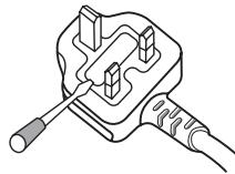
How to replace the fuse: Open the fuse compartment with a screwdriver and replace the fuse.
D3-4-2-1-2-2*A1_EN
WARNING
This equipment is not waterproof. To prevent a fire or shock hazard, do not place any container filled with liquid near this equipment (such as a vase or flower pot) or expose it to dripping, splashing, rain or moisture.
D3-4-2-1-3_A1_En
WARNING
Before plugging in for the first time, read the following section carefully.
The voltage of the available power supply differs according to country or region. Be sure that the power supply voltage of the area where this unit will be used meets the required voltage (e.g., 230 V or 120 V) written on the rear panel.
D3-4-2-1-4*A1En
WARNING
To prevent a fire hazard, do not place any naked flame sources (such as a lighted candle) on the equipment.
D3-4-2-1-7a_A1_En
Operating Environment
Operating environment temperature and humidity: +5^ C to +35^ C ( +41^ F to +95^ F) ; less than 85 % RH (cooling vents not blocked)
Do not install this unit in a poorly ventilated area, or in locations exposed to high humidity or direct sunlight (or strong artificial light)
D3-4-2-1-7c*A1_EN
Symbol for equipment


Symbol examples for batteries


Pb
These symbols on the products, packaging, and/or accompanying documents mean that used electrical and electronic products and batteries should not be mixed with general household waste.
For proper treatment, recovery and recycling of old products and used batteries, please take them to applicable collection points in accordance with your national legislation.
By disposing of these products and batteries correctly, you will help to save valuable resources and prevent any potential negative effects on human health and the environment which could otherwise arise from inappropriate waste handling.
For more information about collection and recycling of old products and batteries, please contact your local municipality, your waste disposal service or the point of sale where you purchased the items.
These symbols are only valid in the European Union.
For countries outside the European Union:
If you wish to discard these items, please contact your local authorities or dealer and ask for the correct method of disposal.
K058a_A1_En
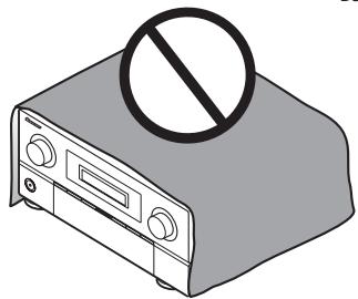
VENTILATION CAUTION
When installing this unit, make sure to leave space around the unit for ventilation to improve heat radiation (at least 20cm at top, 10cm at rear, and 20cm at each side).
WARNING
Slots and openings in the cabinet are provided for ventilation to ensure reliable operation of the product, and to protect it from overheating. To prevent fire hazard, the openings should never be blocked or covered with items (such as newspapers, table-cloths, curtains) or by operating the equipment on thick carpet or a bed.
D3-4-2-1-7b*A1En
If the AC plug of this unit does not match the AC outlet you want to use, the plug must be removed and appropriate one fitted. Replacement and mounting of an AC plug on the power supply cord of this unit should be performed only by qualified service personnel. If connected to an AC outlet, the cut-off plug can cause severe electrical shock. Make sure it is properly disposed of after removal.
The equipment should be disconnected by removing the mains plug from the wall socket when left unused for a long period of time (for example, when on vacation).
D3-4-2-2-1a_A1_En
CAUTION
The OSTANDBY/ON switch on this unit will not completely shut off all power from the AC outlet. Since the power cord serves as the main disconnect device for the unit, you will need to unplug it from the AC outlet to shut down all power. Therefore, make sure the unit has been installed so that the power cord can be easily unplugged from the AC outlet in case of an accident. To avoid fire hazard, the power cord should also be unplugged from the AC outlet when left unused for a long period of time (for example, when on vacation).
D3-4-2-2-2a*A1_EN
This product is for general household purposes. Any failure due to use for other than household purposes (such as long-term use for business purposes in a restaurant or use in a car or ship) and which requires repair will be charged for even during the warranty period.
K041_A1_En
Thank you for buying this pioneer product.
This Quick Start Guide includes instructions for basic connections and operations to allow simple use of the receiver. For detailed descriptions of the receiver, see the "Operating Instructions" provided on the included CD-ROM. The operating instructions can also be downloaded from the Pioneer website (http://www.pioneer.eu).
See below for instructions on handling the CD-ROM.
Operating Environment
This CD-ROM can be used with Microsoft® Windows® XP/Vista/7 and Apple Mac OS X 10.4.
Adobe Reader (Version 4.0 or later) is required to read this CD-ROM.
Precautions For Use
This CD-ROM is for use with a personal computer. It cannot be used with a DVD player or music CD player. Attempting to play this CD-ROM with a DVD player or music CD player can damage speakers or cause impaired hearing due to the large volume.
License
Please agree to the "Terms of Use" indicated below before using this CD-ROM. Do not use if you are unwilling to consent to the terms of its use.
Terms of Use
Copyright to data provided on this CD-ROM belongs to Pioneer Corporation. Unauthorized transfer, duplication, broadcast, public transmission, translation, sales, lending or other such matters that go beyond the scope of "personal use" or "citation" as defined by Copyright Law may be subject to punitive actions. Permission to use this CD-ROM is granted under license by Pioneer Corporation.
General Disclaimer
Pioneer Corporation does not guarantee the operation of this CD-ROM with respect to personal computers using any of the applicable OS. In addition, Pioneer Corporation is not liable for any damages incurred as a result of use of this CD-ROM and is not responsible for any compensation. The names of private corporations, products and other entities described herein are the registered trademarks or trademarks of their respective firms.
* When Using a Mac OS:
Place this CD-ROM in a CD drive and then double-click on the CD-ROM icon to start up the application.
Contents
01 Before you start
Checking what's in the box. 6
Loading the batteries 6
Operating range of remote control unit for infrared (IR) signal transmission 7
Using the RF communications function (SC-LX83 only) 7
Flow for operating the receiver with RF two-way communications (SC-LX83 only) 8
Remote control (In case of SC-LX83). 8
Remote control (In case of SC-LX73). 11
02 Connecting your equipment
Determining the speakers' application 13
Placing the speakers 15
Connecting the speakers 15
Installing your speaker system 16
Selecting the Speaker system. 18
About the audio connection 18
About the video converter. 18
About HDMI 19
Connecting your TV and playback components . 20
Connecting an HDD/DVD recorder, BD recorder and other video sources 23
Connecting a satellite/cable receiver or other set-top box 24
Connecting the multichannel analog inputs. 25
Connecting other audio components 26
Connecting AM/FM antennas. 27
MULTI-ZONE setup. 27
Connecting to the network through
LAN interface 29
Plugging in the receiver 29
03 Basic Setup
Automatically conducting optimum sound tuning (Full Auto MCACC) 30
04 Basic playback
Playing a source. 33
Listening in surround sound. 33
Using Auto surround, ALC, Optimum surround and Stream Direct modes 34
Playing an iPod 35
Playing a USB device 36
Listening to the radio 36
Listening to Internet radio stations (SC-LX73 only) 37
Playback with HOME MEDIA GALLERY inputs (SC-LX83 only) 37
Bluetooth® ADAPTER for Wireless Enjoyment of Music 38
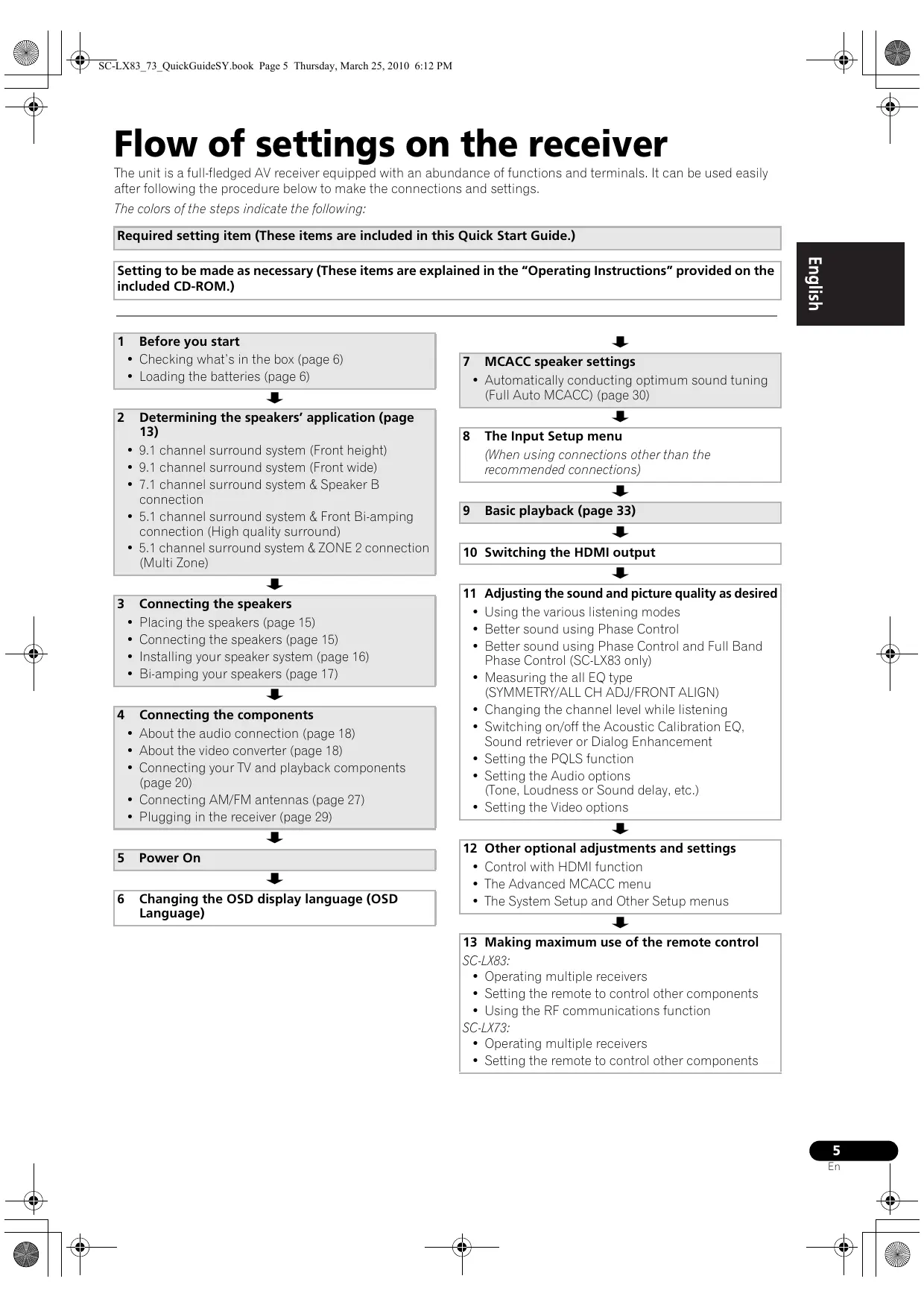
Flow of settings on the receiver
The unit is a full-fledged AV receiver equipped with an abundance of functions and terminals. It can be used easily after following the procedure below to make the connections and settings.
The colors of the steps indicate the following:
Required setting item (These items are included in this Quick Start Guide.)
Setting to be made as necessary (These items are explained in the "Operating Instructions" provided on the included CD-ROM.)
1 Before you start
- Checking what's in the box (page 6)
- Loading the batteries (page 6)

2 Determining the speakers' application (page 13)
9.1 channel surround system (Front height)
9.1 channel surround system (Front wide)
7.1 channel surround system & Speaker B connection
- 5.1 channel surround system & Front Bi-amping connection (High quality surround)
- 5.1 channel surround system & ZONE 2 connection (Multi Zone)

3 Connecting the speakers
- Placing the speakers (page 15)
- Connecting the speakers (page 15)
- Installing your speaker system (page 16)
Bi-amping your speakers (page 17)

4 Connecting the components
- About the audio connection (page 18)
- About the video converter (page 18)
- Connecting your TV and playback components (page 20)
- Connecting AM/FM antennas (page 27)
- Plugging in the receiver (page 29)

5 Power On

6 Changing the OSD display language (OSD Language)

7 MCACC speaker settings
- Automatically conducting optimum sound tuning (Full Auto MCACC) (page 30)

(When using connections other than the recommended connections)

9 Basic playback (page 33)

10 Switching the HDMI output

11 Adjusting the sound and picture quality as desired
- Using the various listening modes
- Better sound using Phase Control
- Better sound using Phase Control and Full Band Phase Control (SC-LX83 only)
- Measuring the all EQ type (SYMMETRY/ALL CH ADJ/FRONT ALIGN)
- Changing the channel level while listening
- Switching on/off the Acoustic Calibration EQ, Sound retriever or Dialog Enhancement
- Setting the PQLS function
- Setting the Audio options (Tone, Loudness or Sound delay, etc.)
- Setting the Video options

12 Other optional adjustments and settings
Control with HDMI function
- The Advanced MCACC menu
- The System Setup and Other Setup menus

13 Making maximum use of the remote control
SC-LX83:
- Operating multiple receivers
- Setting the remote to control other components
- Using the RF communications function
SC-LX73:
- Operating multiple receivers
- Setting the remote to control other components
Chapter 1:
Before you start
Checking what's in the box
Please check that you've received the following supplied accessories:
In case of SC-LX83
- Setup microphone (cable: 5 m)
- Omni-directional remote control (CU-RF100)
RFadapter
- IR blaster cable x2
AA/LR6 dry cell batteries x4
- AM loop antenna
FM wire antenna
- iPod cable
- Bluetooth ADAPTER (AS-BT100)
Power cord
Warranty card
- Operating instructions (CD-ROM)
These quick start guide
In case of SC-LX73
- Setup microphone (cable: 5 m)
- Remote control unit
- AAA size IEC R03 dry cell batteries (to confirm system operation) x2
- AM loop antenna
FM wire antenna
- iPod cable
- Bluetooth ADAPTER (AS-BT100)
Power cord
Warranty card
- Operating instructions (CD-ROM)
These quick start guide
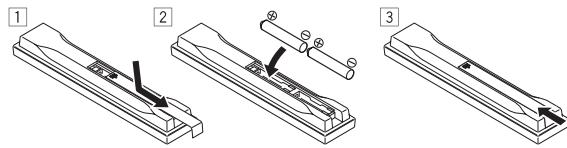
Loading the batteries
In case of SC-LX83
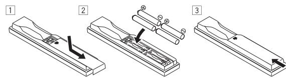
In case of SC-LX73
The batteries included with the unit are to check initial operations; they may not last over a long period.
We recommend using alkaline batteries that have a longer life.
CAUTI
Incorrect use of batteries may result in such hazards as leakage and bursting. Observe the following precautions:
-
Never use new and old batteries together.
-
Insert the plus and minus sides of the batteries properly according to the marks in the battery case.
-
Batteries with the same shape may have different voltages. Do not use different batteries together.
-
When disposing of used batteries, please comply with governmental regulations or environmental public instruction's rules that apply in your country or area.
WARNING
- Do not use or store batteries in direct sunlight or other excessively hot place, such as inside a car or near a heater. This can cause batteries to leak, overheat, explode or catch fire. It can also reduce the life or performance of batteries.
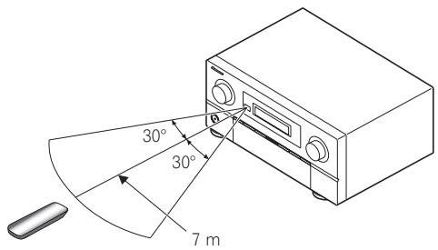
Operating range of remote control unit for infrared (IR) signal transmission
The remote control may not work properly if:
- There are obstacles between the remote control and the receiver's remote sensor.
- Direct sunlight or fluorescent light is shining onto the remote sensor.
- The receiver is located near a device that is emitting infrared rays.
- The receiver is operated simultaneously with another infrared remote control unit.

Tip
- By connecting an RF adapter to the RS-232C and CU-RF100 terminals (SC-LX83) / EXTENSION terminals (SC-LX73), the CU-RF100 omni-directional remote control can be used for RF two-way communications with the receiver. For details, see Using the RF communications function (SC-LX83 only) below.
Using the RF communications function
(SC-LX83 only)
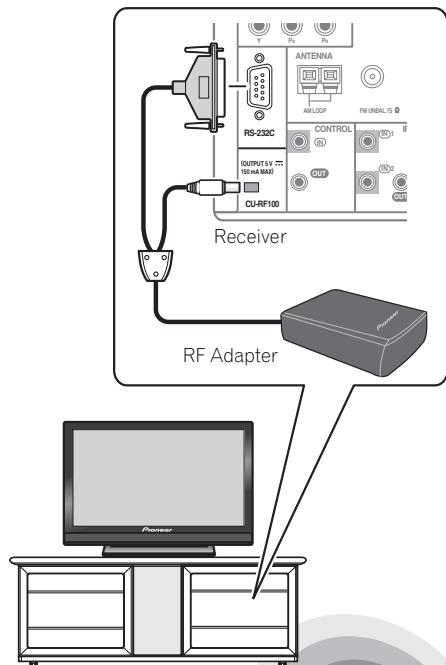
Operation of the receiver or other components placed in a rack is possible
Operation is possible in any direction the remote control is pointed (360^)
With RF two-way communications, the information of the receiver's display can be displayed on the remote control in your hands and the remote control can be operated without worrying about obstacles or the direction in which the remote control is pointing. For details, see Flow for operating the receiver with RF two-way communications (SC-LX83 only) on page 8.
Flow for operating the receiver with RF two-way communications (SC-LX83 only)
This remote control unit is set for operations using infrared signals upon shipment from the factory. To set it for RF operations, take the steps below (See the Operating Instructions in CD-ROM for detail).
1 Connecting the RF adapter to the RS-232C and CU-RF100 terminals.
See Using the RF communications function (SC-LX83 only) on page 7.
2 Setting the 'RF Remote Setup' to 'ON' with the receiver.
1 Switch on the receiver.
2 Push gently on the lower third portion of the receiver's front panel, then press HOME MENU.
3 Use ↑/↓ to select System Setup, then press ENTER.
4 Use ↑/↓ to select Other Setup, then press ENTER.
5 Use ↑/↓ to select RF Remote Setup, then press ENTER.
6 Use / to select ON, then press HOME MENU.
3 Pairing the RF adapter and remote control.
1 Press the SETTING button on the front of the RF adapter.
RF adapter's LED blinks red.
2 While pressing MULTI OPERATION, press VIDEO PARAMETER on the remote control.
The remote display shows PAIRING.
3 Press ENTER on the remote control.
When pairing is successful, SUCCESS is displayed and pairing is completed. RF adapter's LED lights green.
4 Setting 'RECEIVER MAIN' to 'RF MODE' for the remote control unit's 'IR/RF SELECT' setting.
1 While pressing MULTI OPERATION, press HOME MENU.
The remote display shows SETUP MENU
2 Use ↑/↓ to select IR/RF SELECT, then press ENTER.
3 Use ↑/↓ to select RECEIVER MAIN, then press ENTER.
4 Use / to select RF MODE, then press ENTER.
5 Press and hold MULTI OPERATION for a couple of seconds to exit and store the operation.
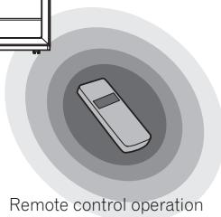
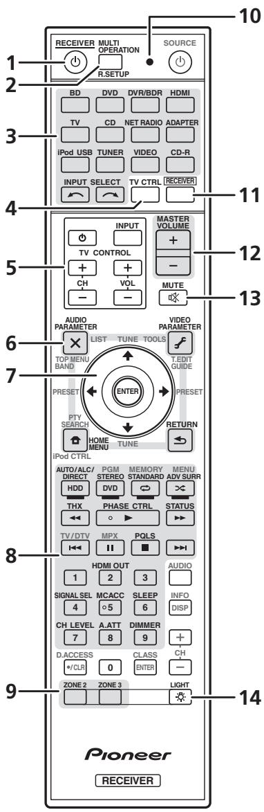
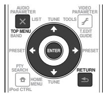
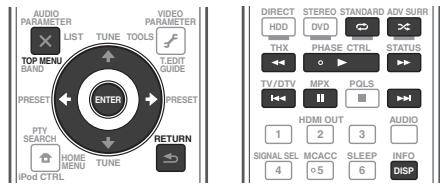
Remote control (In case of SC-LX83)
This section explains how to operate the remote control for the receiver.
The remote has been conveniently color-coded according to component control using the following system:
- White - Receiver control, TV control
- Blue - Other controls (see the Operating Instructions in CD-ROM for detail)
1 MULTI-ZONE operation selector switch
Switch to perform operations in the main zone, ZONE 2 and ZONE 3.
2 RECEIVER
This switches between standby and on for this receiver.
3 MULTI OPERATION
Use this button to perform multi operations.
Press to select control of other components. There is no AUX input on this receiver, so the AUX button cannot be used.
Use to select the input function.
6 Character display
This display shows information when transmitting control signals. The remote screen's display differs when operating the receiver by sending infrared signals from the remote control and when operating it by RF two-way communications. For details, see Remote control display on page 10.
These buttons are dedicated to control the TV assigned to the TV operation selector switch.
Set the remote control operation selector switch to RECEIVER first to access:
AUDIO PARAMETER - Use to access the Audio options.
VIDEO PARAMETER - Use to access the Video options.
HOME MENU - Use to access the Home Menu.
RETURN - Press to confirm and exit the current menu screen.
9 ↑/↓/←/→/ENTER
Use the arrow buttons when setting up your surround sound system and the Audio or Video options.
Set the remote control operation selector switch to RECEIVER first to access:
STATUS - Press to check selected receiver settings.
PHASE CTRL - Press to switch on/off Phase Control or Full Band Phase Control.
CH LEVEL - Press repeatedly to select a channel, then use / to adjust the level.
THX - Press to select a Home THX listening mode.
PQLS - Press to select the PQLS setting.
AUTO/ALC/DIRECT - Switches between Auto Surround (page 34), Auto Level Control, Optimum Surround mode and Stream Direct mode (page 34).
STEREO - Switches between stereo playback and Front Stage Surround Advance modes.
STANDARD - Press for Standard decoding and to switch various modes (Pro Logic, Neo:6, etc.) (page 33).
ADV SURR - Use to switch between the various surround modes (page 34).
SIGNAL SEL - Use to select an input signal.
SLEEP - Use to put the receiver in sleep mode and select the amount of time before sleep.
DIMMER - Dims or brightens the display.
A.ATT - Attenuates (lowers) the level of an analog input signal to prevent distortion.
SBch - With this receiver, SBch cannot be used.
MCACC - Press to switch between MCACC presets.
HDMI OUT - Switch the HDMI output terminal.
11 LIGHT
Press to turn on/off the illumination for the buttons.
12 Remote control operation selector switch Set to RECEIVER to operate the receiver, TV or SOURCE to operate the TV or the source device.
When this switch is set to RECEIVER, the receiver can be controlled (used to select the white commands). Also use this switch to set up surround sound.
13 VOL + / -
Use to set the listening volume.
14 MUTE
Mutes the sound or restores the sound if it has been muted (adjusting the volume also restores the sound).
Note
1 Press and hold in the LIGHT button for 5 seconds to change the illumination mode 1 or 2. When set to LIGHT MODE 2 (default), the illumination only lights when the remote control LIGHT button is pressed. When switched to LIGHT MODE 1, the illumination lights whenever buttons are operated. Setting LIGHT MODE 1 will shorten the service life of the batteries.
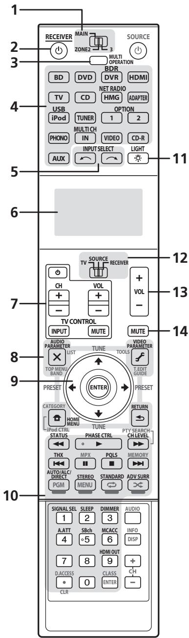
Remote control display1
Remote control display for infrared signal transmission (default)
Remote control display for RF two-way communications²
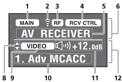
1 Remote control operating zone indicator
This indicates which zone the remote control is currently set to operate. The display indicates the setting of the MULTI-ZONE operation selector switch.
Only when RF two-way communications:
The box display here indicates the communication status between this remote control unit and the receiver.
MAIN (White box with black letters): Two-way communications are established and the receiver's power is on.
MAIN (Gray box with black letters): Two-way communications are established and the receiver's power is off.
MAIN (White letters only): Two-way communications are not working well. In this case, the area indicating the receiver's status (12) is not displayed.
2 Remote control code sending indicator
This appears when signals are sent from the remote control.
3 Remote control code sending mode indicator
This indicates whether remote control codes are being sent by infrared (IR) signal or RF communications.
4 Remote control operation indicator
This indicates which operation mode the remote control is currently set to. The display indicates the setting of the remote control operation selector switch.
This indicates what input function can currently be operated with the remote control. Also, when a button is pressed and its operation code is sent, the name of that code is displayed.
6 Area indicating the remote control's status
7 Nothing displayed
Nothing is displayed here when the remote control code sending mode is set to IR.
Light when there are more selectable items when making the various settings.
This indicates the input function currently selected for the receiver's zone.
10 Receiver display
The same information as on the receiver's display is displayed here.
11 Master volume display
This indicates the volume of the receiver's main zone using, as an icon and in decibels (dB). When the sound is muted, the icon is displayed.
12 Area indicating the receiver's status
Note
1 The display lights when a remote control operation is performed, then turns off after 20 seconds if no other operation is performed. When in the Remote Setup mode, the setup is canceled and the display turns off if no operation is performed for 1 minute.
2 This is displayed when an RF adapter is connected to the receiver and paired with the remote control. For details, see Using the RF communications function on the Operating Instructions in CD-ROM.
- Depending on the communications environment, two-way communications may not work well and the remote control display may not reflect the receiver's status.
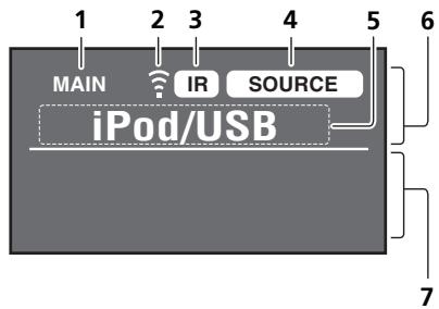
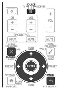
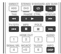
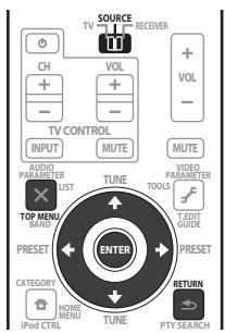
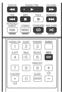
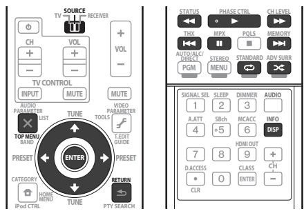
Remote control (In case of SC-LX73)
This section explains how to operate the remote control for the receiver.
The remote has been conveniently color-coded according to component control using the following system:
- White - Receiver control, TV control
- Blue - Other controls (see the Operating Instructions in CD-ROM for detail)
1 念 RECEIVER
This switches between standby and on for this receiver.
2 MULTI OPERATION - Use to perform multi operations.
R.SETUP - Use to input the preset code when making remote control settings and to set the remote control mode.
Press to select control of other components.
Use INPUT SELECT to select the input function.
4 TV CTRL
Set the preset code of your TV's manufacturer when controlling the TV.
These buttons are dedicated to control the TV assigned to the TV CTRL button.
Press RECEIVER first to access:
AUDIO PARAMETER - Use to access the Audio options.
VIDEO PARAMETER - Use to access the Video options.
HOME MENU - Use to access the Home Menu.
RETURN - Press to confirm and exit the current menu screen.
7 / / / / ENTER
Use the arrow buttons when setting up your surround sound system and the Audio or Video options.
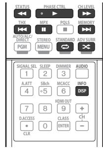
Press RECEIVER first to access:
AUTO/ALC/DIRECT - Switches between Auto Surround (page 34), Auto Level Control mode and Stream Direct mode (page 34).
STEREO - Switches between stereo playback and Front Stage Surround Advance modes.
STANDARD - Press for Standard decoding and to switch various modes (Pro Logic, Neo:6, etc.) (page 33).
ADV SURR - Use to switch between the various surround modes (page 34).
THX - Press to select a Home THX listening mode.
PHASE CTRL - Press to switch on/off Phase Control.
STATUS - Press to check selected receiver settings.
PQLS - Press to select the PQLS setting.
HDMI OUT - Switch the HDMI output terminal.
SIGNAL SEL - Use to select an input signal.
MCACC - Press to switch between MCACC presets.
SLEEP - Use to put the receiver in sleep mode and select the amount of time before sleep.
CH LEVEL - Press repeatedly to select a channel, then use / to adjust the level.
A.ATT - Attenuates (lowers) the level of an analog input signal to prevent distortion.
DIMMER - Dims or brightens the display.
Switch to perform operations in ZONE 2 and ZONE 3.
10 Remote control LED
Lights when a command is sent from the remote control.
11 RECEIVER
Switches the remote to control the receiver (used to select the white commands).
Switch to perform operations in the main zone.
Also use this button to set up surround sound.
12 MASTER VOLUME + / -
Use to set the listening volume.
13 MUTE
Mutes the sound or restores the sound if it has been muted (adjusting the volume also restores the sound).
14
Press to turn on/off the illumination for the buttons. The way the buttons light can be selected from four modes (see the Operating Instructions in CD-ROM for detail).
Chapter 2:
Connecting your equipment
This receiver provides you with many connection possibilities, but it doesn't have to be difficult. This chapter explains the kinds of components you can connect to make up your home theater system.

Important
- Illustration shows the SC-LX83, however connections for the SC-LX73 are the same except where noted.

CAUTION
- Before making or changing the connections, switch off the power and disconnect the power cord from the power outlet. Plugging in should be the final step.
Determining the speakers' application
This unit permits you to build various surround systems, in accordance with the number of speakers you have.
- Be sure to connect speakers to the front left and right channels (L and R).
It is also possible to only connect one of the surround back speakers (SB) or neither.
Choose one from Plans [A] to [E] below.
[A] 9.1 channel surround system (Front height)
*Default setting
- Speaker System setting: Normal(SB/FH)
![PIONEER SC-LX73 - [A] 9.1 channel surround system (Front height) - 1](/content/2019/11/118798/images/34ca1574866746ebace72234b4e8e8220634ef24f0c92cee9b4554b19f32991a.jpg)
A 9.1 ch surround system connects the left and right front speakers (L/R), the center speaker (C), the left and right front height speakers (FHL/FHR), the left and right surround speakers (SL/SR), the left and right surround back speakers (SBL/SBR), and the subwoofer (SW).
This surround system produces a more true-to-life sound from above.
[B] 9.1 channel surround system (Front wide)
- Speaker System setting: Normal(SB/FW)
![PIONEER SC-LX73 - [B] 9.1 channel surround system (Front wide) - 1](/content/2019/11/118798/images/2dd16a6c0e0b3160ed03a6d7933e956d21e9dda365814657f6d35dd012e6e4c6.jpg)
This plan replaces the left and right front height speakers shown in [A] with the left and right front wide speakers (FWL/FWR).
This surround system produces a true-to-life sound over a wider area.
[C] 7.1 channel surround system & Speaker B connection
- Speaker System setting: Speaker B
![PIONEER SC-LX73 - [C] 7.1 channel surround system & Speaker B connection - 1](/content/2019/11/118798/images/db922ff0a38bded73ac03aabeb298f48e265571a31f73495c451a6352d13e613.jpg)
With these connections you can simultaneously enjoy 5.1-channel surround sound in the main zone with stereo playback of the same sound on the B speakers. The same connections also allow for 7.1-channel surround sound in the main zone when not using the B speakers.
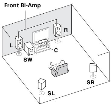
[D] 5.1 channel surround system & Front Bi-amping connection (High quality surround)
- Speaker System setting: Front Bi-Amp
Bi-amping connection of the front speakers for high sound quality with 5.1-channel surround sound.
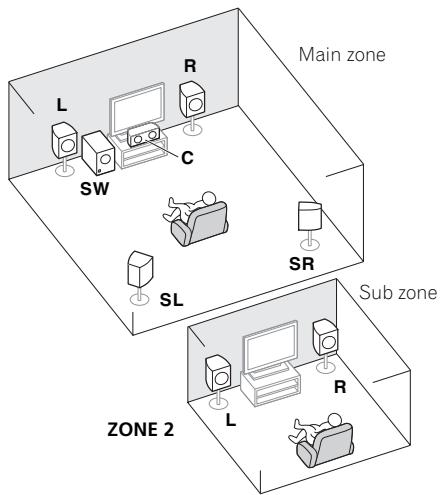
[E] 5.1 channel surround system & ZONE 2 connection (Multi Zone)
- Speaker System setting: ZONE 2
With these connections you can simultaneously enjoy 5.1-channel surround sound in the main zone with stereo playback on another component in ZONE 2. (The selection of input devices is limited.)

Important
- The Speaker System setting must be made if you use any of the connections shown above other than [A] (see Speaker system setting on Operating Instructions in CD-ROM).
- Sound does not come through simultaneously from the front height, front wide, speaker B and surround back speakers. Output speakers are different depending on the input signal or listening mode.
Other speaker connections
- Your favorite speaker connections can be selected even if you have fewer than 5.1 speakers (except front left/right speakers).
- When not connecting a subwoofer, connect speakers with low frequency reproduction capabilities to the front channel. (The subwoofer's low frequency component is played from the front speakers, so the speakers could be damaged.)
- After connecting, be sure to conduct the Full Auto MCACC (speaker environment setting) procedure. See Automatically conducting optimum sound tuning (Full Auto MCACC) on page 30.
Placing the speakers
Refer to the chart below for placement of the speakers you intend to connect.
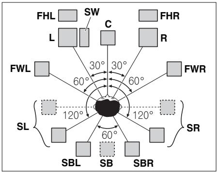
- Place the surround speakers at 120^ from the center. If you, (1) use the surround back speaker, and, (2) don't use the front height speakers / front wide speakers, we recommend placing the surround speaker right beside you.
- If you intend to connect only one surround back speaker, place it directly behind you.
- Place the left and right front height speakers at least one meter directly above the left and right front speakers.
Connecting the speakers
Each speaker connection on the receiver comprises a positive (+) and negative (-) terminal. Make sure to match these up with the terminals on the speakers themselves.

CAUTION
- These speaker terminals carry HAZARDOUS LIVE voltage. To prevent the risk of electric shock when connecting or disconnecting the speaker cables, disconnect the power cord before touching any uninsulated parts.
- Make sure that all the bare speaker wire is twisted together and inserted fully into the speaker terminal. If any of the bare speaker wire touches the back panel it may cause the power to cut off as a safety measure.
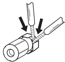
Bare wire connections
1 Twist exposed wire strands together. (fig. A)
2 Loosen terminal and insert exposed wire. (fig. B)
3 Tighten terminal. (fig. C)
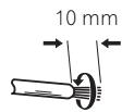
fig. A
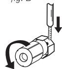
fig. B
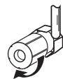
fig. C

Important
- Please refer to the manual that came with your speakers for details on how to connect the other end of the speaker cables to your speakers.
- Use an RCA cable to connect the subwoofer. It is not possible to connect using speaker cables.

CAUTION
- Make sure that all speakers are securely installed. This not only improves sound quality, but also reduces the risk of damage or injury resulting from speakers being knocked over or falling in the event of external shocks such as earthquakes.
Installing your speaker system
At the very least, front left and right speakers only are necessary. Note that your main surround speakers should always be connected as a pair, but you can connect just one surround back speaker if you like (it must be connected to the left surround back terminal).
Standard surround connection
Bi-amping your speakers

Bi-amping is when you connect the high frequency driver and low frequency driver of your speakers to different amplifiers for better crossover performance. Your speakers must be bi-ampable to do this (having separate terminals for high and low) and the sound improvement will depend on the kind of speakers you're using.

CAUTION
- Most speakers with both High and Low terminals have two metal plates that connect the High to the Low terminals. These must be removed when you are bi-amping the speakers or you could severely damage the amplifier. See your speaker manual for more information.
- If your speakers have a removable crossover network, make sure you do not remove it for bi-amping. Doing so may damage your speakers.
Bi-wiring your speakers
Your speakers can also be bi-wired if they support bi-amping.
- With these connections, the Speaker System setting makes no difference.
- To bi-wire a speaker, connect two speaker cords to the speaker terminal on the receiver.

CAUTION
- Don't connect different speakers from the same terminal in this way.
- When bi-wiring as well, heed the cautions for bi-amping shown at the left.
Selecting the Speaker system
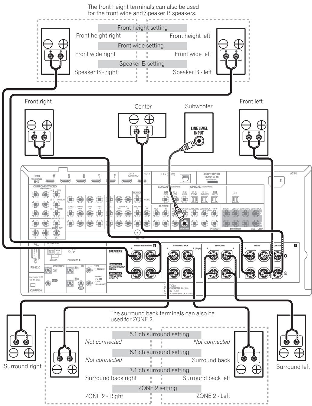
The front height terminals can be used for front wide and Speaker B connections, in addition to for the front height speakers. Also, the surround back terminals can be used for bi-amping and ZONE 2 connections, in addition to for the surround back speakers. Make this setting according to the application.
Front height setup
*Default setting
1 Connect a pair of speakers to the front height speaker terminals.
See Standard surround connection on page 16.
See Speaker system setting on Operating Instructions in CD-ROM to do this.
Front wide setup
1 Connect a pair of speakers to the front height speaker terminals.
See Standard surround connection on page 16.
See Speaker system setting on Operating Instructions in CD-ROM to do this.
Speaker B setup
You can listen to stereo playback in another room.
1 Connect a pair of speakers to the front height speaker terminals.
See Standard surround connection on page 16.
See Speaker system setting on Operating Instructions in CD-ROM to do this.
Bi-Amping setup
Bi-amping connection of the front speakers for high sound quality with 5.1-channel surround sound.
1 Connect bi-amp compatible speakers to the front and surround back speaker terminals.
See Bi-amping your speakers on page 17.
See Speaker system setting on Operating Instructions in CD-ROM to do this.
ZONE 2 setup
With these connections you can simultaneously enjoy 5.1-channel surround sound in the main zone with stereo playback on another component in ZONE 2.
1 Connect a pair of speakers to the surround back speaker terminals.
See Standard surround connection on page 16.
See Speaker system setting on Operating Instructions in CD-ROM to do this.
About the audio connection
| Types of cables and terminals | Transferable audio signals |
| ↑ Audio signal | HDMI | HD audio |
| Digital (Coaxial) | Conventional digital audio |
| Digital (Optical) |
| RCA (Analog)
(White/Red) | Conventional analog audio |
- With an HDMI cable, video and audio signals can be transferred in high quality over a single cable.
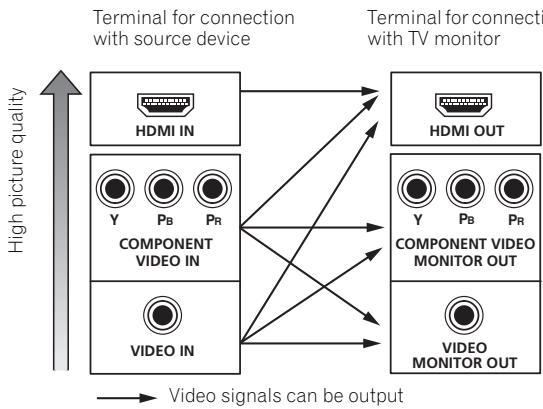
About the video converter
The video converter ensures that all video sources are output through all of the MONITOR VIDEO OUT jacks. The only exception is HDMI: since this resolution cannot be downsampled, you must connect your monitor/TV to the receiver's HDMI video outputs when connecting this video source.
Note
-
If the video signal does not appear on your TV, try adjusting the resolution settings on your component or display. Note that some components (such as video game units) have resolutions that may not be converted. In this case, try switching Digital Video Conversion (in Setting the Video options on Operating Instructions in CD-ROM) OFF.
-
The signal input resolutions that can be converted from the component video input for the HDMI output are 480i/576i, 480p/576p, 720p and 1080i. 1080p signals cannot be converted.
-
Only signals with an input resolution of 480i/576i can be converted from the component video input for the composite MONITOR OUT terminals.
If several video components are assigned to the same input function (see The Input Setup menu on Operating Instructions in CD-ROM), the converter gives priority to HDMI, component, then composite (in that order).
- For optimal video performance, THX recommends switching Digital Video Conversion (in Setting the Video options on Operating Instructions in CD-ROM) OFF.
This product incorporates copyright protection technology that is protected by U.S. patents and other intellectual property rights. Use of this copyright protection technology must be authorized by Rovi Corporation, and is intended for home and other limited viewing uses only unless otherwise authorized by Rovi Corporation. Reverse engineering or disassembly is prohibited.
About HDMI
The HDMI connection transfers uncompressed digital video, as well as almost every kind of digital audio. This receiver incorporates High-Definition Multimedia Interface (HDMI®) technology.
This receiver supports the functions described below through HDMI connections.2
- Digital transfer of uncompressed video (contents protected by HDCP (1080p/24, 1080p/60, etc.))
3D signal transfer
- Deep Color signal transfer3
x.v.Color signal transfer
Audio Return Channel3
- Input of multi-channel linear PCM digital audio signals (192 kHz or less) for up to 8 channels
- Input of the following digital audio formats:4
- Dolby Digital, Dolby Digital Plus, DTS, High bitrate audio (Dolby TrueHD, DTS-HD Master Audio, DTS-HD High Resolution Audio), DVD-Audio, CD, SACD (DSD signal), Video CD, Super VCD
- Synchronized operation with components using the Control with HDMI function (see Control with HDMI function on Operating Instructions in CD-ROM).
HDMI, the HDMI logo and High-Definition Multimedia Interface are trademarks or registered trademarks of HDMI Licensing, LLC in the United States and other countries.
"x.v.Color" and x.v.Color logo are trademarks of Sony Corporation.
Note
1 An HDMI connection can only be made with DVI-equipped components compatible with both DVI and High Bandwidth Digital Content Protection (HDCP). If you choose to connect to a DVI connector, you will need a separate adaptor (DVI HDMI) to do so. A DVI connection, however, does not support audio signals. Consult your local audio dealer for more information.
- If you connect a component that is not compatible with HDCP, an HDCP ERROR message is displayed on the front panel display. Some components that are compatible with HDCP still cause this message to be displayed, but so long as there is no problem with displaying video this is not a malfunction.
- Depending on the component you have connected, using a DVI connection may result in unreliable signal transfers.
This receiver supports SACD, Dolby Digital Plus, Dolby TrueHD and DTS-HD Master Audio. To take advantage of these formats, however, make sure that the component connected to this receiver also supports the corresponding format.
2 - Use a High Speed HDMI® cable. If an HDMI cable other than a High Speed HDMI® cable is used, it may not work properly.
- When an HDMI cable with a built-in equalizer is connected, it may not operate properly.
3 Signal transfer is only possible when connected to a compatible component.
4 - HDMI format digital audio transmissions require a longer time to be recognized. Due to this, interruption in the audio may occur when switching between audio formats or beginning playback.
- Turning on/off the device connected to this unit's HDMI OUT terminal during playback, or disconnecting/connecting the HDMI cable during playback, may cause noise or interrupted audio.
Connecting your TV and playback components
Connecting using HDMI
If you have an HDMI or DVI (with HDCP) equipped component (Blu-ray disc player (BD), etc.), you can connect it to this receiver using a commercially available HDMI cable.
If the TV and playback components support the Control with HDMI feature, the convenient Control with HDMI functions can be used (see Control with HDMI function on Operating Instructions in CD-ROM).
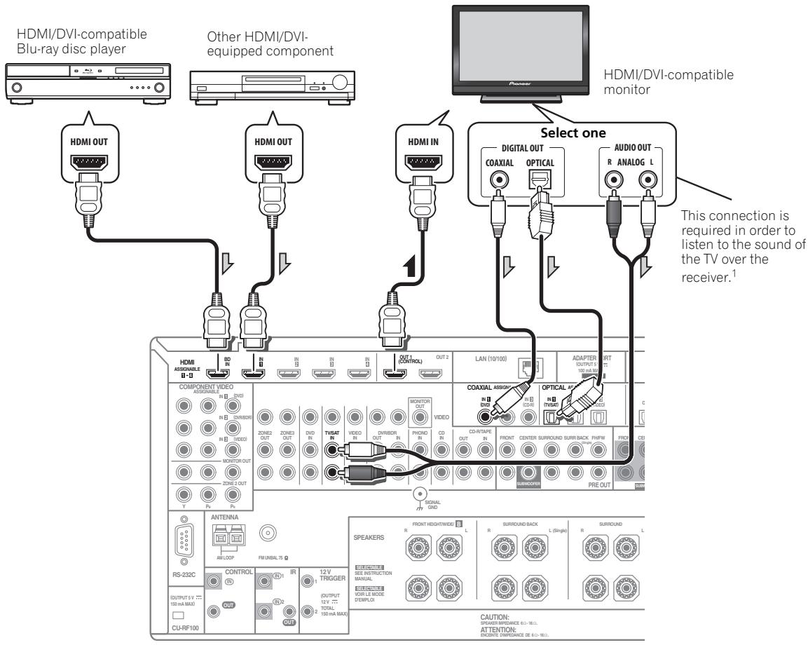
- When connecting to an HDMI/DVI-compatible monitor using the HDMI OUT 2 terminal, switch the HDMI output setting to HDMI OUT 2 or HDMI OUT ALL. See Switching the HDMI output on Operating Instructions in CD-ROM.
-
For input components, connections other than HDMI connections are also possible (see Connecting your DVD player with no HDMI output on page 21).
-
If you want to listen to the sound of the TV over the receiver, connect the receiver and TV with audio cables.

Note
1 When the TV and receiver are connected by HDMI connections, if the TV supports the HDMI Audio Return Channel function, the sound of the TV is input to the receiver via the HDMI terminal, so there is no need to connect an audio cable. In this case, set TV Audio at HDMI Setup via HDMI (see HDMI Setup on Operating Instructions in CD-ROM).
Connecting your DVD player with no HDMI output
This diagram shows connections of a TV (with HDMI input) and DVD player (or other playback component with no HDMI output) to the receiver.
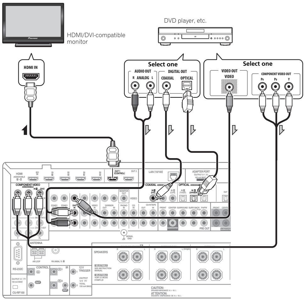
- If you want to listen to the sound of the TV over the receiver, connect the receiver and TV with audio cables (page 20).1
- If you use an optical digital audio cable, you'll need to tell the receiver which digital input you connected the player to (see The Input Setup menu on Operating Instructions in CD-ROM).
Note
1 When the TV and receiver are connected by HDMI connections, if the TV supports the HDMI Audio Return Channel function, the sound of the TV is input to the receiver via the HDMI terminal, so there is no need to connect an audio cable. In this case, set TV Audio at HDMI Setup to via HDMI (see HDMI Setup on Operating Instructions in CD-ROM).
This diagram shows connections of a TV (with no HDMI input) and DVD player (or other playback component) to the receiver.
- With these connections, the picture is not output to the TV even if the DVD player is connected with an HDMI cable. Connect the DVD player's video signals using a composite or component cord.
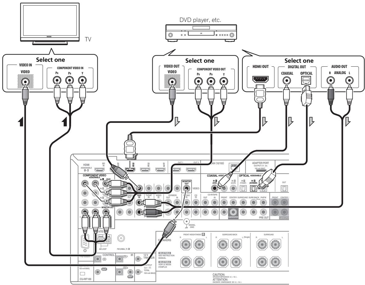
- Connect using an HDMI cable to listen to HD audio on the receiver. Do not use an HDMI cable to input video signals.
Depending on the video component, it may not be possible to output signals connected by HDMI and other methods simultaneously, and it may be necessary to make output settings. Please refer to the operating instructions supplied with your component for more information.
- If you want to listen to the sound of the TV over the receiver, connect the receiver and TV with audio cables (page 20).
- If you use an optical digital audio cable, you'll need to tell the receiver which digital input you connected the player to (see The Input Setup menu on Operating Instructions in CD-ROM).
Connecting an HDD/DVD recorder, BD recorder and other video sources
This receiver has two sets of audio/video inputs and outputs suitable for connecting analog or digital video devices, including HDD/DVD recorders and BD recorders.
When you set up the receiver you'll need to tell the receiver which input you connected the recorder to (see also The Input Setup menu on Operating Instructions in CD-ROM).
HDD/DVD recorder, BD recorder, etc.
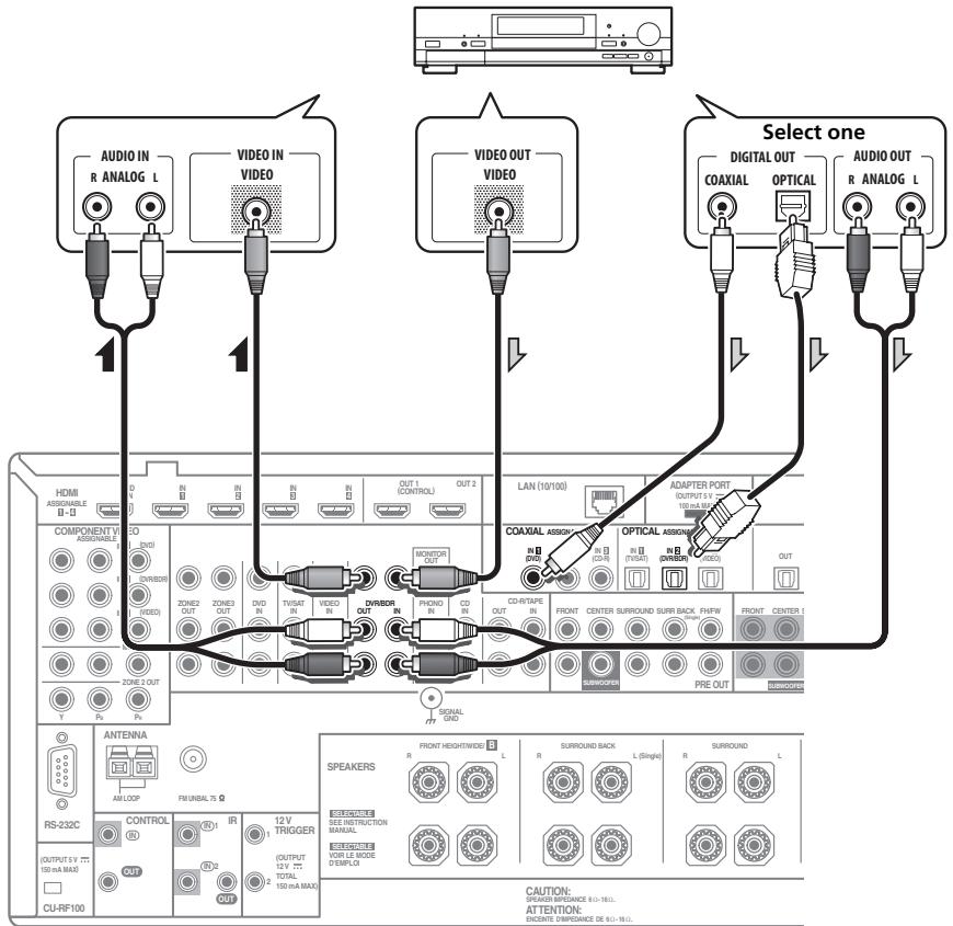
- In order to record, you must connect the analog audio cables (the digital connection is for playback only).
- If your HDD/DVD recorder, BD recorder, etc., is equipped with an HDMI output terminal, we recommend connecting it to the receiver's HDMI IN terminal. When doing so, also connect the receiver and TV by HDMI (see Connecting using HDMI on page 20).
Connecting a satellite/cable receiver or other set-top box
Satellite and cable receivers, and terrestrial digital TV tuners are all examples of so-called 'set-top boxes'.
When you set up the receiver you'll need to tell the receiver which input you connected the set-top box to (see The Input Setup menu on Operating Instructions in CD-ROM).
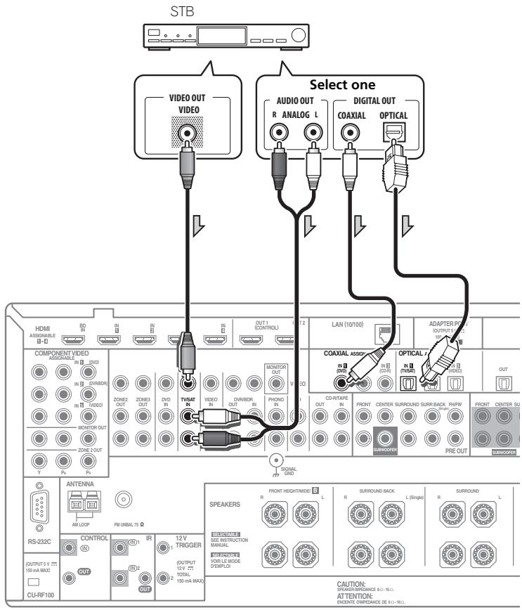
- If your set-top box is equipped with an HDMI output terminal, we recommend connecting it to the receiver's HDMI IN terminal. When doing so, also connect the receiver and TV by HDMI (see Connecting using HDMI on page 20).
For DVD Audio and SACD playback, your DVD player may have 5.1, 6.1 or 7.1 channel analog outputs (depending on whether your player supports surround back channels). Make sure that the player is set to output multichannel analog audio.
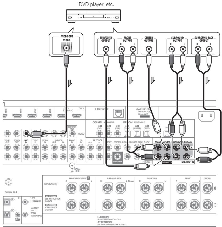
- If there is a single surround back output, connect it to the SURROUND BACK L jack on this receiver.
- To use a 5.1-channel speaker set, use the surround speakers for the surround channel, not the surround back channel.
- The audio signal input to MULTICH IN cannot be downmixed.
Connecting other audio components
This receiver has both digital and analog inputs, allowing you to connect audio components for playback.
When you set up the receiver you'll need to tell the receiver which input you connected the component to (see also The Input Setup menu on Operating Instructions in CD-ROM).
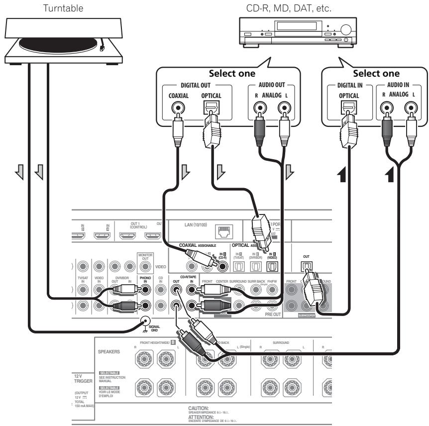
- If you're connecting a recorder, connect the analog audio outputs to the analog audio inputs on the recorder.
- You can't hear HDMI audio through this receiver's digital out jack.
Turntables only:
- If your turntable has a grounding wire, secure it to the ground terminal on this receiver.
- If your turntable has line-level outputs (i.e., it has a built-in phono pre-amp), connect it to the CD inputs instead.
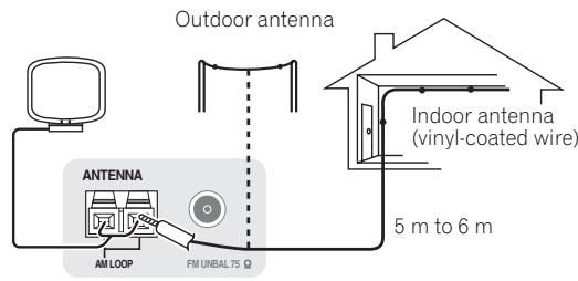
Connecting AM/FM antennas
Connect the AM loop antenna and the FM wire antenna as shown below. To improve reception and sound quality, connect external antennas (see Connecting external antennas below).
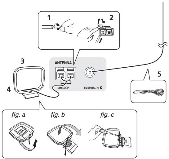
1 Pull off the protective shields of both AM antenna wires.
2 Push open the tabs, then insert one wire fully into each terminal, then release the tabs to secure the AM antenna wires.
3 Fix the AM loop antenna to the attached stand.
To fix the stand to the antenna, bend in the direction indicated by the arrow (fig. a) then clip the loop onto the stand (fig. b).
- If you plan to mount the AM antenna to a wall or other surface, secure the stand with screws (fig. c) before clipping the loop to the stand. Make sure the reception is clear.
4 Place the AM antenna on a flat surface and in a direction giving the best reception.
5 Connect the FM wire antenna into the FM antenna socket.
For best results, extend the FM antenna fully and fix to a wall or door frame. Don't drape loosely or leave coiled up.
Connecting external antennas
To improve FM reception, connect an external FM antenna to FM UNBAL 75Ω.
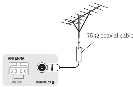
To improve AM reception, connect a 5 m to 6 m length of vinyl-coated wire to the AM LOOP terminals without disconnecting the supplied AM loop antenna.
For the best possible reception, suspend horizontally outdoors.
MULTI-ZONE setup
This receiver can power up to three independent systems in separate rooms after you have made the proper MULTI-ZONE connections.
Different sources can be playing in three zones at the same time or, depending on your needs, the same source can also be used. The main and sub zones have independent power (the main zone power can be off while one (or both) of the sub zones is on) and the sub zones can be controlled by the remote or front panel controls.
Making MULTI-ZONE connections
It is possible to make these connections if you have a separate TV and speakers for your primary (ZONE 2) sub zone, and a separate TV and a separate amplifier (and speakers) for your secondary (ZONE 3) sub zone. You will also need a separate amplifier if you are not using the MULTI-ZONE setup using speaker terminals (ZONE 2) below for your primary sub zone. There are two primary sub zone setups possible with this system. Choose whichever works best for you.
MULTI-ZONE listening options
The following table shows the signals that can be output to ZONE 2 and ZONE 3^1 :
| Sub Zone | Input functions available |
| ZONE 2 | DVD, TV/SAT, DVR/BDR, VIDEO, HOME MEDIA GALLERY (SC-LX83 only), INTERNET RADIO (SC-LX73 only), iPod/USB, CD, CD-R/TAPE, TUNER, ADAPTER PORT (Outputs analog audio, composite video and component video (SC-LX83 only).) |
| ZONE 3 | Same as ZONE 2 above. (Outputs analog audio and composite video.) |
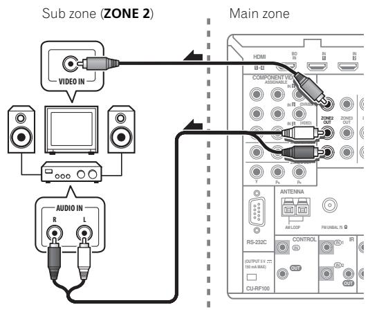
Basic MULTI-ZONE setup (ZONE 2)
- Connect a separate amplifier to the AUDIO ZONE 2 OUT jacks and a TV monitor to the VIDEO ZONE 2 OUT² jack, both on this receiver.
You should have a pair of speakers attached to the sub zone amplifier as shown in the following illustration.
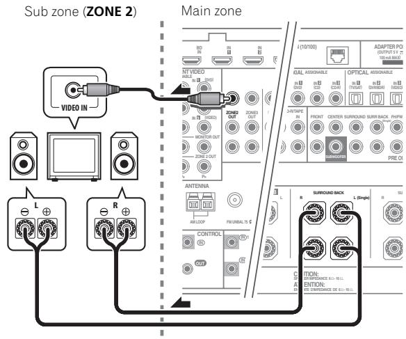
MULTI-ZONE setup using speaker terminals (ZONE 2)
You must select ZONE 2 in Speaker system setting on page 111 to use this setup.
- Connect a TV monitor to the VIDEO ZONE 2 OUT jacks on this receiver.²
You should have a pair of speakers attached to the surround back speaker terminals as shown below.
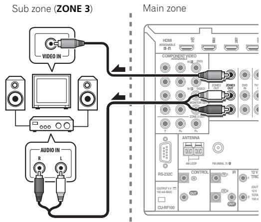
Secondary MULTI-ZONE setup (ZONE 3)
- Connect a separate amplifier to the AUDIO ZONE 3 OUT jacks and a TV monitor to the VIDEO ZONE 3 OUT jack, both on this receiver.
You should have a pair of speakers attached to the sub zone amplifier as shown in the following illustration.
Note
1 For the INTERNET RADIO (SC-LX73 only), HOME MEDIA GALLERY (SC-LX83 only) and iPod/USB inputs, it is not possible use the same input in ZONE 2 and ZONE 3 simultaneously.
2 SC-LX83 only:
- COMPONENT VIDEO ZONE 2 OUT can be used to output clear images.
- The GUI screen is not displayed if only the COMPONENT VIDEO ZONE 2 OUT jack is connected.
- The video convert function does not work for ZONE 2. Connect the composite video and component video to the same types of jacks for the inputs and outputs.
Connecting to the network through LAN interface
By connecting this receiver to the network via the LAN terminal, you can listen to Internet radio stations.1
SC-LX83 only: When connected in this way, you can play audio files stored on the components on the network, including your computer, using HOME MEDIA GALLERY inputs.2
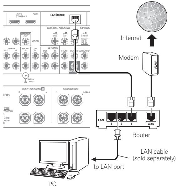
Connect the LAN terminal on this receiver to the LAN terminal on your router (with or without the built-in DHCP server function) with a straight LAN cable (CAT 5 or higher).
Turn on the DHCP server function of your router. In case your router does not have the built-in DHCP server function, it is necessary to set up the network manually. For details, see Network Setup menu on page 113.
LAN terminal specifications
LAN terminal. Ethernet jack
10BASE-T/100BASE-TX
Plugging in the receiver
Only plug in after you have connected all your components to this receiver, including the speakers.
1 Plug the supplied power cord into the AC IN socket on the back of the receiver.
2 Plug the other end into a power outlet.3
CAUTION
- Handle the power cord by the plug part. Do not pull out the plug by tugging the cord, and never touch the power cord when your hands are wet, as this could cause a short circuit or electric shock. Do not place the unit, a piece of furniture, or other object on the power cord or pinch the cord in any other way. Never make a knot in the cord or tie it with other cables. The power cords should be routed so that they are not likely to be stepped on. A damaged power cord can cause a fire or give you an electric shock. Check the power cord once in a while. If you find it damaged, ask your nearest Pioneer authorized independent service company for a replacement.
- Do not use any power cord other than the one supplied with this unit.
- Do not use the supplied power cord for any purpose other than that described below.
- The receiver should be disconnected by removing the mains plug from the wall socket when not in regular use, e.g., when on vacation.
- Make sure the blue STANDBY/ON light has gone out before unplugging.
- If you have connected speakers with a 6 impedance, change the impedance setting before turning on the power.
Note
To listen to Internet radio stations, you must sign a contract with an ISP (Internet Service Provider) beforehand.
2. Photo or video files cannot be played back.
- With Windows Media Player 11 or Windows Media Player 12, you can even play back copyrighted audio files on this receiver.
3 After this receiver is connected to an AC outlet, a 2 second to 10 second HDMI initialization process begins. You cannot carry out any operations during this process. The HDMI indicator in the front panel display blinks during this process, and you can turn on this receiver once it has stopped blinking. When you set the Control with HDMI to OFF, you can skip this process. For details about the Control with HDMI feature, see Control with HDMI function on Operating Instructions in CD-ROM.
Chapter 3: Basic Setup

Important
- The procedure for setting the receiver operation mode differs for the remote controls included with the SC-LX83 and SC-LX73. For the SC-LX83's remote control, set the remote control operation selector switch to RECEIVER. For the SC-LX73's remote control, press the RECEIVER button. When "set the remote control to the receiver operation mode" is indicated in these instructions, use the respective procedure described above.
Automatically conducting optimum sound tuning (Full Auto MCACC)
The Full Auto MCACC Setup measures the acoustic characteristics of your listening area, taking into account ambient noise, speaker connection and speaker size, and tests for both channel delay and channel level. After you have set up the microphone provided with your system, the receiver uses the information from a series of test tones to optimize the speaker settings and equalization for your particular room.
SC-LX83 only: By performing the Full Auto MCACC Setup procedure, the frequency-phase characteristics of the connected speakers are also calibrated.
Once the Full Auto MCACC Setup procedure is completed, the Full Band Phase Control function is automatically turned on.

Important
- Make sure the microphone and speakers are not moved during the Full Auto MCACC Setup.
- Using the Full Auto MCACC Setup will overwrite any existing settings for the MCACC preset you select.
- Before using the Full Auto MCACC Setup, the headphones should be disconnected.

CAUTION
- The test tones used in the Full Auto MCACC Setup are output at high volume.
THX®
- THX is a trademark of THX Ltd., which may be registered in some jurisdictions. All rights reserved.
1 Switch on the receiver and your TV.
Make sure that the TV's video input is set to this receiver.
2 Connect the microphone to the MCACC SETUP MIC jack on the front panel.
- Push down on the lower portion of the front panel door to access the MCACC SETUP MIC jack.
Make sure there are no obstacles between the speakers and the microphone.
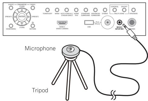
If you have a tripod, use it to place the microphone so that it's about ear level at your normal listening position. If you do not have a tripod, use some other object to install the microphone.1
The Full Auto MCACC display appears once the microphone is connected.2
#
Note
1 Install the microphone on a stable floor. Placing the microphone on any of the following surfaces may make accurate measurement impossible:
- Sofas or other soft surfaces.
- High places such as tabletops and sofa tops.
2 If you leave the GUI screen for over five minutes, the screen saver will appear.
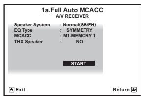
3 Select the parameters you want to set.1
If the speakers are connected using any setup other than Normal(SB/FH), be sure to set Speaker System before the Full Auto MCACC Setup. See Speaker system setting on Operating Instructions in CD-ROM.
- Speaker System ^2 - Shows the current settings. When this is selected and ENTER is pressed, the speaker system selection screen appears. Select the proper speaker system, then press RETURN to return.
- EQ Type - This determines how the frequency balance is adjusted.
- MCACC – The six MCACC presets are used for storing surround sound settings for different listening positions. Simply choose an unused preset for now.
- THX Speaker - Select YES if you are using THX speakers (set all speakers to SMALL), otherwise leave it set to NO.
4 Set the remote control to the receiver operation mode, then select START.
5 Follow the instructions on-screen.
Make sure the microphone is connected, and if you're using a subwoofer, make sure it is switched on and set to a comfortable volume level.
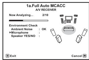
6 Wait for the test tones to finish, then confirm the speaker configuration in the GUI screen.
A progress report is displayed on-screen while the receiver outputs test tones to determine the speakers present in your setup. Try to be as quiet as possible while it's doing this.
If no operations are performed for 10 seconds while the speaker configuration check screen is being displayed, the Full Auto MCACC Setup will resume automatically. In this case, you don't need to select 'OK' and press ENTER in step 7.
- With error messages (such as Too much ambient noise! or Check microphone.), select RETRY after checking for ambient noise (see Problems when using the Auto MCACC Setup on page 32) and verifying the mic connection. If there doesn't seem to be a problem, you can simply select GO NEXT and continue.
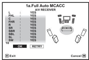
The configuration shown on-screen should reflect the actual speakers you have.
- If you see an ERR message (or the speaker configuration displayed isn't correct), there may be a problem with the speaker connection. If selecting RETRY doesn't work, turn off the power and check the speaker connections. If there doesn't seem to be a problem, you can simply use / to select the speaker and / to change the setting and continue.
-
If Reverse Phase is displayed, the speaker's wiring (+ and -) may be inverted. Check the speaker connections.3
-
If the connections were wrong, turn off the power, disconnect the power cord, then reconnect properly. After this, perform the Full Auto MCACC procedure again.
- If the connections were right, select GO NEXT and continue.
7 Make sure 'OK' is selected, then press ENTER.
A progress report is displayed on-screen while the receiver outputs more test tones to determine the optimum receiver settings.
Again, try to be as quiet as possible while this is happening. It may take 3 to 10 minutes.
Note
- When data measurement is taken, the reverb characteristics data (both before- and after-calibration) that this receiver had been storing will be overwritten. If you want to save the reverb characteristics data before measuring, connect a USB memory device to this receiver and transfer the data.
- When measurement is taken of the reverb characteristics data other than SYMMETRY, the data are not measured after the correction. If you will need to measure after correcting data, take the measurement using the EQ Professional menu in the Manual MCACC setup.
2 If you are planning on bi-amping your front speakers, or setting up a separate speaker system in another room, read through Speaker system setting on Operating Instructions in CD-ROM and make sure to connect your speakers as necessary before continuing to step 4.
3 If the speaker is not pointed to the microphone (listening position) or when using speakers that affect the phase (dipole speakers, reflective speakers, etc.), Reverse Phase may be displayed even if the speakers are properly connected.
8 The Full Auto MCACC Setup procedure is completed and the Home Menu menu reappears automatically.
Be sure to disconnect the microphone from this receiver upon completion of the Full Auto MCACC Setup.1
Problems when using the Auto MCACC Setup
If the room environment is not optimal for the Auto MCACC Setup (too much background noise, echo off the walls, obstacles blocking the speakers from the microphone) the final settings may be incorrect. Check for household appliances (air conditioner, fridge, fan, etc.), that may be affecting the environment and switch them off if necessary. If there are any instructions showing in the front panel display, please follow them.
- Some older TVs may interfere with the operation of the microphone. If this seems to be happening, switch off the TV when doing the Auto MCACC Setup.
Note
-
Depending on the characteristics of your room, sometimes identical speakers with cone sizes of around 12 cm will end up with different size settings. You can correct the setting manually using the Manual speaker setup on Operating Instructions in CD-ROM.
-
The subwoofer distance setting may be farther than the actual distance from the listening position. This setting should be accurate (taking delay and room characteristics into account) and generally does not need to be changed.
-
If Full Auto MCACC Setup measurement results are incorrect due to the interaction of the speakers and viewing environment, we recommend adjusting the settings manually.
Chapter 4: Basic playback

Important
- The procedure for setting the receiver operation mode differs for the remote controls included with the SC-LX83 and SC-LX73. For the SC-LX83's remote control, set the remote control operation selector switch to RECEIVER. For the SC-LX73's remote control, press the RECEIVER button. When "set the remote control to the receiver operation mode" is indicated in these instructions, use the respective procedure described above.
Playing a source
Here are the basic instructions for playing a source (such as a DVD disc) with your home theater system.
1 Switch on your system components and receiver.
Make sure that the TV's video input is set to this receiver.
2 Set the remote control to the receiver operation mode.
3 Select the input function you want to play. You can use the input function buttons on the remote control, INPUT SELECT, or the front panel INPUT SELECTOR dial.
4 Press AUTO/ALC/DIRECT to select 'AUTO SURROUND' and start playback of the source.2
If you're playing a Dolby Digital or DTS surround sound source, you should hear surround sound. If you are playing a stereo source, you will only hear sound from the front left/right speakers in the default listening mode.
5 Use the volume control to adjust the volume level.
Listening in surround sound
Using this receiver, you can listen to any source in surround sound.
Standard surround sound
The following modes provide basic surround sound for stereo and multichannel sources.
While listening to a source, set the remote control to the receiver operation mode, then press STANDARD.
If necessary, press repeatedly to select a listening mode. The listening modes that can be selected depend on the input signals and settings.
With two channel sources, you can select from:
Pro Logic IIx MOVIE
Pro Logic IIx MUSIC
Pro Logic IIx GAME
PROLOGIC -Suitable for old movie
- Pro Logic IIz HEIGHT - Suitable for Front height system
- WIDE SURROUND MOVIE - Suitable for Front wide system
- WIDE SURROUND MUSIC - Suitable for Front wide system
Neo:6 CINEMA
Neo:6 MUSIC
- Neural Surround - Suitable for music sources
With multichannel sources, you can select from:
Pro Logic IIx MOVIE
Pro Logic IIx MUSIC
- Dolby Digital EX-Suitable for movie and music sources
- DTS-ES - Suitable for movie and music sources
- DTS Neo:6 - Suitable for movie and music sources
Pro Logic IIz HEIGHT - See above
WIDE SURROUND MOVIE - See above
WIDE SURROUND MUSIC - See above
- Straight Decode - Plays back without the effects above.
Note
1 If you need to manually switch the input signal type press SIGNAL SEL.
2 You may need to check the digital audio output settings on your DVD player or digital satellite receiver. It should be set to output Dolby Digital, DTS and 88.2kHz / 96kHz PCM (2 channel) audio, and if there is an MPEG audio option, set this to convert the MPEG audio to PCM.
Using the Home THX modes
THX and Home THX are technical standards created by THX Ltd. for cinema and home theater sound. Home THX is designed to make home theater audio sound more like what you hear in a cinema.
- Set the remote control to the receiver operation mode, then press THX to select a listening mode.
The listening modes that can be selected depend on the input signals and settings.
With two channel sources, press THX repeatedly to select from:
THX CINEMA
THX MUSIC
- THX GAMES
Pro Logic IIx MOVIE+THX CINEMA
PRO LOGIC+THX CINEMA
Neo:6 CINEMA+THX CINEMA
Pro Logic IIx MUSIC+THX MUSIC
Neo:6 MUSIC+THX MUSIC
Pro Logic IIx GAME+THX GAMES
Pro Logic IIz HEIGHT+THX CINEMA
Pro Logic IIz HEIGHT+THX MUSIC
Pro Logic IIz HEIGHT+THX GAMES
- THX ULTRA2/SELECT2 GAMES
With multichannel sources, press THX repeatedly to select from:
THX CINEMA
- THX MUSIC
- THX GAMES
- THX Surround EX
Neo:6 CINEMA+THX CINEMA
Pro Logic IIx MOVIE+THX CINEMA
- THX ULTRA2/SELECT2 CINEMA
Pro Logic IIx MUSIC+THX MUSIC
Pro Logic IIz HEIGHT+THX CINEMA
Pro Logic IIz HEIGHT+THX MUSIC
Pro Logic IIz HEIGHT+THX GAMES
- THX ULTRA2/SELECT2 MUSIC
- THX ULTRA2/SELECT2 GAMES
Using the Advanced surround effects
The Advanced surround effects can be used for a variety of additional surround sound effects.
- Set the remote control to the receiver operation mode, then press ADV SURR repeatedly to select a listening mode.
- ACTION
- DRAMA
- SCI-FI - Designed for science fiction with lots of special effects
MONO FILM
- ENT.SHOW - Suitable for musical sources
EXPANDED - Creates an extra wide stereo field
- TV SURROUND
ADVANCED GAME
SPORTS
CLASSICAL
- ROCK/POP
- UNPLUGGED - Suitable for acoustic music sources
- EXT.STEREO - Gives multichannel sound to a stereo source, using all of your speakers
- PHONES SURR - When listening through headphones.
Using Auto surround, ALC, Optimum surround and Stream Direct modes
-
While listening to a source, set the remote control to the receiver operation mode, then press AUTO/ALC/DIRECT to select the mode you want.
-
AUTO SURROUND - The receiver automatically detects what kind of source you're playing and selects multichannel or stereo playback as necessary.
- ALC - The receiver equalizes playback sound levels.
- OPTIMUM SURR (SC-LX83 only) - In the Optimum Surround mode, this receiver automatically optimizes sound balance in each scene based on actually set volume. The sound balancer controls three major theater sound elements dialogue, bass and surround with original algorithm.
- DIRECT - Plays back sound from source with the least modification next to PURE DIRECT. With DIRECT, the only modifications added to PURE DIRECT playback are calibration of the sound field by the MCACC system and the Phase Control effect.
- PURE DIRECT - Plays back unmodified sound from source with only minimal digital treatment. No sound is output from the Speaker B in this mode.
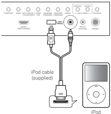
Playing an iPod
This receiver has the iPod/iPhone/USB terminal that will allow you to control playback of audio content from your iPod using the controls of this receiver.
1 Switch the receiver into standby then use the supplied iPod cable to connect your iPod to the iPod/ iPhone/USB terminal on the front panel of this receiver.
2 Switch on the receiver and your TV.
3 Press iPod USB on the remote control to switch the receiver to the iPod/USB.
4 Use / to select 'Music' from the iPod top menu.
5 Use / and ENTER to select the track to be played, then press the PLAY button.
Basic playback controls
SC-LX83:
- Set the remote control operation selector switch to SOURCE, then press iPod USB to switch the remote control to the iPod/USB operation mode.
SC-LX73:
- Press iPod USB to switch the remote control to the iPod/USB operation mode.
Note
This system is compatible with the audio and video of the iPod nano (audio only for the iPod nano 1G), iPod fifth generation (audio only), iPod classic, iPod touch and iPhone. However, some of the functions may be restricted for some models. The system is not compatible with the iPod shuffle.
- Compatibility may vary depending on the software version of your iPod and iPhone. Please be sure to use the latest available software version.
- iPod and iPhone are licensed for reproduction of non-copyrighted materials or materials the user is legally permitted to reproduce.
- Features such as the equalizer cannot be controlled using this receiver, and we recommend switching the equalizer off before connecting.
- Pioneer cannot under any circumstances accept responsibility for any direct or indirect loss arising from any inconvenience or loss of recorded material resulting from the iPod failure.
- When listening to a track on the iPod in the main zone, it is possible to control the sub zone, but not to listen to a different track in the sub zone from the one playing in the main zone.
Playing a USB device
It is possible to play files using the USB interface on the front of this receiver.
1 Switch the receiver into standby then connect your USB device to the USB terminal on the front panel of this receiver.
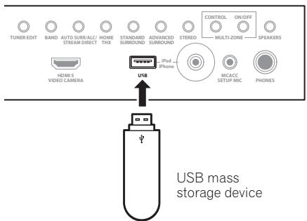
2 Switch on the receiver and your TV.2
3 Press iPod USB on the remote control to switch the receiver to the iPod/USB.
4 Use / to select 'Music' from the USB Top menu.
5 Use / and ENTER to select the track to be played, then press the PLAY button.
Basic playback controls
SC-LX83:
- Set the remote control operation selector switch to SOURCE, then press iPod USB to switch the remote control to the iPod/USB operation mode.
SC-LX73:
- Press iPod USB to switch the remote control to the iPod/USB operation mode.
Listening to the radio
1 SC-LX83 only: Set the remote control operation selector switch to SOURCE.
2 Press TUNER to select the tuner.
3 Use BAND to change the band (FM or AM), if necessary.
4 Tune to a station.
There are three ways to do this:
Automatic tuning - Press and hold TUNE ↑/↓ for about a second. The receiver will start searching for the next station.
Manual tuning - To change the frequency one step at a time, press TUNE ↑/↓.
High speed tuning - Press and hold TUNE ↑/↓ for high speed tuning. Release the button at the frequency you want.
Improving FM sound
If the TUNED or STEREO indicator doesn't light when tuning to an FM station because the signal is weak, press MPX to switch the receiver into mono reception mode.
Using the noise cut mode
The two noise cut modes can be used when receiving AM broadcasts. Press MPX to select the noise cut mode (1 to 2).
Using Neural Surround
This feature uses Neural Surround™ technologies to achieve optimal surround sound from FM radio.
- While listening to FM radio, press AUTO/ALC/DIRECT for Neural Surround.
The Neural Surround mode can be selected also with STANDARD.
Note
- Compatible USB devices include external magnetic hard drives, portable flash memory drives (particularly key drives) and digital audio players (MP3 players) of format FAT16/32.
- Pioneer cannot guarantee compatibility (operation and/or bus power) with all USB mass storage devices and assumes no responsibility for any loss of data that may occur when connected to this receiver.
2 Make sure the receiver is in standby when disconnecting the USB device.
3 The iPod/USB function cannot be selected in the main zone when the Internet radio function is selected in the sub zone. Also, the iPod/USB function cannot be selected in the sub zone when the Internet radio function is selected in the main zone.
Saving station presets
If you often listen to a particular radio station, it's convenient to have the receiver store the frequency for easy recall whenever you want to listen to that station.
1 Tune to a station you want to memorize.
2 Press T.EDIT (TUNER EDIT).
The display shows PRESET MEMORY, then a blinking memory class.
3 Press CLASS to select one of the seven classes, then press PRESET / to select the station preset you want.
4 Press ENTER.
After pressing ENTER, the preset class and number stop blinking and the receiver stores the station.
Listening to station presets
1 SC-LX83 only: Set the remote control operation selector switch to SOURCE.
2 Press TUNER to select the tuner.
3 Press CLASS to select the class in which the station is stored.
4 Press PRESET to select the station preset you want.
Listening to Internet radio stations
(SC-LX73 only)
Internet radio is an audio broadcasting service transmitted via the Internet.

Tip
- This section describes how to listen to Internet radio on the SC-LX73. On the SC-LX83, Internet radio is operated with Home Media Gallery. For details, see Playback with HOME MEDIA GALLERY inputs (SC-LX83 only) below.

Important
- To select stations other than those that are preset, see the CD-ROM Operating Instructions.
1 Connect the LAN terminal on this receiver to the LAN terminal on your router.
See Connecting to the network through LAN interface on page 29.
2 Press NET RADIO to switch to the Internet radio input.
The Internet Radio list screen is displayed.
3 Use / to select the Internet radio station to play back, and then press ENTER.
To return to the list screen, press RETURN.
(SC-LX83 only)
This receiver's Home Media Gallery function allows you to listen to audio files or listen to Internet radio stations on a computer or other component connected to the receiver's LAN terminal.2
1 Connect the LAN terminal on this receiver to the LAN terminal on your router.
See Connecting to the network through LAN interface on page 29.
2 Set the remote control operation selector switch to SOURCE.
3 Press HMG to select Home Media Gallery as the input function.
4 Use / to select the category you want to play back, and then press ENTER.
- Internet Radio - Internet radio
- Neural Music Direct - Internet radio that supports Neural Surround
- Server Name - Server components on the network
- Favorites - Favorite songs currently being registered
- Recently played - Internet Radio listening history (most recent 20 incidents)
5 Use ↑/↓ to select the folder, music files or Internet radio station to play back, and then press ENTER.
6 Repeat step 5 to play back the desired song.
Note
If this function does not operate properly, see the section on Internet radio in the CD-ROM Operating Instructions.
2 - Photo or video files cannot be played back.
- With Windows Media Player 11 or Windows Media Player 12, you can even play back copyrighted audio files on this receiver.
Playing back audio files stored on components on the network
- Set the remote control operation selector switch to SOURCE, then press HMG to switch the remote control to the HOME MEDIA GALLERY operation mode.
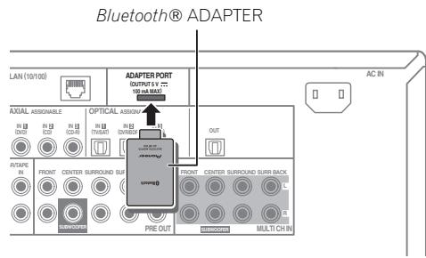
Bluetooth® ADAPTER for Wireless Enjoyment of Music

Important
- Do not move the receiver with the Bluetooth ADAPTER connected. Doing so could cause damage or faulty contact.
- Switch the receiver into standby and connect Bluetooth ADAPTER to the ADAPTER PORT.
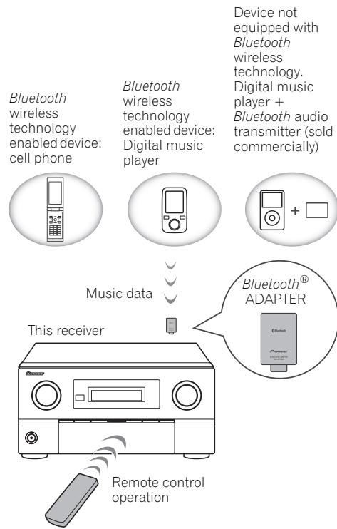
Wireless music play
When the Bluetooth ADAPTER (AS-BT100) is connected to this unit, a product equipped with Bluetooth wireless technology (portable cell phone, digital music player, etc.) can be used to listen to music wirelessly. The AS-BT100 model supports SCMS-T contents protection, so music can also be enjoyed on devices equipped with SCMS-T type Bluetooth wireless technology.
Pairing the Bluetooth ADAPTER and Bluetooth wireless technology device
"Pairing" must be done before you start playback of Bluetooth wireless technology content using the Bluetooth ADAPTER. Make sure to perform pairing the first time you operate the system or any time pairing data is cleared. The pairing step is necessary to register the Bluetooth wireless technology device to enable Bluetooth communications. For more details, see also the operating instructions of your Bluetooth wireless technology device.

Note
If this function does not operate properly, see the section on the Bluetooth ADAPTER in the CD-ROM Operating Instructions.
2 - Pairing is required when you first use the Bluetooth wireless technology device and Bluetooth ADAPTER.
To enable Bluetooth communication, pairing should be done with both your system and Bluetooth wireless technology device.
2 Select 'System Setup', then press ENTER.
3 Select 'Other Setup', then press ENTER.
4 Select 'Pairing Bluetooth Device', then press ENTER.
5 Select the 'Passcode' setting you want.
Select the same passcode as the Bluetooth wireless technology device you wish to connect.
- 0000/1234/8888 - Select the passcode from these options. These are the passcodes that can be used in most cases.
- Others - Select to you use a passcode other than those mentioned above. Use ↑/↓ to select a number and ←/→ to move the cursor.
6 Follow the instructions displayed on the GUI screen to conduct pairing with the Bluetooth wireless technology device.
Switch on the Bluetooth wireless technology device that you want to make pairing, place it near the receiver and set it into the pairing mode.
7 Check to see that the Bluetooth ADAPTER is detected by the Bluetooth wireless technology device.
When Bluetooth wireless technology device is connected:
CONNECTED appears in the receiver display.
When Bluetooth wireless technology device is not connected:
Go back to the passcode setting in step 5. In this case, perform the connection operation from the side of the Bluetooth wireless technology device.
8 From the Bluetooth wireless technology device list, select Bluetooth ADAPTER and enter the Passcode selected in the step 5.2
Listening to music contents of a Bluetooth wireless technology device with your system
1 SC-LX83 only: Set the remote control operation selector switch to SOURCE.
2 Press ADAPTER on the remote control to switch the receiver to ADAPTER PORT input.3
3 From the Bluetooth wireless technology device, perform the operation to connect to the Bluetooth ADAPTER.
4 Start playback of music contents stored on the Bluetooth wireless technology device.
This receiver's remote control buttons can be used for basic playback of files stored on Bluetooth wireless technology devices.
SC-LX83:
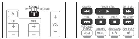
SC-LX73:
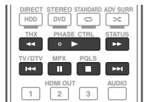
The Bluetooth® word mark and logos are registered trademarks owned by Bluetooth SIG, Inc. and any use of such marks by Pioneer Corporation is under license. Other trademarks and trade names are those of their respective owners.
Published by Pioneer Corporation.
Copyright © 2010 Pioneer Corporation.
All rights reserved.
Note
The system can display alphanumeric characters only. Other characters may not be displayed correctly.
2 Passcode may in some case be referred to as PASSKEY or PIN code.
3 When the Bluetooth ADAPTER is not plugged into the ADAPTER PORT, NO ADAPTER will be displayed if ADAPTER PORT input is selected.
4 • Bluetooth wireless technology device should be compatible with AVRCP profile.
- Depending on the Bluetooth wireless technology device you use, operation may differ from what is shown in the remote control buttons.
It must be necessary that the Bluetooth wireless technology enabled device supports AVRCP profiles.
- Remote control operations cannot be guaranteed for all Bluetooth wireless technology enabled devices.
IMPORTANT

Raccordement surround standard
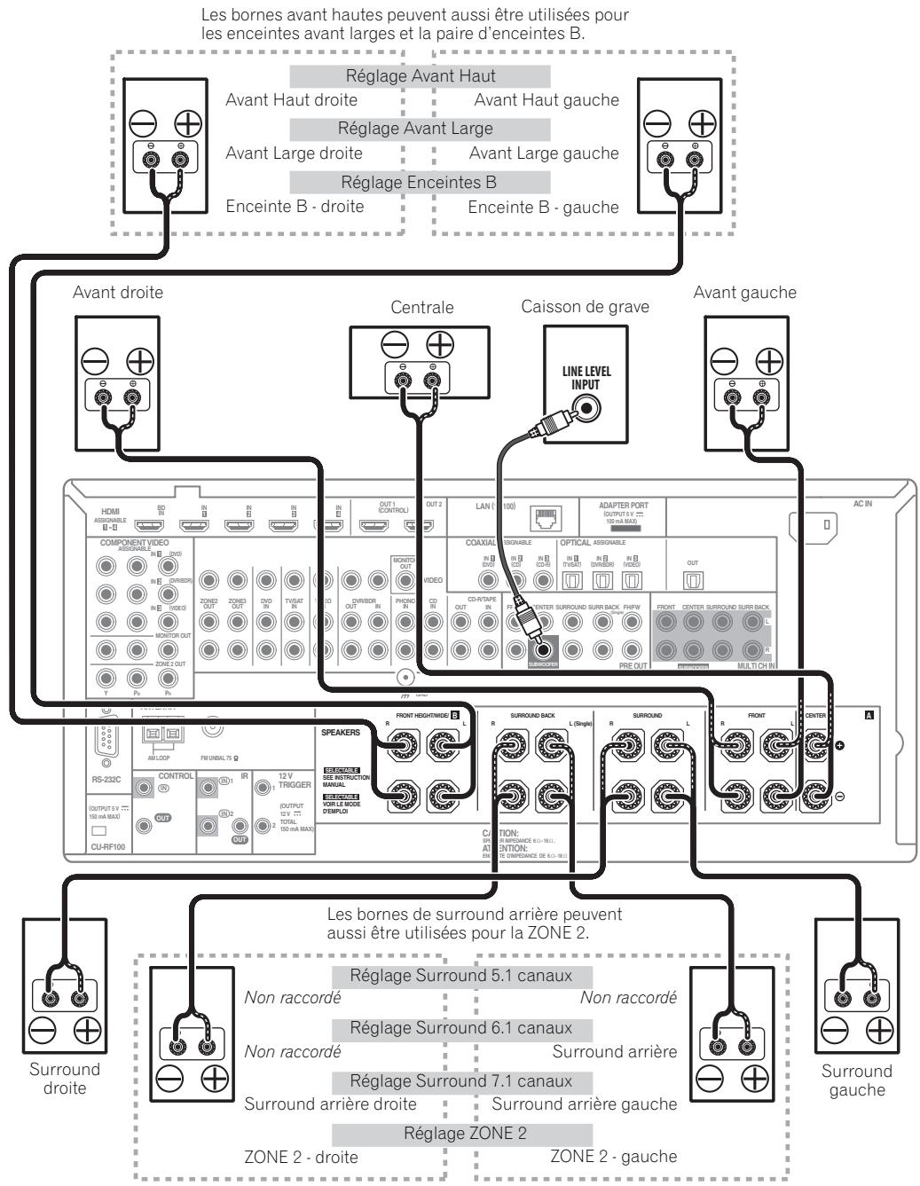
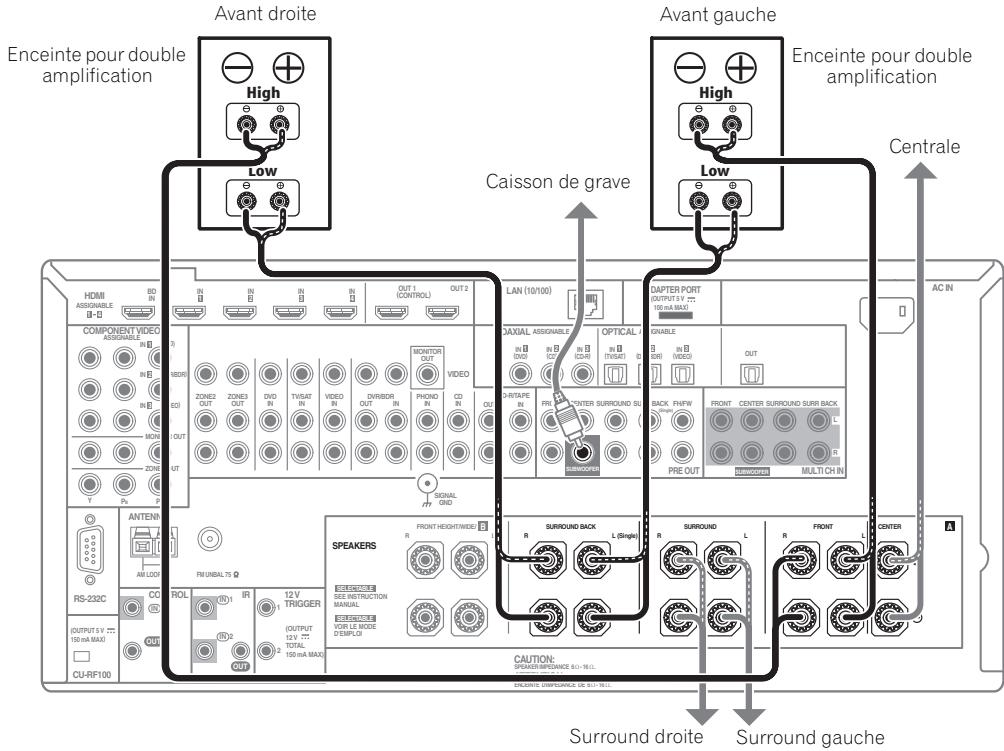
Publication de Pioneer Corporation.
© 2010 Pioneer Corporation.
Manufacturer:
Pioneer Corporation
1-1, Shin-ogura, Saiwai-ku,
Kawasaki-shi, Kanagawa
212-0031, Japan
EU Representative's:
Pioneer Europe NV
Haven 1087, Keetberglaan 1,
9120 Melsele, Belgium
http://www.pioneer.eu
C E
English:
Hereby, Pioneer, declares that this SC-LX83/SC-LX73 is in compliance with the essential requirements and other relevant provisions of Directive 1999/5/EC.
Suomi:
Härmed intygar Pioneer attenna SC-LX83/SC-LX73 stared I
Discover the benefits of registering your product online at http://www.pioneer.co.uk (or http://www.pioneer.eu).
PIONEER ELECTRONICS (USA) INC.
P.O. BOX 1540, Long Beach, California 90801-1540, U.S.A. TEL: (800) 421-1404
PIONEER ELECTRONICS OF CANADA, INC.
300 Allstate Parkway, Markham, Ontario L3R 0P2, Canada TEL: 1-877-283-5901, 905-479-4411
PIONEER EUROPE NV
Haven 1087, Keetberglaan 1, B-9120 Melsele, Belgium TEL: 03/570.05.11
PIONEER ELECTRONICS ASIACENTRE PTE. LTD.
253 Alexandra Road, #04-01, Singapore 159936 TEL: 65-6472-7555
PIONEER ELECTRONICS AUSTRALIA PTY. LTD.
178-184 Boundary Road, Braeside, Victoria 3195, Australia, TEL: (03) 9586-6300
PIONEER ELECTRONICS DE MEXICO S.A. DE C.V.
Blvd. Manuel Avila Camacho 138 10 piso Col.Lomas de Chapultepec, Mexico, D.F. 11000 TEL: 55-9178-4270
K002_B1_En
Published by Pioneer Corporation.
Copyright © 2010 Pioneer Corporation.
All rights reserved.
Publication de Pioneer Corporation.
© 2010 Pioneer Corporation.