QN1B1L2BN0861 - Network cable Panduit - Free user manual and instructions
Find the device manual for free QN1B1L2BN0861 Panduit in PDF.

User questions about QN1B1L2BN0861 Panduit
0 question about this device. Answer the ones you know or ask your own.
Ask a new question about this device
Download the instructions for your Network cable in PDF format for free! Find your manual QN1B1L2BN0861 - Panduit and take your electronic device back in hand. On this page are published all the documents necessary for the use of your device. QN1B1L2BN0861 by Panduit.
USER MANUAL QN1B1L2BN0861 Panduit
Unified Physical Infrastructure


Panduit
PViQ Networked and
Environmental
Monitored POU
PANDUIT®
MN027 Version 2.0
Copyright © 2010 PANDUIT Corp. All rights reserved. No part of this book shall be reproduced, stored in a retrieval system, or transmitted by any means, electronic, mechanical, photocopying, recording or otherwise, without written permission from PANDUIT. No patent liability is assumed with respect to the use of the information contained herein.
Although every precaution has been taken in the preparation of this book, PANDUIT assumes no responsibility for errors or omissions. Neither is any liability assumed for damages resulting from the use of the information contained herein.
Contents
SPECIFICATIONS....5
Overview 5
Environmental 5
Temperature 5
Humidity 5
Elevation 5
Electrical....5
Receptacle Ratings....5
Networking 6
Protocols....6
Ethernet Link Speed 6
Data Formats 6
EMC Verification 6
INSTALLATION....7
Guidelines 7
MOUNTING....8
"L" Bracket 8
Toolless Mounting Hardware 9
NETWORKED MONITORING 11
Network Overview.... 11
Default IP Address 11
Initial Setup 11
WEB INTERFACE 13
Overview 13
Sensors Page 13
Logging Page 15
Display Page 16
Alarms Page 16
Configuration Network Tab 17
Configuration Monitoring Tab 18
Configuration Diagnostics Tab 20
Configuration Event Log Tab 21
Configuration Admin Tab 22
UNIT CONFIGURATION 24
Network Configuration 24
Time and Date 25
E-Mail 25
Status Reports 26
SNMP 27
Accounts and Passwords....27
Telnet 29
Camera Configuration.... 29
Admin Information 29
SSL Certificate Upload....30
ALARMS 31
Alarm Notifications 31
Alarm Types.... 31
Thresholds 31
SENSORS 33
Overview 33
Internal Sensors....33
Remote Sensors 33
Connecting Remote Sensors.... 33
Data Logging and Display 34
ACCESSORIES 35
Remote Display 35
IP-Addressable Network Cameras 35
Alternate Data Formats 35
SERVICE AND TECHNICAL SUPPORT 36
Firmware Version 36
Firmware Updates.... 36
Resetting POU 36
Service 36
Technical Support 36
Specifications
Overview
The PViQ Networked and Environmental POUs are rack level POUs with circuit monitoring via a built-in web server in a self-contained unit. Web pages, including graphs, are generated by the unit to monitor power and environmental conditions within the cabinet. No software other than a web browser is required for operation and several data formats are available. In the PViQ Networked and Environmental POUs, built-in sensors monitor Voltage, Current, instantaneous and cumulative Power, as well as calculated Power Factor. Optional external sensors and network cameras are also available.
Environmental
Temperature
Operating: 10^ C ( 50^ F) min 45^ C ( 113^ F) max
Storage: -25^ ( -13^ ) min 65^ ( 149^ ) max
Humidity
Operating: 5% min 95% max (non-condensing)
Storage: 5% min 95% max (non-condensing)
Elevation
Operating: 0 m (0 ft) min 2000 m (6561 ft) max
Storage: 0 m (0 ft) min 15240 m (50000 ft) max
Electrical
See nameplate for unit ratings.
Receptacle Ratings
NEMA 5-15R or L5-15R 125 Volts, 15 Amp
NEMA 5-20R or L5-20R 125 Volts, 20 Amp
NEMA 6-20R or L6-20R 250 Volts, 20 Amp
IEC-320 C13 125/250 Volt, 15 Amp (North America) or 10 Amp (Global)
IEC-320 C19 125/250 Volt, 20 Amp (North America) or 16 Amp (Global)
Networking
Protocols
HTTP, HTTPS (SSL/TLS), SMTP, POP3, ICMP, DHCP, TCP/IP, NTP, Telnet, Syslog
Ethernet Link Speed
10/100 Mbit; full-duplex
Data Formats
HTML, SNMP, CSV/Plain Text, XML
EMC Verification
This Class A device complies with part 15 of the FCC Rules. Operation is subject to the following two conditions: (1) This device may not cause harmful interference, and (2) this device must accept any interference received, including interference that may cause undesired operation.
This Class A digital apparatus complies with Canadian ICES-003.
Warning: Changes or modifications to this unit not expressly approved by the party responsible for compliance could void the user's authority to operate this equipment.
Installation
Guidelines
- If the POU is installed in a cabinet the ambient temperature of the rack should be no greater than 40^ C.
- Install the POU such that the amount of airflow required for safe operation of equipment is not compromised.
- Mount the POU so that a hazardous condition is not achieved due to uneven mechanical loading.
- Follow nameplate ratings when connecting equipment to the branch circuit. Take into consideration the effect that overloading of the circuits might have on over-current protection and supply wiring.
- The POU relies on the building installation for protection from over-current conditions. A Listed circuit breaker is required within the building installation. The circuit breaker should be sized according to the POU's nameplate ratings and local/national electrical codes.
- Reliable earthing of rack-mount equipment should be maintained. Particular attention should be given to supply connections other than direct connections to the branch circuit. The POU must be connected to an earthed socket-outlet.
- The POU is intended for Restricted Access Locations only and only service personnel should install and access the POU.
- For pluggable equipment, install the POU so that the input plug or appliance coupler may be disconnected for service.
- Sequential power-up of devices powered by the POU is recommended to avoid high inrush current.

Caution: Disconnect all power cords before servicing.
Mounting
"L" Bracket
Affix Power Strip Mounting mounting brackets using #12-24 screws provided into tapped holes in the front or the sides of the post. Power Strip Mounting Brackets can also be mounted to the rear equipment rails.
To center the 66.25" vertical power strips:
- For 7 foot post racks - mount L-Bracket at RU spaces 03 and 43
- For 8 foot 4 post racks, mount L-Bracket at RU spaces 06 and 46 or spaces 07 and 47
- For 6.5 foot 4 post racks, flip bottom bracket 180^ and mount L-bracket at RU spaces 02 and 40
Mount power strip between brackets.

natural_image
Technical line drawing of a wall-mounted device with a bracket and mounting bracket (no text or symbols)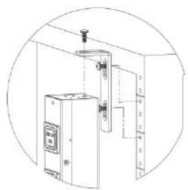
natural_image
Line drawing of an industrial equipment cabinet with piping and control panel (no text or symbols)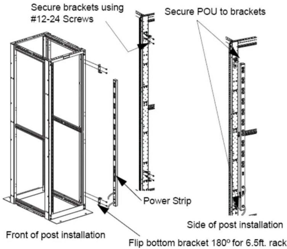
text_image
Secure brackets using #12-24 Screws Secure POU to brackets Power Strip Side of post installation Front of post installation Flip bottom bracket 180° for 6.5ft. rackToolless Mounting Hardware
Use toolless buttons with key-holed slots built into cabinet or with optional key-holed brackets.

text_image
A DETAIL A
text_image
Power Outlet Unit (POU) Button of POU installed
text_image
Panduit Cabinet CS3 1820 20 10 20 10 20 10 20 97 20 10 20 10Networked Monitoring
Network Overview
This product comes preconfigured with a default IP address set. Simply connect to the POU and access the web page with your browser.
Default IP Address
The POU units have a default IP address for initial setup and access to the unit if the assigned address is lost or forgotten. Once an IP address is assigned to a unit, the default IP address is no longer active. To restore the default IP address, press and hold the reset button located below the network connector for 20 seconds. The idle and activity lights on the network connector will both light up when the IP address has been reset. The reset button is accessed through the white, circular hole located below the Ethernet jack.
Note: Pressing the reset button under the network connector will restore the default IP address and will also clear all password settings.
The Configuration page allows you to assign the network properties or use DHCP to connect to your network. Access to the unit requires the IP address to be known, so use of a Static IP or reserved DHCP is recommended. The default address is shown on the front of the unit:
IP Address: 192.168.123.123
Subnet Mask: 255.255.255.0
Gateway: 192.168.123.1
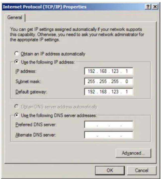
Initial Setup
- Connect POU to your computer using a crossover cable.
- On your computer, go to "Start > Settings > Control Panel > Network and Dial Up Connections."
- Right Click on "Local Area Connection" and select "Properties."
- Select the option to "Use the following IP address" and enter:
IP address: 192.168.123.1
Subnet mask: 255.255.255.0
Default gateway: 192.168.123.1 ^4
- Click "OK" twice.
You can now access the unit using your web browser at the permanent IP address of 192.168.123.1.
text_image
Internet Protocol (TCP/IP) Properties General You can get IP settings assigned automatically if your network supports this capability. Otherwise, you need to ask your network administrator for the appropriate IP settings. Obtain an IP address automatically Use the following IP address: IP address: 192 . 168 . 123 . 1 Subnet mask: 255 . 255 . 255 . 0 Default gateway: 192 . 168 . 123 . 1 Obtain DNS server address automatically Use the following DNS server addresses: Preferred DNS server: . Alternate DNS server: . Advanced... OK CancelTypical Network Card Settings for PC or Laptop to connect to default IP address
Web Interface
Overview
The unit is accessible via a standard, unencrypted HTTP connection as well as an encrypted HTTPS (SSL) connection. The following web pages are available:
Sensors Page
The front page, Sensors, gives both instantaneous and historical views of the unit's data. Real time readings are provided for all power strip and sensor data next to historical graphs.
Optional cameras may be added and their live snapshots are shown on this page. Plug-and-play sensors appear below the internal sensors when attached.
The menu bar allows access to the rest of the PDU's functionality.
PANDUIT®
PVIQ POU 1 Networked
IP Address: 192.168.1.111
Local Time: Thu, 12/09/10 13:30:08
PVIQ POU 1 Networked v3.5.6
All is well: 1 Alarms monitored
| Sensors |
| Alarms |
| Logging |
| Display |
| Config |
| Help |
| PDA/Phone |XML | MIB |
Sensors
| PVIQ POU 1 Networked | ID 018B6A081400004B | |
| kWatt-hours [A] | 1.11 kWh | |
| Volts [A] | 118.20 V_rms | |
| Volts (Peak) [A] | 118.40 V_rms | |
| Amps [A] | 0.02 A_rms | |
| Amps (Peak) [A] | 0.00 A_rms | |
| Real Power [A] | 0.00 Watts | |
| Apparent Power [A] | 2.4 Watts | |
| Power Factor [A] | 100.0 % | |
| kWatt-hours [B] | 1.83 kWh | |
| Volts [B] | 118.70 V_rms | |
| Volts (Peak) [B] | 119.30 V_rms | |
| Amps [B] | 0.02 A_rms | |
| Amps (Peak) [B] | 0.00 A_rms | |
| Real Power [B] | 0.00 Watts | |
| Apparent Power [B] | 2.4 Watts | |
| Power Factor [B] | 100.0 % | |
| kWatt-hours [C] | 0.00 kWh | |
| Volts [C] | 120.60 V_rms | |
| Volts (Peak) [C] | 120.70 V_rms | |
| Amps [C] | 0.02 A_rms | |
| Amps (Peak) [C] | 0.00 A_rms | |
| Real Power [C] | 0.00 Watts | |
| Apparent Power [C] | 2.4 Watts | |
| Power Factor [C] | 100.0 % | |

line
| Time | Value | |---|---| | 7d | 120 | | 6d | 120 | | 5d | 120 | | 4d | 120 | | 3d | 120 | | 2d | 120 | | 1d | 120 | | Cd | 120 |ID 2E00000246986428
Temp Sensor

Temperature (F)
77.22 °F

line
| Time | Value | |------|-------| | 7d | 78.5 | | 6d | 77.2 | | 5d | 77.8 | | 4d | 78.1 | | 3d | 77.5 | | 2d | 76.8 | | 1d | 77.9 | | 0d | 77.3 |Logging Page
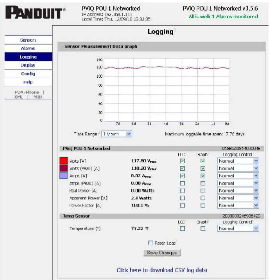
The Logging page allows the user to access the historical data by selecting the desired sensors and time range to be graphed. Selected sensor values are logged into the data file at a rate of one point per minute. Please note that although data is logged once per minute, all sensor data used in the real time display and alarm functions is read at least once every 15 seconds for internal sensors and once every 30 seconds for external sensors. Checked readings are displayed on the optional remote display module. Recorded data is available for download in a comma-separated values (CSV) file.
text_image
PANDUIT® PViQ POU 1 Networked IP Address: 192.168.1.111 Local Time: Thu, 12/09/10 13:33:35 PViQ POU 1 Networked v3.5.6 All is well: 1 Alarms monitored Sensors Alarms Logging Display Config Help PDA/Phone | XML | MIB Logging Sensor Measurement Data Graph Time Range: 1 Month Maximum loggable time span: 7.76 days PViQ POU 1 Networked 018B6/A081400004B LCD Graph Logging Control Volts [A] 117.80 Vrms Normal Volts (Peak) [A] 118.20 Vrms Normal Amps [A] 0.02 Arms Normal Amps (Peak) [A] 0.00 Arms Normal Real Power [A] 0.00 Watts Normal Apparent Power [A] 2.4 Watts Normal Power Factor [A] 100.0 % Temp Sensor 2E00000246986428 Temperature (F) 77.22 °F LCD Graph Logging Control Reset Logs Save Changes Click here to download CSV log dataDisplay Page
The Display page allows the user to assign friendly names to attached sensors as well as change the default temperature unit of measure for external sensors. The display page also allows the user to select between the default and classic web page layouts. The default interface displays a vertical menu bar to the left of the main window, while the classic interface displays a horizontal menu bar.

text_image
PANDUIT® PVIQ POU 1 Networked IP Address: 192.168.1.111 Local Time: Thu, 12/09/10 13:38:25 PVIQ POU 1 Networked v3.5.6 All is well: 1 Alarms monitored Display General Date Format: USA (MW/DC/YY) Temperature Unit: Fahrenheit Interface Type: Default Scroll on LCD: Measurements Save Changes Devices Unique Address Device Type Friendly Name 01885A0814C0004B cb/BCHEC PVIQ POU 1 Networked 2B0000024658542B tempSensor Temp Sensor Remove all unplugged devices Save ChangesAlarms Page
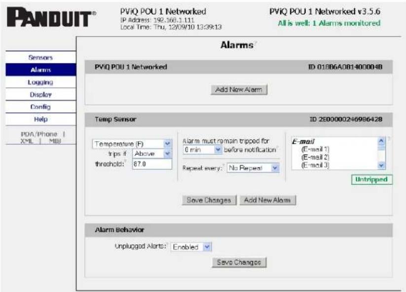
The Alarms page allows the user to establish alarm conditions for each sensor reading. Alarm conditions can be established with either high or low trip thresholds. The alarms are displayed in different sections based on the device the alarm is associated with. Alarm options include a local Buzzer, Email and SNMP Trap.
text_image
PANDUIT® PVIQ POU 1 Networked IP Address: 192.166.1.111 Local Time: Thu, 12/09/10 13:39:13 PVIQ POU 1 Networked v3.5.6 All is well: 1 Alarms monitored Alarms PVIQ POU 1 Networked ID 01806A0814000048 Add New Alarm Temp Sensor ID 2E00000246986428 Temperature (F) trips if Above threshold: 87.0 Alarm must remain tripped for 0 min before notification Repeat every: No Repeat E-mail (E-mail 1) (E-mail 2) (E-mail 3) Untripped Save Changes Add New Alarm Alarm Behavior Unplugged Alerts: Enabled Save ChangesThe Configuration page has five sub-tabs; Network, Monitoring, Diagnostics, Event Log, and Admin. See Unit Configuration (page 24) for details.
Configuration Network Tab
The user can enter and update the network settings on the Network tab of the Configuration page. See Unit Configuration section for details.

text_image
PANDUIT® PVIQ POU 1 Networked IP Address: 192.168.1.111 Local Time: Thu, 12/09/10 13:40:44 PVIQ POU 1 Networked v3.5.6 All is well: 1 Alarms monitored Sensors Alarms Logging Display Config Network Monitoring Diagnostics Event Log Admin Help PDA/Phone | XML | MIB Configuration Network? Current Network Configuration set statically Use DHCP for Network Configuration and DNS Server Addresses Use DHCP for Network Configuration and Static DNS server addresses: Use Static Network Configuration and DNS server addresses: IP Address: 192.168.1.111 Subnet Mask: 255.255.252.0 Gateway: 192.168.0.2 Primary DNS Server: 8.8.8.8 Secondary DNS Server: 8.8.4.4 Save Changes Web Server Protocols: HTTP and HTTPS HTTP Port: 80 HTTPS Port: 443 Telnet Service: Enabled Save ChangesConfiguration Monitoring Tab
The user can enter and update the email alert, SNMP, and camera settings on the Monitoring tab of the Configuration page. See Unit Configuration section for details.

text_image
PANDUIT® PVIQ POU 1 Networked IP Address: 192.168.1.111 Local Time: Thu, 12/09/10 13:43:38 PVIQ POU 1 Networked v3.5.6 All is well: 1 Alarms monitored Sensors Alarms Logging Display Config Network Monitoring Diagnostics Event Log Admin Help PDA/Phone | XML | MIB Configuration E-mail SMTP Server: SMTP Port: 25 "From" E-mail Address: Send alarms to this recipient: Always Business After Hours SMS To E-mail Address 1: ○ ○ ○ □ To E-mail Address 2: ○ ○ ○ □ To E-mail Address 3: ○ ○ ○ □ To E-mail Address 4: ○ ○ ○ □ To E-mail Address 5: ○ ○ ○ □ POP3 Server: POP3 Port: 110 Username: Password: Save Changes Business Hours Start Time: 09:00 End Time 17:00 Sun Mon Tue Wed Thu Fri Sat Week Days: □ ✓ ✓ ✓ ✓ ✓ □ Save ChangesSystem Status E-Mail Reports
Add New Report
SNMP
SNMP Service: Enabled
Read Community: public
Listen port for GET: 161
Trap Community: private
Write Community: private
Trap Type: V2C Notify
Trap IP Address: port 1: 192.168.0.78:162
192.168.0.78
Trap IP Address: port 2:
Save Charges
Initial SNMPV3 data
Unauthenticated User: Initial
Authenticated Manager: manager
Manager Authentication 12345678
Password:
Manager Privacy Password: 12345678
Trap User: Trap
Trap Authentication 12345678
Password:
Trap Privacy Password: 12345678
Save Changes
Reset User/Access NVRAM will occur during the finish page.
Cameras
text_image
Cam 1, IP Address: 0.0.0.0 Model: No camera Cam 2, IP Address: 0.0.0.0 Model: No camera Cam 3, IP Address: 0.0.0.0 Model: No camera Cam 4, IP Address: 0.0.0.0 Model: No cameraSave Changes
Test SNMP Trap and E-Mail
Send Test SNMP Trap
Send TestE-Mail
Configuration Diagnostics Tab
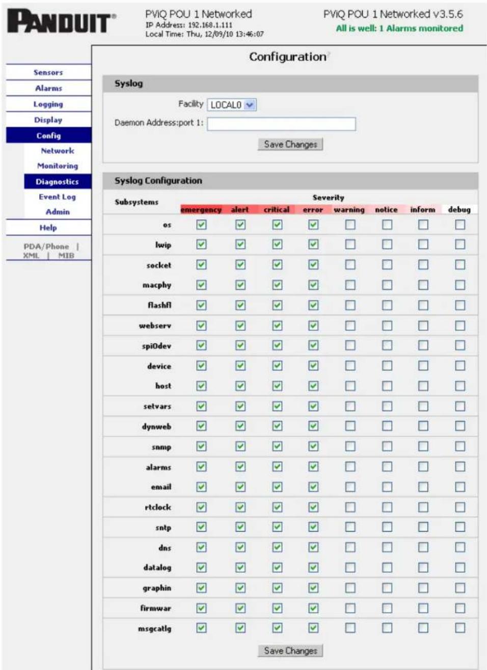
The user can update the Syslog settings on the Diagnostics tab of the Configuration page.
text_image
PANDUIT® PVIQ POU 1 Networked IP Address: 192,168.1.111 Local Time: Thu, 12/09/10 13:46:07 PVIQ POU 1 Networked v3.5.6 All is well: 1 Alarms monitored Sensors Alarms Logging Display Config Network Monitoring Diagnostics Event Log Admin Help PDA/Phone | XML | MIB Configuration® Syslog Facility LOCAL0 Daemon Address: port 1: Save Changes Syslog Configuration Subsystems Severity emergency alert Critical ewor#warning notice inform debug os ✓ ✓ ✓ ✓ □ □ □ □ lwip ✓ ✓ ✓ ✓ □ □ □ □ socket ✓ ✓ ✓ ✓ □ □ □ □ macphy ✓ ✓ ✓ ✓ □ □ □ □ flashfl ✓ ✓ ✓ ✓ □ □ □ □ webserv ✓ ✓ ✓ ✓ □ □ □ □ spiOdev ✓ ✓ ✓ ✓ □ □ □ □ device ✓ ✓ ✓ ✓ □ □ □ □ host ✓ ✓ ✓ ✓ □ □ □ □ setvars ✓ ✓ ✓ ✓ □ □ □ □ dynweb ✓ ✓ ✓ ✓ □ □ □ □ snmp ✓ ✓ ✓ ✓ □ □ □ □ alarms ✓ ✓ ✓ ✓ □ □ □ □ email ✓ ✓ ✓ ✓ □ □ □ □ rtclock ✓ ✓ ✓ ✓ □ □ □ □ sntp ✓ ✓ ✓ ✓ □ □ □ □ dns ✓ ✓ ✓ ✓ □ □ □ □ datalog ✓ ✓ ✓ ✓ □ □ □ □ graphin ✓ ✓ ✓ ✓ □ □ □ □ firmwar Save ChangesConfiguration Event Log Tab
The user can view the Event Log and update the Memory Syslog settings on the Event Log tab of the Configuration page.
text_image
PANDUIT® PVIQ POU 1 Networked IP Address: 192.168.1.111 Local Time: Thu, 12/09/10 13:51:35 PVIQ POU 1 Networked v3.5.6 All is well: 1 Alarms monitored Configuration NVRAM Event Log Click here to view NVM event log Clear NVM event log Memory Syslog 12/9/2010 13:51:34 setvars::vars_from_pairs: path=[/dyn_config_event1] 12/9/2010 13:51:34 setvars::vars_from_pairs: got vars_config_lock, 0 12/9/2010 13:46:06 setvars::vars_from_pairs: path=[/dyn_config_diagno] 12/9/2010 13:46:06 setvars::vars_from_pairs: got vars_config_lock, 0 12/9/2010 13:43:37 setvars::vars_from_pairs: path=[/dyn_config_monito] 12/9/2010 13:43:37 setvars::vars_from_pairs: got vars_config_lock, 0 12/9/2010 13:40:43 setvars::vars_reset_dhcp_status: resetting net_dhc 12/9/2010 13:40:43 setvars::vars_from_pairs: path=[/dyn_config.htm]. 12/9/2010 13:39:13 setvars::vars_from_pairs: path=[/dyn_Alarms.htm]. 12/9/2010 13:39:13 setvars::vars_from_pairs: got vars_config_lock, 0 12/9/2010 13:38:24 setvars::vars_from_pairs: path=[/dyn_display.htm]. 12/9/2010 13:38:24 setvars::vars_from_pairs: got vars_config_lock, 0 12/9/2010 13:33:34 setvars::vars_from_pairs: path=[/dyn_logging.htm]. 12/9/2010 13:33:34 setvars::vars_from_pairs: got vars_config_lock, 0 12/9/2010 13:32:55 setvars::vars_from_pairs: path=[/dyn_sensors.htm]. 12/9/2010 13:32:55 setvars::vars_from_pairs: got vars_config_lock, 0 12/9/2010 13:31:29 setvars::vars_from_pairs: path=[/dyn_sensors.htm]. 12/9/2010 13:31:29 setvars::vars_from_pairs: got vars_config_lock, 0 12/9/2010 13:30:07 setvars::vars_from_pairs: path=[/dyn_sensors.htm]. Memory Syslog Subsystems Severity emergency alert critical error warning notice inform debug os □ □ □ □ □ □ □ □ □ lwip □ □ □ □ □ □ □ □ □ socket □ □ □ □ □ □ □ □ □ macphy □ □ □ □ □ □ □ □ □ flashfl □ □ □ □ □ □ □ □ □ webserv □ □ □ □ □ □ □ □ □ spiOdev □ □ □ □ □ □ □ □ □ device □ □ □ □ □ □ □ □ host □ □ □ □ □ □ □ □ □ setvars ✓ ✓ ✓ ✓ ✓ ✓ ✓ ✓ dynweb □ □ □ □ □ □ □ □Configuration Admin Tab
The user can set the system clock and administrative information on this tab. Additionally the user can set administrator and account passwords. See Unit Configuration section for details.

text_image
PANDUIT® PVIQ POU 1 Networked (P Address: 192.168.1.111 Local Time: Thu, 12/06/10 13:53:48 PVIQ POU 1 Networked v3.5.6 All is well: 1 Alarms monitored Sensors Alarms Logging Display Config Network Monitoring Diagnostics Event Log Admin Help PDA/Phone | XML | MIB Configuration All Parameters Reset ALL to Default Values Refresh DNS Cache PVIQ POU 1 Networked Reset kWh Reset Circuit A Reset Circuit B Reset Circuit C Reset all circuits System Clock, set to GMT Set Clock method: Manual-GMT GMT to local, (-/-)hh:mm =00.00 Make sure you are in GMT time zone Month Day Year Hour Minute Second 12 09 10 13 53 48 (yy) (0-23) (0-59) (0-59) NTP primary server 192.43.244.18 192.43.244.18 NTP secondary server 129.6.15.28 129.6.15.28 Sync to NTP server period (seconds) 1800 Save Changes
text_image
Daylight Saving Time? DST is DISABLED Enable DST: Disabled DST Start: 1st Sun in Jan at 00:00 DST End: 1st Sun in Feb at 00:00 Save Changes Name and Password Configuration NOTE 1st Account currently has a password, leaving old Password blank results in no change to that account. NOTE 2nd Administrator password may be used in the Old Password field of any account. NOTE 3rd setting New Password to blank, Account Name must also be blank. NOTE 4th New Password is not blank. Account Name must not be blank. Administrator Account Name: Old Password New Password New Password Again (again, to confirm) Warning: Record your password. Loss of password may require 48 hours to recover. Control Account Name: Old Password New Password New Password Again (again, to confirm) Warning: Record your password. Loss of password may require 48 hours to recover. View Only Account Name: Old Password New Password New Password Again (again, to confirm) Warning: Record your password. Loss of password may require 48 hours to recover. Save Changes Admin Info Contact Name: Contact Email: (sysContact) Contact Phone: Device Location: (sysLocation) Device Description: (sysName) Save Changes Saved Configuration XML File XML File: Browse_ Upload Local XML File Download Current XML File SSL Certificate and Private Key SSL Certificate and Private Key are INVALID SSL Certificate File: Browse_ SSL Private Key File: Browse_ Upload SSL Files Erase SSL Data Upload System Firmware Firmware package file: Browse_ Upload New Firmware Firmware upload may take a few minutes. Please wait for response from browser.Unit Configuration
Network Configuration
The unit's network configuration is set on the Network tab of the Configuration page. Settings pertaining to the unit's network connection are:
text_image
Network Current Network Configuration set statically Use DHCP for Network Configuration and DNS Server Addresses Use DHCP for Network Configuration and Static DNS server addresses: Use Static Network Configuration and DNS server addresses: IP Address: 192.168.1.111 Subnet Mask: 255.255.252.0 Gateway: 192.168.0.2 Primary DNS Server: 8.8.8.8 Secondary DNS Server: 8.8.4.4 Save Changes
text_image
Web Server Protocols: HTTP and HTTPS HTTP Port: 80 HTTPS Port: 443 Telnet Service: Enabled Save Changes• DHCP: Allows the unit to request a dynamic IP address from a server on the network.
- Static IP Address/Net Mask/Gateway: When not using a dynamic address, enter static network configuration information here.
- Telnet Service: Enable or disable the built-in Telnet server.
- HTTP Services: Enables/disables access via HTTP and HTTPS. Available options are: HTTP and HTTPS, HTTP only, and HTTPS only. It is not possible to disable the web interface completely.
- HTTP/HTTPS Server Port: Changes the TCP port that each server listens on.
- DNS Servers: Allows the unit to resolve host names for Email, NTP and SNMP servers as well as cameras.
Time and Date
The system clock is set on the Admin tab of the Configuration page. The unit comes preconfigured with the IP addresses of two NIST time servers and is set to the Central Time Zone (-0500 GMT). Should a local time server be preferred, enter its IP address into the "NTP primary server" box and click the "Save Changes" button. Clearing the time server addresses and clicking "Save Changes" will set the time servers back to the defaults. The unit attempts to contact the time servers during boot up and periodically while running. Until a time server is contacted or the system clock is manually set, all log time stamps will present time as the number of seconds since the unit was powered up and graphs will not be shown.
text_image
System Clock, set to GMT Set Clock method: Manual - GMT GMT to local, (+/-)hh:mm +00:00 Make sure you are in GMT time zone Month Day Year Hour Minute Second 12 09 (yy) (0-23) (0-59) (0-59) NTP primary server 192.43.244.18 192.43.244.18 NTP secondary server 129.6.15.28 129.6.15.28 Sync to NTP server period (seconds) 1800 Save ChangesThe time, date, IP address and friendly name of the unit are displayed in the top of each web page.
PViQ POU 1 Networked
IP Address: 192.168.1.111
Local Time: Thu, 12/09/10 13:57:42
√ The time and date are not adjusted for daylight savings time. Setting the time zone offset forward and backward an hour will cause a gap or overwriting of logs, respectively.
The unit is capable of sending e-mail to as many as five addresses at once. Most SMTP and ESMTP servers are compatible. Authentication options are None, POP3 (POP-before-SMTP) or ESMTP. The e-mail configuration is set on the Monitoring tab of the Configuration page.
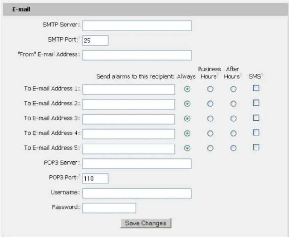
text_image
E-mail SMTP Server: SMTP Port: 25 "From" E-mail Address: Send alarms to this recipient: Always Business After SMS To E-mail Address 1: ○ ○ ○ □ To E-mail Address 2: ○ ○ ○ □ To E-mail Address 3: ○ ○ ○ □ To E-mail Address 4: ○ ○ ○ □ To E-mail Address 5: ○ ○ ○ □ POP3 Server: POP3 Port: 110 Username: Password: Save ChangesAn SMTP server as well as "From" and "To" addresses are required to send e-mails. Some mail servers may require a username and password. In most cases, the username does not have to match the "From" address, but does need to be a valid user on the authenticating server. Microsoft Exchange servers will have to be set to allow SMTP relay from the IP address of the unit. In addition, a test email can be sent from the bottom of the Monitoring tab of the Configuration page.
Note: The unit cannot receive e-mails. The POP3 server is used strictly for authentication and is not required when using None or ESMTP.
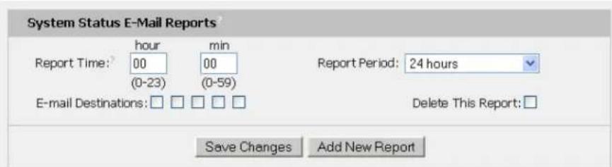
Status Reports
When enabled, the unit will periodically send a full status report to all "To" e-mail addresses selected for the report. The report includes current unit data from all attached sensors as well as alarm states. Reporting frequency options are: weekly, hourly, every 2, 3, 4, 6, 8, 12, 24, or 48 hours. E-mail addresses are selected when the report is created by checking the corresponding e-mail destination box. Allowing the cursor to hover over an e-mail destination box will display the e-mail address that the box is associated with.
text_image
System Status E-Mail Reports? Report Time: 00 (min) (0-23) (0-59) Report Period: 24 hours E-mail Destinations: □ □ □ □ Delete This Report: □ Save Changes Add New ReportSNMP
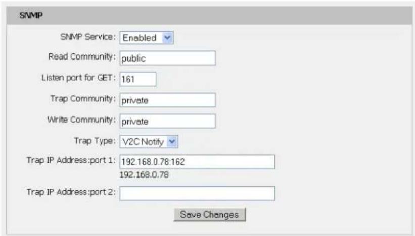
The unit supports retrieval of all data via Simple Network Management Protocol (SNMP) v1, v2c, and v3. In addition, alarm traps can be sent to up to two IP addresses. The SNMP configuration is entered on the Monitoring tab of the Configuration page.
text_image
SNMP SNMP Service: Enabled Read Community: public Listen port for GET: 161 Trap Community: private Write Community: private Trap Type: V2C Notify Trap IP Address: port 1: 192.168.0.78:162 192.168.0.78 Trap IP Address: port 2: Save Changes
text_image
Initial SNMPV3 data Unauthenticated User: initial Authenticated Manager: manager Manager Authentication Password: 12345678 Manager Privacy Password: 12345678 Trap User: Trap Trap Authentication Password: 12345678 Trap Privacy Password: 12345678 Save Changes Reset User/Access NVRAM will occur during the finish page.The default community string is "public" and the MIB is downloadable via a link at the top of the unit's web page.
Accounts and Passwords
The POU units offer account security options that are entered on the Admin tab of the Configuration page. There are three levels of account security:
- Administrator: Password protects the Display, Alarms and Configuration pages.
• Control Access: Password protects the Control Actions and Control Settings pages.
• View-Only: Password protects the Sensors, PDA, WAP and XML pages.
Name and Password Configuration
NOTE 1: If Account currently has a password, leaving Old Password blank results in no changes to that account.
NOTE 2: Administrator password may be used in the Old Password field of any account.
NOTE 3: If setting New Password to blank, Account Name must also be blank.
NOTE 4: If New Password is not blank, Account Name must not be blank.

text_image
Administrator Account Name Old Password New Password New Password Again (again, to confirm)Warning: Record your password. Loss of password may require 48 hours to recover.

text_image
Control Account Name² Old Password New Password New Password Again (again, to confirm)Warning: Record your password. Loss of password may require 48 hours to recover.

text_image
View Only Account Name Old Password New Password New Password Again (again, to confirm)Warning: Record your password. Loss of password may require 48 hours to recover.
Save Changes
User account names may include alphanumeric characters, spaces and underscores. Passwords may include alphanumeric characters and underscores.
√ Note: The Administrator account must be active to enable the Control Access and View-Only accounts.
√ Note: The Control Access account must be active to enable the View-Only account.
√ Note: The account names "root" and "admin" are disabled for security reasons and cannot be re-enabled.
Warning: Record your passwords. To reset lost passwords, follow the instructions for resetting the unit's IP address and passwords given in the Error! Reference source not found. ection. To generate a temporary recovery password to access the unit, contact customer service from a location where the unit can be accessed via the internet.
Telnet
The unit provides a Telnet server for basic monitoring via the command line. The Administrator account must be enabled to use the Telnet interface. Type "help" after logging in to the unit to see a list of available commands. The Telnet service can be disabled under "Web Server" on the Network tab of the Configuration page.
√ Note: All data sent via Telnet is unencrypted. Some settings can be changed and user names and network settings are available via Telnet. In secure environments, it is recommended that Telnet be disabled.
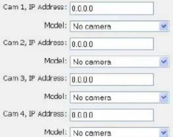
Camera Configuration
Enter the domain names/IP addresses and models of up to four IP-addressable network cameras in the "Cameras" section of the Monitoring tab on the Configuration page. The unit will present a linked snapshot from each camera on the Sensors page.

text_image
Cameras Cam 1, IP Address: 0.0.0.0 Model: No camera Cam 2, IP Address: 0.0.0.0 Model: No camera Cam 3, IP Address: 0.0.0.0 Model: No camera Cam 4, IP Address: 0.0.0.0 Model: No camera Save ChangesNote: Each camera must be set to allow anonymous access to enable this feature.
Admin Information
Information entered in the "Admin Info" section of the Admin tab of the Configuration page will show up at the bottom of the unit's web interface.

text_image
Admin Info Contact Name: Panduit Corp. Contact Email: SystemSupport@panduit.com (sysContact) Contact Phone: 866-721-5302 Device Location: Test Lab A (sysLocation) Device Description: POU 1 Networked (sysName) Save ChangesThe unit's kilowatt-hours measurements are zeroed at the factory and can be reset at any time, should it become necessary. On the Settings tab of the Control page, simply hit the button that corresponds to the desired circuit to be reset.
XML File Backup
The POU unit's configuration is stored in the XML file. The XML file can be downloaded and stored in order to backup the POU unit's current configuration settings. On the Admin tab of the Configuration page, simply hit the Download Current XML File button to download the XML file.
A previously downloaded XML file can be uploaded to the POU unit in order to restore the unit's configuration to match the configuration contained in the XML file. On the Admin tab of the Configuration page, click the Upload Local XML file button to upload a local XML file.
√ Note: XML files are unit specific. An XML file should only be uploaded to the unit that it was downloaded from.

text_image
Saved Configuration XML File? XML File: Browse... Upload Local XML File Download Current XML FileSSL Certificate Upload
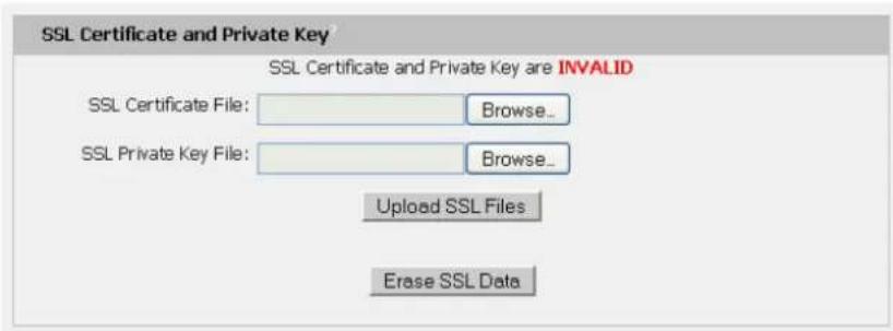
The POU will automatically generate a unique SSL Certificate and Private Key. Alternatively, a custom SSL Certificate and Private Key can be uploaded to the POU by pressing the Upload SSL Files button on the Admin tab of the Configuration page. The SSL Certificate and Private Key can be cleared by clicking the Erase SSL Data button on the Admin tab of the Configuration page.
text_image
SSL Certificate and Private Key SSL Certificate and Private Key are INVALID SSL Certificate File: Browse... SSL Private Key File: Browse... Upload SSL Files Erase SSL DataAlarms
Alarm Notifications
The POU supports three types of alarm notification:
• E-Mail: The unit can be configured to send alarm e-mails to up to five recipients.
• SNMP: The unit can be configured to send SNMP traps to up to two trap servers.
- Buzzer: When a remote display is attached, the unit can turn on an audible alarm.
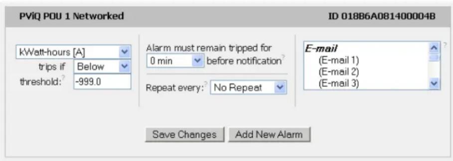
text_image
PViQ POU 1 Networked ID 018B6A081400004B kWatt-hours [A] trips if Below threshold: -999.0 Alarm must remain tripped for 0 min before notification? Repeat every: No Repeat Save Changes Add New Alarm E-mail (E-mail 1) (E-mail 2) (E-mail 3)The unit is capable of any combination of the above alarms at once. Alarm type combinations are selected per alarm via the check boxes which are displayed for each alarm on the Alarms page.
Alarm Types
The POU provides three types of alarm messages via E-Mail and SNMP:
- Trip: Occurs when a sensor value goes above a high trip threshold or below a low trip threshold.
- Clear: Occurs when a sensor already in the Tripped or Unplugged state goes back into its normal range.
- Unplugged: Occurs when a sensor with an alarm set loses contact with the main unit due to the sensor being physically unplugged or another communications error.
Alarms can be added for each internal device or external sensor displayed on the Alarms page. An alarm is added by pressing the "Add New Alarm Button" and selecting the sensor value to be monitored from a drop down menu.
Thresholds
The user must set a trip threshold and type for each alarm that is added to the Alarms page. The threshold type is chosen as either "High Trip" or "Low Trip" from a drop down menu when the alarm is created. The threshold value is typed into a data window when the alarm is created. Alarms are triggered based on the selected sensor's data and the trip threshold type and value. Alarm settings can be edited or deleted at any time.
Analysis of each unit is recommended before setting alarm thresholds as some of the values monitored by the unit are relative values, whose scale will differ slightly between units. Allow each unit to operate under normal, steady state conditions for several hours before setting alarm thresholds. By allowing the
sensors to operate for several hours, the user can better understand what the normal variations are; thereby allowing the user to choose alarm thresholds that will not trigger numerous false alarms.
√ Note: Changes in settings take a few moments to become active. Rapidly resetting alarm values may not provide the desired results. Allow up to 2 minutes after changing a setting before modifying it again.
Sensors
Overview
All internal sensors are measured every 15 seconds. External sensors are measured every 15 to 30 seconds, depending on the number of devices connected. Sensor data collected by the unit gives useful trend analysis data. While all values are not absolute in relation to a known unit, trend analysis of the data allows users to view changes and draw useful conclusions about what is happening over time in the monitored environment.
Internal Sensors
The POU contains the following onboard sensors:
- Kilowatt-Hours: Cumulative sum of Real Power.
• Volts: Measures instantaneous RMS voltage. - Volts (Peak): Reports the highest reported voltage since the last time the data was updated, typically every 15 seconds.
- Amps: Measures instantaneous RMS current.
- Amps (Peak): Reports the highest reported current since the last time the data on the screen was updated, typically every 15 seconds.
• Real Power: Average of instantaneous voltage and current over the last 1.5 seconds. - Apparent Power: The product of instantaneous RMS Voltage and RMS Current. This is the value used by circuit breakers.
• Power Factor: The ratio of Real Power to Apparent Power.
Remote Sensors
Available Sensors
• PVQ-EST-12: Environmental sensor: Temperature
• PVQ-ESTAFHD-12: Environmental sensor: Temperature / Air Flow / Humidity / Dew Point
Please contact Panduit Technical Support if you need assistance locating your current version or upgrading to the new firmware version
Connecting Remote Sensors
Plug-and-play remote sensors may be attached to the unit at any time via the RJ-12 connectors on the face of the unit. In some cases splitters may be required to add additional sensors. Each sensor has a unique serial number and is automatically discovered and added to the web page. Up to sixteen sensors may be connected.
The display order of the sensors on the web page is determined by the serial number of each sensor. Friendly names for each sensor can be customized on the Display page.
√ Note: The sensor uses Cat. 3 wire and RJ12 connectors. Wiring must be straight-through: reverse polarity will temporarily disable all sensors until corrected.
√ Note: The sensors use a serial communication protocol and are subject to network signaling constraints dependent on shielding, environmental noise, and length of wire. Typical installations allow runs of up to 600 feet of sensor wire.
Data Logging and Display
All data collected by the unit can be graphed, except kilowatt-hours. The Logging page allows the user to select graphed content to be logged. Selected sensor values are logged into the data file at a rate of one point per minute and will be displayed on the optional Remote Display. The number of selected sensors determines the maximum data logging time span. This period is calculated and displayed on the Logging page. The oldest data will be deleted when the onboard memory fills up in order to make room for new data.
Accessories
Remote Display
This small module can be mounted in an accessible spot inside or outside the rack or cabinet. A backlit LCD display scrolls the values of items selected on the Logging page. The display is connected to the main unit via a 4-conductor handset-style cord. The display's onboard buzzer can be used in conjunction with E-Mail and SNMP to provide local alarming of error conditions. The buzzer can be silenced via the button on the face of the module; however the display's LED indicator will remain lit until the alarm condition is cleared.
IP-Addressable Network Cameras
The unit is able to interface with up to four IP-addressable network cameras. A live snapshot from each camera will be displayed on the unit's Sensors page underneath the main unit's graph. Clicking on a snapshot opens the camera's website in a new browser window.
Camera model and IP address are entered on the Monitoring tab of the Configuration page.

Note: Some cameras require additional software downloads to display live video in a web browser.
Alternate Data Formats
In addition to the full access, control and configuration available via a desktop web browser, PViQ Networked and Environmental POUs products present data in multiple formats for easy integration with other monitoring systems. Data formats available via links on the unit's web page are:
PDA/Phone | XML | MIB
• PDA/Phone: Presents data in a format best-suited for PDA or cellular phone web browsers.
- XML: Extensible Markup Language. Presents data in a structured tree for use with automated scripts and monitoring systems.
• MIB: Management Information Base. Downloads the MIB for use with SNMP monitoring tools.
Service and Technical Support
Firmware Version
The firmware version is located in the upper right section of the web interface header, represented by v3.y.xx.
PViQ POU 1 Networked
IP Address: 192.168.1.111
Local Time: Thu, 12/09/10 14:11:43
PViQ POU 1 Networked v3.5.6
All is well: 1 Alarms monitored
Before contacting support, Panduit recommends the POU first be updated to the latest firmware version. If this is not possible, please have the existing firmware version number for the unit available when contacting technical support.
Firmware Updates
Keep your unit updated with the latest firmware releases or sign up for notifications. Contact Panduit Technical Support for information on updating your firmware, or visit the following website:
http://www.panduit.com/Support/MNSTechSupport/index.htm
Resetting POU
Should the POU lose communication, the processor may be manually rebooted without affecting power to the outlets. Pressing the 'Reset' button on the face of the unit will cause the processor to reboot. The web interface will remain off-line during boot up.
Service
No service or maintenance is required. Do not attempt to open the POU or you may void the warranty. No serviceable parts inside. Panduit recommends that power be removed from the unit before installing or removing any equipment.
Technical Support
For Technical Support on the PViQ POU please contact Panduit Technical Support using one of the following methods:
• 1-800-777-3300 (toll-free)
• cs@panduit.com
- http://www.panduit.com/Support/MNSTechSupport/index.htm