
PDA-5004 - Audio Amplifier PIONEER - Free user manual and instructions
Find the device manual for free PDA-5004 PIONEER in PDF.

| Product Type | Video extension card for plasma display |
| Brand | Pioneer |
| Model | PDA-5004 |
| Dimensions (W x H x D) | 301.5 x 27.6 x 148.3 mm |
| Weight | 0.4 kg |
| Video inputs | 3 additional inputs (INPUT3, INPUT4, INPUT5): S-Video, composite, component YPbPr, analog RGB |
| Video outputs | 1 composite video output (INPUT4 OUT) |
| Audio inputs | 3 RCA pairs (INPUT3, INPUT4, INPUT5): 500 mV rms, impedance >10 kΩ |
| Audio outputs | Via the plasma display (speaker terminals and line out) |
| Main functions | Addition of extra video/audio inputs, HD signal compatibility (1080i, 720p), image and screen settings, orbiter, screen saver, power management |
| Display compatibility | Pioneer PDP-505CMX, PDP-504CMX, PDP-50MXE10, PDP-50MXE11, PDP-50MXE1, PDP-50MXE1-S, PDP-434CMX, PDP-43MXE1, PDP-43MXE1-S |
| Power supply | Powered by the plasma display via the extension connector |
| Safety | Do not open, risk of electric shock; installation by a professional |
| Maintenance and cleaning | Clean with a soft cloth, avoid solvents |
| Spare parts and repairability | No user-serviceable parts; refer servicing to qualified technician |
| Supplied accessories | Labels for remote control and connector, 2 mounting screws, user manual |
Frequently Asked Questions - PDA-5004 PIONEER
User questions about PDA-5004 PIONEER
0 question about this device. Answer the ones you know or ask your own.
Ask a new question about this device
Download the instructions for your Audio Amplifier in PDF format for free! Find your manual PDA-5004 - PIONEER and take your electronic device back in hand. On this page are published all the documents necessary for the use of your device. PDA-5004 by PIONEER.
USER MANUAL PDA-5004 PIONEER
Operating Instructions
Mode d'emploi
Bedienungsanleitung
「据付工事」にて
This is the most important and most useful way to use this kind of text.
(2) COMBINATION IN/OUT
⑰ ANALOG RGB (INPUT5) (BNC端子)
⑱ AUDIO R/L (INPUT5) (RCAにんじually)
23 AUDIO R/L (INPUT4) (RCAにんジually)
This is the way of adjusting the input voltage.
「映像の調整」の調整項目
RGB…0.7Vp-p/75Ω/同期怎U
G ON SYNC…1Vp-p/75Ω/同期負
- メンボーネnts映像信号
Y…1Vp-p/75Ω/同期負
The lightning flash with arrowhead symbol, within an equilateral triangle, is intended to alert the user to the presence of uninsulated "dangerous voltage" within the product's enclosure that may be of sufficient magnitude to constitute a risk of electric shock to persons.
CAUTION
RISK OF ELECTRIC SHOCK DO NOT OPEN
CAUTION:
TO PREVENT THE RISK OF ELECTRIC SHOCK,DO NOT REMOVE COVER (OR BACK).NO USER-SERVICEABLE PARTS INSIDE.REFER SERVICING TO QUALIFIED SERVICE PERSONNEL.

The exclamation point within an equilateral triangle is intended to alert the user to the presence of important operating and maintenance (servicing) instructions in the literature accompanying the appliance.
D3-4-2-1-1 En-A
To ensure proper heat radiation, distance the unit slightly from other equipment, walls, etc. (normally more than 10cm ). Avoid the following installations which will block vents and cause heat to build up inside, resulting in fire hazards.
- Do not attempt to fit the unit inside narrow spaces where ventilation is poor
- If planning special installation such as fitting close to the wall, placing it horizontally, etc., be sure to consult your Pioneer dealer first.
WARNING: The apparatus is not waterproofs, to prevent fire or shocks hazard, do not expose this apparatus to rain or moisture and do not put any water source near this apparatus, such as vase, flower pot, cosmetics container and medicine bottle etc. D3-4-2-1-3_
This product complies with the EMC Directives (89/336/EEC, amended by 92/31/EEC and 93/68/EEC). D3-4-2-1-9b_En
[For U.S. model]
IMPORTANT NOTICE - THE SERIAL NUMBER FOR THIS EQUIPMENT IS LOCATED IN THE BACK. PLEASE WRITE THIS SERIAL NUMBER ON YOUR ENCLOSED WARRANTY CARD AND KEEP IN A SECURE AREA. THIS IS FOR YOUR SECURITY. D1-4-2-6-1_EN
NOTE: This equipment has been tested and found to comply with the limits for a Class B digital device, pursuant to Part 15 of the FCC Rules. These limits are designed to provide reasonable protection against harmful interference in a residential installation. This equipment generates, uses, and can radiate radio frequency energy and, if not installed and used in accordance with the instructions, may cause harmful interference to radio communications. However, there is no guarantee that interference will not occur in a particular installation. If this equipment does cause harmful interference to radio or television reception, which can be determined by turning the equipment off and on, the user is encouraged to try to correct the interference by one or more of the following measures:
- Reorient or relocate the receiving antenna.
- Increase the separation between the equipment and receiver.
- Connect the equipment into an outlet on a circuit different from that to which the receiver is connected.
- Consult the dealer or an experienced radio/TV technician for help.
D8-10-1-2_En
FEDERAL COMMUNICATIONS COMMISSION DECLARATION OF CONFORMITY
This device complies with part 15 of the FCC Rules. Operation is subject to the following two conditions: (1) This device may not cause harmful interference, and (2) this device must accept any interference received, including interference that may cause undesired operation.
Product Name: Plasma Display with Video Card
Model Number: PDP-505CMX/PDP-504CMX/PDP-434CMX (Plasma Display)
PDA-5003/PDA-5004 (Video Card)
Product Category: Class B Personal Computers & Peripherals
Responsible Party Name: PIONEER ELECTRONICS (USA) INC. Customer Support Division
Address: P.O. BOX 1760, LONG BEACH, CA., 90801-1760 U.S.A.
Phone: (800)421-1625
URL http://Pioneerelectronics.com
This Class B digital apparatus complies with Canadian ICES-003.
Alteration or modifications carried out without appropriate authorization may invalidate the user's right to operate the equipment. D8-10-2_En
CAUTION: This product satisfies FCC regulations when shielded cables and connectors are used to connect the unit to other equipment. To prevent electromagnetic interference with electric appliances such as radios and televisions, use shielded cables and connectors for connections. D8-10-3
The following symbols are found on labels attached to the product. They alert the operators and service personnel of this equipment to any potentially dangerous conditions.
WARNING
This symbol refers to a hazard or unsafe practice which can result in personal injury or property damage.
CAUTION
This symbol refers to a hazard or unsafe practice which can result in severe personal injury or death.
詠詠 而是 之言的 郎而有 味合
Notes on Installation Work:
This product is marketed assuming that it is installed by qualified personnel with enough skill and competence. Always have an installation specialist or your dealer install and set up the product. PIONEER cannot assume liabilities for damage caused by mistake in installation or mounting, misuse, modification or a natural disaster.
Note for Dealers:
After installation, be sure to deliver this manual to the customer and explain to the customer how to handle the product.
Thank you very much for purchasing this PIONEER product. Before using this unit, please carefully read the "Safety Precautions" and these "Operating Instructions" so you will know how to operate the Plasma Display properly. Keep this manual in a safe place. You will find it useful in the future.
The PDA-5003/PDA-5004 is a video card designed for exclusive use with the Pioneer Plasma Display PDP-505CMX/PDP-504CMX/PDP-50MXE10/PDP-50MXE11/PDP-50MXE1/PDP-50MXE1-S (or PDP-434CMX/PDP-43MXE1/PDP-43MXE1-S). The PDP-505CMX/PDP-504CMX/PDP-50MXE10/PDP-50MXE11/PDP-50MXE1/PDP-50MXE1-S (or PDP-434CMX/PDP-43MXE1/PDP-43MXE1-S) plasma display has been originally designed as a computer monitor, but by installing the optional PDA-5003/PDA-5004 video card, the following supplementary features are produced:
- Allows use of additional input jacks (INPUT 3, 4, 5) supporting S-Video, composite video, component video and analog RGB singals.
- Allows connection to a wide variety of optional video equipment.
Contents
Safety Precautions
Before Proceeding 2
Checking supplied accessories 2
How to use this manual 2
Part Names and Functions 4
Connection panel 4
Installation and Connections 6
Installing the video card 6
Input connectors on the plasma display with video card 7
Connection to INPUT1 and INPUT5 7
Connection to INPUT1 or INPUT5 8
Connection to INPUT2 13
Connection to INPUT3 13
Connection to INPUT4 13
About DTV set top box connection 14
Audio connections 15
How to route cables 17
System Settings 18
Setting the onscreen display language 18
Settings after connections 19
Operation 22
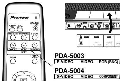
Selecting input source 22
Adjusting sound volume 23
Muting the sound 23
Confirming current status 23
Changing screen size 24
Enlarging one part of the screen (POINT ZOOM) .... 25
Multiscreen display 26
Automatic power-off (POWER MANAGEMENT) .... 27
PICTURE/SCREEN Adjustment 28
PICTURE adjustment 28
Adjusting screen POSITION, CLOCK, and PHASE
Adjusting screen POSITION, CLOCK, and PHASE
Other Operations 32
Setting the orbiter (ORBITER) 32
Side mask position (MASK CONTROL) 32
Screen management settings (SCREEN MGT.) 33
Energy saving settings (ENERGY SAVE) 34
Changing the color temperature (COLOR TEMP.)..... 35
Reducing video noise (DNR) 36
Reducing noise in MPEG images (MPEG NR) 37
Increasing color border contrast (CTI) 38
Setting the PURECINEMA mode 39
Setting the COLOR SYSTEM 40
Automatic input switching (AUTO FUNCTION) 41
About audio output (AUDIO OUT)
(PDP-504CMX/PDP-50MXE1/PDP-50MXE1-S and PDP-434CMX/PDP-43MXE1/PDP-43MXE1-S only) ..... 42
Additional Information 43
Specifications 43
Appendix 1 44
Appendix 2 45
Appendix 3 47
Appendix 4 48
Explanation of Terms 49
Checking supplied accessories
Check that the following accessories were supplied.
① Label for remote control unit PDA-5003
③ Screws (× 2) (Accessory screws for installing video card)

These Operating Instructions
Warranty
How to use this manual
This manual has been written to allow easy understanding of setup and operating procedures when the video card PDA-5003/PDA-5004 is installed in the plasma display.
Remove the video card from its packaging and confirm that all accessory parts are present. While installing and setting up the video card, consult the section "Part Names and Functions" starting on page 4 of this manual and in the plasma display's Operating Instructions to familiarize yourself with the parts of the respective devices. Since this manual makes frequent reference to the names of operating buttons on the plasma display, use the display's Operating Instructions to familiarize yourself with the controls on the display and the remote control unit.
The section "Installation and Connections" starting on page 6 includes information necessary for installing the video card on the plasma display, together with instructions regarding connections to various other components.
The section "System Settings" starting on page 18 covers the on-screen settings necessary for correct operation of the plasma display with its connected components. Depending on the connections made, this section may or not be necessary.
The remainder of the sections in this manual is dedicated to the basic operations associated with selecting a source component up to the more complex operations associated with adjusting the plasma display picture to match the requirements of specific components and personal preferences.
Regarding menu displays
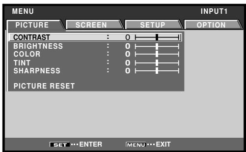
The example menu displays provided in this manual are those for the PDP-505CMX/PDP-504CMX/PDP-50MXE10/ PDP-50MXE11/PDP-50MXE1/PDP-50MXE1-S model. The PDP-434CMX/PDP-43MXE1/PDP-43MXE1-S display differs as shown:
Please note that the actual contents displayed are the same for both the PDP-505CMX/PDP-504CMX/PDP-50MXE10/PDP-50MXE11/PDP-50MXE1/PDP-50MXE1-S and PDP-434CMX/PDP-43MXE1/PDP-43MXE1-S.
Certain menu layouts differ between PDP-505CMX/PDP-50MXE10/PDP-50MXE11 and PDP-504CMX/PDP-50MXE1/PDP-50MXE1-S.
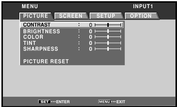
Example of PDP-505CMX/PDP-504CMX/PDP-50MXE10/ PDP-50MXE11/PDP-50MXE1/PDP-50MXE1-S Menu Display:
Example of PDP-434CMX/PDP-43MXE1/PDP-43MXE1-S Menu Display:
About operations in this manual
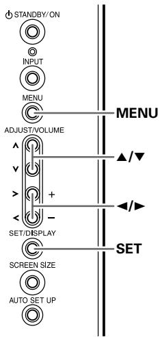
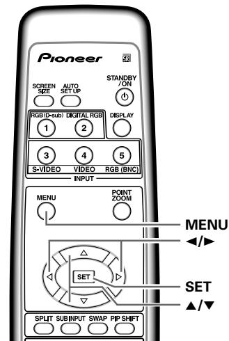
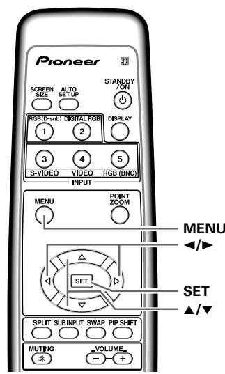
Each operation is described in its proper operating order. These Operating Instructions will refer to the operating controls found on the remote control unit, with the exception of those buttons found only on the main plasma display itself. When the plasma display controls include equivalent buttons to those found on the remote control unit, the commands can be performed on the main unit as well.
The following illustrations are an example of the actual operations used for the section "PICTURE adjustment". The examples are provided to allow you to confirm whether the operation is performed correctly or not.
Note
The screen images depicted in these Operating Instructions should be considered typical images; some difference will be seen in practice, depending on the screen item displayed and its contents, the input source and various other control settings.
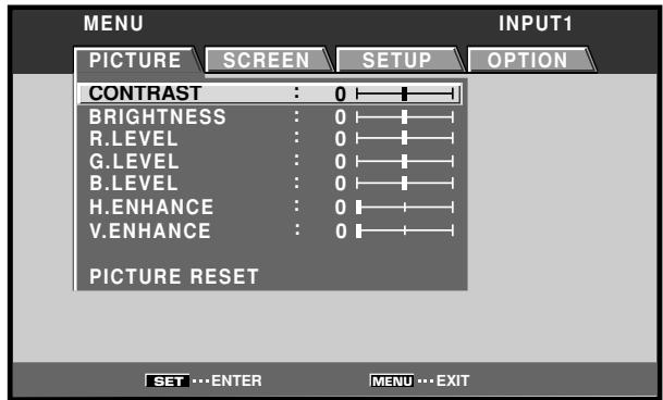
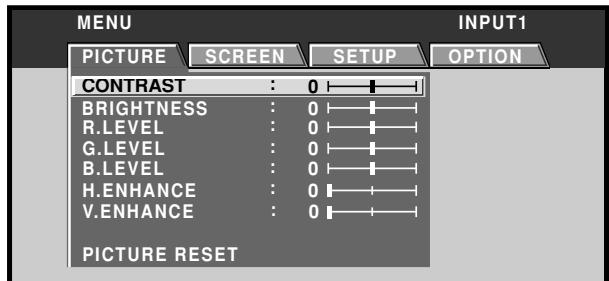
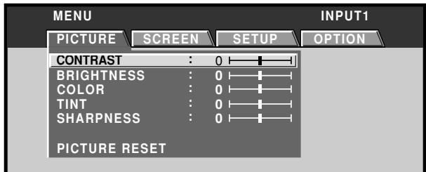
PICTURE/SCREEN Adjustment
PICTURE adjustment
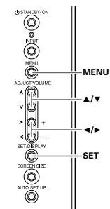
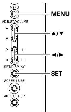
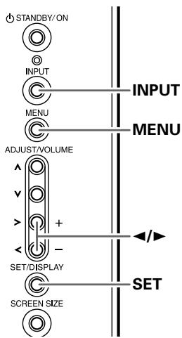
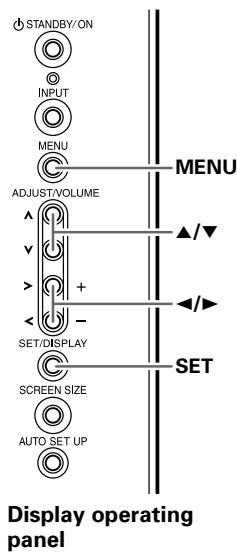
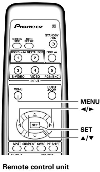
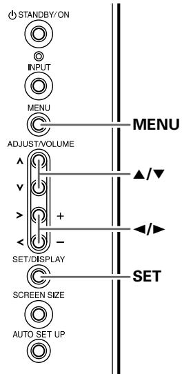
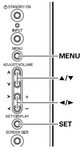
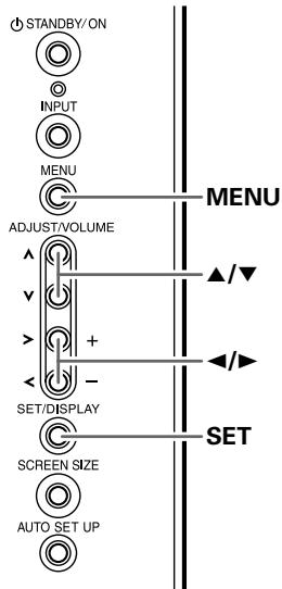
Display operating panel
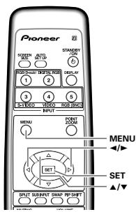
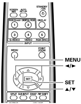
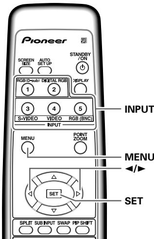
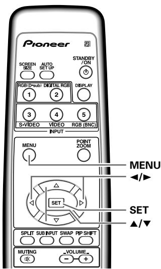
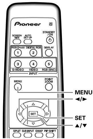
Remote control unit

1 Press the MENU button to display the menu screen.
2 Use the / buttons to select the adjustment item, then press the SET button.
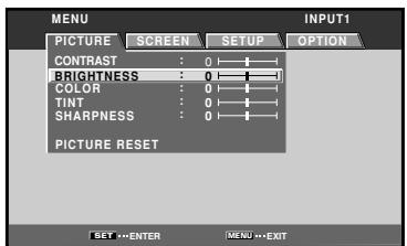

3 Use the / buttons to adjust the picture quality as desired.
28
En
4 Press the SET button.
Pressing the SET button writes the value into the memory and returns the display to the step 2 screen.
5 When the setup is finished, press the MENU button to exit the menu screen.
Note
Make these adjustments for each input (INPUT1 to INPUT5) and signals.
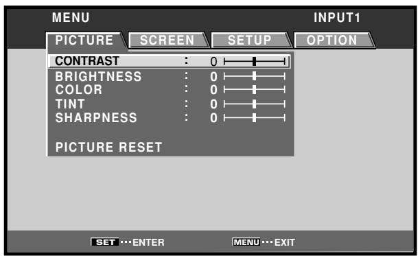
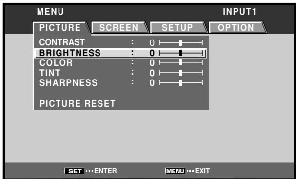
[PICTURE] mode adjustment items
Below are brief descriptions of the options that can be set in the [PICTURE] mode.
CONTRAST Adjust according to the surrounding brightness so that the picture can be seen clearly.
BRIGHTNESS Adjust so that the dark parts of the picture can be seen clearly.
COLOR Adjust to the desired depth (Setting to a slightly deep color will create a natural looking picture).
TINT Adjust so that flesh tones look normal.
SHARPNESS Normally set to the center position. To create a softer picture, set to the left of center. To create a sharper picture, set to the right of center.
Note
Consult the Operating Instructions for your Plasma Display regarding PICTURE adjustment when inputting computer signals.
To reset [PICTURE] mode settings to the default If settings have been adjusted excessively or the picture on the screen no longer appears natural, it may prove more beneficial to reset the [PICTURE] mode to default settings instead of trying to make adjustments under already adjusted conditions.
1 In step 2 in the previous procedure, use the / buttons to select [PICTURE RESET], then press the SET button.
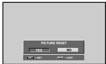
2 Use the / buttons to select [YES], and press the SET button.
All [PICTURE] mode settings are returned to the factory set default.
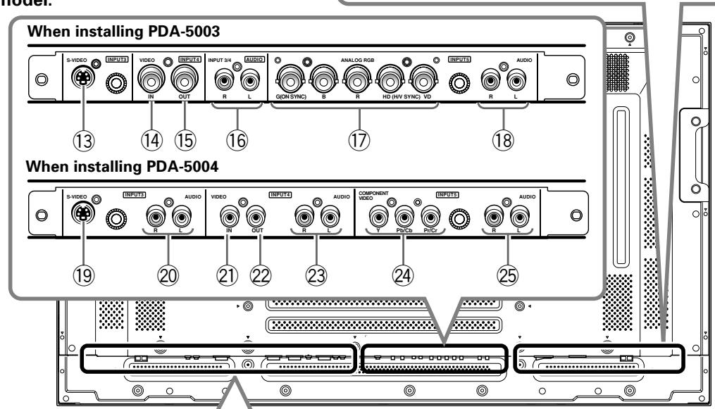
Connection panel
Illustration depicts PDP-505CMX/PDP-504CMX/ PDP-50MXE10/PDP-50MXE11/PDP-50MXE1/ PDP-50MXE1-S model.
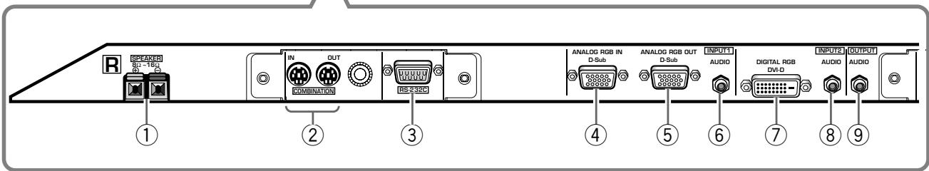
Plasma Display Section
The plasma display is provided with 2 video input connectors, 1 video output connector, audio input/output jacks and speaker terminals.
When this video card is installed on a plasma display, an additional three sets of video input connectors are provided (total five), together with one additional video output connector (total two). See the pages noted in parentheses () or the plasma display's Operating Instructions for details regarding connections to the various jacks and connectors.
① SPEAKER (R) terminal
For connection of an external right speaker. Connect a speaker whose impedance is 8 -
② COMBINATION IN/OUT
Never connect any component to these connectors without first consulting your Pioneer installation technician.
These connectors are used for plasma display setup adjustments.
③ RS-232C
Never connect any component to this connector without first consulting your Pioneer installation technician.
This connector is used for plasma display setup adjustments.
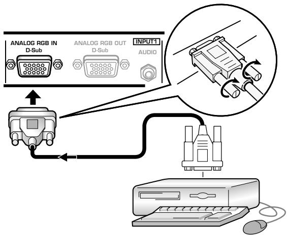
④ ANALOG RGB IN (INPUT1) (mini D-sub 15 pin)
For connecting components equipped with RGB outputs jacks, such as a personal computer or external RGB decoder; or components equipped with component output jacks, such as a DVD recorder.
Make sure that the connection made corresponds to the format of the signal output from the connected component (pages 7 to 10).
⑤ ANALOG RGB OUT (INPUT1) (mini D-sub 15 pin)
Use the ANALOG RGB OUT (INPUT1) connector to output the video signal to an external monitor or other component.
Note: The video signal will not be output from the ANALOG RGB OUT (INPUT1) connector when the main power of this display is off or in standby mode (page 10).
Use to obtain sound when INPUT1 is selected. Connect this jack to the audio output connector of the device connected to the plasma display's INPUT1 (page 15).
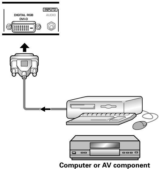
⑦ DIGITAL RGB (INPUT2) (DVI-D jack)
Use to connect to a computer. With the PDP-505CMX/PDP-50MXE10/PDP-50MXE11, it can also be used to connect to an AV component (HDCP-compliant) equipped with DVI output.
Note: PDP-504CMX/PDP-50MXE1/PDP-50MXE1-S and PDP-434CMX/PDP-43MXE1/PDP-43MXE1-S do not support the display of HDCP or other copyguard-protected video signals (page 13).
Use to obtain sound when INPUT2 is selected. Connect this jack to the audio output connector of the device connected to the plasma display's INPUT2 (page 15).
⑨ AUDIO (OUTPUT) (Stereo mini jack)
Use to output the audio of the selected source component connected to the plasma display to an AV amplifier or similar component.
Note: No sound is produced from the AUDIO (OUTPUT) jack when the MAIN POWER switch is set to OFF or ON (standby) (page 15).
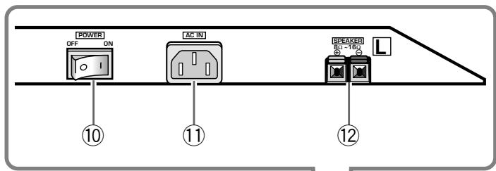
10 MAIN POWER switch
Use to switch the main power of the plasma display on and off.
1 AC IN
A power cable is furnished with the plasma display; connect one end of the power cable to this connector, and the other end to a standard AC power source.
12 SPEAKER (L) terminal
For connection of an external left speaker. Connect a speaker that has an impedance of 8 -16 Ω.
Video Card Section
The video card is provided with 3 video input connectors, 1 video output connector, and 2 audio input connectors. Consult the pages noted in parentheses () for details regarding connections to the various jacks and connectors.
⑬ S-VIDEO (INPUT3) (S-video jack)
For connection of components that have an S-video output jack such as a video deck, video camera, laser disc player, or DVD recorder (page 13).
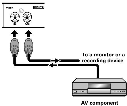
⑭VIDEO IN (INPUT4) (BNC jack)
For connection of components that have a composite video output jack such as a video deck, video camera, laser disc player, or DVD recorder (page 13).
⑤VIDEO OUT (INPUT4) (BNC jack)
Use the VIDEO OUT (INPUT4) jack to output the video signal to an external monitor or other component.
Note: The video signal will not be output from theVIDEO OUT (INPUT4) jack when the main power of this display is off or in standby mode (page 13).
16 AUDIO R/L (INPUT3/4) (RCA Pin jacks)
Use to obtain sound when INPUT3 or INPUT4 is selected. Connect these jacks to the audio output connectors of components connected to the video card's INPUT3 or INPUT4 (page 16).
⑰ ANALOG RGB (INPUT5) (BNC jacks)
For connecting components equipped with RGB outputs jacks, such as a personal computer or external RGB decoder; or components equipped with component output jacks, such as a DVD recorder. Make sure that the connection made corresponds to the format of the signal output from the connected component (pages 7 to 10).
18 AUDIO R/L (INPUT5) (RCA Pin jacks)
Use to obtain sound when INPUT5 is selected. Connect these jacks to the audio output connectors of components connected to the video card's INPUT5 (page 15).
Video Card Section
The video card is provided with 3 video input connectors, 1 video output connector, and 3 audio input connectors. Consult the pages noted in parentheses ( ) for details regarding connections to the various jacks and connectors.
19 S-VIDEO (INPUT3) (S-video jack)
For connection of components that have an S-video output jack such as a video deck, video camera, laser disc player, or DVD recorder (page 11).
20 AUDIO R/L (INPUT3) (RCA Pin jacks)
Use to obtain sound when INPUT3 is selected. Connect these jacks to the audio output connectors of components connected to the video card's INPUT3 (page 16).
②VIDEO IN (INPUT4) (RCA Pin jack)
For connection of components that have a composite video output jack such as a video deck, video camera, laser disc player, or DVD recorder (page 13).
22VIDEO OUT (INPUT4) (RCA Pin jack)
Use the VIDEO OUT (INPUT4) jack to output the video signal to an external monitor or other component.
Note: The video signal will not be output from the VIDEO OUT (INPUT4) jack when the main power of this display is off or in standby mode (page 13).
23 AUDIO R/L (INPUT4) (RCA Pin jacks)
Use to obtain sound when INPUT4 is selected. Connect these jacks to the audio output connectors of components connected to the video card's INPUT4 (page 16).
24 COMPONENTVIDEO(INPUT5) (RCA Pinjacks)
For connection of components that have component video output jacks such as a DVD recorder (pages 7 and 8).
25 AUDIO R/L (INPUT5) (RCA Pin jacks)
Use to obtain sound when INPUT5 is selected. Connect these jacks to the audio output connectors of components connected to the video card's INPUT5 (page 15).
Installing the video card
TO USERS:
This component is sold with the understanding that it will be installed by a specialist possessing appropriate technical knowledge and ability.
TO SALES AGENTS:
Installation instructions are noted below. When installing the unit, if a screw or other object should drop inside the plasma display, immediately consult your nearest Pioneer Service Center.
Continuing operation may result in malfunction.
This device has been designed for installation on the Pioneer Plasma Display PDP-505CMX/PDP-504CMX/PDP-50MXE10/PDP-50MXE11/PDP-50MXE1/PDP-50MXE1-S or PDP-434CMX/PDP-43MXE1/PDP-43MXE1-S. Installation procedures are as follows:
Confirm the following before installing this video card:
- Disconnect the plasma display from computer or other components.
- Disconnect the plasma display's power cord from its outlet.
Installation Notes:
- When opening the protective cover, take care not to drop screws or other objects in the opening. Objects dropped inside the display may cause damage or malfunction.
- When installing the video card, if the plasma display is laid with its screen side facing down, the work surface should be flat and level, and either the packing material, a blanket, or other soft material should be spread on the work surface first to protect the screen. Take care to prevent scratches or other damage to the unit from tools or other objects. Never rest the display on a surface in such a way that weight or pressure is placed only on the screen surface.
- This video card has been designed for exclusive use with the Pioneer Plasma Display PDP-505CMX/PDP-504CMX/PDP-50MXE10/PDP-50MXE11/PDP-50MXE1/PDP-50MXE1-S or PDP-434CMX/PDP-43MXE1/PDP-43MXE1-S. Do not attempt unauthorized modifications or alterations since malfunction or damage may result.
- Take care not to modify or damage the card's internal devices in any way.
- Before installation, take precautions to eliminate static electricity on your body. Do not touch the card's circuitry or devices.
- This device has not been designed to allow reinstalling or removal; after the card has once been installed on the plasma display, do not attempt to remove it since damage may result.
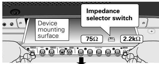
- When installing the PDA-5003, it may be necessary to adjust the setting of the impedance selector switch. Confirm this item before installing (pages 10, 12).
- Do not install the PDA-5002 on the PDP-505CMX/PDP-504CMX/PDP-50MXE10/PDP-50MXE11/PDP-50MXE1/PDP-50MXE1-S or PDP-434CMX/PDP-43MXE1/PDP-43MXE1-S display units.
Installation
Illustration depicts PDA-5003 model.
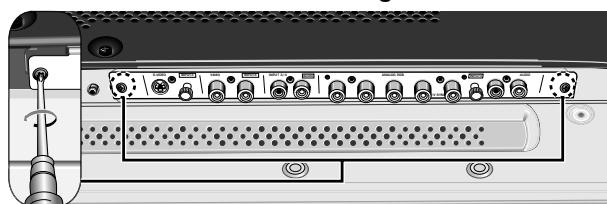
1 Remove the protective cover over the video card slot on the plasma display's terminal panel.
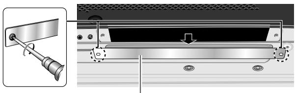
Protective cover
2 Insert the video card gently and evenly in alignment with the two rails visible inside the installation port.
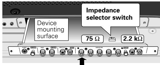
Notes
- Be very careful when inserting the card. Install the card's device mounting surface oriented toward the rear side of the plasma display. Insert straight! The card or display may be damaged if the card is inserted crooked or with excessive force.
- Impedance selector switch is found on PDA-5003 only.
3 After inserting the video card all the way into the slot, confirm that it is seated securely, then use the screws removed in step 1 to secure the card in place.
4 Affix the accessory connector indicator label to the plasma display, and affix the remote control unit label to the remote control unit furnished with the plasma display.
Note
Use a soft cloth to gently wipe away any dust or soiling from the surface before affixing the label.
Video Card Removal (In principle, removal of the video card should not be attempted).
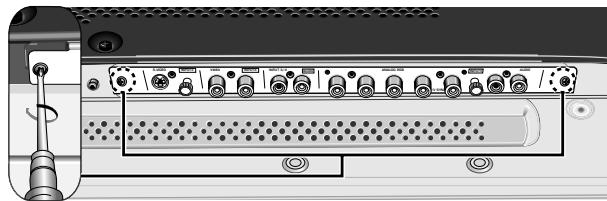
1 Remove the two screws holding the video card.
2 Holding the inside tabs, pull the video card out straight.
Input connectors on the plasma display with video card
Consult the following chart when making connections to a plasma display equipped with this video card (pages 7 to 16).
| Connected component and signals\Input Connector | INPUT 1*1 | INPUT 2 | INPUT 3 | INPUT 4 | INPUT 5*1 |
| AV component | |||||
| Analog RGB | ○ | ○ | |||
| Component video | ○ | ○ | |||
| S video | ○ | ||||
| Composite video | ○ | ||||
| Digital RGB | ○ *5 | ||||
| Personal computer (PC) | |||||
| Analog RGB | ○*2 | ○ | |||
| S video | ○ *3 | ||||
| Composite video | ○ *3 | ||||
| Digital RGB | ○ *4 |
1 Although INPUT1 and INPUT5 are compatible with various kinds of signals, setup using the on-screen menu is necessary after connections are made in order to match the characteristics of the source component (pages 18 to 21).
2 INPUT1 is compatible with Microsoft's Plug & Play (VESA DDC 1/2B).
3 Depending on the video output board of the computer, this type of connection may not be possible.
4 INPUT2 is compatible with Microsoft's Plug & Play (VESA DDC 2B).
*5 Supports only PDP-505CMX/PDP-50MXE10/PDP-50MXE11.
When using PDA-5004
Connection to INPUT1 and INPUT5
Various components can be connected to the INPUT1 and INPUT5 jacks. After connections are made, on-screen setup is necessary to match the characteristics of the connected component. Please see pages 18 to 21 for on-screen setup after connection.
| INPUT5 jack Output source | [ON SYNC] G | B | R | [H/V SYNC] HD | VD |
| Video component/personal computer (PC) with RGB output | ○ G ON SYNC | ○ B | ○ R | × | × |
| ○ G | ○ B | ○ R | ○ H/V SYNC | × | |
| ○ G | ○ B | ○ R | ○ HD | ○ VD | |
| Video component with component video output | ○ Y | ○ PB/CB | ○ PR/CR | × | × |
× : Do not connect anything. : Connect to this jack.
Note
Components compatible with INPUT1 are also compatible with INPUT5. When making connections to INPUT1, please refer to the plasma display's Operating Instructions.
See Appendixes 1 and 2 (pages 44 to 46) for information regarding signals and display formats supported by INPUT1 and INPUT5.
Input connectors on the plasma display with video card
Consult the following chart when making connections to a plasma display equipped with this video card (pages 7 to 16).
| Connected component and signals\Input Connector | INPUT 1*1 | INPUT 2 | INPUT 3 | INPUT 4 | INPUT 5*1 |
| AV component | |||||
| Analog RGB | ○ | ○ | |||
| Component video | ○ | ○ | |||
| S video | ○ | ||||
| Composite video | ○ | ||||
| Digital RGB | ○ *5 | ||||
| Personal computer (PC) | |||||
| Analog RGB | ○ *2 | ○ | |||
| S video | ○ *3 | ||||
| Composite video | ○ *3 | ||||
| Digital RGB | ○ *4 |
1 Although INPUT1 and INPUT5 are compatible with various kinds of signals, setup using the on-screen menu is necessary after connections are made in order match the characteristics of the source component (pages 18 to 21).
2 INPUT1 is compatible with Microsoft's Plug & Play (VESA DDC 1/2B).
3 Depending on the video output board of the computer, this type of connection may not be possible.
4 INPUT2 is compatible with Microsoft's Plug & Play (VESA DDC 2B).
*5 Supports only PDP-505CMX/PDP-50MXE10/PDP-50MXE11.
When using PDA-5004
Connection to INPUT1 and INPUT5
Various components can be connected to the INPUT1 and INPUT5 jack. After connections are made, on-screen setup is necessary to match the characteristics of the connected component. Please see pages 18 to 21 for on-screen setup after connection.
| INPUT5 jack Output source | Y | PB/CB | PR/CR |
| Video component/personal computer (PC) with RGB output | ○ G ON SYNC | ○ B | ○ R |
| Video component with component video output | ○ Y | ○ PB/CB | ○ PR/CR |
: Connect to this jack.
Note
When making connections to INPUT1, please refer to the plasma display's Operating Instructions.
See Appendixes 1 and 2 (pages 44 to 46) for information regarding signals and display formats supported by INPUT1.
Connection to INPUT1 or INPUT5
When using PDA-5003
Connection to AV components
Connection to AV component equipped with component video jacks
Make component video connections for AV components equipped with component video jacks.
When connecting to ANALOG RGB IN (INPUT1)
On-screen setup is necessary after connection.
Please see pages 18 to 21.
When connecting to ANALOG RGB (INPUT5)
Connect the Y signal to the G jack, the PB / CB signal to the B jack, and the Pr / Cr signal to the R jack.
On-screen setup is necessary after connection.
Please see pages 18 to 21.
INPUT5 jacks are all BNC jacks.
If necessary, use commercially available BNC/pin-plug conversion adapters to make connections.
Note
The plasma display and this Video Card are designed to support component video signals with standard, stable signal levels and sync signals. As a result, some image disruption may be generated during use of various special trick play functions on video components.
When using PDA-5004
Connection to AV components
Connection to AV component equipped with component video jacks
Make component video connections for AV components equipped with component video jacks.
When connecting to ANALOG RGB IN (INPUT1)
On-screen setup is necessary after connection.
Please see pages 18 to 21.
When connecting to COMPONENTVIDEO(INPUT5) —
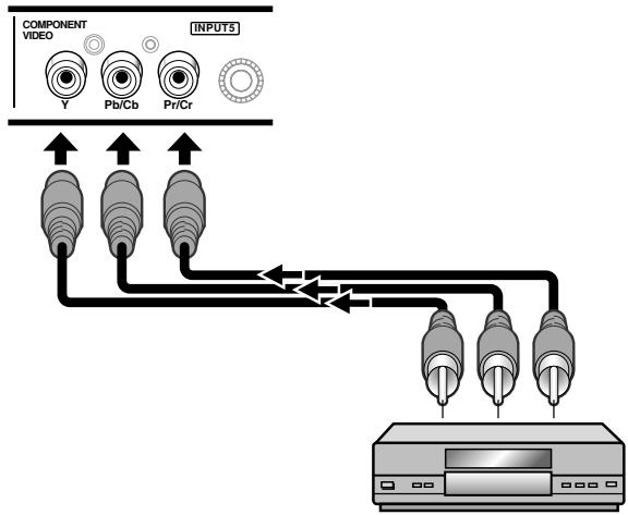
Connect the Y signal to the Y jack, the PB / CB signal to the PB / CB jack, and the PR / CR signal to the PR / CR jack.
Note
The plasma display and this Video Card are designed to support component video signals with standard, stable signal levels and sync signals. As a result, some image disruption may be generated during use of various special trick play functions on video components.
Connection of G ON SYNC analog RGB source
Make G ON SYNC connections for a component with output that has the synchronization signal layered on top of the green signal.
When connecting to ANALOG RGB IN (INPUT1)
On-screen setup is necessary after connection. Please see pages 18 to 21.
When connecting to ANALOG RGB (INPUT5)
[Connections for PDA-5003]
![PIONEER PDA-5004 - [Connections for PDA-5003] - 1](/content/2025/01/118616/images/4eb77c27b16fe024747b75026ecdc5c8ed405902632a32a74ac25f4f1b1e2b23.jpg)
On-screen setup is necessary after connection.
Please see pages 18 to 21.
Note
When making G ON SYNC connections, do not make any connections to the VD or HD jacks. If connections are made, the picture may be not displayed normally.
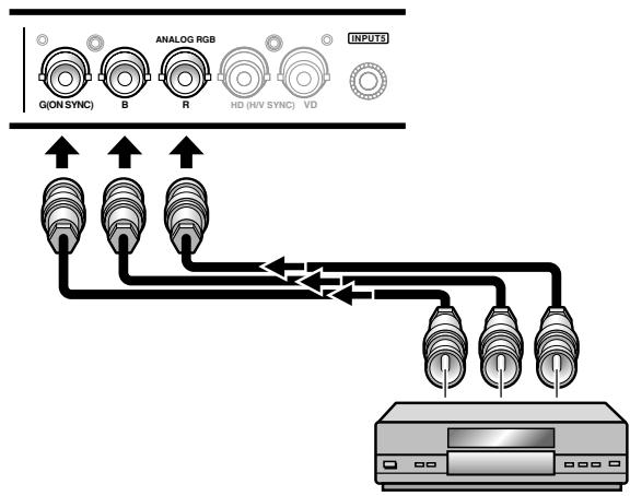
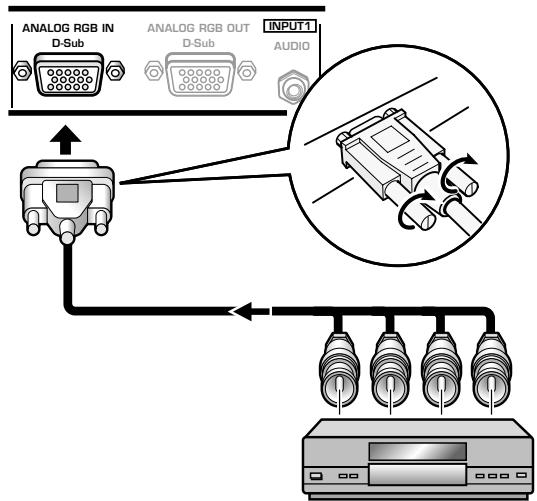
When connecting to COMPONENT VIDEO (INPUT5) — [Connections for PDA-5004]
![PIONEER PDA-5004 - When connecting to COMPONENT VIDEO (INPUT5) — [Connections for PDA-5004] - 1](/content/2025/01/118616/images/00897baf8bb727e5cfe44b514041545c76ffd68f0ae73a42401fcccfef8defc6.jpg)
Connect the G ON SYNC signal to the Y jack, the B signal to the PB / CB jack, and the R signal to the PR / CR jack.
On-screen setup is necessary after connection.
Please see pages 18 to 21.
Connection of composite SYNC analog RGB source
Make composite SYNC connections for a component with output that has the vertical synchronization signal layered on top of the horizontal synchronization signal.
When connecting to ANALOG RGB IN (INPUT1)
On-screen setup is necessary after connection.
Please see pages 18 to 21.
When connecting to ANALOG RGB (INPUT5)
[Connections for PDA-5003]
![PIONEER PDA-5004 - [Connections for PDA-5003] - 1](/content/2025/01/118616/images/735ed924cb2dd60aefb70f87ac2912f79d7e2091a06ccfdd2a2f60079128698e.jpg)
When using INPUT5, set the impedance selector switch to match the output impedance of the connected component's synchronization signal.
When the output impedance of the sync signal is below 75Ω remove the video card and set the impedance selector switch to 75Ω (page 6).
On-screen setup is necessary after connection.
Please see pages 18 to 21.
Note
When making composite SYNC connections, do not connect anything to the VD jack. If connected to, the picture may not be displayed properly.
Connection to a personal computer
Connection method differs depending on the computer type. When connecting, please thoroughly read the computer's operating instructions.
Before making connections, be sure to make sure that the personal computer's power and display's main power is off.
For the PC input signals and screen sizes that the display is compatible with, please refer to the plasma display's Operating Instructions.
Connection of separate SYNC analog RGB source
Make separate SYNC connections for a personal computer that has RGB output separated into 5 output signals: green, blue, red, horizontal synchronization signal, and vertical synchronization signal.
When connecting to ANALOG RGB (INPUT5)
[Connections for PDA-5003]
![PIONEER PDA-5004 - [Connections for PDA-5003] - 1](/content/2025/01/118616/images/fb519f3816bcb8c1bd68dadb40d163f5d95ae923210c764ac86a4f4708c3f348.jpg)
When using INPUT5, set the impedance selector switch to match the output impedance of the connected computer's synchronization signal.
When the output impedance of the sync signal is below 75Ω remove the video card and set the impedance selector switch to 75Ω (page 6).
On-screen setup is necessary after connection.
Please see pages 18 to 21.
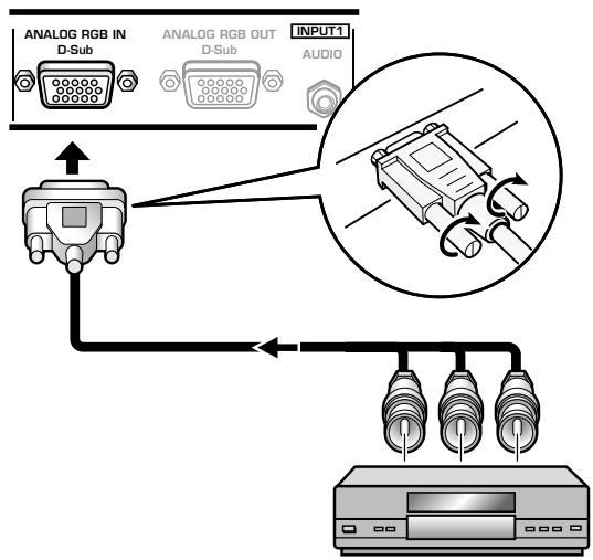
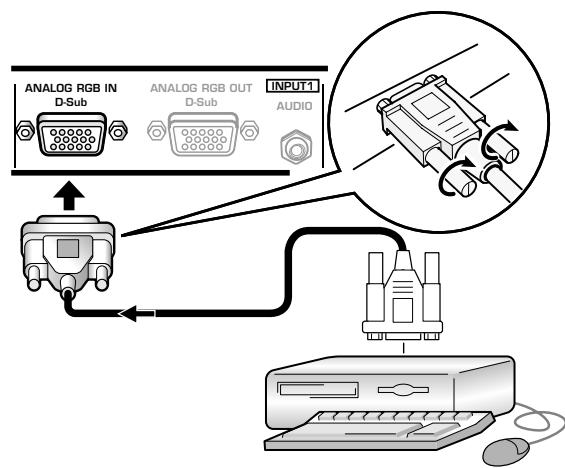
When connecting to ANALOG RGB IN (INPUT1)
Connect the cable corresponding to the shape of the input terminal on the display and the personal computer's output terminal.
Secure by tightening the terminal screws on both units.
On-screen setup is necessary after connection.
Please see pages 18 to 21.
Note
Depending on the type of computer model being connected, a conversion connector or adapter etc. provided with the computer or sold separately may be necessary.
For details, please read your PC's instruction manual or consult the maker or nearest dealer of your computer.
When connecting to ANALOG RGB OUT (INPUT1) —
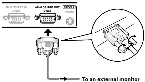
With the plasma display, it is possible to output the video signal to an external monitor or other component from the ANALOG RGB OUT (INPUT1) terminal.
Note
A video signal will not be output from the ANALOG RGB OUT (INPUT1) terminal when the main power of this unit is off or in standby.
Connection of G ON SYNC analog RGB source
Make G ON SYNC connections for a personal computer with output that has the synchronization signal layered on top of the green signal.
When connecting to ANALOG RGB IN (INPUT1)
On-screen setup is necessary after connection.
Please see pages 18 to 21.
When connecting to ANALOG RGB (INPUT5)
[Connections for PDA-5003]
![PIONEER PDA-5004 - [Connections for PDA-5003] - 1](/content/2025/01/118616/images/2ca38cbe8f8a3c47e21bf266074cc07c3ec60f84b73bf1942f3eacdc22fb8db4.jpg)
On-screen setup is necessary after connection.
Please see pages 18 to 21.
Note
When making G ON SYNC connections, do not make any connections to the VD or HD jacks. If connections are made, the picture may be not displayed normally.
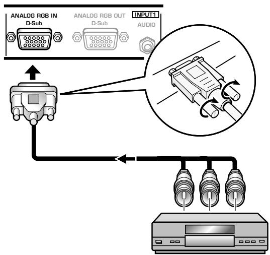
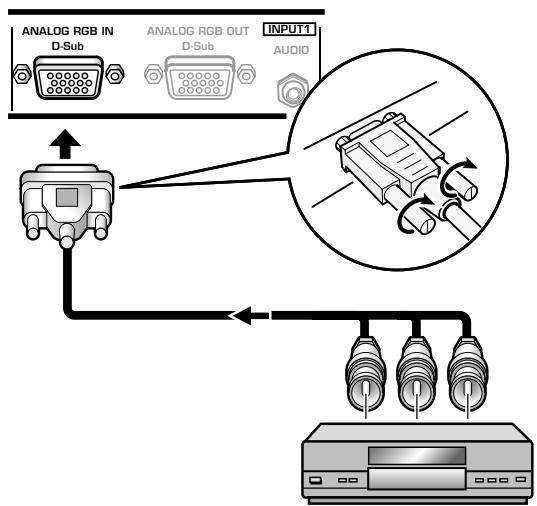
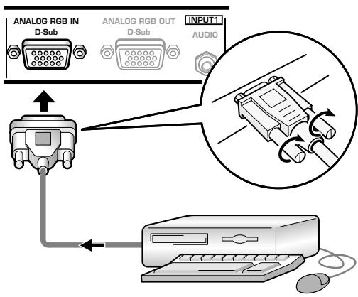
When connecting to COMPONENT Video (INPUT5) — [Connections for PDA-5004]
![PIONEER PDA-5004 - When connecting to COMPONENT Video (INPUT5) — [Connections for PDA-5004] - 1](/content/2025/01/118616/images/3bf94d586edda26fe2817b1c71a3fd177aa489e5e3227ad2b9bc7aa266ed8625.jpg)
On-screen setup is necessary after connection. Please see pages 18 to 21.
Connection of composite SYNC analog RGB source
Make composite SYNC connections for a personal computer with output that has the vertical synchronization signal layered on top of the horizontal synchronization signal.
When connecting to ANALOG RGB IN (INPUT1)
On-screen setup is necessary after connection.
Please see pages 18 to 21.
When connecting to ANALOG RGB (INPUT5)
[Connections for PDA-5003]
![PIONEER PDA-5004 - [Connections for PDA-5003] - 1](/content/2025/01/118616/images/29bcf2996b014c359fa9a435b267d8a44702f853d639a974ce406d31b722f162.jpg)
When using INPUT5, set the impedance selector switch to match the output impedance of the connected computer's synchronization signal.
When the output impedance of the sync signal is below 75Ω remove the video card and set the impedance selector switch to 75Ω (page 6).
On-screen setup is necessary after connection.
Please see pages 18 to 21.
Notes
- When making composite SYNC connections, do not connect anything to the VD jack. If connected to, the picture may not be displayed properly.
- Some types of computer devices manufactured by Apple Computer, Inc. are equipped with both G ON SYNC and composite SYNC outputs. This type of component should be connected using the G ON SYNC connection (page 11).
Connection to INPUT2
A computer equipped with DVI output (digital RGB signal) or an AV component equipped with DVI output (PDP-505CMX/PDP-50MXE10/PDP-50MXE11 only are supported), can be connected to the plasma display's DVI connector (HDCP-compliant).
On-screen setup is necessary after connection.
Please see pages 18 to 21.
Notes
- Use a DVI-D 24-pin (digital only) cable for the connection.
- PDP-504CMX/PDP-50MXE1/PDP-50MXE1-S and PDP-434CMX/PDP-43MXE1/PDP-43MXE1-S do not support the display of copyguard-protected video signals.
NOTICE
- INPUT2 is compatible with Microsoft's Plug & Play (VESA DDC 2B).
- For screen sizes and input signals compatible with INPUT2, please refer to the plasma display's Operation Instructions or Appendix 1 of this Operating Instructions (PDP-505CMX/PDP-50MXE10/PDP-50MXE11 only).
Connection to INPUT3
Connect an AV component that has S-video output jack to the video card's S-VIDEO (INPUT3) jack.
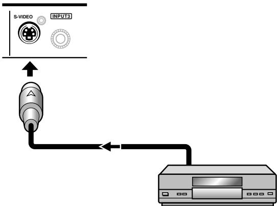
AV component
Connection to INPUT4
Connect an AV component that has a video output jack to the video card's INPUT4 jack. The VIDEO OUT (INPUT4) jack can be used to output the video signal to a separate monitor, recording device or other component with video input capability.
Note
A video signal will not be output from the VIDEO OUT (INPUT4) jack when the main power of this display is off or in standby mode.

[When using PDA-5003]
[When using PDA-5004]
Signals to the INPUT3 and INPUT4 jacks are all compatible with the following TV systems: NTSC, PAL, SECAM, 4.43NTSC, PAL M and PAL N. For details, please refer to "Setting the COLOR SYSTEM" on page 40.
About DTV set top box connection
To ensure proper connection, please carefully read the instruction manual supplied with the DTV set top box.
The set top box output signals that this display is compatible with are as follows.
| Video signal type | Video signal | Video signal format | Jacks where connection is possible | ||||
| INPUT1 | INPUT2* | INPUT3 | INPUT4 | INPUT5 | |||
| HDTV | 1125i (1080i)750p (720p) | Component | ◎ | ◎ | |||
| RGB | ◎ | ◎ | ◎ | ||||
| SDTV | 525i (480i)625i (575i) | Composite | ◎ | ||||
| S Video | ◎ | ||||||
| Component | ◎ | ◎ | |||||
| RGB | ◎ | ◎ | ◎ | ||||
| 525p (480p)625p (575p) | Component | ◎ | ◎ | ||||
| RGB | ◎ | ◎ | ◎ | ||||
- PDP-505CMX/PDP-50MXE10/PDP-50MXE11 only
Audio connections
Before making connections, be sure to check that the audio component's power and the display's main power is off.
Connect an audio component to the audio input jack of the plasma display with installed video card.
When the video card is installed, the plasma display provides four or five audio input jacks and one audio output jack. Consult the following chart to choose the proper audio input for each video input.
| Video input | Audio input | Sound output |
| INPUT1 | Stereo mini jack (L/R) | Sound of the selected video input is output from the SPEAKER (L/R) terminals |
| INPUT2 | Stereo mini jack (L/R) | |
| INPUT5 | Pin jacks (L/R) | |
| INPUT3 | Pin jacks (L/R) *1 | |
| INPUT4 | Pin jacks (L/R) *1 |
*1 When using the PDA-5003, the INPUT3 and INPUT4 audio input connectors are shared.
Audio connection for component connected to INPUT1
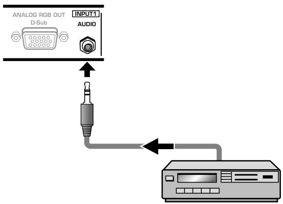
A stereo miniplug cable can be used to connect the audio output from the component connected to INPUT1, to the plasma display's AUDIO (INPUT1) jack (L/R).
Sound is output from both the AUDIO (OUTPUT) stereo mini jack (L/R) and the SPEAKER (L/R) terminals according to the video input selection.
Audio connections for component connected to INPUT2
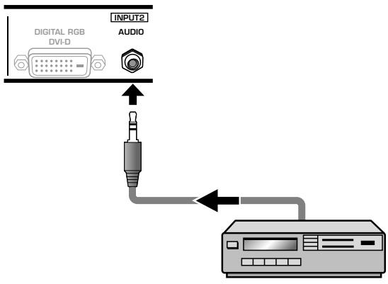
A stereo miniplug cable can be used to connect the audio output from the component connected to INPUT2, to the plasma display's AUDIO (INPUT2) jack (L/R).
Sound is output from both the AUDIO (OUTPUT) stereo mini jack (L/R) and the SPEAKER (L/R) terminals according to the video input selection.
Audio connection for component connected to INPUT5
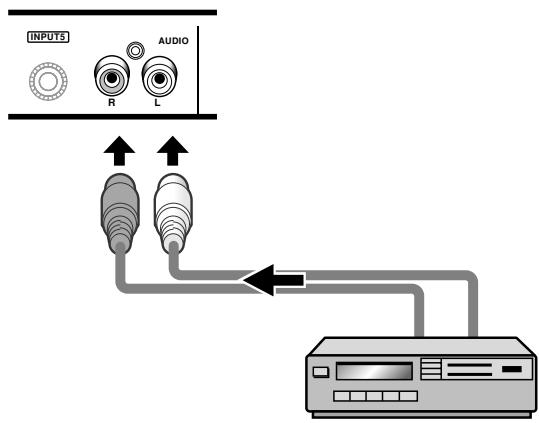
The audio line for the component connected to INPUT5 can be connected to the AUDIO R/L (INPUT5) pin jacks.
Sound is output from both the AUDIO (OUTPUT) stereo mini jack (L/R) and the SPEAKER (L/R) terminals according to the video input selection.
[When using PDA-5003]
Audio connection for component connected to INPUT3 or INPUT4
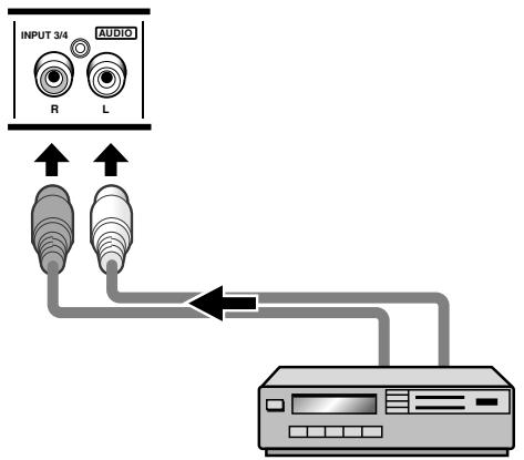
Audio input to the AUDIO R/L (INPUT3/4) pin jacks is possible for a component connected to either INPUT3 or INPUT4.
Sound is output from both the AUDIO (OUTPUT) stereo mini jack (L/R) and the SPEAKER (L/R) terminals according to the video input selection.
[When using PDA-5004]
Audio connection for component connected to INPUT3
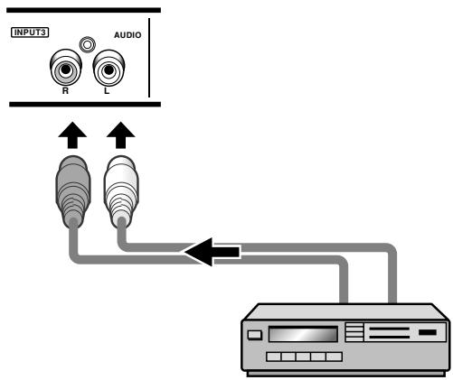
The audio line for the component connected to INPUT3 can be connected to the AUDIO R/L (INPUT3) pin jacks.
Sound is output from both the AUDIO (OUTPUT) stereo mini jack (L/R) and the SPEAKER (L/R) terminals according to the video input selection.
Audio connection for component connected to INPUT4
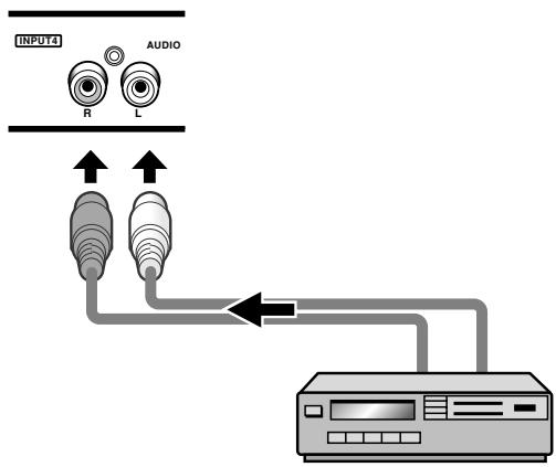
The audio line for the component connected to INPUT4 can be connected to the AUDIO R/L (INPUT4) pin jacks.
Sound is output from both the AUDIO (OUTPUT) stereo mini jack (L/R) and the SPEAKER (L/R) terminals according to the video input selection.
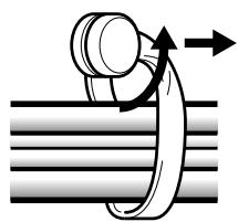
How to route cables
Speed clamps and bead bands are included with the plasma display for bunching cables together. Once components are connected, follow the following steps to route cables.
The illustration depicts the PDP-505CMX/PDP-504CMX/PDP-50MXE10/PDP-50MXE11/PDP-50MXE1/PDP-
50MXE1-S with video card PDA-5003.
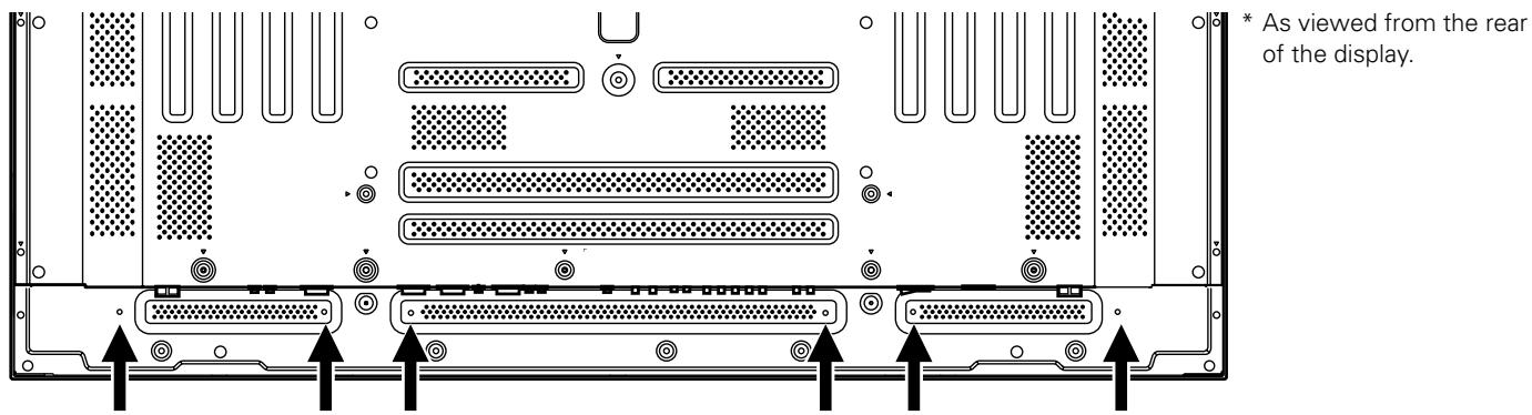
- As viewed from the rear of the display.
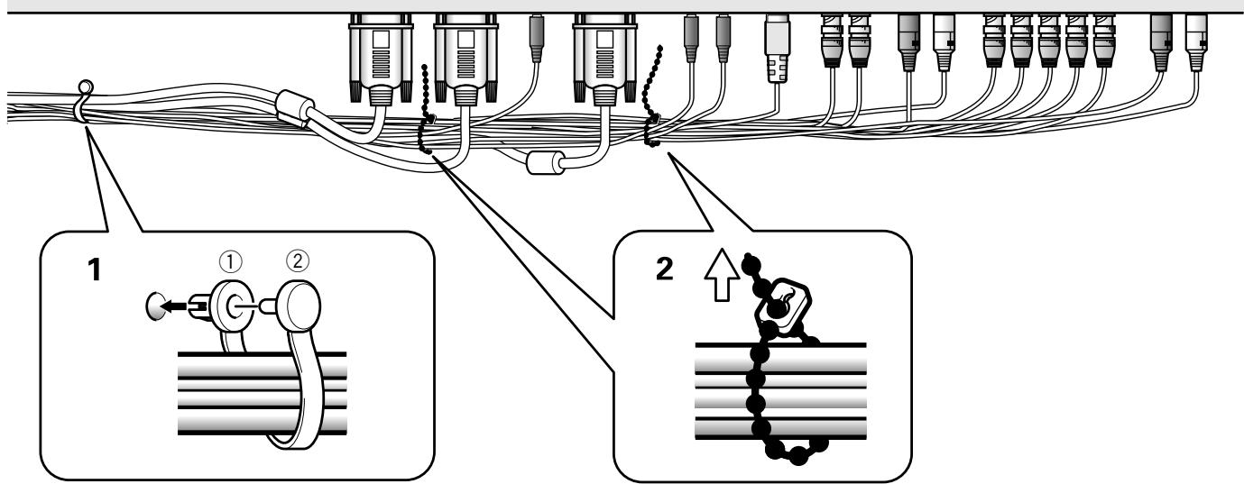
1 Organize cables together using the provided speed clamps.
Insert ① into an appropriate hole on the rear of the unit, then snap ② into the back of ① to fix the clamp.
Speed clamps are designed to be difficult to undo once in place. Please attach carefully.
To attach the speed clamps to the display
Connect the speed clamps using the 6 holes marked with "O" below, depending on the situation.
2 Bunch separated cables together and secure them with the provided bead bands.
Do not allow excessive stress to be placed on the ends of cables.
Note
Cables can be routed to the right or left.
The illustration depicts the PDP-505CMX/PDP-504CMX/PDP-50MXE10/PDP-50MXE11/PDP-50MXE1/PDP-
50MXE1-S with video card PDA-5003.
- As viewed from the rear of the display.
To remove speed clamps
Using pliers, twist the clamp 90irc and pull it outward.
In some cases the clamp may have deteriorated over time and may be damaged when removed.
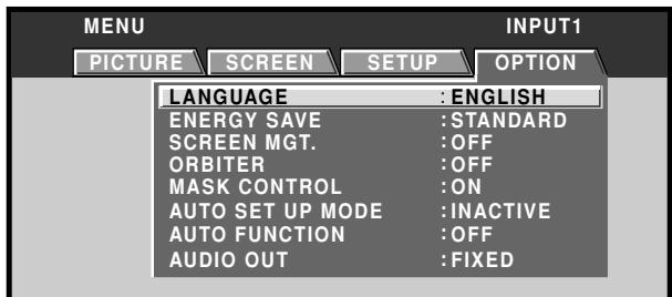
Setting the onscreen display language
The onscreen display language has been set to English as the factory default. To change to another language, the screen setting must be changed. Follow the procedures below to change the setting.

Display operating panel
Remote control unit
1 Set the rear panel MAIN POWER switch to ON.
The STANDBY indicator on the front panel will light red.
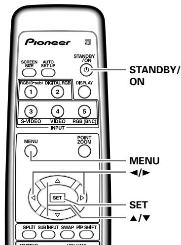
2 Press the STANDBY/ON button to turn the power ON.
The ON indicator on the front panel will light green.
3 Press the MENU button to display the menu screen.

4 Use the / buttons to select [OPTION].
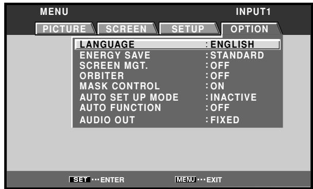
5 Use the / buttons to select [LANGUAGE], then press the SET button.

6 Use the / buttons to select the desired language.
Each time the buttons are pressed, the language alternates between those available, in the following order:
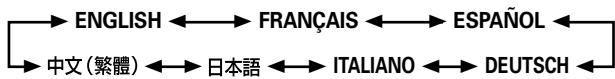

7 With the desired language displayed, press the SET button.
The selected language will be set in memory, and the screen will return to that shown in step 4.
8 When settings are completed, press the MENU button to return to the normal screen image.
Note
When the onscreen display language is set to any of INPUT 1 to INPUT 5, the same display language will be set, regardless of the type of input.
Settings after connections
After components have been connected to INPUT1, INPUT2 or INPUT5, on-screen setup is necessary.
Follow the procedure described below and make settings as they apply to the type of components connected.
[DVI SELECT] setup
(PDP-505CMX/PDP-50MXE10/PDP-50MXE11 only)
Choose the component type (either [PC] or [VIDEO]) that is to be connected to INPUT2.
Display operating panel
Remote control unit
1 Press the MENU button to display the menu screen.
2 Use the / buttons to select [OPTION].
![PIONEER PDA-5004 - Use the / buttons to select [OPTION]. - 1](/content/2025/01/118616/images/06fa64a629d11cc6a66293c22b1a2789d73b09bd77931d325a9cadc7138bc0fd.jpg)
3 Use the / buttons to select [DVI SELECT].
![PIONEER PDA-5004 - Use the / buttons to select [DVI SELECT]. - 1](/content/2025/01/118616/images/f537d6b6bc4387729b759e0cbcd18e4658ad16c3188bd30ebbe6195650343235.jpg)
4 Press the SET button and choose the component to be connected.
The factory default setting is [PC].
Each time the SET button is pressed, the function alternates as shown:
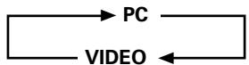
- PC Select when connecting to computer.
VIDEO ...... Select when connecting to AV component.
5 When the setup is completed, press the MENU button to exit the menu screen.
Note
Once settings are complete, turn on or reboot (in the cases of computer) your connected component. If settings have been changed while the connected component is turned on, signals may not be output, or signals may not be output in the correct format.
[ SIGNAL FORMAT ] /
[COLOR DECODING] setup
![PIONEER PDA-5004 - [COLOR DECODING] setup - 1](/content/2025/01/118616/images/f04db0aefbde3abe90fc1ce9b85e706f932cb0f8bc6fd95b8936c603ae5b3116.jpg)
Display operating panel
![PIONEER PDA-5004 - [COLOR DECODING] setup - 2](/content/2025/01/118616/images/eb658b14038b92d1732c7f93ed8c97efb70d549bb58660150b49637649f0e876.jpg)
Remote control unit
1 Select INPUT1, INPUT2 or INPUT5.
2 Press the MENU button to display the menu screen.
![PIONEER PDA-5004 - [COLOR DECODING] setup - 3](/content/2025/01/118616/images/1d98432ee604fa5083546455e652a8ad682cfbfa395bef4e7a2017e0e3a8b9fd.jpg)
3 Use the / buttons to select [SETUP].
![PIONEER PDA-5004 - [COLOR DECODING] setup - 4](/content/2025/01/118616/images/f558c7054d9ec77f5b9bf62896f206ef13d14b08be190dea0402fc34fe9425d5.jpg)
4 Use the / buttons to select [SIGNAL FORMAT], then press the SET button.
![PIONEER PDA-5004 - [COLOR DECODING] setup - 5](/content/2025/01/118616/images/dba2a085ddb0dbe3ea0b71bbe249e5bee278a2ebb83544f0577865bbfeff8825.jpg)
5 Use the / buttons to select the display mode.
![PIONEER PDA-5004 - [COLOR DECODING] setup - 6](/content/2025/01/118616/images/d0f76c1a31dd6f97560e3857d037aa07d602a281552db32ae4f1356693fd0246.jpg)
① When the input signal has a refresh rate of 31.5kHz horizontal / 60 Hz vertical, pressing will cause the display mode to change alternately as follows: When using INPUT1, INPUT5 or INPUT2 (PDP-505CMX/PDP-50MXE10/PDP-50MXE11 only):
![PIONEER PDA-5004 - [COLOR DECODING] setup - 7](/content/2025/01/118616/images/db6ec3085aa4948ebc1084b57a8a7a4c25b632aef36a68268afbf75b3ea723cd.jpg)
When using INPUT2 (PDP-504CMX/PDP-50MXE1/ PDP-50MXE1-S and PDP-434MCX/PDP-43MXE1/ PDP-43MXE1-S only):
![PIONEER PDA-5004 - [COLOR DECODING] setup - 8](/content/2025/01/118616/images/c4a327b80fe01716be83053a2eb17313c6a80914437a4b3cfddf30dc5637b7ec.jpg)
② When providing input signals with refresh rates of 45 kHz horizontal/60 Hz Vertical, pressing the buttons causes the display mode to alternate as follows:
![PIONEER PDA-5004 - [COLOR DECODING] setup - 9](/content/2025/01/118616/images/6e6942622a65ac30cdfffabc84552292e2cc593f7a66c1fdff18142d757efd7c.jpg)
[720-PC] indicates resolution of 1280 × 720 .
③ When the input signal has a refresh rate of 48.4 kHz horizontal / 60 Hz vertical, or 56.1 kHz horizontal / 70 Hz vertical, pressing will cause the display mode to change alternately as follows:
![PIONEER PDA-5004 - [COLOR DECODING] setup - 10](/content/2025/01/118616/images/e2dcf28be0369754ae0198d5a08e892923078af9701363a8a857576eeb41eaa1.jpg)
If the [PC AUTO] setting is selected, screen resolution will automatically switch between [XGA] and [WXGA] as required.
④ When the input signal has a refresh rate of 64kHz horizontal / 60 Hz vertical, 80 kHz horizontal / 75 Hz vertical, or 91.2 kHz horizontal / 85 Hz vertical, pressing ← will cause the display mode to change alternately as follows:
![PIONEER PDA-5004 - [COLOR DECODING] setup - 11](/content/2025/01/118616/images/c339843b8db450ebc26532fbfa5fb04fb1a9971b681330c8aff8d3c58ee2d8a1.jpg)
Notes
- These settings are required only when providing input signals with the following refresh rates: ① 31.5kHz horizontal / 60 Hz; ② 45kHz horizontal / 60 Hz vertical; ③ 48.4kHz horizontal / 60 Hz vertical or 56.1kHz horizontal / 70 Hz vertical; ④ 64kHz horizontal / 60 Hz vertical; 80kHz horizontal / 75 Hz vertical or 91.2kHz horizontal / 85 Hz vertical. Adjustment for other signal frequency formats is performed automatically, so no manual setting is required (the [SIGNAL FORMAT] message does not appear).
- The [PC AUTO] setting supports automatic signal selection only when using RGB separate SYNC inputs.
- When G ON SYNC or Composite SYNC signals are input, selecting [PC AUTO] will cause the screen resolution to be set to [XGA] only.
- When using G ON SYNC or Composite SYNC with WXGA inputs, set [SIGNAL FORMAT] manually to [WXGA].
6 Press the SET button.
The setting is stored in memory and the screen returns to that shown in step 4.
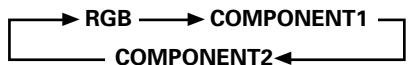
7 When a component other than a computer is connected, use the / buttons to select [COLOR DECODING] (INPUT1, INPUT2 or INPUT5).
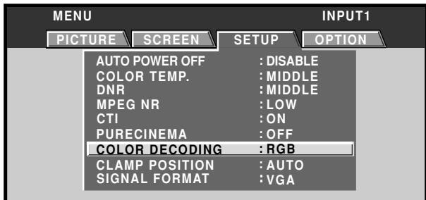
8 Press the SET button repeatedly to select the input signal format.
Selection will change as follows each time the SET button is pressed:
The table below shows what settings are appropriate and available for the type of connections made.
Set [SIGNAL FORMAT] and [COLOR DECODING] as follows. Please take care when making settings. Incorrect settings can adversely affect the plasma display.
| SETUP Connected component | SIGNAL FORMAT | COLOR DECODING |
| Component video output of a DVD player, etc. | 525p | COMPONENT1 |
| Component video output from digital tuner, etc. | 750p | COMPONENT2 |
| RGB video output of a video deck etc., with RGB output | 525p | RGB |
| DVI video output of an AV component with DVI output port (PDP-505CMX/PDP-50MXE10/PDP-50MXE11 only) | 525p, 750p | RGB |
| RGB video output of a PC | VGA, WVGA, 720-PC, XGA, WXGA, SXGA, SXGA+ | Not supported |
9 When the setup is completed, press MENU to exit the menu screen.
Notes
- Set [SIGNAL FORMAT] and [COLOR DECODING] for each applicable input (INPUT1, INPUT2 or INPUT5).
- The [COLOR DECODING] setting is not supported when inputting a computer signal, or when the [SIGNAL FORMAT] function has been used to select a signal other than [525p] or [750p].
[CLAMP POSITION] setup
Depending on the signal, analog RGB signals may result in the screen image appearing with a whitish or greenish cast. In such cases, set [CLAMP POSITION] to [LOCKED]. Normally, leave this setting at [AUTO].
![PIONEER PDA-5004 - [CLAMP POSITION] setup - 1](/content/2025/01/118616/images/1c3559ad74baceaff2bdcd46f4607854e4067d5cc3cb698a383b9c6f6ce85ff4.jpg)
Display operating panel
![PIONEER PDA-5004 - [CLAMP POSITION] setup - 2](/content/2025/01/118616/images/6284ca74765d5b7dbc63ebbf70d908c5d2c2c9def9fda53d07dc5ccadd89e269.jpg)
Remote control unit
1 Press the MENU button to display the menu screen.
2 Use the / buttons to select [SETUP].
![PIONEER PDA-5004 - Use the / buttons to select [SETUP]. - 1](/content/2025/01/118616/images/7358451e96fe3d25ba0f3a233cd5c2d67140d71da493ecf0e890d2dc836f5d45.jpg)
3 Use the / buttons to select [CLAMP POSITION].
![PIONEER PDA-5004 - Use the / buttons to select [CLAMP POSITION]. - 1](/content/2025/01/118616/images/cd58dfc32caf18c96d27320a370d92187125a51f924eb7635d4974bafc7935d8.jpg)
4 Press the SET button to select [LOCKED].
![PIONEER PDA-5004 - Press the SET button to select [LOCKED]. - 1](/content/2025/01/118616/images/86ee31bac6f22eaa8de505fff83c02d673221d826be9f484ac92124ababad0a8.jpg)
The factory default setting is [AUTO]. Mode selection will change as follows each time the SET button is pressed:
![PIONEER PDA-5004 - Press the SET button to select [LOCKED]. - 2](/content/2025/01/118616/images/b30f508e45f9e38c0f2ee89826f00318082f0f3a306213f16fd1bcaea758d0ce.jpg)
5 When the setup is completed, press the MENU button to exit the menu screen.
Notes
- Make this [CLAMP POSITION] setting for each applicable input (PDA-5003: INPUT1 or INPUT5, PDA-5004: INPUT1).
- When using this setup, be sure to carefully check the signal output of the component that you are using. For details, please refer to the instruction manual supplied with the component you are connecting.
Selecting input source
This section explains the basic operation of the plasma display. Outlined on the following pages is how to turn the main power on and off, put this display in the operation or standby mode and how to select connected components.
Before you begin, make sure you have:
- Made connections between the plasma display and AV components or personal computer as described in the section "Installation and Connections" starting on page 6.
- Set up the on-screen menu to input signals from components connected to INPUT1, INPUT2 and INPUT5 as described in the section "System Settings" starting on page 18.
If no connections are made to these terminals, on-screen setup is not necessary.
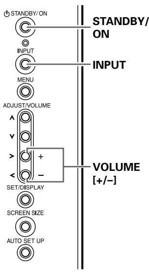
Display operating panel
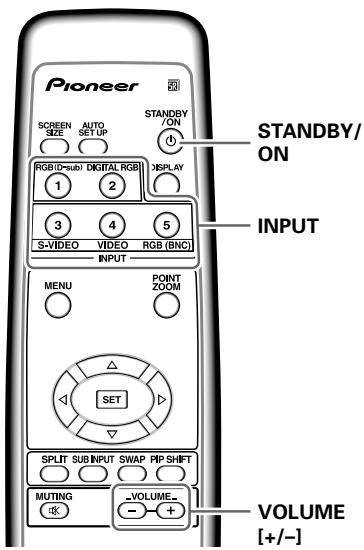
Remote control unit
1 Set the rear panel MAIN POWER switch to ON.
The STANDBY indicator on the front panel will light red.
2 Press the STANDBY/ON button to turn the power ON.
The ON indicator on the front panel will light green.
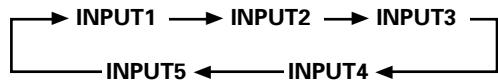
3 Press the INPUT button on the remote control unit or the display to select the input.
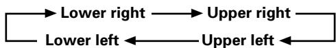
Input changes each time the display's INPUT button is pressed as follows:
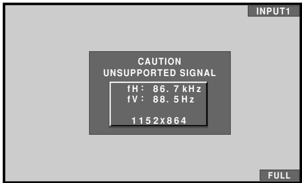
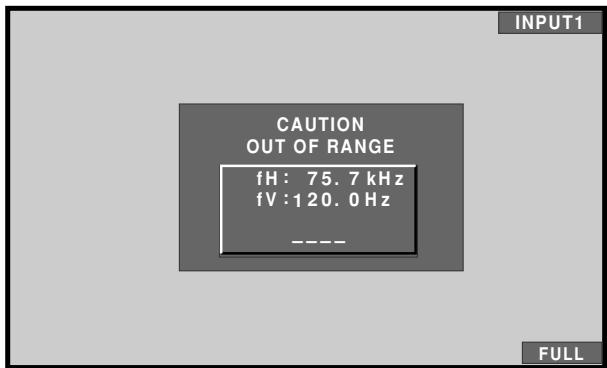
- When the menu screen is displayed, changing the signal input will cause the menu screen to turn off.
- If the input computer signal is not supported by the display, the following message will be displayed:
4 Use VOLUME (+ / - ) buttons on the remote control unit or the display to adjust the sound volume.
If no audio connections are made to the plasma display, this step is not necessary.
5 When viewing is finished, press the STANDBY/ON button to put the display in standby mode.
6 Set the rear panel MAIN POWER switch to OFF.
The STANDBY indicator may continue to light for a short while even after the main power is turned off. This is a result of residual electric load impressed on the circuitry, and the light will turn off presently.
Note
Please do not leave the same picture displayed on the screen for a long time. Doing so may cause a phenomenon known as "screen burn" which leaves a ghost, or residual, image of the picture on the screen.
Adjusting sound volume
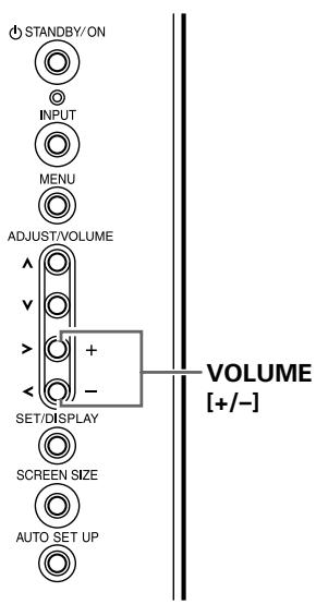
Display operating panel
Remote control unit
Press the VOLUME buttons.
Press the [-] or [+] button to respectively decrease and increase the volume of sound from the speakers.

Muting the sound
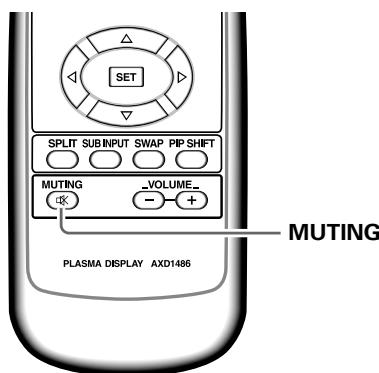
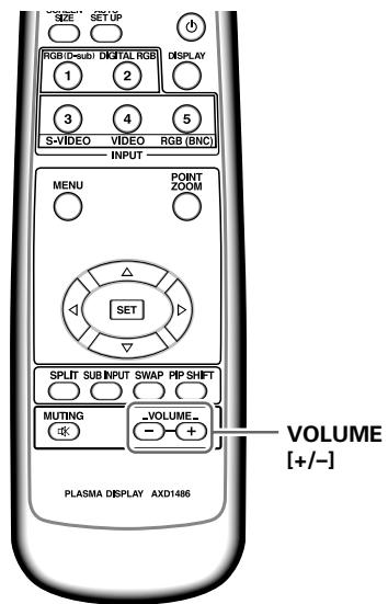
Press the MUTING button on the remote control unit.
Press the MUTING button again to restore the sound.
Muting is automatically canceled about 8 minutes after the button is pressed, and the volume level is adjusted to the minimum level.
Press VOLUME + or VOLUME - to adjust the volume at a desired level.
Confirming current status
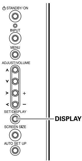
Display operating panel
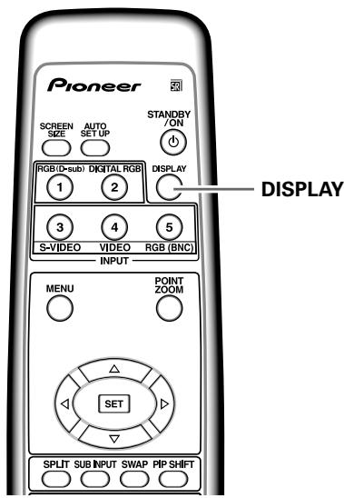
Remote control unit
Press the DISPLAY button.
The currently selected input, screen size and refresh rates will be displayed for about 3 seconds.
Notes
The displayed refresh rates may be slightly different from actual values.
- When using the Point zoom function (page 25) or Multiscreen function (page 26), the position and input information for the enlarged screen area will be displayed.
- When the screen management function is active, the [SCREEN MGT.] message will also be displayed at the lower left corner of the screen.
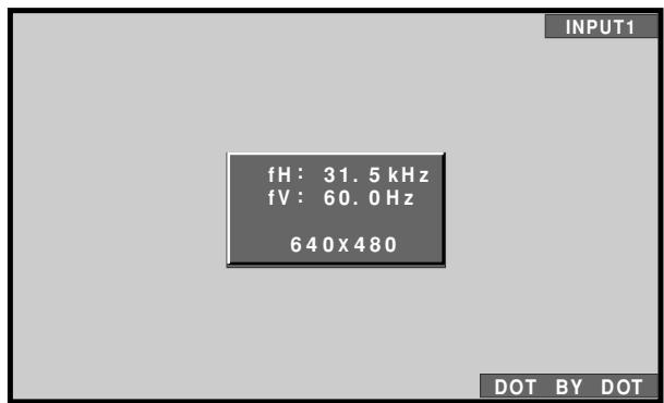
Changing screen size
The plasma display incorporates screen modes of various height and width ratios. For optimal viewing, we recommend that you select the screen mode that best matches the video source that you are viewing. Although these modes are designed for full display of a picture on a wide screen, it is our hope that you make use of them with a full understanding of the manufacturer's intentions.
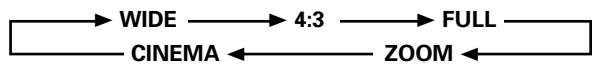
Screen size selection
For video signals
The size of the picture or the picture's range projected on the screen can be changed between 5 screen sizes described in the table on this page.
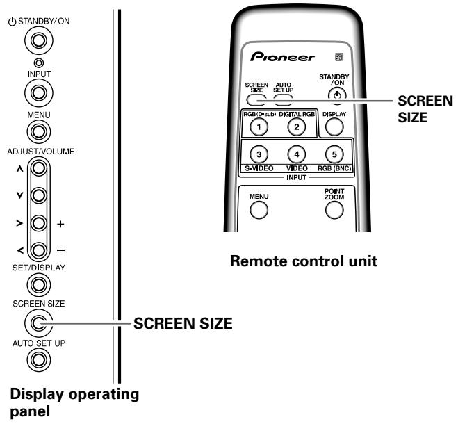
Press the SCREEN SIZE button to select the size.
The screen size changes each time the SCREEN SIZE button is pressed as follows:
- The screen modes selectable may differ on INPUT1, INPUT2 (PDP-505CMX/PDP-50MXE10/PDP-50MXE11 only) and INPUT5, depending on the type of signal input. For details, consult the "Appendix 1: Video signal compatibility table" (page 44).
Notes
- When the [WIDE], [ZOOM], or [FULL] setting is used to display a non-wide screen 4:3 picture fully on a wide screen, a portion of the picture may be cut off or appear deformed.
- Be aware that when the display is used for commercial or public viewing purposes, selecting the [WIDE], [ZOOM], [CINEMA] or [FULL] mode settings may violate the rights of authors protected under copyright law.
- When [4:3] screen size is selected, the display position is moved slightly each time the power is turned on, in order to prevent image burning.
During video signal input
| How the picture looks | |
| WIDE | Suitable for when viewing news or sports programs. Movies or sports programs can be viewed with an expansive powerful image. |
| 4:3 | Suitable for when viewing news or sit coms. The video software can be viewed in its original screen frame size. |
| FULL | Suitable for wide screen images (squeeze). |
| ZOOM | Mainly suitable for viewing Cinemascope size and other such movie images. Provides a more expansive, powerful image. |
| CINEMA | Primarily suitable for viewing "Vista vision" cinema sizes. |
Consult the plasma display's Operating Instructions regarding the screen size during computer signal input.
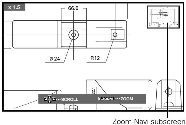
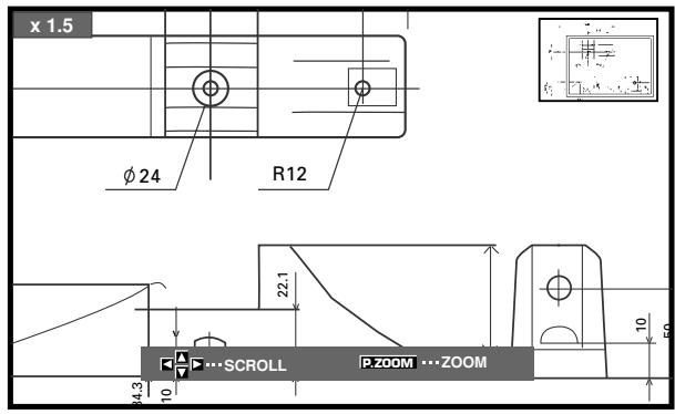
Enlarging one part of the screen (POINT ZOOM)
This plasma display allows enlarging of the screen image by ratios of [x 1.5], [x 2], and [x 3]. When enlarging the screen, the / / buttons can be used to move the enlarged viewing area around the screen.
- The range of zoom possible can be confirmed by viewing the Zoom-Navi subscreen at the upper right of the main screen. The Zoom-Navi subscreen is displayed for about three seconds whenever the POINT ZOOM button, one of the / / buttons, or DISPLAY button is pressed.
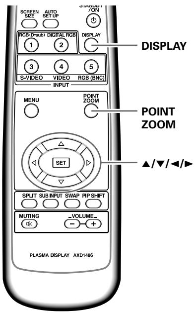
1 Press the remote control unit's POINT ZOOM button.
Each time the POINT ZOOM button is pressed, the zoom ratio alternates in the following order:

Note
During use of the POINT ZOOM function, the screen size cannot be changed.
2 Using the / / buttons, move the screen to the desired part of the image.
- Pressing the POINT ZOOM and / / buttons again will change the zoom ratio and the position of screen enlarged.
- If the input signal changes, or if the menu screen is displayed and the input is changed, or if the multiscreen mode is selected, the POINT ZOOM function will be canceled.
Note
Be aware that when the display is used for commercial or public viewing purposes, selecting the [WIDE], [ZOOM], [CINEMA] or [FULL] mode settings may violate the rights of authors protected under copyright law.
Multiscreen display
The plasma display's multiscreen function allows the simultaneous display of two inputs. The multiscreen display include three modes, 2-SCREEN, PinP, and PoutP.
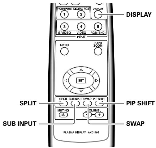
1 Press the remote control unit's SPLIT button.
Each time the button is pressed the multiscreen display changes in the following order:
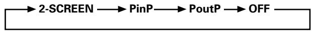
① 2-SCREEN
The main screen is displayed on the left and the subscreen on the right.
② PinP
The subscreen is displayed in one of the four corners of the main screen.
③ PoutP
The subscreen is displayed outside the right side of the main screen.
2 Press the remote control unit's SUB INPUT button to select the subscreen input source.
To exchange the main screen and subscreen inputs
Press the remote control unit's SWAP button.
- When 2-SCREEN mode has been selected:
The right and left sides of the display will switch; what was previously the main screen will now show the subscreen, and vice versa.
- When PinP or PoutP has been selected:
What was previously the main screen image will now appear in reduced size as the subscreen image, and vice versa.
To change the position of the subscreen in PinP mode:
Press the remote control unit's PIP SHIFT.
Each time the button is pressed, the position of the subscreen moves in the following order:
To display the currently selected input Press the DISPLAY button.
If the DISPLAY button is pressed while in multiscreen mode, the main screen and sub-screen will each be displayed with its currently selected input.
Notes
- When using the plasma display in a profit-making activity, or when exhibiting images publicly, using the screen size function to compress or stretch the image may result in infringement of the copyrights of the image owners.
- If the multiscreen display is left on for an extended period of time, or if the same multiscreen display is repeatedly shown for short periods on an everyday basis, a residual image pattern may be burned onto the screen.
- When selecting the 2-SCREEN mode, the screen image may appear somewhat rougher, depending on the source used.
- The multiscreen mode will be canceled if a menu is opened, or if POINT ZOOM is performed.
- The screen size cannot be changed during multiscreen display.
- The sound of the input selected in the main screen is outputted when using the multiscreen function.
Automatic power-off (POWER MANAGEMENT)
The plasma display is equipped with [POWER MANAGEMENT] and [AUTO POWER OFF] functions; when set, the function automatically switches the unit to either standby mode or power off mode whenever a sync signal is not detected (a warning message is displayed on the screen before the functions operate).
Notes
- [POWER MANAGEMENT] settings are supported only when a computer signal is input to INPUT1, INPUT2 or INPUT5 (PDA-5003 only).
- The auto-power-off function can be used only in those cases other than the inputs used in the preceding item.
- Always turn off the plasma display's main power switch when not using the display for extended periods of time.
Display operating panel
Remote control unit
1 Press the MENU button to display the menu screen.
2 Use the / buttons to select [SETUP]. [When computer signal is input to INPUT1, INPUT2 or INPUT5 (PDA-5003 only)]
![PIONEER PDA-5004 - Use the / buttons to select [SETUP]. [When computer signal is input to INPUT1, INPUT2 or INPUT5 (PDA-5003 only)] - 1](/content/2025/01/118616/images/fe7cf5eb33b6afd2048076303524845cf001786b113dcba30835d6c9749fa8ce.jpg)
[In all other cases]
![PIONEER PDA-5004 - [In all other cases] - 1](/content/2025/01/118616/images/0fba2e414a28b7ff8b3b39e7d7d82b51a9a928e68188dea2bfeca0533340f180.jpg)
3 Press the SET button to confirm selection of the [POWER MANAGEMENT] or [AUTO POWER OFF].
The factory default setting is [OFF/DISABLE].
Each time the button is pressed, the setting alternates as follows:
![PIONEER PDA-5004 - Press the SET button to confirm selection of the [POWER MANAGEMENT] or [AUTO POWER OFF]. - 1](/content/2025/01/118616/images/fbe535a47b82fb12c2f91d3a58328080ff11239f0670cb8e7344783030ec2f05.jpg)
- OFF/DISABLE......
The display will continue in operating mode, regardless of the presence/absence of an input sync signal.
- POWER MANAGEMENT: ON......
If a sync signal is not detected, a warning message is first displayed for 8 seconds, after which the display automatically enters the standby mode, and the ON indicator flashes green. If a sync signal (*1) is input again later, the plasma display automatically returns to normal operating mode.
*1 Except when input signal is G ON SYNC or composite SYNC.
- AUTO POWER OFF: ENABLE......
If no sync signal is detected for 8 minutes or more, a warning message will be displayed for 30 seconds, after which the display's power will switch to power off mode.
4 When the setup is finished, press the MENU button to exit the menu screen.
Note
The [POWER MANAGEMENT] and [AUTO POWER OFF] functions must be set individually for each input (INPUT1 to INPUT5).
To return to operating mode:
- To return to normal operation from the [POWER MANAGEMENT] function's standby mode, either operate your computer, or press the INPUT button on the plasma display or remote control unit.
- To return to normal operation from the [AUTO POWER OFF] function's power off condition, press the STANDBY/ON button on the plasma display or on the remote control unit.
PICTURE adjustment
1 Press the MENU button to display the menu screen.

2 Use the / buttons to select the adjustment item, then press the SET button.
3 Use the / buttons to adjust the picture quality as desired.

4 Press the SET button.
Pressing the SET button writes the value into the memory and returns the display to the step 2 screen.
5 When the setup is finished, press the MENU button to exit the menu screen.
Note
Make these adjustments for each input (INPUT1 to INPUT5) and signals.
[PICTURE] mode adjustment items
Below are brief descriptions of the options that can be set in the [PICTURE] mode.
CONTRAST Adjust according to the surrounding brightness so that the picture can be seen clearly.
BRIGHTNESS Adjust so that the dark parts of the picture can be seen clearly.
COLOR Adjust to the desired depth (Setting to a slightly deep color will create a natural looking picture).
TINT Adjust so that flesh tones look normal.
SHARPNESS Normally set to the center position. To create a softer picture, set to the left of center. To create a sharper picture, set to the right of center.
Note
Consult the Operating Instructions for your Plasma Display regarding PICTURE adjustment when inputting computer signals.
To reset [PICTURE] mode settings to the default
If settings have been adjusted excessively or the picture on the screen no longer appears natural, it may prove more beneficial to reset the [PICTURE] mode to default settings instead of trying to make adjustments under already adjusted conditions.
1 In step 2 in the previous procedure, use the / buttons to select [PICTURE RESET], then press the SET button.
![PIONEER PDA-5004 - To reset [PICTURE] mode settings to the default - 1](/content/2025/01/118616/images/de19a480ca7f6ec933987a3f7d33e997db07cf898a0cda4abf0e703ebf6895ac.jpg)
2 Use the / buttons to select [YES], and press the SET button.
All [PICTURE] mode settings are returned to the factory set default.
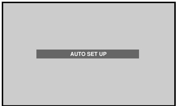
Adjusting screen POSITION, CLOCK, and PHASE
By pressing the AUTO SET UP button on either remote control unit or the plasma display's operating panel (or by selecting [AUTO SET UP MODE] from the menu), the unit will automatically set the screen position and clock to best match the current image input.
When the button is pressed, the optimum settings are automatically selected for the current input source.
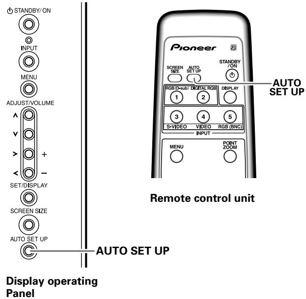
Press the AUTO SET UP button on either the display or remote control unit.
Notes
- This setting is supported only when a computer signal is connected to INPUT1 or INPUT5.
- Perform this adjustment individually for each input function (INPUT1 or INPUT5), and each signal type.
- Optimum settings may not be possible for low-luminance and certain other signals. In such cases, use the adjustment methods explained on the next page, "Adjusting screen POSITION, CLOCK, and PHASE
".
When the automatic setup mode is selected, the unit will automatically be adjusted to the optimum image settings whenever the power is turned on, the input source is changed, or the type of input signal is changed.
Display operating panel
Remote control unit
1 Press the MENU button to display the menu screen.

2 Use the / buttons to select [OPTION].
![PIONEER PDA-5004 - Use the / buttons to select [OPTION]. - 1](/content/2025/01/118616/images/19451f6efe49a52600bf1d844e8c4b0bf89fa38375df953389224c80fc01e08f.jpg)
3 Use the / buttons to select [AUTO SET UP MODE].
![PIONEER PDA-5004 - Use the / buttons to select [AUTO SET UP MODE]. - 1](/content/2025/01/118616/images/4783f49d5c4ac7cbda72d3daaf7d5490202d93f3f968a6a738bcc70c6b462d81.jpg)
4 Press the SET button to activate the setting.
The factory default setting is [INACTIVE].
Each time the button is pressed, the setting alternates
as follows:
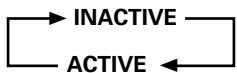
5 When finished with the setting, press the MENU button to return to the normal screen image.
Notes
- This setting is supported only when a computer signal is connected to INPUT1 or INPUT5.
- Optimum settings may not be possible for low-luminance and certain other signals. In such cases, set the [AUTO SETUP MODE] to [INACTIVE], and use the manual adjustment methods explained in the following section, "Adjusting screen POSITION, CLOCK, and PHASE
"
Adjusting screen POSITION, CLOCK, and PHASE
This setting can be adjusted when a computer signal is connected to INPUT1, INPUT2, or INPUT5.
Display operating panel
Remote control unit
1 Press the MENU button to display the menu screen.

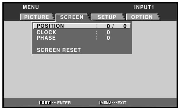
2 Use the buttons to select [SCREEN].
![PIONEER PDA-5004 - Use the buttons to select [SCREEN]. - 1](/content/2025/01/118616/images/aeacd24584fbb2421b18f90373ef109ce3e201edf6105071ef1710edb0c12b29.jpg)
INPUT2, 3 or 4 is selected, the following screen will appear and the [POSITION] adjustment only can be selected.
![PIONEER PDA-5004 - Use the buttons to select [SCREEN]. - 2](/content/2025/01/118616/images/1bc0972296bcae9dd4001a91c63ad285843b369dbe7d92b6915f77806756c668.jpg)
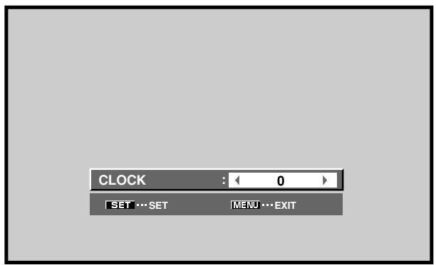
3 Use the / buttons to select the adjustment item, then press the SET button.
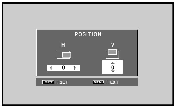
4 Use the / and / buttons to select the desired value.
- When the [POSITION] item is selected, the buttons control movement in the Horizontal direction (H), and the buttons control movement in the Vertical direction (V).
- Use the buttons for the adjustments of [CLOCK] and [PHASE].
5 Press the SET button.
Pressing the SET button writes the value into the memory and returns the display to the step 3 screen.
6 When adjustment is finished, press the MENU button to exit the menu screen.
Notes
- Make these adjustments for each input (INPUT1 or INPUT5) and signals.
- If INPUT2 is selected, only the [POSITION] can be adjusted.
[SCREEN] mode adjustment items
Below are brief descriptions of the options that can be set in the [SCREEN] mode.
POSITION
H Adjust the picture's position to the left or right.
V Adjust the picture's position upward or downward.
CLOCK Adjust letter breakup or noise on the screen. This setting adjusts the display's internal clock signal frequency that corresponds to the input video signal.
PHASE Adjust so that there is minimum flicker of screen letters or color misalignment. This setting adjusts the phase of the internal clock signal adjusted by the [CLOCK] setting.
Notes
- The [CLOCK] and [PHASE] adjustment items are supported only for INPUT1 and INPUT5.
- When the [CLOCK] frequency is changed, the [POSITION] command's horizontal [H] option may require readjustment.
- If the adjustment items in the [SCREEN] mode are adjusted excessively, the picture may not be displayed properly.
- When the [AUTO SET UP MODE] set to [ACTIVE], selecting the [POSITION] and [CLOCK] adjust modes will cause a message to be displayed on the screen, but adjustment is possible. However, if the input source is changed, the adjustment value stored in memory will be the one automatically set with the auto setup mode. If you wish to record a manually set adjustment value, set the [AUTO SET UP MODE] to [INACTIVE] (page 29) before beginning your adjustments.
To reset [SCREEN] mode settings to the default If settings have been adjusted excessively or the picture on the screen no longer appears natural, it may prove more beneficial to reset the [SCREEN] mode to default settings instead of trying to make adjustments under already adjusted conditions.
1 In step 3 in the previous procedure, use the / buttons to select [SCREEN RESET], then press the SET button.
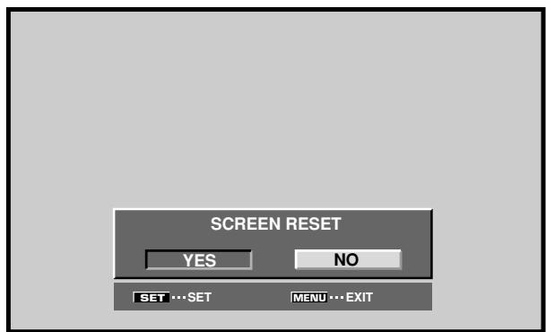
2 Use the / buttons to select [YES], and press the SET button.
All [SCREEN] mode settings are returned to the factory set default.
Setting the orbiter (ORBITER)
At set time intervals (about once every 8 minutes), this function automatically changes the screen display position by incremental amounts. The amount of screen movement is 1 pixel horizontally or vertically.
When displaying a still image, setting [ORBITER] to [ON] helps prevent the screen from being burnt with a lag image.
- This function is not supported when using the POINT ZOOM function, multiscreen function, or menu display.
Display operating panel
Remote control unit
1 Press the MENU button to display the menu screen.
2 Use the / buttons to select [OPTION].
3 Use the / buttons to select [ORBITER].
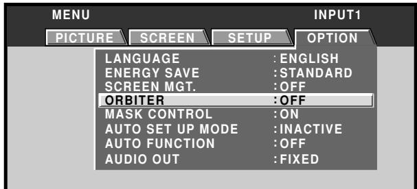
4 Press the SET button to activate the setting.
The factory default setting is [OFF].
Each time the button is pressed, the setting alternates as follows:

5 When finished with the setting, press the MENU button to return to the normal screen image.
Note
The [ORBITER] setting affects all input sources.
Side mask position (MASK CONTROL)
When screen size is set to [DOT BY DOT] or [4:3], or when using multiscreen display, the position of the black stripes on the side of the screen and the position of the subscreen are changed slightly each time the power is turned on, in order to alleviate burning of lag images on the screen.
Display operating panel
Remote control unit
1 Press the MENU button to display the menu screen.
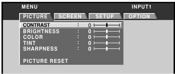
2 Use the / buttons to select [OPTION].
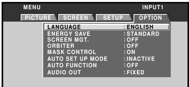
3 Use the / buttons to select [MASK CONTROL].
![PIONEER PDA-5004 - Use the / buttons to select [MASK CONTROL]. - 1](/content/2025/01/118616/images/b687d23a79a15fdea5d2bca6a46f9ca6d1e9667b7495a9d962bde607f1879d7b.jpg)
4 Press the SET button to activate the setting.
The factory default setting is [ON].
Each time the button is pressed, the setting alternates
as follows:
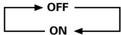
5 When finished with the setting, press the MENU button to return to the normal screen image.
Note
The [MASK CONTROL] setting affects all input sources.
Screen management settings (SCREEN MGT.)
In order to alleviate burning of lag images in the screen, this plasma display is equipped with a screen management program that allows automatic switching of the display image at regular intervals. The program can be set to determine how the 24-hour screen management cycle is repeated.
For information about detailed screen management settings, consult your professional installation technician.
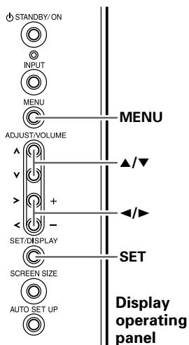
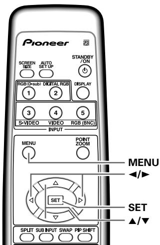
Remote control unit
1 Press the MENU button to display the menu screen.
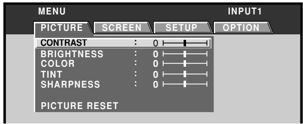
2 Use the buttons to select [OPTION].
![PIONEER PDA-5004 - Use the buttons to select [OPTION]. - 1](/content/2025/01/118616/images/f08d0ddd5d4144a4cde0079318b25bc09a7d989b81667bbe5065db9f96778984.jpg)
3 Use the / buttons to select [SCREEN MGT.], then press the SET button.
![PIONEER PDA-5004 - Use the / buttons to select [SCREEN MGT.], then press the SET button. - 1](/content/2025/01/118616/images/33cd7041c3ed45e26613f2ea164298e18c0d674e37983ffa930d908b8d2e9a6a.jpg)
4 Use the / buttons to select [STATUS].
![PIONEER PDA-5004 - Use the / buttons to select [STATUS]. - 1](/content/2025/01/118616/images/08d85fd0bc23f5babde004707c6c819548f242fa9134711511276fe87e50c8be.jpg)
5 Use the / buttons to select [ONCE] or [REPEAT].
The factory default setting is [OFF].
Each time the button is pressed, the setting alternates as follows:
![PIONEER PDA-5004 - Use the / buttons to select [ONCE] or [REPEAT]. - 1](/content/2025/01/118616/images/cfc220981e3c13deaa3cac1139b419bfa4764c6b76bc7e4670fbe00f9b23655e.jpg)
- ONCE ...... The screen management program is performed once only.
- REPEAT .... The screen management program is performed repeatedly (24-hour cycle).
- OFF ......... Screen management program is disabled, and normal screen image is displayed continuously.
Under factory default settings, the screen display contents will change as follows:
![PIONEER PDA-5004 - Use the / buttons to select [ONCE] or [REPEAT]. - 2](/content/2025/01/118616/images/a3d77694b3eee87e5786bba07c6bbbac22db4297b75ce12cd664588e2fc9272b.jpg)
![PIONEER PDA-5004 - Use the / buttons to select [ONCE] or [REPEAT]. - 3](/content/2025/01/118616/images/de081152d641004cff4f444ca4243c9e49481aad347c05944e4e7c216f69f93a.jpg)
- The color and brightness of the current image are displayed in inverse values. The respective RGB color output levels are inverted, with light areas appearing dark, and dark areas appearing light.
Notes
- When set to [ONCE], after the screen management program ends, this part of the display will change to the [OFF] message. If you wish to continue the screen management program, use the buttons to select [ONCE] again, or change to [REPEAT].
- During screen management operation when set to [ONCE] or [REPEAT], if the display's MAIN POWER switch is turned OFF, the screen management program will end, and this part of the display will change to display the message [OFF]. If you wish to continue the screen management program, use the buttons to select [ONCE] or [REPEAT] again.
6 Use the / buttons to select [TIME TO ACTIVATE].
![PIONEER PDA-5004 - Use the / buttons to select [TIME TO ACTIVATE]. - 1](/content/2025/01/118616/images/3dcf818a28803ee7f9bd351963ce58d9a67ca99b0a0ea7fbf82d1a42b16126a9.jpg)
7 Use the / buttons to set the time you wish the screen management program to begin.
When the buttons are pressed, the screen management operation can be set from 0 to 24 hours, in 10-minute units.
8 Use the / buttons to select [START].
![PIONEER PDA-5004 - Use the / buttons to select [START]. - 1](/content/2025/01/118616/images/cfae4ac6f913017f62d836511a318b91615e2f24b1f52176949e09a1a4cc1acb.jpg)
9 Press the SET button.
The set value will be stored in memory, and the screen will return to that shown in step 2.
The timer begins when the SET button is pressed, and after passage of the time set in step 7, the screen management program will begin operating.
10 When finished with the setting, press the MENU button to return to the normal screen image.
Note
The [SCREEN MGT.] setting affects all input sources.
Energy saving settings (ENERGY SAVE)
The power control function allows screen brightness to be suppressed as a means of lowering power consumption and reducing display deterioration.
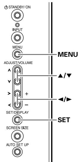
Display operating panel
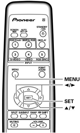
Remote control unit
1 Press the MENU button to display the menu screen.
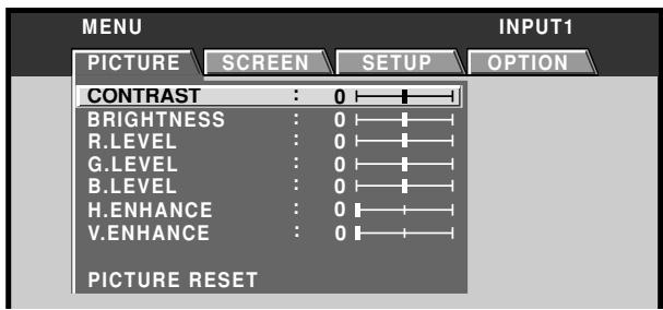
2 Use the / buttons to select [OPTION].
![PIONEER PDA-5004 - Use the / buttons to select [OPTION]. - 1](/content/2025/01/118616/images/209d8e452a7d082faa311902a7b0e708cefacaf2bb41b1167147d9856b9545c5.jpg)
3 Press the / buttons to select [ENERGY SAVE].
![PIONEER PDA-5004 - Press the / buttons to select [ENERGY SAVE]. - 1](/content/2025/01/118616/images/a763818c5cc7670baa4673f439340323e3270e09255cf9b213811bb4b5259bcb.jpg)
4 Press the SET button to select [ENERGY SAVE] setting.
The factory default setting is [STANDARD].
Each time the SET button is pressed, the setting changes as follows:
![PIONEER PDA-5004 - Press the SET button to select [ENERGY SAVE] setting. - 1](/content/2025/01/118616/images/db9d12e24ee227da73c66dbf0f888a126bf221e8f77ed1786fd224241957c1f4.jpg)
- STANDARD ... Brightness is controlled in
accordance with input signal to produce bright, easily viewed in
- MODE1 ....... Brightness is controlled in
accordance with input signal, but power consumption is less than 1 used in [STANDARD] mode.
- MODE2 ....... Brightness is controlled in accordance
with input signal, but power consumption is less than that used in [MODE1].
- MODE3 ....... Brightness is set at fixed level,
regardless of input signal level. Effective at reducing screen aging due to burned lag images, etc.
- AUTO Brightness is set automatically in
response to ambient lighting conditions so as to produce optimum image appearance.
5 When finished with the setting, press the MENU button to return to the normal screen image.
Note
The [ENERGY SAVE] setting affects all input sources.
Changing the color temperature (COLOR TEMP.)

Display operating panel
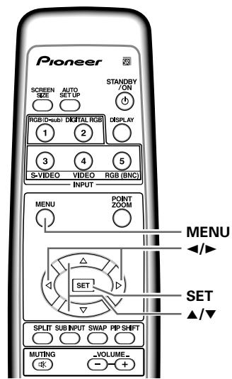
Remote control unit
1 Press the MENU button to display the menu screen.
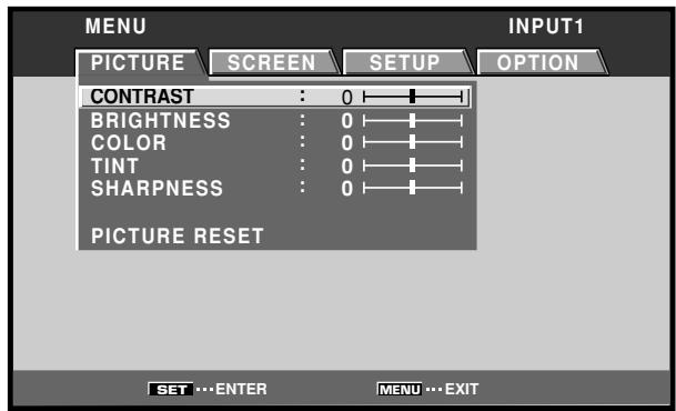
2 Use the / buttons to select [SETUP].
![PIONEER PDA-5004 - Use the / buttons to select [SETUP]. - 1](/content/2025/01/118616/images/9c615c120f20bb1843e35ae4ece1ce15ec400f43fbe06e93b4d6a0eebb706cd7.jpg)
3 Use the / buttons to select [COLOR TEMP.], then press the SET button.
![PIONEER PDA-5004 - Use the / buttons to select [SETUP]. - 2](/content/2025/01/118616/images/cc1bab929132f486826dfc191cb7a8b16100a40ec8d762646418623033d65718.jpg)
4 Use the / buttons to select the desired color temperature setting.
![PIONEER PDA-5004 - Use the / buttons to select [SETUP]. - 3](/content/2025/01/118616/images/db574ca4ba986138877d062f3e15af8dd5e7da2097e405545c07b775d2d6926b.jpg)
The factory default setting is [MIDDLE]. Each time the button is pressed, the color temperature setting changes as shown:
![PIONEER PDA-5004 - Use the / buttons to select [SETUP]. - 4](/content/2025/01/118616/images/fbf4a24ae1d16d688a12353da10d93f2c9cc04be835c8598ca39716312923cc2.jpg)
5 Press the SET button.
The [COLOR TEMP.] function is set and the screen returns to that shown in step 4.
6 When finished with the setting, press the MENU button to return to the normal screen image.
Note
[COLOR TEMP.] settings are supported only for input signal from a video component. Make settings individually for each input (INPUT1 to INPUT5), and for each signal type. (For INPUT2, PDP-505CMX/PDP-50MXE10/PDP-50MXE11 only)
Reducing video noise (DNR)
Make this setting if video noise is objectionable.
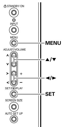
Display operating panel
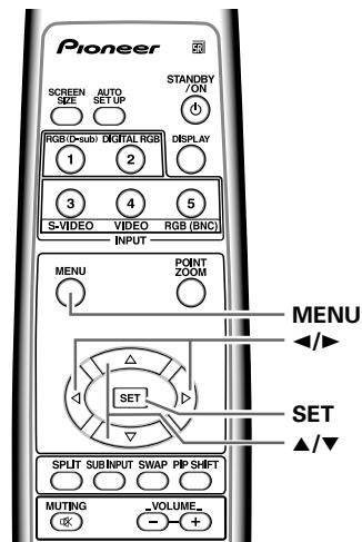
Remote control unit
1 Press the MENU button to display the menu screen.
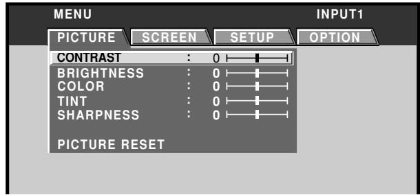
2 Use the / buttons to select [SETUP].
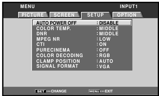
3 Use the / buttons to select [DNR], then press the SET button.
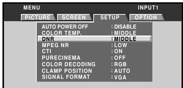
4 Use the / buttons to select the desired [DNR] setting.
![PIONEER PDA-5004 - Use the / buttons to select the desired [DNR] setting. - 1](/content/2025/01/118616/images/035a04602ceb93ea02f002f68f1e25a70a17dceaad03150ef5cde794793c65d0.jpg)
The factory default setting is [MIDDLE]. Each time the button is pressed, the digital noise reduction setting changes as shown:
![PIONEER PDA-5004 - Use the / buttons to select the desired [DNR] setting. - 2](/content/2025/01/118616/images/d17815b2e21f0356d189d7a443f18cda44f58ac7c7fa306108ef0a22b90f00cb.jpg)
- The noise reduction effect increases in order LOW
→ MIDDLE → HIGH
5 Press the SET button.
The [DNR] function is set and the screen returns to that shown in step 4.
6 When finished with the setting, press the MENU button to return to the normal screen image.
Note
[DNR] settings are supported only for input signal from a video component. Make settings individually for each input (INPUT1 to INPUT5), and for each signal type. (For INPUT2, PDP-505CMX/PDP-50MXE10/PDP-50MXE11 only)
Reducing noise in MPEG images (MPEG NR)
Set this function if digital broadcasts, DVD and other MPEG images are distorted with so-called "mosquito noise".
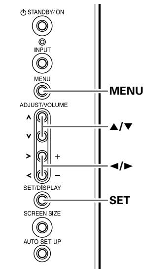
Display operating panel

Remote control unit
1 Press the MENU button to display the menu screen.

2 Use the / buttons to select [SETUP].
![PIONEER PDA-5004 - Use the / buttons to select [SETUP]. - 1](/content/2025/01/118616/images/5d90d75d8d6d264d30b2d98709856c48828a0e6afb9fcfb686b6a765abb1f69b.jpg)
3 Use the / buttons to select [MPEG NR], then press the SET button.
![PIONEER PDA-5004 - Use the / buttons to select [MPEG NR], then press the SET button. - 1](/content/2025/01/118616/images/3cea5b95132fa8c63b34dc84f3b9cea16190330b6642d0f383eae50b78b340cf.jpg)
4 Use the / buttons to select the desired [MPEG NR] setting.
![PIONEER PDA-5004 - Use the / buttons to select the desired [MPEG NR] setting. - 1](/content/2025/01/118616/images/1a7706ed916744a876e19d352637ac2eed9fc7cad7f2e05f5ffa3b6dbd3e1569.jpg)
The factory default setting is [LOW]. Each time the button is pressed, the noise reduction setting changes as shown:
![PIONEER PDA-5004 - Use the / buttons to select the desired [MPEG NR] setting. - 2](/content/2025/01/118616/images/5471d0a4c19478467c07f9c56866396a764f0d454f7f17aa9357d93b58ee15d5.jpg)
- The noise reduction effect increases in order LOW → MIDDLE → HIGH
5 Press the SET button.
The [MPEG NR] function is set and the screen returns to that shown in step 4.
6 When finished with the setting, press the MENU button to return to the normal screen image.
Note
[MPEG NR] settings are supported only for input signal from a video component. Make settings individually for each input (INPUT1 to INPUT5), and for each signal type. (For INPUT2, PDP-505CMX/PDP-50MXE10/PDP-50MXE11 only)
Increasing color border contrast (CTI)
Enhance color contour contrast as desired.
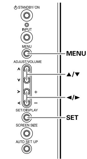
Display operating panel
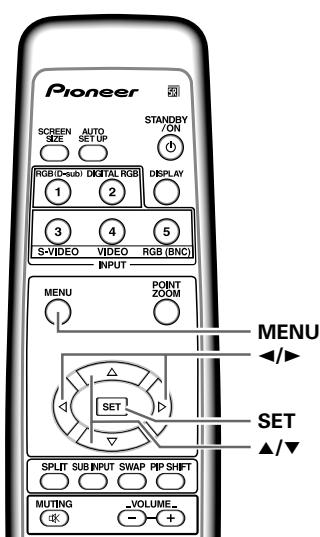
Remote control unit
1 Press the MENU button to display the menu screen.

2 Use the / buttons to select [SETUP].
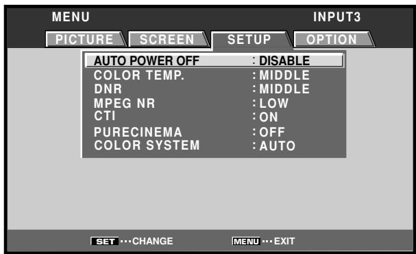
3 Use the / buttons to select [CTI], then press the SET button.
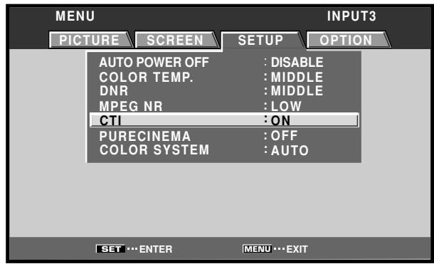
4 Use the / buttons to select the desired [CTI] setting.
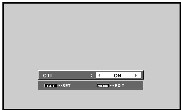
The factory default setting is [ON]. Each time the button is pressed, the setting changes as shown:
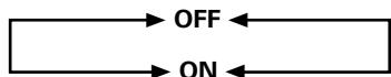
5 Press the SET button.
The [CTI] function is set and the screen returns to that shown in step 4.
6 When finished with the setting, press the MENU button to return to the normal screen image.
Note
[CTI] settings are supported only for input signal from a video component. Make settings individually for each input (INPUT1 to INPUT5), and for each signal type. (For INPUT2, PDP-505CMX/PDP-50MXE10/PDP-50MXE11 only)
Setting the PURECINEMA mode
Allows even higher fidelity DVD playback of film recordings and other images.
Note
Make settings individually for each input (INPUT1 to INPUT5), and for each signal type. (For INPUT2, PDP-505CMX/PDP-50MXE10/PDP-50MXE11 only)
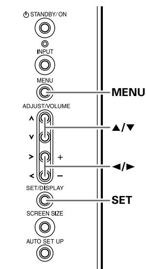
Display operating panel

Remote control unit
1 Press the MENU button to display the menu screen.

2 Use the / buttons to select [SETUP].
![PIONEER PDA-5004 - Use the / buttons to select [SETUP]. - 1](/content/2025/01/118616/images/5482376546a570695004326ff066428c7f95ad7476a5d2679716b65dff05bc69.jpg)
3 Use the / buttons to select [PURECINEMA].
![PIONEER PDA-5004 - Use the / buttons to select [PURECINEMA]. - 1](/content/2025/01/118616/images/d945880890bcf9f61bc25a80bae1eb72062226df488036cd0ebc8707dd692aaf.jpg)
4 Use the / buttons to select the desired [PURECINEMA] mode.
![PIONEER PDA-5004 - Use the / buttons to select the desired [PURECINEMA] mode. - 1](/content/2025/01/118616/images/d63c3735943352527b2b2dcd83fd05a76fd90bdc9d82f7fec5f04b92365378ce.jpg)
The factory default setting is [OFF].
Each time the button is pressed, the screen mode setting changes as shown:
![PIONEER PDA-5004 - Use the / buttons to select the desired [PURECINEMA] mode. - 2](/content/2025/01/118616/images/d162bed78abd45aa68a507cf6b4304eeaf771b3c9a6618533143269d31dbbf75.jpg)
OFF [PURECINEMA] function is disabled.
STANDARD .... When playing DVDs and Hi-Vision film images recorded at 24 frames/sec, the recorded data is automatically detected and adjustments made to allow optimum experience of the original beauty of the film image.
- ADVANCE ...... When playing DVDs of film images recorded at 24 frames/sec, the recorded video information is automatically detected and signals are converted to 72Hz for playback, thus recreating the fluid movement of a movie theater screen, and the sense of film's true visual quality.
Note
During the input of video signals, the modes selectable may differ depending on the type of signal input. For details, consult "Appendix 3: PURECINEMA signal compatibility table" (page 47).
5 Press the SET button.
The [PURECINEMA] function is set and the screen returns to that shown in step 4.
6 When finished with the setting, press the MENU button to return to the normal screen image.
Setting the COLOR SYSTEM
INPUT3 and INPUT4 are compatible with a number of TV system formats used around the world, which are automatically detected by this unit.
Normally [COLOR SYSTEM: AUTO] should be selected for automatic detection. However, some video signals are dubbed over or in certain conditions may not be displayed properly (loss of color, etc.) by this setting. In this case, change the setting according to the input signal.
Note
Setting the TV system format is required for each input (INPUT3 and INPUT4). Setting assignment and exclusive use according to the TV system format of your input signal will enable prompt processing of signals and reduction of time for input selection and possible errors in detecting signals.
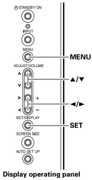
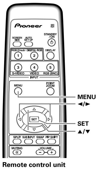
1 Press the MENU button to display the menu screen.

2 Use the / buttons to select [SETUP].
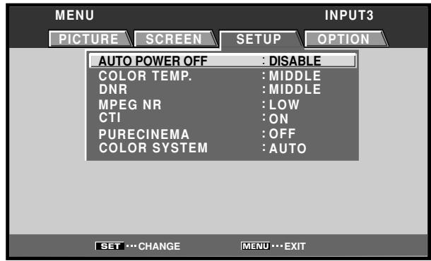
3 Use the / buttons to select [COLOR SYSTEM].
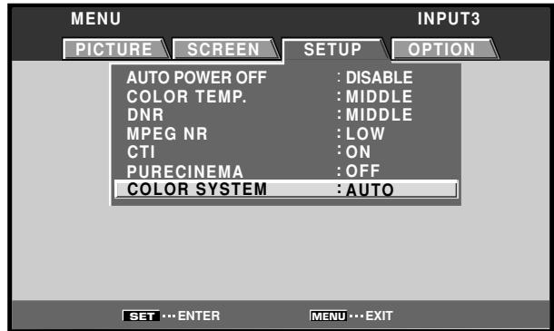
4 Press the SET button repeatedly until the appropriate setting appears.
The factory default setting is [AUTO].
Each time SET button is pressed, the settings change in the following order:


5 When the setup is finished, press the MENU button to exit the menu screen.
Automatic input switching (AUTO FUNCTION)
The plasma display is equipped with an [AUTO FUNCTION] detection function; when a signal is detected at the selected input, the function selector automatically switches to that input.
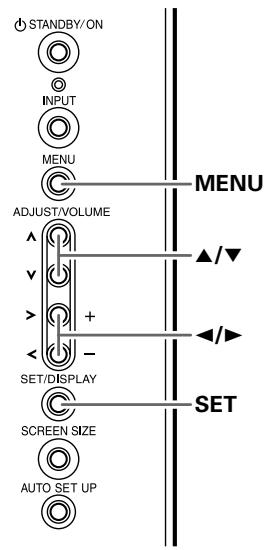
Display operating panel
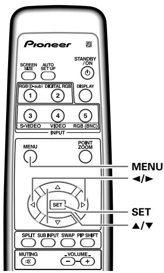
Remote control unit
1 Press the MENU button to display the menu screen.

2 Use the / buttons to select [OPTION].
![PIONEER PDA-5004 - Use the / buttons to select [OPTION]. - 1](/content/2025/01/118616/images/60148571d5663ee78393a676b98fc273a50de7b07557378a5309e388db5e2555.jpg)
3 Use the / buttons to select [AUTO FUNCTION].
![PIONEER PDA-5004 - Use the / buttons to select [AUTO FUNCTION]. - 1](/content/2025/01/118616/images/31aa656492d4344385bccf7581982cd2ae2dbcf8d6c3ac7a169cafbf65c1021f.jpg)
4 Press the SET button to select the desired [AUTO FUNCTION] setting.
The factory default setting is [OFF].
Each time the SET button is pressed the selector function switches alternately as shown:
![PIONEER PDA-5004 - Press the SET button to select the desired [AUTO FUNCTION] setting. - 1](/content/2025/01/118616/images/939bf2b4264dc92dda8febb9ef922a358242626a3091bf79fcad28619d6c0e01.jpg)
- OFF ....... [AUTO FUNCTION] is disabled.
-
INPUT1 or INPUT4...
-
If a signal is detected to the selected input jack, the input function will automatically switch to the selected input.
-
Once the function has switched to the selected input by operation of the [AUTO FUNCTION] facility, if the input signal is no longer detected at the selected input jack, the function will automatically switch back to the original input source used before the [AUTO FUNCTION] facility was enabled.
- If the input changes when the unit is in [AUTO FUNCTION] mode, pressing the INPUT button to select a different input will cause the [AUTO FUNCTION] mode to be temporarily disabled, but it can be enabled again by turning the power OFF/ON.
5 When finished with the setting, press the MENU button to return to the normal screen image.
Notes
- The [AUTO FUNCTION] for [INPUT1] is supported only when a separate SYNC or Composite SYNC analog RGB signal is input ([AUTO FUNCTION] is disabled when a G ON SYNC or component video signal is input).
- The [AUTO FUNCTION] setting affects all input sources.
About audio output (AUDIO OUT) (PDP-504CMX/PDP-50MXE1/ PDP-50MXE1-S and PDP-434CMX/ PDP-43MXE1/PDP-43MXE1-S only)
The signal level produced at the AUDIO (OUTPUT) jack can be set to [FIXED] or [VARIABLE] (linked to the VOLUME) as desired.
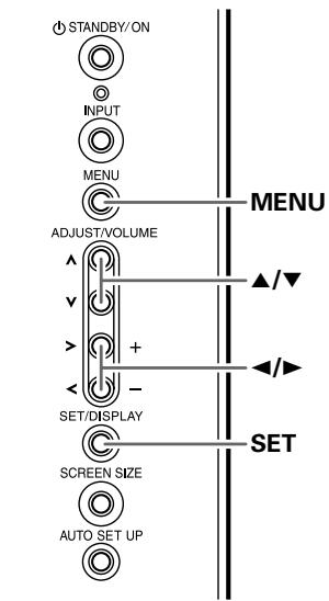
Display operating panel
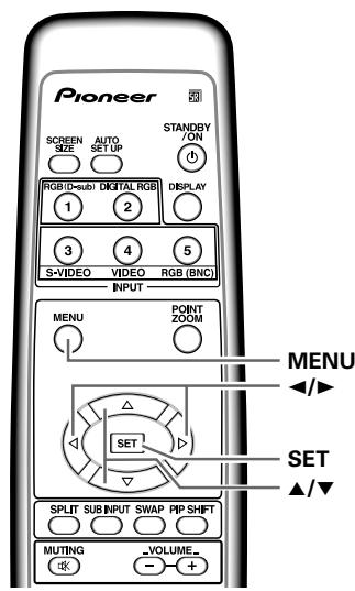
Remote control unit
1 Press the MENU button to display the menu screen.

2 Use the / buttons to select [OPTION].
![PIONEER PDA-5004 - Use the / buttons to select [OPTION]. - 1](/content/2025/01/118616/images/c4ecbef28394d04702b699f761f6e1a72f01a5a1406156d8289eb39aba8c2937.jpg)
3 Use the / buttons to select [AUDIO OUT].
![PIONEER PDA-5004 - Use the / buttons to select [AUDIO OUT]. - 1](/content/2025/01/118616/images/fedc1df7b5937a9688c89c0b8b0207e89f977fc1f759dd1fbee45ccbe1c04ad1.jpg)
4 Press the SET button to select the desired audio level setting.
The factory default setting is [FIXED]. Each time the SET button is pressed, the function alternates as shown:
- FIXED Audio output volume remains fixed, even if the VOLUME controls are operated.
- VARIABLE .... Audio output volume changes in response to operation of VOLUME controls.
5 When finished with the setting, press the MENU button to return to the normal screen image.
Notes
- The [AUDIO OUT] setting affects all input sources.
- The volume of the sound output obtained from the AUDIO terminal of PDP-505CMX/PDP-50MXE10/PDP-50MXE11 is [VARIABLE].
Specifications
General
External dimensions
PDA-5003 301.5 (W) x 27.6 (H) x 148.9 (D) mm
11-7/8 (W) x 1-1/8 (H) x 5-7/8 (D) in.
PDA-5004 301.5 (W) x 27.6 (H) x 148.3 (D) mm
11-7/8 (W) x 1-1/8 (H) x 5-27/32 (D) in.
Weight 0.4 kg (14 oz)
Operating temperature range ....... 0 to 40ircC (32 to 104ircF )
PDA-5003
Input/output
Video
INPUT3
Input
S jack (Mini DIN 4 pin)
Y/C separate video signal
Y. .1 Vp-p/75 Ω/negative sync.
C. . . . 0.286 Vp-p/75 Ω (NTSC)
0.3 Vp-p/75 Ω (PAL)
INPUT4
Input
BNC jack
Composite video signal
1 Vp-p/75 Ω/negative sync.
Output
BNC jack
75 Ω /with buffer
INPUT5
Input
BNC jack (x5)
- RGB signal (G ON SYNC compatible)
RGB ... 0.7 Vp-p/75 Ω/no sync.
HD/VS, VD ... TTL level
/positive and negative polarity/
75 Ω or 2.2 kΩ
(impedance switch)
G ON SYNC ...
1 Vp-p/75 Ω/negative sync.
- Component video signal
Y...1 Vp-p / 75 Ω negative sync.
AUDIO INPUT (for INPUT3/4)
Pin jack (x2)
L/R ... 500mVrms/more than 10 kΩ
AUDIO INPUT (for INPUT5)
Pin Jack (x2)
L/R ... 500mVrms/more than 10 kΩ
PDA-5004
Input/output
Video
INPUT3
Input
S jack (Mini DIN 4 pin)
Y/C separate video signal
Y . . . 1 Vp-p/75 Ω/negative sync.
C. . . . 0.286 Vp-p/75 Ω (NTSC)
0.3 Vp-p/75 Ω (PAL)
INPUT4
Input
RCA jack
Composite video signal
1 Vp-p/75 Ω /negative sync.
Output
RCA jack
75Ω/withbuffer
INPUT5
Input
RCA jack
- RGB signal (G ON SYNC compatible)
RGB ... 0.7 Vp-p/75 Ω/no sync.
G ON SYNC ...
1 Vp-p/75 Ω/negative sync.
- Component video signal
Y...1 Vp-p / 75 Ω negative sync.
AUDIO INPUT (for INPUT3)
Pin Jack (x2)
L/R ... 500mVrms/more than 10kΩ
AUDIO INPUT (for INPUT4)
Pin Jack (x2)
L/R ... 500mVrms/more than 10kΩ
AUDIO INPUT (for INPUT5)
Pin jack (x2)
L/R ... 500mVrms/more than 10kΩ
Accessories
Label for remote control unit 1
Connector indicator label 1
Screws 2
Operating Instructions 1
Warranty 1
- Due to improvements, specifications and design are subject to change without notice.
Appendix 1
Video signal compatibilty table (INPUT1, INPUT5)
Not available.
| Refresh rate | Signal format | Screen size | Remarks | |||||
| Vertical fv (Hz) | Horizontal fh (kHz) | 4:3 | FULL | ZOOM | CINEMA | WIDE | ||
| 50 | 15.625 | Component | ○ | ○ | ○ | ○ | ○ | 625i (576i)/SDTV |
| RGB | ○ | ○ | ○ | ○ | ○ | |||
| 28.13 | Component | ○ | ○ | 1125i (1080i)/HDTV | ||||
| RGB | ○ | ○ | ||||||
| 31.25 | Component | ○ | ○ | ○ | ○ | ○ | 625p (576p)/SDTV | |
| RGB | ○ | ○ | ○ | ○ | ○ | |||
| 37.50 | Component | ○ | ○ | 750p (720p)/HDTV | ||||
| RGB | ○ | ○ | ||||||
| 56.20 | Component | ○*2 | 1125p (1080p)/HDTV | |||||
| RGB | ○*2 | |||||||
| 62.50 | Component | ○*2 | 1250p/HDTV | |||||
| RGB | ○*2 | |||||||
| 60 | 15.734 | Component | ○ | ○ | ○ | ○ | ○ | 525i (480i)/SDTV |
| RGB | ○ | ○ | ○ | ○ | ○ | |||
| 31.5 | Component | ○ | ○ | ○ | ○ | ○ | 525p (480p)/SDTV | |
| RGB | ○ | ○ | ○ | ○ | ○ | |||
| 33.75 | Component | ○*1 | ○ | 1125i (1080i)/HDTV | ||||
| RGB | ○*1 | ○ | 1125i (1035i)/HDTV | |||||
| 45.0 | Component | ○ | ○ | 750p (720p)/HDTV | ||||
| RGB | ○ | ○ | ||||||
| 67.5 | Component | ○*2 | 1125p (1080p)/HDTV | |||||
| RGB | ○*2 | |||||||
1: Can be selected from either [FULL1080i] or [FULL1035i].
2: Some visual distortion may occur depending on the combination of connected components.
Video signal compatibilty table (INPUT2)
(PDP-505CMX/PDP-50MXE10/PDP-50MXE11 only)
Not available.
| Refresh rate | Signal format | Screen size | Remarks | |||||
| Vertical fv (Hz) | Horizontal fh (kHz) | 4:3 | FULL | ZOOM | CINEMA | WIDE | ||
| 50 | 15.625 | Component | ○ | ○ | ○ | ○ | ○ | 625i (576i)/SDTV |
| RGB | ○ | ○ | ○ | ○ | ○ | |||
| 28.13 | Component | ○ | ○ | 1125i (1080i)/HDTV | ||||
| RGB | ○ | ○ | ||||||
| 31.25 | Component | ○ | ○ | ○ | ○ | ○ | 625p (576p)/SDTV | |
| RGB | ○ | ○ | ○ | ○ | ○ | |||
| 37.50 | Component | ○ | ○ | 750p (720p)/HDTV | ||||
| RGB | ○ | ○ | ||||||
| 60 | 15.734 | Component | ○ | ○ | ○ | ○ | ○ | 525i (480i)/SDTV |
| RGB | ○ | ○ | ○ | ○ | ○ | |||
| 31.5 | Component | ○ | ○ | ○ | ○ | ○ | 525p (480p)/SDTV | |
| RGB | ○ | ○ | ○ | ○ | ○ | |||
| 33.75 | Component | ○*1 | ○ | 1125i (1080i)/HDTV | ||||
| RGB | ○*1 | ○ | 1125i (1035i)/HDTV | |||||
| 45.0 | Component | ○ | ○ | 750p (720p)/HDTV | ||||
| RGB | ○ | ○ | ||||||
*1: Can be selected from either [FULL1080i] or [FULL1035i].
Appendix 2
Computer signal compatibility table (when connected to PDP-505CMX/PDP-504CMX/ PDP-50MXE10/PDP-50MXE11/PDP-50MXE1/PDP-50MXE1-S) (INPUT1 and INPUT5)
Not available.
| Resolution(Dot x Line) | Refresh rate | Screen size (Dot x line) | Remarks | ||||
| Vertical | Horizontal | DOT BY DOT | 4:3 | FULL | PARTIAL | ||
| 640x400 | 56.4Hz | 24.8kHz | 1280x768 | NEC PC-9800 | |||
| 720x400 | 70.1Hz | 31.5kHz | 1280x768 | NEC PC-9800 | |||
| 85.1Hz | 37.9kHz | ↑ | |||||
| 640x480 | 60Hz | 31.5kHz | 640x480 | 1024x768 | 1280x768 | ||
| 66.7Hz | 35.0kHz | ↑ | ↑ | ↑ | Apple Macintosh 13" | ||
| 72.8Hz | 37.9kHz | ↑ | ↑ | ↑ | |||
| 75Hz | 37.5kHz | ↑ | ↑ | ↑ | |||
| 85Hz | 43.3kHz | ↑ | ↑ | ↑ | |||
| 848x480 | 60Hz | 31.0kHz | 848x480 | 1280x768 | |||
| 800x600 | 56Hz | 35.2kHz | 800x600 | 1024x768 | 1280x768 | ||
| 60Hz | 37.9kHz | ↑ | ↑ | ↑ | (1072x600) | ||
| 72Hz | 48.1kHz | ↑ | ↑ | ↑ | |||
| 75Hz | 46.9kHz | ↑ | ↑ | ↑ | |||
| 85Hz | 53.7kHz | ↑ | ↑ | ↑ | |||
| 832x624 | 74.6Hz | 49.7kHz | 832x624 | 1024x768 | 1280x768 | Apple Macintosh 16" | |
| 1024x768 | 60Hz | 48.4kHz | 1024x768 | 1280x768 | (1376 x 768) | ||
| 70Hz | 56.5kHz | ↑ | ↑ | ||||
| 75Hz(74.9Hz) | 60.0kHz(60.2kHz) | ↑ | ↑ | () indicates Apple Macintosh 19" | |||
| 85Hz | 68.7kHz | ↑ | ↑ | ||||
| 1280x720 | 60Hz | 44.7kHz | 1280x720 | 1280x768 | |||
| 1280x768 | 56Hz | 45.1kHz | 1280x768 | ||||
| 60Hz | 47.8kHz | ↑ | |||||
| 70Hz | 56.1kHz | ↑ | |||||
| 1152x864 | 60Hz | 53.7kHz | 1024x768 | 1280x768 | |||
| 72Hz | 64.9kHz | ↑ | ↑ | ||||
| 75Hz | 67.5kHz | ↑ | ↑ | ||||
| 1152x870 | 75.1Hz | 68.5kHz | 1024x768 | 1280x768 | Apple Macintosh 21" | ||
| 1152x900 | 66Hz | 61.8kHz | 1024x768 | 1280x768 | Sun Microsystems LO | ||
| 76Hz | 71.7kHz | ↑ | ↑ | Sun Microsystems HI | |||
| 1280x960 | 60Hz | 60.0kHz | 1024x768 | 1280x768 | |||
| 1280x1024 | 60Hz | 64.0kHz | 1024x768 | 1280x768 | 1280x768 | ||
| 75Hz | 80.0kHz | ↑ | ↑ | ↑ | (1600x1024) | ||
| 85Hz | 91.2kHz | ↑ | ↑ | ↑ | |||
| 1400x1050 | 60Hz | 65.3kHz | 1024x768 | 1280x768 | |||
| 75Hz | 82.3kHz | ↑ | ↑ | ||||
| 85Hz | 93.9kHz | ↑ | ↑ | ||||
| 1600x1200 | 60Hz | 75.0kHz | 1024x768 | 1280x768 | |||
| 65Hz | 81.3kHz | ↑ | ↑ | ||||
| 70Hz | 87.5kHz | ↑ | ↑ | ||||
| 75Hz | 93.8kHz | ↑ | ↑ | ||||
| 85Hz | 106.3kHz | ↑ | ↑ | ||||
Computer signal compatibility table (when connected to PDP-434CMX/PDP-43MXE1/PDP-43MXE1-S) (INPUT1 and INPUT5)
| Resolution(Dot x Line) | Refresh rate | Screen size (Dot x line) | Remarks | ||||
| Vertical | Horizontal | DOT BY DOT | 4:3 | FULL | ZOOM | ||
| 640x400 | 56.4Hz | 24.8kHz | ○1024x768 | NEC PC-9800 | |||
| 720x400 | 70.1Hz | 31.5kHz | ○1024x768 | NEC PC-9800 | |||
| 85.1Hz | 37.9kHz | ↑ | |||||
| 640x480 | 60Hz | 31.5kHz | ◎640x480 | ○768x768 | ○1024x768 | ||
| 66.7Hz | 35.0kHz | ↑ | ↑ | ↑ | Apple Macintosh 13" | ||
| 72.8Hz | 37.9kHz | ↑ | ↑ | ↑ | |||
| 75Hz | 37.5kHz | ↑ | ↑ | ↑ | |||
| 85Hz | 43.3kHz | ↑ | ↑ | ↑ | |||
| 848x480 | 60Hz | 31.0kHz | ◎848x480 | ○1024x768 | |||
| 800x600 | 56Hz | 35.2kHz | ◎800x600 | △768x768 | ○1024x768 | ||
| 60Hz | 37.9kHz | ↑ | ↑ | ↑ | (1072x600) | ||
| 72Hz | 48.1kHz | ↑ | ↑ | ↑ | |||
| 75Hz | 46.9kHz | ↑ | ↑ | ↑ | |||
| 85Hz | 53.7kHz | ↑ | ↑ | ↑ | |||
| 832x624 | 74.6Hz | 49.7kHz | ◎832x624 | △768x768 | ○1024x768 | Apple Macintosh 16" | |
| 1024x768 | 60Hz | 48.4kHz | ◎1024x768 | △768x768 | (1376 x 768) | ||
| 70Hz | 56.5kHz | ↑ | ↑ | ||||
| 75Hz(74.9Hz) | 60.0kHz(60.2kHz) | ↑ | ↑ | () indicates Apple Macintosh 19" | |||
| 85Hz | 68.7kHz | ↑ | ↑ | ||||
| 1280x720 | 60Hz | 44.7kHz | △1024x768 | ||||
| 1280x768 | 56Hz | 45.1kHz | △1024x768 | ||||
| 60Hz | 47.8kHz | ↑ | |||||
| 70Hz | 56.1kHz | ↑ | |||||
| 1152x864 | 60Hz | 53.7kHz | △768x768 | △1024x768 | |||
| 72Hz | 64.9kHz | ↑ | ↑ | ||||
| 75Hz | 67.5kHz | ↑ | ↑ | ||||
| 1152x870 | 75.1Hz | 68.7kHz | △768x768 | △1024x768 | Apple Macintosh 21" | ||
| 1152x900 | 66Hz | 61.8kHz | △768x768 | △1024x768 | Sun Microsystems LO | ||
| 76Hz | 71.7kHz | ↑ | ↑ | Sun Microsystems HI | |||
| 1280x960 | 60Hz | 60.0kHz | △768x768 | △1024x768 | |||
| 1280x1024 | 60Hz | 64.0kHz | △768x768 | △1024x768 | △1024x768 | ||
| 75Hz | 80.0kHz | ↑ | ↑ | ↑ | (1600x1024) | ||
| 85Hz | 91.2kHz | ↑ | ↑ | ↑ | |||
| 1400x1050 | 60Hz | 65.3kHz | △768x768 | △1024x768 | |||
| 75Hz | 82.3kHz | ↑ | ↑ | ||||
| 85Hz | 93.9kHz | ↑ | ↑ | ||||
| 1600x1200 | 60Hz | 75.0kHz | △768x768 | △1024x768 | |||
| 65Hz | 81.3kHz | ↑ | ↑ | ||||
| 70Hz | 87.5kHz | ↑ | ↑ | ||||
| 75Hz | 93.8kHz | ↑ | ↑ | ||||
| 85Hz | 106.3kHz | ↑ | ↑ | ||||
[Meaning of symbols] : Optimal picture. Adjustment of picture position, refresh rate, phase etc., may be necessary.
: Picture will be enlarged but some fine detail will be hard to see.
: Simple reproduction. Fine detail will not be reproduced.
Appendix 3
PURECINEMA signal compatibility table (INPUT1, INPUT5)
Not available.
PURECINEMA signal compatibility table (INPUT2)
(PDP-505CMX/PDP-50MXE10/PDP-50MXE11 only)
| Refresh rate | Signal format | PURECINEMA | Remarks | |||
| Vertical fv (Hz) | Horizontal fh (kHz) | OFF | STANDARD | ADVANCE | ||
| 50 | 15.625 | Component RGB | ○○○○○○○○○○○○○○○○○○○○○○○○○○○○○○○○○○○○○○○○○○○○○○○○○○○○○○○○○○○○○○○○○○○○○○○○○○○○○○○○○○○○○○○○○○○○○○○○○○○○ | |||
| 28.13 | Component RGB | ○○○○○○○○○○○○○○○○○○○○○○○○○○○○○○○○○○○○○○○○○○○○○○○○○○○○○○○○○○○○○○○○○○○○○○○○○○○○○○○○○○○○○○○○○○○○○○○ | ||||
| 31.25 | Component RGB | 625p (575p)/SDTV | ||||
| 37.50 | Component RGB | 750p (720p)/HDTV | ||||
| 56.25 | Component RGB | 1125p (1080p)/HDTV | ||||
| 62.50 | Component RGB | 1250p/HDTV | ||||
| 60 | 15.734 | Component RGB | ○○○○○○○○○○○○○○○○○○○○○○○○○○○○○○○○○○○○○○○○○○○○○○○○○○○○○○○○○○○○○○○○○○○○○○○○○○○○○○○○○○○○○○○○○○○○○○○ | ○○○○○○○○○○○○○○○○○○○○○○○○○○○○○○○○○○○○○○○○○○○○○○○○○○○○○○○○○○○○○○○○○○○○○○○○○○○○○○○○○○○○○○○○○○○○○○○○○○ | ||
: Not available.
| Refresh rate | Signal format | PURECINEMA | Remarks | |||
| Vertical fv (Hz) | Horizontal fh (kHz) | OFF | STANDARD | ADVANCE | ||
| 50 | 15.625 | Component RGB | ○○○○○○○○○○○○○○○○○○○○○○○○○○○○○○○○○○○○○○○○○○○○○○○○○○○○○○○○○○○○○○○○○○○○○○○○○○○○○○○○○○○○○○○○○○○○○○○○○○○○ | |||
| 28.13 | Component RGB | ○○○○○○○○○○○○○○○○○○○○○○○○○○○○○○○○○○○○○○○○○○○○○○○○○○○○○○○○○○○○○○○○○○○○○○○○○○○○○○○○○○○○○○○○○○○○○○○ | ||||
| 31.25 | Component RGB | 625p (575p)/SDTV | ||||
| 37.50 | Component RGB | 750p (720p)/HDTV | ||||
| 60 | 15.734 | Component RGB | ○○○○○○○○○○○○○○○○○○○○○○○○○○○○○○○○○○○○○○○○○○○○○○○○○○○○○○○○○○○○○○○○○○○○○○○○○○○○○○○○○○○○○○○○○○○○○○○×××××××××××××××××××××××××××××××××××××××××××××××××××××××××××××××××××××××××××××××××××××××××××××××××××× | |||
| 31.5 | Component RGB | ○○○○○○○○○○○○○○○○○○○○○○○○○○○○○○○○○○○○○○○○○○○○○○○○○○○○○○○○○○○○○○○○○○○○○○○○○○○○○○○○○○○○○○○○○○○○○○ | ||||
| 33.75 | Component RGB | ○○○○○○○○○○○○○○○○○○○○○○○○○○○○○○○○○○○○○○○○○○○○○○○○○○○○○○○○○○○○○○○○○○○○○○○○○○○○○○○○○○○○○○○○○○○○○○×××××times×××××××××××××××××××××××××××××××××××××××××××××××××××××××××××××××××××××××××××××××××××××××××××××××××××times×××××××××××××××××××××××××××××××××××××××××××××××××××××××××××××××××××××××××××××××××××××××××××××times×××××times××××××××××××××××××××××××××××××××××××××××××××××××××××××××××××××××××××××××××××××××××××××××××××× ×××××××××××××××××××××××××××××××××××××××××××××××××××××××××××××××××××××××××××××××××××××××××××××××××××× ×××××× ××××××××××××××××××××××××××××××××××××××××××××××××××××××××××××××××××××××××××××××××××××××××××××××times××××× ×××××××××××××××××××××××××××××××××××××××××××××××××××××××××××××××××××××××××××××××××××××××××××××× ××××××times××××××××××××××××××××××××××××××××××××××××××××××××××××××××××××××××××××××××××××××××××××××××××××× | ||||
Not available.
PURECINEMA signal compatibility table (INPUT3, INPUT4)
| Refresh rate | Signal format | PURECINEMA | Remarks | |||
| Vertical fv (Hz) | Horizontal fh (kHz) | OFF | STANDARD | ADVANCE | ||
| 50 | 15.625 | Composite S Video | ○○○ | ○○○ | ○○○ | 625i (575i)/SDTV |
| 60 | 15.734 | Composite S Video | ○○○ | ○○○ | ○○○ | 525i (480i)/SDTV |
Appendix 4
INPUT1 (Mini D-sub 15 pin female connector) pin allocation.
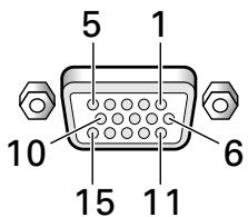
| Pin No. | Input | Output |
| 1 | R | ← |
| 2 | G | ← |
| 3 | B | ← |
| 4 | NC (No connection) | ← |
| 5 | GND | ← |
| 6 | GND | ← |
| 7 | GND | ← |
| 8 | GND | ← |
| 9 | DDC + 5V | NC (No connection) |
| 10 | GND | ← |
| 11 | NC (No connection) | ← |
| 12 | DDC SDA | NC (No connection) |
| 13 | HD or H/V SYNC | ← |
| 14 | VD | ← |
| 15 | DDC SCL | NC (No connection) |
Explanation of Terms
Aspect ratio
The TV screen's width to height ratio is referred to as its aspect ratio. The aspect ratio on standard TVs is 4:3 and on wide TVs or High Definition TVs it is 16:9.
S jack (SVIDEO jack)
This jack separates and transmits the video signal as two signals; the luminance (Y) signal and the color(C) signal. Because of this, picture reproduction is superior to that obtained at the composite input/output jacks.
S-video signal
The video signal is composed of two signals; the chroma signal (color signal) which reproduces color and the luminance signal which reproduces light and darkness. With standard video components, these two signals are combined into one and are handled as a video signal referred to as the "composite signal". The S-video signal, however, is a signal that handles these two signals separately. Because they are not combined as in the composite video signal, the high quality of both signals can be retained.
Component video signal
General term for video signal format composed of the Y.CBCRdot Y.PBPR and Y.B-Y.R-Y luminance signal ^+ color signal. The component video signal is sometimes simply called the "color difference signal".
G ON SYNC
This indicates a video signal in the form of a synchronization signal added to the G (GREEN) signal of the R.G.B signal.
VGA
General term for "Video Graphics Array". Generally this indicates a 640 dot x 480 line resolution.
WVGA
General term for "Wide Video Graphics Array". Generally this indicates a 848 dot x 480 line resolution.
XGA
General term for "eXtended Graphics Array". Generally this indicates a 1024 dot x 768 line resolution.
WXGA
General term for "Wide eXtended Graphics Array". Generally this indicates a 1280 dot x 768 line resolution.
SXGA
General term for "Super eXtended Graphics Array". Generally this indicates a 1280 dot x 1024 line resolution.
SXGA+
General term for "Super eXtended Graphics Array plus". Generally this indicates a 1400 dot x 1050 line resolution.
DVI
General term for "Digital Visual Interface". An interface standard proposed by the Digital Display Working Group (DDWG) for digital displays.
HDCP
General term for "High-bandwidth Digital Content Protection". HDCP is an encryption scheme for digital video signals created by Intel in order to protect contents. Signals output by HDCP-compliant DVI output connectors installed on consumer AV components (DVD players, etc.) are encrypted using HDCP in order to protect copyrighted contents.
This component uses NEC's Font Avenue as its screen display font.
Font Avenue is a registered trademark of NEC.
Power Management is a registered trademark of Sun Microsystems Inc.
TMDS is a registered trademark of Silicon Image Inc.
Apple and Macintosh are registered trademarks of Apple Computer, Inc.
Microsoft is a registered trademark of Microsoft Corporation. VGA and XGA are registered trademarks of International Business Machines Co., Inc.
VESA and DDC are registered trademarks of Video Electronic Standards Association.
Published by Pioneer Corporation. Copyright © 2005 Pioneer Corporation. All rights reserved.
IMPORTANT

This Class B digital apparatus complies with Canadian ICES-003.
Installation et raccordements 6
⑤ ANALOG RGB OUT (INPUT1)
⑭VIDEO IN (INPUT4) (prise BNC)
⑮VIDEO OUT (INPUT4) (prise BNC)
⑰ ANALOG RGB (INPUT5) (prises BNC)
Prise S (mini DIN 4 broches)
Signal video Y/C séparé
Y (luminance) ...... 1 Vcc/75 Ohms, synchronégative
C (chrominance) ... 0,286 Vcc/75 Ohms (NTSC)
0,3 Vcc/75 Ohms (PAL)
INPUT4
(Entrée) Prise BNC
- Signal video composite
1 Vcc/75 Ohms, synchro négative
Sortie Prise BNC
(Entree) Prise S (mini DIN 4 broches)
- Signal video Y/C séparé
Y (luminance) ...... 1 Vcc/75 Ohms, synchroné negative
C (chrominance) ... 0,286 Vcc/75 Ohms (NTSC)
0,3 Vcc/75 Ohms (PAL)
INPUT4
(Entrée) Prise RCA
- Signal video composite
1 Vcc/75 Ohms, synchro négative
Sortie Prise RCA
Electronics Standards Association.
Publication de Pioneer Corporation.
© 2005 Pioneer Corporation
⑰ ANALOG RGB (INPUT5)
AFTER-SALES SERVICE FOR PIONEER PRODUCTS
Please contact the dealer or distributor from where you purchased the product for its after-sales service (including warranty conditions) or any other information. In case the necessary information is not available, please contact the Pioneer's subsidiaries (regional service headquarters) listed below:
PLEASE DO NOT SHIP YOUR PRODUCT TO THE COMPANIES at the addresses listed below for repair without advance contact, for these companies are not repair locations.
AMERICA
PIONEER ELECTRONICS (USA) INC.
Customer Support Division
PO BOX 1760 Long Beach, Ca. 90801-1760, U.S.A
Tel: 1-800-421-1625
EUROPE
PIONEER EUROPE NV
European Service Division
Haven 1087, Keetberglaan 1, 9120 Melsele, Belgium
Tel: 32-(0)3-570-0511
ASEAN
PIONEER ELECTRONICS ASIACENTRE, PTE.LTD.
Technical Support Department, Service Division
253, Alexandra Road, #04-01, Singapore 159936
Tel: 65-6472-1111
OCEANIA
PIONEER ELECTRONICS AUSTRALIA PTY.LTD.
Pioneer Service&Spares
2211 Princess HWY, Mulgrave VIC3170, Australia
Tel: 61-(0)39586 6380
Tel: 1-800-988-268
MIDDLE EAST
PIONEER GULF FZE
Service Division
Lob 11-017, P.O.Box 61226 Jebel Ali, Dubai, U.A.E.
Tel: 971-4-8815756
JAPAN and Others
PIONEER SERVICE NETWORK Co.
BS Service Division
4-15-5, Ohmori-nishi Otaku Tokyo, 143-8564
Tel:81-(0)3-3763-3129
Printed on recycled paper.
Published by Pioneer Corporation.
Copyright © 2005 Pioneer Corporation.
All rights reserved.
八才二株式会社
PIONEER ELECTRONICS OF CANADA, INC. 300 Allstate Parkway, Markham, Ontario L3R OP2, Canada TEL: 1-905-479-4411
PIONEER EUROPE NV MULTIMEDIA DIVISION Pioneer House Hollybush Hill, Stoke Poges, Slough SL2 4QP, U.K., TEL: 44-1753-789-789
PIONEER ELECTRONICS AUSTRALIA PTY.LTD. 178-184 Boundary Road, Braeside, Victoria 3195, Australia, TEL: 61-39-586-6300
PIONEER ELECTRONICS ASIACENTRE PTE. LTD. 253 Alexandra Road #04-01, Singapore 159936, TEL: 65-6472-1111
PIONEER HIGH FIDELITY TAIWAN CO., LTD. 13FL., No44 Chung Shan North Road, Sec.2. Taipei, Taiwan, TEL: 886-2-2521-3588
PIONEER (HK) LIMITED Suite 901-906, 9th Floor World Commerce Centre, Harbour City 11 Canton Road, Tsim Sha Tsui Kowloon, Hong Kong
TEL: 852-2848-6488
PIONEER GULF FZE Lob 11-017, Jebel Ali Free Zone P.O. BOX 61226, Jebel Ali, Dubai TEL: 971-4-8815756
- 「据付工事」にて
- COMBINATION IN/OUT
- 「映像の調整」の調整項目
- CAUTION
- RISK OF ELECTRIC SHOCK DO NOT OPEN
- CAUTION:
- [For U.S. model]
- FEDERAL COMMUNICATIONS COMMISSION DECLARATION OF CONFORMITY
- WARNING
- Notes on Installation Work:
- Note for Dealers:
- Contents
- Safety Precautions
- Before Proceeding 2
- Part Names and Functions 4
- Installation and Connections 6
- System Settings 18
- Operation 22
- PICTURE/SCREEN Adjustment 28
- Other Operations 32
- Additional Information 43
- Checking supplied accessories
- How to use this manual
- Regarding menu displays
- About operations in this manual
- Note
- PICTURE/SCREEN Adjustment
- [PICTURE] mode adjustment items
- Connection panel
- Plasma Display Section
- ① SPEAKER (R) terminal
- ② COMBINATION IN/OUT
- ③ RS-232C
- ④ ANALOG RGB IN (INPUT1) (mini D-sub 15 pin)
- ⑤ ANALOG RGB OUT (INPUT1) (mini D-sub 15 pin)
- ⑦ DIGITAL RGB (INPUT2) (DVI-D jack)
- Video Card Section
- Installing the video card
- TO USERS:
- TO SALES AGENTS:
- Installation Notes:
- Installation
- Notes
- Input connectors on the plasma display with video card
- When using PDA-5004
- Connection to INPUT1 and INPUT5
- Connection to INPUT1 or INPUT5
- Connection to AV components
- Connection to AV component equipped with component video jacks
- When connecting to ANALOG RGB IN (INPUT1)
- When connecting to ANALOG RGB (INPUT5)
- When connecting to COMPONENTVIDEO(INPUT5) —
- Connection of G ON SYNC analog RGB source
- [Connections for PDA-5003]
- When connecting to COMPONENT VIDEO (INPUT5) — [Connections for PDA-5004]
- Connection of composite SYNC analog RGB source
- Connection to a personal computer
- Connection of separate SYNC analog RGB source
- When connecting to ANALOG RGB OUT (INPUT1) —
- Connection to INPUT2
- NOTICE
- Connection to INPUT3
- Connection to INPUT4
- About DTV set top box connection
- Audio connections
- Connect an audio component to the audio input jack of the plasma display with installed video card.
- Audio connection for component connected to INPUT1
- Audio connections for component connected to INPUT2
- Audio connection for component connected to INPUT5
- [When using PDA-5003]
- Audio connection for component connected to INPUT3 or INPUT4
- [When using PDA-5004]
- Audio connection for component connected to INPUT3
- Audio connection for component connected to INPUT4
- How to route cables
- Organize cables together using the provided speed clamps.
- To attach the speed clamps to the display
- Bunch separated cables together and secure them with the provided bead bands.
- To remove speed clamps
- Setting the onscreen display language
- Settings after connections
- [DVI SELECT] setup
- (PDP-505CMX/PDP-50MXE10/PDP-50MXE11 only)
- Press the MENU button to display the menu screen.
- Use the / buttons to select [OPTION].
- Use the / buttons to select [DVI SELECT].
- Press the SET button and choose the component to be connected.
- When the setup is completed, press the MENU button to exit the menu screen.
- [ SIGNAL FORMAT ] /
- [COLOR DECODING] setup
- Press the SET button.
- When the setup is completed, press MENU to exit the menu screen.
- [CLAMP POSITION] setup
- Use the / buttons to select [SETUP].
- Use the / buttons to select [CLAMP POSITION].
- Press the SET button to select [LOCKED].
- Selecting input source
- Before you begin, make sure you have:
- Press the INPUT button on the remote control unit or the display to select the input.
- Adjusting sound volume
- Press the VOLUME buttons.
- Muting the sound
- Press the MUTING button on the remote control unit.
- Confirming current status
- Press the DISPLAY button.
- Changing screen size
- Screen size selection
- For video signals
- Enlarging one part of the screen (POINT ZOOM)
- Press the remote control unit's POINT ZOOM button.
- Using the / / buttons, move the screen to the desired part of the image.
- Multiscreen display
- Press the remote control unit's SPLIT button.
- ① 2-SCREEN
- ② PinP
- ③ PoutP
- Press the remote control unit's SUB INPUT button to select the subscreen input source.
- To exchange the main screen and subscreen inputs
- Press the remote control unit's SWAP button.
- To change the position of the subscreen in PinP mode:
- Press the remote control unit's PIP SHIFT.
- To display the currently selected input Press the DISPLAY button.
- Automatic power-off (POWER MANAGEMENT)
- Use the / buttons to select [SETUP]. [When computer signal is input to INPUT1, INPUT2 or INPUT5 (PDA-5003 only)]
- [In all other cases]
- Press the SET button to confirm selection of the [POWER MANAGEMENT] or [AUTO POWER OFF].
- When the setup is finished, press the MENU button to exit the menu screen.
- To return to operating mode:
- PICTURE adjustment
- To reset [PICTURE] mode settings to the default
- Adjusting screen POSITION, CLOCK, and PHASE
- When the button is pressed, the optimum settings are automatically selected for the current input source.
- Press the AUTO SET UP button on either the display or remote control unit.
- Use the / buttons to select [AUTO SET UP MODE].
- Press the SET button to activate the setting.
- When finished with the setting, press the MENU button to return to the normal screen image.
- Use the buttons to select [SCREEN].
- Use the / buttons to select the adjustment item, then press the SET button.
- Use the / and / buttons to select the desired value.
- Press the SET button.
- When adjustment is finished, press the MENU button to exit the menu screen.
- [SCREEN] mode adjustment items
- Use the / buttons to select [YES], and press the SET button.
- Setting the orbiter (ORBITER)
- Side mask position (MASK CONTROL)
- Use the / buttons to select [MASK CONTROL].
- Screen management settings (SCREEN MGT.)
- Use the buttons to select [OPTION].
- Use the / buttons to select [SCREEN MGT.], then press the SET button.
- Use the / buttons to select [STATUS].
- Use the / buttons to select [ONCE] or [REPEAT].
- Use the / buttons to select [TIME TO ACTIVATE].
- Use the / buttons to set the time you wish the screen management program to begin.
- Use the / buttons to select [START].
- Press the SET button.
- When finished with the setting, press the MENU button to return to the normal screen image.
- Energy saving settings (ENERGY SAVE)
- Press the / buttons to select [ENERGY SAVE].
- Press the SET button to select [ENERGY SAVE] setting.
- Changing the color temperature (COLOR TEMP.)
- Reducing video noise (DNR)
- Use the / buttons to select the desired [DNR] setting.
- When finished with the setting, press the MENU button to return to the normal screen image.
- Reducing noise in MPEG images (MPEG NR)
- Use the / buttons to select [MPEG NR], then press the SET button.
- Use the / buttons to select the desired [MPEG NR] setting.
- Increasing color border contrast (CTI)
- Setting the PURECINEMA mode
- Use the / buttons to select [PURECINEMA].
- Use the / buttons to select the desired [PURECINEMA] mode.
- Setting the COLOR SYSTEM
- Automatic input switching (AUTO FUNCTION)
- Use the / buttons to select [AUTO FUNCTION].
- Press the SET button to select the desired [AUTO FUNCTION] setting.
- About audio output (AUDIO OUT) (PDP-504CMX/PDP-50MXE1/ PDP-50MXE1-S and PDP-434CMX/ PDP-43MXE1/PDP-43MXE1-S only)
- Use the / buttons to select [AUDIO OUT].
- Press the SET button to select the desired audio level setting.
- Specifications
- General
- PDA-5003
- Input/output
- Video
- PDA-5004
- Accessories
- Appendix 1
- Appendix 2
- Appendix 3
- Appendix 4
- Explanation of Terms
- Aspect ratio
- S jack (SVIDEO jack)
- S-video signal
- Component video signal
- G ON SYNC
- VGA
- WVGA
- XGA
- WXGA
- SXGA
- SXGA+
- DVI
- HDCP
- IMPORTANT
- Installation et raccordements 6
- ⑤ ANALOG RGB OUT (INPUT1)
- ⑭VIDEO IN (INPUT4) (prise BNC)
- ⑮VIDEO OUT (INPUT4) (prise BNC)
- ⑰ ANALOG RGB (INPUT5) (prises BNC)
- INPUT4
- AFTER-SALES SERVICE FOR PIONEER PRODUCTS
- 八才二株式会社
Brand : PIONEER
Model : PDA-5004
Category : Audio Amplifier