
DRM-ULV16 - Computer Interface PIONEER - Free user manual and instructions
Find the device manual for free DRM-ULV16 PIONEER in PDF.

| Product Type | Computer interface (SCSI adapter for disc changer) |
| Brand | Pioneer |
| Model | DRM-ULV16 |
| Dimensions (enclosure) | 140.1 × 117.2 × 70.1 mm (L × D × H) |
| Dimensions (rear connectors) | 100.0 × 40.2 × 82.0 mm (L × D × H) |
| Weight | 0.68 kg |
| Power supply | DC +5 V, 0.7 A |
| SE-side interface | SCSI-2, Amphenol 50-pin × 1 |
| LVD-side interface | Ultra 160 SCSI, half-pitch 68-pin × 2 |
| Main functions | Allows modification of 700/300 disc changers to support LVD/SE host bus adapters; supports up to 15 SCSI devices (changers included) |
| Max cable length LVD side | 12 m (including internal connections) |
| Max cable length SE side | 3 m (including internal connections) |
| Max number of LVD+SE devices | 15 (excluding host bus adapters) |
| Operating temperature | +5 to +35 °C |
| Operating humidity | 5 to 85 % (non-condensing) |
| Storage temperature | -40 to +60 °C |
| Storage humidity | 5 to 90 % (non-condensing) |
| Included accessories | SCSI Terminator (LVD), SCSI cable (LVD) 0.55 m, connector kit, screws, standoffs, cushion, edge protector, cable ties |
| Compatibility | Pioneer DRM-7000 and DRM-3000 changers |
| Maintenance and cleaning | Do not open; avoid dust, heat, humidity; refer all repairs to qualified personnel |
| Safety | Do not expose to water or moisture; dangerous voltage inside; not for use in a domestic environment (class A) |
Frequently Asked Questions - DRM-ULV16 PIONEER
User questions about DRM-ULV16 PIONEER
0 question about this device. Answer the ones you know or ask your own.
Ask a new question about this device
Download the instructions for your Computer Interface in PDF format for free! Find your manual DRM-ULV16 - PIONEER and take your electronic device back in hand. On this page are published all the documents necessary for the use of your device. DRM-ULV16 by PIONEER.
USER MANUAL DRM-ULV16 PIONEER
LVD SCSI INTERFACE UNIT
INTERFACE SCSI LVD
Operating Instructions
Mode d'emploi
Bedienungsanleitung
操作说明书
取扱説明書
IMPORTANT

The lightning flash with arrowhead symbol, within an equilateral triangle, is intended to alert the user to the presence of uninsulated "dangerous voltage" within the product's enclosure that may be of sufficient magnitude to constitute a risk of electric shock to persons.
CAUTION
RISK OF ELECTRIC SHOCK DO NOT OPEN
CAUTION:
TO PREVENT THE RISK OF ELECTRIC SHOCK, DO NOT REMOVE COVER (OR BACK). NO USER-SERVICEABLE PARTS INSIDE. REFER SERVICING TO QUALIFIED SERVICE PERSONNEL.

The exclamation point within an equilateral triangle is intended to alert the user to the presence of important operating and maintenance (servicing) instructions in the literature accompanying the appliance.
D3-4-2-1-1_En-A
IMPORTANT

NUMBER AND SERIAL NUMBERS OF THIS
EQUIPMENT BELOW.
THE NUMBERS ARE ON THE TOP.
MODEL NO. DRM-ULV16 SERIAL NO.
KEEP THESE NUMBERS FOR FUTURE USE. D1-4-2-6-2_En
USE ONLY WITH PIONEER MODELS DRM-7000 AND DRM-3000. D1-4-1-12_En
WARNING
This equipment is not waterproof. To prevent a fire or shock hazard, do not place any container filed with liquid near this equipment (such as a vase or flower pot) or expose it to dripping, splashing, rain or moisture. D3-4-2-1-3_A_En
AVERTISSEMENT
WARNING: Handling the cord on this product or cords associated with accessories sold with the product will expose you to lead, a chemical known to the State of California and other governmental entities to cause cancer and birth defects or other reproductive harm.
Wash hands after handling
D36-P4 En
Information to User
Alteration or modifications carried out without appropriate authorization may invalidate the user's right to operate the equipment.
D8-10-2 En
NOTE: This equipment has been tested and found to comply with the limits for a Class A digital device, pursuant to Part 15 of the FCC Rules. These limits are designed to provide reasonable protection against harmful interference when the equipment is operated in a commercial environment. This equipment generates, uses, and can radiate radio frequency energy and, if not installed and used in accordance with the instruction manual, may cause harmful interference to radio communications. Operation of this equipment in a residential area is likely to cause harmful interference in which case the user will be required to correct the interference at his own expense. D8-10-1-1_En
CAUTION: This product satisfies FCC regulations when shielded cables and connectors are used to connect the unit to other equipment. To prevent electromagnetic interference with electric appliances such as radios and televisions, use shielded cables and connectors for connections. D8-10-3a_En
This Class A digital apparatus complies with Canadian ICES-003.
This product complies with the EMC Directives (89/336/EEC, amended by 92/31/EEC and 93/68/EEC). D3-4-2-1-9b_En
[For Taiwanese model]
警告使用者:
This is a class A product. In a domestic environment this product may cause radio interference in which cause the user may be required to take adequate measures. D44-8-5_En
FOR ENGLAND
Warning
This is a class A product. In a domestic environment this product may cause radio interference in which case the user may be required to take adequate measures.
FOR FRANCE
Attention
Thank you for purchasing this Pioneer product. Before using the product, please read these Operating Instructions fully in order to get the best possible performance from your purchase.
This unit has been designed exclusively as an optional unit to be used with Pioneer disc changers DRM-7000 and DRM-3000; as a result, it cannot be used alone or in combination with other products.
Pioneer disclaims all responsibility for any loss of data, or other incidental damages arising from the use or malfunction of this product. All important data should be backed up to prevent loss.
Note:
Installation of this product requires a high level of technical expertise, and should be undertaken only by professional Pioneer service personnel. For details, consult your dealer.
Features
Use of this product allows SE-supported 700/300 disc changers to be modified so as to support LVD host-bus adapters.
(SE: Single-Ended SCSI LVD: Low-Voltage Differential SCSI)
- A maximum of 15 devices (including changers) can be connected (composed of both SE and LVD devices).
● Maximum connection cable length: 12 m (LVD side, including internal connections)
● Supports Ultra 160 SCSI standards* (LVD side)
* Transfer speed may differ depending on the devices connected.
Precautions in Use
- Be sure to read these Operating Instructions before use.
- After reading these Operating Instructions store them safely to allow later consultation if necessary.
- Do not use this unit in locations exposed to high concentrations of dust, high temperature, or high humidity.
- Do not subject the unit to vibrations or impacts.
- Do not allow the unit to be exposed to foreign objects or liquids.
- In the event that condensation occurs on the unit, turn off the power and do not attempt to install it until it has dried thoroughly, since damage may result.
- Do not attempt to perform internal inspections or modifications.
- If any unnatural smell or noise should be noticed during use, immediately turn off power and have the unit inspected.
Take the following precautions into consideration when installing:
● This unit cannot be connected to an SE host bus adapter.
Always use an LVD host bus adapter.
- This unit cannot be used together with Power supply unit DRM-PW701 due to drive installation limitations.
● Turn off power to the host computer and changer before connecting SCSI cables.
Nomenclature
Rear Connectors
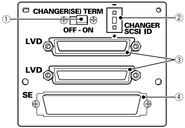
① SE SCSI termination switch (CHANGER)
Use to set changer's SCSI terminator ON/OFF. Factory default: ON
② SCSI ID switch (CHANGER)
Use to set the changer's SCSI ID. Pressing the upper protrusion causes the number to decrement, while pressing the lower protrusion increments the number. Factory default: 6
③ LVD SCSI interface connector
Connect using the supplied (or optionally purchased) SCSI Cable (LVD), or supplied SCSI Terminator (LVD).
④ SE SCSI interface connector
Connect to the changer's supplied SCSI Cable (SE).
Note:
Avoid touching the connectors, since faulty connection or damage from static electricity may result.
For connection information refer to the "SCSI Connection Manual" or consult your dealer.
Restrictions:
■ Connection Cable Length
LVD-side: 12 m or less
Total length of cables, including those inside the component (when multiple changers are connected, this includes the cables between the changers)
SE-side: 3 m or less
Total length of cable for each changer, including that internal to the component.
■ Connected Units
Total LVD and SE devices (including changers, but not including host bus adapters)
With one changer: 8 max*
With multiple changers: 15 max*
* The maximum permissible number of changers differs depending on the drive; for details consult your drive Operating Instructions.
Further, the total number of SE devices (including changers):
Regardless of the number of changers: 7 max (however, no more than 4 devices per changer)
* Due to restrictions on cable lengths, SE drives are to be installed in drive bays 1 – 3.
* SE devices should be given SCSI IDs of 0 – 6.
* This unit cannot be used together with Power supply unit DRM-PW701 due to drive installation limitations.
[Connection Example 1] With 1 Changer (LVD and SE drive installation)
| Changer | (SE) | x 1 |
| SE drive | (SE) | x 2 |
| LVD drive | (LVD) | x 2 |
| DRM-ULV16 | x 1 |
Changer internal cable length
Ⓐ LVD: About 0.25 m
⑧ LVD: About 0.7 m
© SE: About 0.6 m
(D) SE: About 0.5 m
Connection Cable Lengths
① CC-200 or CC-201 × 1☆
SCSI Cable (LVD): 2.5 m
② Accessory x 1
SCSI Cable (LVD): 0.55 m
③ DRM-LN721 x 1☆
LVD drive connector panel (for 2 drives)
④ Accessory x 1
SCSI Terminator (LVD)
⑤ Changer accessory x 1
SCSI Cable (SE): 0.35 m
☆: Option
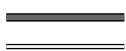
LVD Line: About 4.0 m
SE Line: About 1.45 m
Host
Host computer
flowchart
graph TD
    A["①"] --> B["②"]
    B --> C["③"]
    C --> D["④"]
    D --> E["LVD Drive 1"]
    E --> F["LVD Drive 2"]
    F --> G["SE Drive 1 (ON)*"]
    G --> H["SE Drive 1 (OFF)*"]
    H --> I["DRM-ULV16 card"]
    I --> J["Changer card (OFF)*"]
    style A fill:#f9f,stroke:#333
    style I fill:#ccf,stroke:#333
* SE device SCSI terminator switch setting
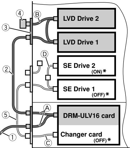
[Connection Example 2] With 1 Changer (LVD drive only)
Changer (SE) x 1
LVD drive (LVD) x 2
DRM-ULV16 x 1
Changer internal cable length
Ⓐ LVD: About 0.25 m
⑧ LVD: About 0.7 m
Connection Cable Lengths
① CC-200 or CC-201 x 1 ^☆ SCSI Cable (LVD): 2.5 m
② Accessory x 1
SCSI Cable (LVD): 0.55 m
③ DRM-LN721 x 1 ^☆ LVD drive connector panel (for 2 drives)
④ Accessory x 1
SCSI Terminator (LVD)
☆: Option
LVD Line: About 4.0 m
Host
flowchart
graph TD
    A["①"] --> B["②"]
    B --> C["③"]
    C --> D["④"]
    D --> E["LVD Drive 1"]
    D --> F["LVD Drive 2"]
    D --> G["DRM-ULV16 card"]
    G --> H["Changer card (ON) *"]
* SE device SCSI terminator switch setting
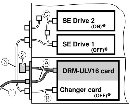
[Connection Example 3] With 1 Changer (SE drive only)
Changer (SE) x 1
SE drive (SE) x 2
DRM-ULV16 x 1
Changer internal cable length
Ⓐ LVD: About 0.25 m
⑧ SE: About 0.6 m
© SE: About 0.5 m
Connection Cable Lengths
① CC-200-8 or CC-201-8 x 1 ^☆ SCSI Cable (LVD): 8 m
② Accessory x 1
SCSI Terminator (LVD)
③ Changer accessory x 1
SCSI Cable (SE): 0.35 m
☆: Option
LVD Line: About 8.25 m
SE Line: About 1.45 m
Host
flowchart
graph TD
    A["SE Drive 1 (OFF)*"] --> B["DRM-ULV16 card"]
    C["SE Drive 2 (ON)*"] --> B
    D["Changer card (OFF)*"] --> B
    E["①"] --> F["②"]
    G["③"] --> H["④"]
    style A fill:#f9f,stroke:#333
    style C fill:#ccf,stroke:#333
    style D fill:#cfc,stroke:#333
    style E fill:#fcc,stroke:#333
    style F fill:#cff,stroke:#333
    style G fill:#ffc,stroke:#333
    style H fill:#fcf,stroke:#333
* SE device SCSI terminator switch setting
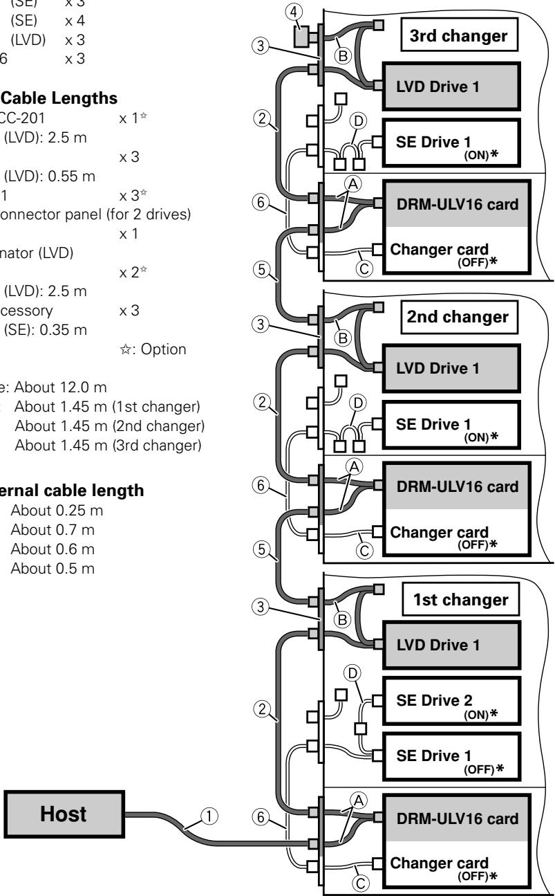
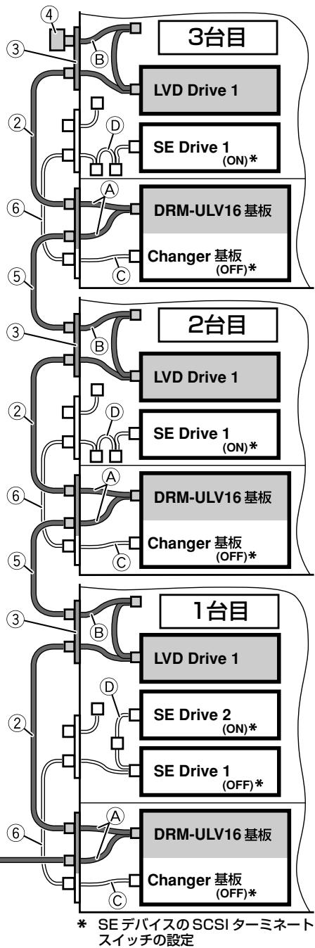
[Connection Example 4] With 3 Changers (daisy chain)
Changer (SE) x 3
SE drive (SE) x 4
LVD drive (LVD) x 3
DRM-ULV16 x 3
Connection Cable Lengths
LVD drive connector panel (for 2 drives)
④ Accessory x 1
SCSI Terminator (LVD)
⑤ CC-201 × 2☆
SCSI Cable (LVD): 2.5 m
⑥ Changer accessory x 3
SCSI Cable (SE): 0.35 m
☆: Option
LVD Line: About 12.0 m
—— SE Line: About 1.45 m (1st changer)
About 1.45 m (2nd changer)
About 1.45 m (3rd changer)
Changer internal cable length
Ⓐ LVD: About 0.25 m
(B) LVD: About 0.7 m
© SE: About 0.6 m
(D) SE: About 0.5 m
flowchart
graph TD
    A["Host"] -->|1| B["Internal cable length"]
    B -->|2| C["3rd changer"]
    B -->|3| D["2nd changer"]
    B -->|4| E["1st changer"]
    C --> F["LVD Drive 1"]
    C --> G["SE Drive 1 (ON)*"]
    D --> H["DRM-ULV16 card"]
    D --> I["Changer card (OFF)*"]
    E --> J["LVD Drive 1"]
    E --> K["SE Drive 1 (ON)*"]
    F --> L["SE Drive 2 (ON)*"]
    F --> M["SE Drive 1 (OFF)*"]
    G --> N["SE Drive 2 (ON)*"]
    G --> O["SE Drive 1 (OFF)*"]
    H --> P["SE Drive 2 (ON)*"]
    H --> Q["SE Drive 1 (OFF)*"]
    I --> R["SE Drive 2 (ON)*"]
    I --> S["SE Drive 1 (OFF)*"]
    J --> T["SE Drive 2 (ON)*"]
    J --> U["SE Drive 1 (OFF)*"]
    K --> V["SE Drive 2 (ON)*"]
    K --> W["SE Drive 1 (OFF)*"]
    L --> X["SE Drive 2 (ON)*"]
    L --> Y["SE Drive 1 (OFF)*"]
    M --> Z["SE Drive 2 (ON)*"]
    M --> AA["SE Drive 1 (OFF)*"]
    N --> AB["SE Drive 2 (ON)*"]
    N --> AC["SE Drive 1 (OFF)*"]
    O --> AD["SE Drive 2 (ON)*"]
    O --> AE["SE Drive 1 (OFF)*"]
    P --> AF["SE Drive 2 (ON)*"]
    P --> AG["SE Drive 1 (OFF)*"]
    Q --> AH["SE Drive 2 (ON)*"]
    Q --> AI["SE Drive 1 (OFF)*"]
    R --> AJ["SE Drive 2 (ON)*"]
    R --> AK["SE Drive 1 (OFF)*"]
    S --> AL["SE Drive 2 (ON)*"]
    S --> AM["SE Drive 1 (OFF)*"]
    T --> AN["SE Drive 2 (ON)*"]
    T --> AO["SE Drive 1 (OFF)*"]
    U --> AP["SE Drive 2 (ON)*"]
    U --> AQ["SE Drive 1 (OFF)*"]
    V --> AR["SE Drive 2 (ON)*"]
    V --> AS["SE Drive 1 (OFF)*"]
    W --> AT["SE Drive 2 (ON)*"]
    W --> AU["SE Drive 1 (OFF)*"]
    X --> AV["SE Drive 2 (ON)*"]
    X --> AW["SE Drive 1 (OFF)*"]
    Y --> AX["SE Drive 2 (ON)*"]
    Y --> AY["SE Drive 1 (OFF)*"]
    Z --> AZ["SE Drive 2 (ON)*"]
    Z --> BA["SE Drive 1 (OFF)*"]
* SE device SCSI terminator switch setting
[Interface]
| SE side | SCSI-2*1 | Amphenol 50-pin x 1 |
| LVD side | Ultra 160 SCSI*1 | Half-pitch 68-pin x 2 |
| *1: Transfer speed may differ depending on the devices connected. | ||
[Maximum cable connection length (including internal connection cables)]
| SE side : | 3 m *2 |
| LVD side : | 12 m *2 |
[Maximum units connectable]
| Total LVD and SE devices (including changers, but not including host bus adapters)15 *2*2: For SCSI cable and SCSI Terminator (LVD) use provided accessory or Pioneer-recommended product. |
[Other specifications]
| Power | DC +5 V, 0.7 A |
| Dimensions | |
| Body (internal changer dimension) | |
| 140.1 (W) x 117.2 (D) x 70.1 (H) mm | |
| Rear connectors (not including cables) | |
| 100.0 (W) x 40.2 (D) x 82.0 (H) mm | |
| Weight | 0.68 kg |
| Temperature during use (ambient changer temperature) | |
| +5 °C - +35 °C | |
| Humidity during use (ambient changer humidity) | |
| 5% - 85% (without condensation) | |
| Temperature during storage | |
| -40 °C - +60 °C | |
| Humidity during storage | |
| 5% - 90% (without condensation) | |
[Accessories]
| SCSI Terminator (LVD) | × 1 |
| SCSI Cable (LVD): 0.55 m | × 1 |
| ● Parts noted below are used when connecting to changer | |
| Connector Ass'y | × 2 |
| Screws | × 4 |
| Posts | × 2 |
| Cushion | × 1 |
| Edge guard | × 1 |
| Cable binders | × 3 |
■ To assure optimum performance, use only SCSI Cables and SCSI Terminator (LVD) provided as accessories or those recommended by Pioneer.
■ The specifications and design of this product are subject to change without notice, due to improvement.
(SE = Single-Ended SCSI LVD: Low-Voltage Differential SCSI)
(SE:Single-ended SCSI LVD: Low Voltage Differential SCSI)
flowchart
graph LR
    A["Host"] --> B
    B --> C["1"]
flowchart
graph TD
    A["3台目"] --> B["LVD Drive 1"]
    A --> C["SE Drive 1 (ON)*"]
    D["2台目"] --> E["DRM-ULV16 基板"]
    D --> F["Changer 基板 (OFF)*"]
    G["1台目"] --> H["LVD Drive 1"]
    G --> I["SE Drive 2 (ON)*"]
    G --> J["SE Drive 1 (OFF)*"]
    K["3台目"] --> L["DRM-ULV16 基板"]
    K --> M["Changer 基板 (OFF)*"]
    N["2台目"] --> O["DRM-ULV16 基板"]
    N --> P["Changer 基板 (OFF)*"]
    Q["1台目"] --> R["DRM-ULV16 基板"]
    Q --> S["Changer 基板 (OFF)*"]
    T["3台目"] --> U["LVD Drive 1"]
    T --> V["SE Drive 1 (ON)*"]
    W["2台目"] --> X["DRM-ULV16 基板"]
    W --> Y["Changer 基板 (OFF)*"]
    Z["1台目"] --> AA["LVD Drive 1"]
    Z --> AB["SE Drive 2 (ON)*"]
    AC["2台目"] --> AD["DRM-ULV16 基板"]
    AC --> AE["Changer 基板 (OFF)*"]
    AF["3台目"] --> AG["LVD Drive 1"]
    AF --> AH["SE Drive 2 (ON)*"]
    AI["2台目"] --> AJ["DRM-ULV16 基板"]
    AI --> AK["Changer 基板 (OFF)*"]
140.1 (幅)×117.2 (奥行き)×70.1 (高さ) mm
リア端子部(ケーブル部を除く)
100.0 (幅)×40.2 (奥行き)×82.0 (高さ) mm
質量
0.68 kg
動作温度(チェンジャーの外部環境温度)
+5 ℃ \~ +35 ℃
動作湿度(チェンジャーの外部環境湿度)
5%~85%(結露のないこと)
保存温度
-40℃\~+60℃
保存湿度
5%~90%(結露のないこと)
【付属品】
AFTER-SALES SERVICE FOR PIONEER PRODUCTS
Please contact the dealer or distributor from where you purchased the product for its after-sales service (including warranty conditions) or any other information. In case the necessary information is not available, please contact the Pioneer's subsidiaries (regional service headquarters) listed below:
PLEASE DO NOT SHIP YOUR PRODUCT TO THE COMPANIES at the addresses listed below for repair without advance contact, for these companies are not repair locations.
AMERICA
PIONEER ELECTRONICS (USA) INC.
CUSTOMER SUPPORT DIVISION
P.O. BOX 1760, LONG BEACH, CA 90801-1760, U.S.A.
EUROPE
PIONEER EUROPE NV
EUROPEAN SERVICE DIVISION
HAVEN 1087, KEETBERGLAAN 1, B-9120 MELSELE, BELGIUM
ASEAN
PIONEER ELECTRONICS ASIACENTRE PTE. LTD.
SERVICE DEPARTMENT
253, ALEXANDRA ROAD #04-01 SINGAPORE 159936
JAPAN AND OTHERS
PIONEER CORPORATION (HEAD OFFICE)
CUSTOMER SUPPORT CENTER
Published by Pioneer Corporation.
Copyright © 2004 Pioneer Corporation.
All rights reserved.
パイオニア株式会社
PIONEER ELECTRONICS (USA) INC.
Business Solutions Division: 2265 East 220th Street, Long Beach, CA 90810, U.S.A. TEL: +1-213-746-6337
Customer Support Division: 1925 East Dominguez St. Long Beach, CA 90810, U.S.A. TEL: +1-310-952-3076
PIONEER EUROPE NV
Multimedia Division: PIONEER House, Hollybush Hill Stoke Poges, Slough SL2 4QP U.K. TEL: +44-1753-789-789
PIONEER ELECTRONICS OF CANADA, INC.
Industrial Products Department: 300 Allstate Parkway, Markham, Ontario L3R OP2, Canada TEL: +1-905-479-4411
PIONEER ELECTRONICS AUSTRALIA PTY. LTD.
178-184 Boundary Road, Braeside, Victoria 3195, Australia TEL:+61-39-586-6300
PIONEER ELECTRONICS ASIACENTRE PTE. LTD.
253 Alexandra Road, #04-01, Singapore 159936 TEL: +65-6472-1111
PIONEER HIGH FIDELITY TAIWAN CO., LTD.
13 ^th Fl., No.44 Chung Shan, North Road Section 2 Taipei, Taiwan TEL: +886-2-2521-3588
日本先锋公司
日本国东京都目黒区目黒1-4-1
经销商:先锋电子(中国)投资有限公司
- IMPORTANT
- CAUTION
- RISK OF ELECTRIC SHOCK DO NOT OPEN
- CAUTION:
- WARNING
- AVERTISSEMENT
- Information to User
- [For Taiwanese model]
- 警告使用者:
- FOR ENGLAND
- FOR FRANCE
- Attention
- Note:
- Features
- Precautions in Use
- Nomenclature
- Rear Connectors
- Restrictions:
- ■ Connection Cable Length
- LVD-side: 12 m or less
- SE-side: 3 m or less
- ■ Connected Units
- Total LVD and SE devices (including changers, but not including host bus adapters)
- Further, the total number of SE devices (including changers):
- [Connection Example 1] With 1 Changer (LVD and SE drive installation)
- Changer internal cable length
- Connection Cable Lengths
- [Connection Example 2] With 1 Changer (LVD drive only)
- Host
- [Connection Example 3] With 1 Changer (SE drive only)
- [Connection Example 4] With 3 Changers (daisy chain)
- 【付属品】
- AFTER-SALES SERVICE FOR PIONEER PRODUCTS
- AMERICA
- EUROPE
- ASEAN
- JAPAN AND OTHERS
- パイオニア株式会社
- PIONEER ELECTRONICS (USA) INC.
- PIONEER EUROPE NV
- PIONEER ELECTRONICS OF CANADA, INC.
- PIONEER ELECTRONICS AUSTRALIA PTY. LTD.
- PIONEER ELECTRONICS ASIACENTRE PTE. LTD.
- PIONEER HIGH FIDELITY TAIWAN CO., LTD.
- 日本先锋公司
- 经销商:先锋电子(中国)投资有限公司
Brand : PIONEER
Model : DRM-ULV16
Category : Computer Interface