
DRM-7000 - DVD player PIONEER - Free user manual and instructions
Find the device manual for free DRM-7000 PIONEER in PDF.
| Product Type | Disc changer (disc library) |
| Brand | Pioneer |
| Model | DRM-7000 |
| Maximum disc capacity | 720 discs (12 cm) |
| Maximum number of magazines | 14 magazines of 50 discs + 1 hyper magazine of 20 discs |
| Maximum number of installable drives | 16 |
| Power supply | AC 100-240 V, 50/60 Hz |
| Maximum power consumption | 5.5 A (500 W) |
| Dimensions (W x D x H) | 760 x 795 x 1520 mm (with mounting brackets) |
| Weight (main unit) | 91.7 kg |
| Operating temperature | +5 °C to +35 °C |
| Operating humidity | 5 % to 85 % (non-condensing) |
| Interface | SCSI |
| Display | LCD window 2 lines x 16 characters |
| Security | Key lock, System Administrator mode |
| Offline media management | Yes, with internal memory magazines and identification code |
| Magazine types | 50 discs (normal or lockable type), extractable 20-disc hyper magazine |
| Included accessories | 20-disc hyper magazine, SCSI cable, power cable, stabilizers, unlock keys |
| Maintenance and cleaning | Soft dry cloth, diluted mild detergent (1:5), no volatile solvents |
| Repairability | Entrust to qualified personnel, spare parts available through Pioneer after-sales service |
Frequently Asked Questions - DRM-7000 PIONEER
User questions about DRM-7000 PIONEER
0 question about this device. Answer the ones you know or ask your own.
Ask a new question about this device
Download the instructions for your DVD player in PDF format for free! Find your manual DRM-7000 - PIONEER and take your electronic device back in hand. On this page are published all the documents necessary for the use of your device. DRM-7000 by PIONEER.
USER MANUAL DRM-7000 PIONEER
Operating Instructions
Mode d'emploi
Bedienungsanleitung
操作说明书
取扱説明書
IMPORTANT
The lightning flash with arrowhead symbol, within an equilateral triangle, is intended to alert the user to the presence of uninsulated "dangerous voltage" within the product's enclosure that may be of sufficient magnitude to constitute a risk of electric shock to persons.
CAUTION
RISK OF ELECTRIC SHOCK DO NOT OPEN
CAUTION:
TO PREVENT THE RISK OF ELECTRIC SHOCK, DO NOT REMOVE COVER (OR BACK). NO USER-SERVICEABLE PARTS INSIDE. REFER SERVICING TO QUALIFIED SERVICE PERSONNEL.

The exclamation point within an equilateral triangle is intended to alert the user to the presence of important operating and maintenance (servicing) instructions in the literature accompanying the appliance.
H002 En
Replacement and mounting of an AC plug on the power supply cord of this unit should be performed only by qualified service personnel.
IMPORTANT
FOR USE IN THE UNITED KINGDOM.
The wires in this mains lead are coloured in accordance with the following code :
Green and Yellow : Earth
Blue : Neutral
Brown : Live
If the plug provided is unsuitable for your socket outlets, the plug must be cut off and a suitable plug fitted.
The cut-off plug should be disposed of and must not be inserted into any 13 amp socket as this can result in electric shock. The plug or adaptor or the distribution panel should be provided with 5 A fuse. As the colours of the wires in the mains lead of this appliance may not correspond with coloured markings identifying the terminals in your plug, proceed as follows;
The wire which is coloured green and yellow must be connected to the terminal in the plug which is marked with the letter E or by the earth symbol ⊕, or coloured green or green and yellow.
The wire which is coloured blue must be connected to the terminal which is marked with the letter N or coloured black.
The wire which is coloured brown must be connected to the terminal which is marked with the letter L or coloured red.
NOTE
After replacing or changing a fuse, the fuse cover in the plug must be replaced with a fuse cover which corresponds to the colour of the insert in the base of the plug or the word that is embossed on the base of the plug, and the appliance must not be used without a fuse cover. If lost replacement fuse covers can be obtained from: your dealer.
Only 5 A fuses approved by B.S.I. or A.S.T.A to B.S. 1362 should be used. H004BEn
[FOR EUROPEAN AND U.K. MODELS]
CAUTION
This product contains a laser diode of higher class than 1. To ensure continued safety, do not remove any covers or attempt to gain access to the inside of the product.
Refer all servicing to qualified personnel.
The following caution label appears on your changer.
Location: rear of the changer
CLASS 1 LASER PRODUCT LASER KLASSE 1 APPAREIL À LASER DE CLASSE 1
WARNING!
CAUTION : USE OF CONTROLS OR ADJUSTMENTS OR PERFORMANCE OF PROCEDURES OTHER THAN THOSE SPECIFIED HEREIN MAY RESULT IN HAZARDOUS RADIATION EXPOSURE,
CAUTION : THE USE OF OPTICAL INSTRUMENTS WITH THIS PRODUCT WILL INCREASE EYE HAZARD.
H013 En
[For U.S. model]
CAUTION:
This product satisfies FCC regulations when shielded cables and connectors are used to connect the unit to other equipment. To prevent electromagnetic interference with electric appliances such as radios and televisions, use shielded cables and connectors for connections.
[For Canadian model]
This Class A digital apparatus complies with Canadian ICES-003.
This product complies with the Low Voltage Directive (73/23/EEC), EMC Directives (89/336/EEC, 92/31/EEC) and CE Marking Directive (93/68/EEC).
FOR FRANCE
Alteration or modifications carried out without appropriate authorization may invalidate the user's right to operate the equipment. H011 En
FOR ENGLAND
Warning
This is a class A product. In a domestic environment this product may cause radio interference in which case the user may be required to take adequate measures.
FOR FRANCE
Attention
NOTE: This equipment has been tested and found to comply with the limits for a Class A digital device, pursuant to Part 15 of the FCC Rules. These limits are designed to provide reasonable protection against harmful interference when the equipment is operated in a commercial environment. This equipment generates, uses, and can radiate radio frequency energy and, if not installed and used in accordance with the instruction manual, may cause harmful interference to radio communications. Operation of this equipment in a residential area is likely to cause harmful interference in which case the user will be required to correct the interference at his own expense. H061 En
[For Taiwanese model]
Handling the cord on this product or cords associated with accessories sold with the product will expose you to lead, a chemical known to the State of California and other governmental entities to cause cancer and birth defects or other reproductive harm.
Wash hands after handling
[For Korean model]
IMPORTANT! SAFETY INSTRUCTIONS
- READ INSTRUCTIONS – All the safety and operating instructions should be read before the appliance is operated.
- RETAIN INSTRUCTIONS – The safety and operating instructions should be retained for future reference.
- HEED WARNING – All warnings on the appliance and in the operating instructions should be adhered to.
- FOLLOW INSTRUCTIONS – All operating and use instructions should be followed.
- CLEANING – Unplug this product from the wall outlet before cleaning.
Do not use liquid cleaners or aerosol cleaners. Use a damp cloth for cleaning. - WATER AND MOISTURE – Do not use this product near water.
- ACCESSORIES – Do not place this product on an unstable cart, stand, or table. The product may fall and be seriously damaged.
- VENTILATION – Slots and openings in the cabinet and back or bottom are provided for ventilation and to ensure reliable operation of the product and to protect it from overheating. These openings must not be blocked or covered. They should never be blocked by placing the product on a bed, sofa, rug, or other similar surface. This product should never be placed in a built-in installation unless proper ventilation is provided.
- POWER SOURCES – This product should be operated only from the type of power source indicated on the marking label. If you are not sure of the type of power available, consult your dealer or local power company.
-
PLUG – This product is equipped with a wired grounding-type plug (a plug having a third (grounding) pin). This plug will only fit into a grounding type power outlet. This is a safety feature. If you are unable to insert the plug fully into the outlet, contact your electrician to replace your obsolete outlet. Do not defeat the safety purpose of the grounding type plug.
-
POWER-CORD PROTECTION – When unplugging the apparatus, pull on the plug – not on the cord. Do not handle the cord on plug with wet hands. Doing so could cause an electric short or shock. Do not allow anything to rest on the power cord. Do not locate this product where persons will walk on the cord.
-
OVERLOADING – Do not overload wall outlets and extension cords as this can result in fire or electric shock.
-
OBJECT AND LIQUID ENTRY – Never push objects of any kind into this product through openings as they may touch dangerous voltage points or short out parts that could result in a fire or electric shock. Never spill liquid of any kind on the product.
-
CONDENSATION – Moisture will form in the operating section of the product and the product's performance will be impaired if the product is brought from cool surroundings into a warm room or if the room temperature rises suddenly. To prevent this, let the product stand in its new surroundings for about an hour or two before switching it on, or ensure that the room temperature rises gradually.
-
SERVICING – Do not attempt to service this product yourself as opening or removing covers may expose you to dangerous voltage or other hazards. Refer all servicing to qualified service personnel.
16. DAMAGE REQUIRING SERVICE
Unplug this product from the wall outlet and refer servicing to qualified service personnel under the following conditions:
a. When the power cord or plug is damaged.
b. If liquid has been spilled, or objects have fallen into the video product.
c. If the product has been exposed to rain or water.
d. If the product does not operate normally when the operating instructions are followed. Adjust only those controls that are covered by the operating instructions. Improper adjustment of other controls may result in damage and will often require extensive work by a qualified technician to restore the product to its normal operation.
e. If the product has been dropped or the cabinet has been damaged.
f. When the product exhibits a distinct change in performance – this indicates a need for service.
WARNING: THE APPARATUS IS NOT WATERPROOFS, TO PREVENT FIRE OR SHOCK HAZARD, DO NOT EXPOSE THIS APPARATUS TO RAIN OR MOISTURE AND DO NOT PUT ANY WATER SOURCE NEAR THIS APPARATUS, SUCH AS VASE, FLOWER POT, COSMETICS CONTAINER AND MEDICINE BOTTLE ETC. H001BEn
WARNING: THIS PRODUCT EQUIPPED WITH A THREE-WIRE GROUNDING (EARTHING) TYPE PLUG, A PLUG HAVING A THIRD (GROUNDING, EARTHING) PIN, IT WILL ONLY FIT INTO A GROUNDING (EARTHING) TYPE POWER OUTLET. THIS IS A SAFETY FEATURE. IF YOU ARE UNABLE TO INSERT THE PLUG INTO THE OUTLET, CONTACT YOUR ELECTRICIAN TO REPLACE YOUR OBSOLETE OUTLET. DO NOT DEFEAT THE SAFETY PURPOSE OF THE GROUNDING (EARTHING) TYPE PLUG. H043A En
Operating Environment
H045 En
Operating environment temperature and humidity:
+5 °C - +35 °C (+41 °F - +95°F); less than 85 %RH (cooling vents not blocked)
Do not install in the following locations
- Location exposed to direct sunlight or strong artificial light
- Location exposed to high humidity, or poorly ventilated location
[For Australian and New Zealander models]
Warning
This is a class A product. In a domestic environment, this product may cause radio interference in which case the user may be required to take adequate measure. H062A E
For pluggable Equipment, The Socket-Outlet Shall Be Installed Near The Equipment and Shall Be Easily Accessible.
The Generation of Acoustical Noise Is Less Than 70 dB. (ISO 7779/DIN45635)
Thank you for buying this Pioneer product.
Please read through these operating instructions so you will know how to operate your model properly. After you have finished reading the instructions, put them away in a safe place for future reference.
In some countries or regions, the shape of the power plug and power outlet may sometimes differ from that shown in the explanatory drawings. However, the method of connecting and operating the unit is the same.
CONTENTS
FEATURES 5
HANDLING PRECAUTIONS ...... 6
READ BEFORE USE ....7
Security features 7
Offline media management .... 7
Deciding on system configuration 8
Add-on products 8
Items included 10
Discs 11
TO AVOID PROBLEMS ...... 12
NAMES AND FUNCTIONS OF
INDIVIDUAL PARTS ...... 14
INSTALLATION 16
OPERATION 24
User mode 24
System administrator mode 24
Adding drive units 38
Exchanging drive units 41
OTHERS 44
Troubleshooting 44
Specifications 46
FLEXIBLE UNIT DESIGN
The Pioneer DRM-7000/DRM-3000-disc changer is designed so that a variety of different components may be purchased and installed together to meet a variety of different needs.
The Pioneer DRM-7000/DRM-3000 comes with bays (i.e., spaces for the installation of drives or 50-disc magazines) located at the front and rear of the unit, and the bays are fitted with access doors that are designed to open widely and enable you to install or remove individual components with ease.
The front bay is for exclusive use with 50-disc magazines; the rear bay has been designed as a multi-purpose installation area:
Loading Capacity
| DRM-7000 | DRM-3000 | |
| Front bay50-disc magazines only | 7 | 3 |
| Rear bayComponent50-disc magazines | Max 16Max 7 | Max 8Max 3 |
The maximum number of optional components that can be installed differs depending on the component involved; for details, consult the operating instructions for your option components.
Combined Example
| DRM-7000 | DRM-3000 | |
| Data capacity emphasis | Drives 2 | Drives 2 |
| Discs 720 | Discs 320 | |
| Performance emphasis | Drives 16 | Drives 8 |
| Discs 370 | Discs 170 |
If desired, you can start with empty bay spaces and add devices to them as your requirements increase.
THREE DIFFERENT TYPES OF DISC MAGAZINES EQUIPPED WITH INTERNAL MEMORY
Pioneer provides three different types of disc magazines designed for convenience and ease of use in different applications.
20-disc hyper magazine:
The main feature of the hyper magazine is its mobility. It can be inserted and removed without opening the access door. Another feature is a smart memory system that records all user operations toward its lock/unlock mechanism. One hyper magazine is provided as a standard equipment with each Pioneer DRM-7000/DRM-3000.
50-disc magazine (locked-type):
This model is perfect for managing offline media where the security and unchangeableness may be required. Built-in locking mechanism makes it impossible to remove discs from magazine whenever it is outside the changer.
50-disc magazine (normal-type):
This model is convenient for importing or exporting large volumes of discs into or from the changer. You can insert discs into or remove them from a magazine releasing the locking mechanism by a knob fitted with this magazine when it is outside the changer.
EASE OF INSTALLATION
In order to connect the changer to an existing data management system or to build a new data management system, it is necessary for the host computer to be able to properly identify the changer and all the drives contained therein and it is necessary to attach all the cables and specify the settings needed for the host computer to control the changer and drives.
The Pioneer DRM-7000/DRM-3000 is designed not only to make it easy to install and add new drives, but also with a wide range of features designed to make it easier to specify host computer settings.
SECURITY FEATURES DESIGNED TO PREVENT ERRONEOUS OR UNAUTHORIZED OPERATIONS
In order to prevent interference, conflicts, or clashes occurring between manual operations and computer-based operations, entering procedure to the system administrator mode is introduced. Anyone who wants to perform operations from the control panel is required to enter system administrator mode first, using the provided lock release key. And it is possible to prevent the switchover to some sub-modes by issuing a command from the host computer.
It is also possible to assign security privileges on the system administrator who has the lock release key. Then operations directly manipulating discs, like opening mailslot and ejecting hyper magazine, are permitted to only the system administrator.
CONTROL PANEL FITTED WITH AN LCD MESSAGE WINDOW FOR EASE OF USE
The control panel is fitted with a 2-line, 16-column LCD message window which is used to display instructions on the proper operations to perform. And this makes it possible to perform any of the wide variety of different operations provided by the DRM-7000/DRM-3000 with only 5 keys.
INSTALLATION
Select an installation site with a flat, solid surface.
Do not install the system where it will suffer any of the following:
① Exposure to direct sunlight or a heater
② High humidity or dust
③ Proximity to bathroom or kitchen
④ Exposure to spotlight
⑤ Proximity to any large electric apparatus such as a refrigerator, air conditioner, dimmer, etc.
⑥ Uneven or unsteady installation surface.
(If the surface is not flat, first put down a hard plate or similar support so that the system is installed level.)
⑦ Difficulty of service and maintenance.
If the changer is to be installed next to a wall, a minimum of at least 50 cm of space must be provided between the back of the changer and the wall.
Avoid placing objects directly on the changer.
HANDLING PRECAUTIONS
- Be careful not to stain, scratch or leave fingerprint, etc., on the signal surface, or recording surface of the discs. The specified playback performance or recording performance may not be obtained with such discs.
- Do not insert more than one disc in a mailslot, otherwise malfunction will result.
- The Changer does not manage the disc contents. The data should be managed by involving the host.
- Use only recording discs recommended by Pioneer. The specified recording performance or playback performance may not be obtained if a non-recommended disc is used. Please note that the data recorded on discs is not covered by our warranty.
- Pioneer may not be held liable for the loss of any data or any other direct or indirect damage suffered as the result of the use or breakdown of this product. It is strongly recommended that regular backups be taken of all critical data.
- Please be careful not to lose the lock release keys provided with your DRM-7000/DRM-3000, otherwise you could not manage your changer any more. The lock release key certifies you as a system administrator and gives you a privilege to open access doors, to eject a hyper magazine and to use a mailslot.
POWER-CORD CAUTION
Handle the power cord by the plug. Do not pull out the plug by tugging the cord and never touch the power cord when your hands are wet as this could cause a short circuit or an electric shock. Do not place the unit, a piece of furniture, etc., on the power cord, or pinch the cord. Never make a knot in the cord or tie it with other cords. The power cords should be routed such that they are not likely to be stepped on. A damaged power cord can cause a fire or give you an electrical shock. Check the power cord once in a while. When you find it damaged, ask your nearest PIONEER authorized service center or your dealer for a replacement.
FOR SAFETY
- Do not install the unit on any unsteady platform or desk, etc., as the unit is tall and heavy.
- Do not stack the units or do not place a heavy object on the unit. It is extremely dangerous to do this, because the objects may fall off or the unit may topple over. (Any damage or injury suffered as a result of such installation is the sole responsibility of the user.)
- Attach the placement fixtures first after unpacking the changer. If it is moved before they are attached, there is a danger of it toppling over or of the cables on the rear being damaged.
- Always be sure not to insert your hand into the 20-disc hyper magazine bay or not to touch any parts inside of the bay when the power has been turned on, otherwise it may result in bodily injury.
- The Changer can accommodate only the discs with a diameter of 12cm (5in). As the Changer detects the presence of disc with optical detection of the position at about 5mm (3/16in) inside the external periphery of the 12cm (5in) disc, the use of a disc which is transparent at the corresponding position or a 8cm (3in) disc may lead to disc detection error and to the disc damage in the worst case. Also, the use of a 8cm disc adapter is strictly prohibited.
- For safety reasons, the DRM-7000/DRM-3000 is designed so that the access doors cannot be opened while the changer mechanism or internal drives are in operation.
- The high speed rotation of discs or the operation of the high speed disc transport mechanism in the DRM-7000/DRM-3000 causes slight vibrations and noise, but this does not indicate a problem. And it does not effect the performance of the changer.
CONDENSATION
If the temperature difference between the changer and environment is too large, water will condense in the changer and the system may not provide proper performance. For example, if you bring the changer into a warm room from outside in cold weather, or if you increase room temperature abruptly, condensation may result. If condensation occurs, leave the changer for one hour in the room, or increase room temperature gradually before using it.
CLEANING THE CHANGER
To clean the panel and the cover, use a soft, dry cloth to wipe off dust and dirt. If the cabinet is heavily soiled, wipe off the dirt using a soft cloth soaked with neutral detergent diluted 5 to 6 times. Then wipe the water off with a dry cloth. Do not use benzine, thinner, insecticide or similar volatile chemicals, as they may dissolve or discolor the cabinet surface. If you use a chemical polishing cloth, carefully read the instructions supplied with it.
SECURITY FEATURES
Information on the location of discs within the changer and information to access data on discs are strictly monitored and controlled from the changer control software and the upper-level database management software.
Because of this, if any changes in the status of the discs within the changer occur at a time when the changer is not under the control of the host computer (or in a network environment, under the control of a server), it becomes impossible to control the changer and drives and to read necessary files from discs.
Allowing discs stored within the changer to be removed without any restrictions poses a security risk, not only in that it would become impossible to access discs which have been removed but also in that it might lead to the damage or loss of discs.
Although the DRM-7000/DRM-3000 has been designed so as to open the front and rear access doors from the control panel (located at the top of the front of the unit) to remove magazines or to insert or remove discs through the mailslots, anyone who considers the security issues noted above will be able to understood that it is necessary to place restrictions on such operations.
This is why the control panel of the DRM-7000/DRM-3000 has been fitted with a key switch which may be locked to disable operations of control keys. This switch cannot be unlocked without the key provided with the DRM-7000/DRM-3000, and if the system administrator will always keep this key, it is impossible that ordinary users without key perform unauthorized operations from the control panel.
It is also possible to restrict the range of operations which are performed from the control panel. It means that a part of system administrator's privileges is controlled by the command issued from the host computer and even if a system administrator has the key, the host computer makes it impossible to open the access doors, exchange discs, or perform other unfavorable operations for itself.
OFFLINE MEDIA MANAGEMENT
The DRM-7000/DRM-3000 provides the following features which makes it perfect for the management of offline media.
● Removable disc magazines
Disc magazines may be removed from the changer with the discs left in the magazines. The use efficiency of the space within the changer may much improve if the infrequently used discs are collected in one magazine and it is taken out from the changer into the offline storage.
● Unique disc magazine IDs
All disc magazines used in the DRM-7000/DRM-3000 are assigned unique ID codes which makes it possible to identify individual magazines simply by inserting them into the magazine bays.
All of the discs within an inserted magazine become available immediately no matter which magazine bay it is inserted into as long as the discs installed in the magazine have been registered in the database as corresponding to the magazine ID in question, and the same holds true when a magazine is inserted into a different changer as long as the changer in which it is inserted is under the control of the same database.
● Disc magazines designed for easy tracking and control
Removing, inserting or replacing discs in magazines after they have been removed from a changer may destroy the correspondence between discs and magazine IDs.
To solve this problem, Pioneer provides 50-disc magazine which has a locking mechanism to prevent all attempt to change the status of the magazine outside the changer and hyper magazine which has a smart memory system that records all user operations toward its lock/unlock mechanism so as to make it easier to track and control the use of offline media.
● Registration of changer ID
When a disc magazine has been inserted into a changer not under the control of the database management software or into a changer belonging to another system, the discs within that magazine may be rewritten or may be replaced with other discs within that changer. Even if the magazine in question is a locked-type, these discrepancies between the discs actually contained within the magazine and the information on those discs stored in the database may be arise.
In order to prevent such problems from occurring, disc magazines are designed to record the ID of the changer in which they are used, and as long as the database has a list of the IDs of changers controlled under the given database, it is possible for the database management software to determine whether or not a inserted disc magazine has to be reinstalled by checking the changer ID that may be read with the magazine ID.
However although the DRM-7000/DRM-3000 changer and disc magazines do provide the features needed for the management of offline media, it should be noted that the actual procedures and methods available for the management of offline media may differ depending on the database management software and changer control software being used.
It should further be noted that it is necessary to establish how to employ controls for the handling of offline media. In fact if management controls are strict enough, it is even possible to use normal-type disc magazines which would ordinarily be unsuited for use in the management of offline media, in the same way as one would use locked-type disc magazines.
DECIDING ON SYSTEM CONFIGURATION
Before installing or using the changer, the first thing which has to be done is to decide what components you should install to where of the changer.
The connector panel and SCSI cables which come with the DRM-7000/DRM-3000 are prepared on the assumption of the following system configuration:
■ Two drives
■ Both drives will be connected internally with multi drive connector panel and the provided changer/drive SCSI cable is used to connect the drive SCSI ports to the changer SCSI ports
(Note that it is also necessary to purchase another SCSI cable to connect the changer to the host computer when the DRM-7000/DRM-3000 is to be used in the above configuration.)
If you wish to install three or more drives or to use more than one SCSI bus to increase data transfer speeds, it will be necessary to purchase additional connector panels and SCSI cables.
To determine what additional equipment must be purchased in order to create a desired configuration, it is recommended that you first decide where drives are to be installed and consult the configuration sheet on p. 225 (DRM-7000) or p. 226 (DRM-3000) before actually trying to configure your system.
Before actually beginning to configure your changer system, it is absolutely necessary that the following items be determined:
- The types and numbers of drives to be installed and where they are to be installed. (An additional power unit is necessary when installing 9 or more drives on the DRM-7000).
- The positions where connector panels are to be attached. (Note that the DRM-7000/DRM-3000 comes equipped with a multi drive connector panel and if you need single drive connector panels you must purchase them.)
- The SCSI IDs to be assigned to each of the drives to be installed. (Note that it is impossible to assign the same SCSI ID to two or more drives on the same SCSI bus.)
- The connecting plan of the cables running between individual drives and connector panels.
- Which drives are to be terminated (i.e., the drive's termination switch of the terminal drive in each SCSI chain is to be turned on).
An example of how SCSI cables should be connected is shown on p. 19.
The power unit provided as standard equipment is capable of supplying power to rear bays #1 – 8. The total power consumed by these eight drives should not exceed the following:
DC +5 V 12 A or less
DC +12 V 8 A or less
The maximum current capacity of a single connector is as follows:
DC +5 V Max 4 A
DC +12 V Max 4 A
By adding an optional expansion power unit to the DRM-7000, power can be supplied to rear bays #9 – 16.
The maximum power consumption of these upper bays and the maximum amount of power which may be supplied over a single connector is the same as that of the lower bays (i.e., Bay #1 – Bay #8).
NOTE:
- Be sure never to use any add-on products other than Pioneer products.
- When turning off the power and turning it back on, always be sure to allow an interval of 10 seconds or more to elapse after turning off the power before turning it back on. Note that this must be done because there are times when the power is not switched off immediately even after the power switched has been flipped off when few drives have been installed in the changer.
ADD-ON PRODUCTS
The following components may be purchased separately for use with the Pioneer DRM-7000/DRM-3000 in order to adapt it for use in configuring a system to your own specifications. The maximum number of optional components that can be installed differs depending on the component involved; for details, consult the operating instructions for your option components.
50-disc magazine
Used to store discs within the changer, these magazines come in both normal and locked types which can be installed in whatever combination best fits your needs.
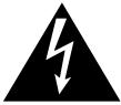
● 50-disc magazine (locked-type) [DRM-AL751]
natural_image
Technical line drawing of a mechanical component with layered structure and mounting holes (no text or symbols)These disc magazines are designed so that the lock is not released even when a magazine is removed from a changer. Therefore the mailslot is necessary to insert discs into these magazines or remove discs from them. These magazines are extremely effective for use in situations where they are used in combination with a host computer which supports offline media management. (See p. 7 for further details.)
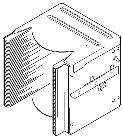
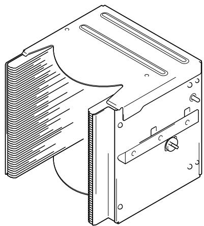
● 50-disc magazine (normal-type) [DRM-AF751]
natural_image
Technical line drawing of a mechanical housing or enclosure with heat dissipation and mounting brackets (no text or symbols)Fitted with a knob which is used to release the locking mechanism, these magazines are convenient for importing or exporting large volumes of discs into or from the changer.
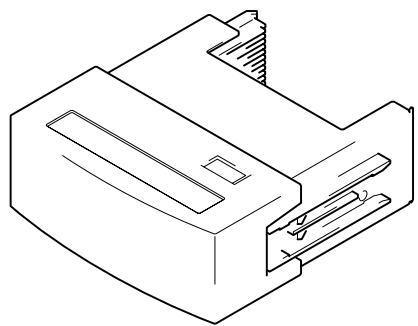
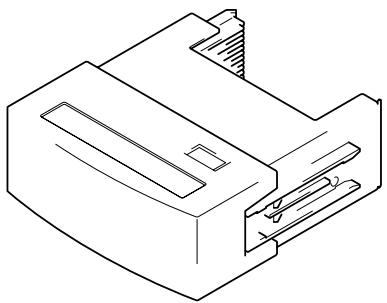
20-disc hyper magazine [DRM-AH721]
natural_image
Isometric line drawing of a mechanical component or housing (no text or symbols)This magazine is designed to make it possible to insert or remove without opening the access doors. This magazine is also equipped with a smart memory system that records all user operations toward its lock/unlock mechanism. Therefore the hyper magazine is convenient and also perfect for the management of offline media. The DRM-7000/DRM-3000 comes with a hyper magazine as a standard equipment, and additional hyper magazines may be used to easily build up an offline library in 20-disc units.
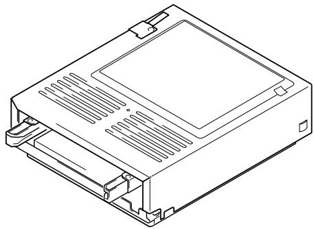
DVD-R/RW drive unit [DVD-R7322]
Power consumption: DC +5V, 1.5A DC +12V, 1.0A
natural_image
Line drawing of a computer case chassis with ventilation slots and drive bays (no text or symbols)The DVD-R7322 internal DVD-R/RW drive unit may be used both to read ordinary DVD-ROM discs and to read from and write to DVD-R/RW discs.
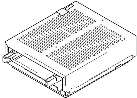
DVD-ROM drive unit [DVD-D7563]
Power consumption: DC +5V, 1.0A DC +12V, 1.0A
natural_image
Technical line drawing of a rectangular electronic device with ventilation slots and mounting brackets (no text or symbols)The DVD-D7563 internal DVD-ROM drive unit may be used to read DVD-ROM discs.
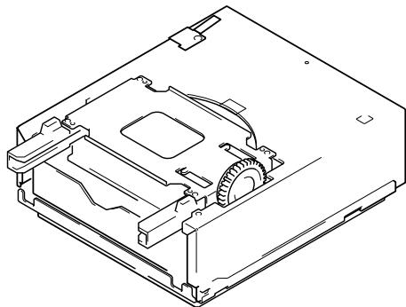
Disc flip unit [DRM-UF701]
natural_image
Technical line drawing of a mechanical device with internal components (no text or symbols)The DRM-UF701 disc flip unit is designed for use in turning over a disc. Note that this component is required when using double-sided DVD discs.
Power supply unit [DRM-PW701] (for DRM-7000)
A DRM-PW701 add-on power supply unit must be installed in order to use 9 or more drives within the same changer. Always be sure to contact Pioneer service personnel for installation.
Power supply: Maximum of DC +5V, 12A
Maximum of DC +12V, 8A
Malti drive connector panel [DRM-SN721]
The DRM-SN721 multi drive connector panel comes with a cable which may be used to connect two internal drives. The DRM-7000/DRM-3000 comes with a DRM-SN721 panel as a standard equipment, and this panel may be used to connect 2 or 4 additional drives in a daisy chain.
Single drive connector panel [DRM-SN711]
The DRM-SN711 single drive connector panel is used when a drive is to be connected directly to a host computer or when drives are to be daisy-chained outside of the changer unit.
Cable for 2 drives [DRM-SC721]
The DRM-SC721 2-drive SCSI cable is designed for internal daisy-chain connection to additional two drives. When used in combination with the DRM-SN721 multi drive connector panel, this cable makes it possible to connect up to 4 internal drives.
Cable for 4 drives [DRM-SC741]
The DRM- SC741 4-drive SCSI cable is designed for internal daisy-chain connection to additional four drives. When used in combination with the DRM-SN721 multi drive connector panel, this cable makes it possible to connect up to 6 internal drives.
ITEMS INCLUDED
20-disc hyper magazine ... 1
natural_image
Technical line drawing of a mechanical component or housing (no text or symbols)Changer/drive SCSI cable ... 1
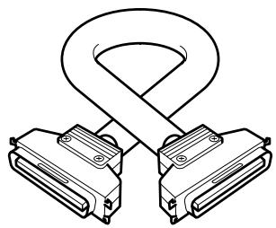
natural_image
Diagram of two connected electronic connectors with a coiled cable (no text or symbols)Power cord (for Canada and the U.S.) ... 1
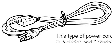
natural_image
Illustration of a multi-woven electrical plug with connectors, no text or symbols presentThis type of power cord is for use in America and Canada only. Do not use this power cord in places other than America or Canada.
Power cord (for Japan) ... 1
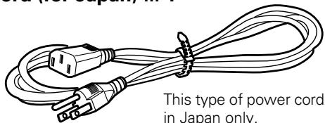
natural_image
Line drawing of a power cord with multiple leads and connectors, labeled 'This type of power cord in Japan only.'This type of power cord is for use in Japan only. Do not use this power cord in a places other than Japan.
Base stabilizer
DRM-7000: 4
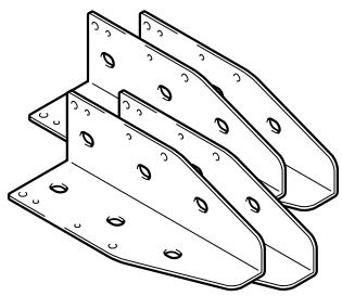
natural_image
Technical line drawing of three metal bracket components with mounting holes (no text or symbols)DRM-3000: 2
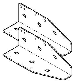
natural_image
Technical line drawing of two metal bracket components with mounting holes (no text or symbols)Lock release key ... 2
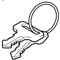
natural_image
Line drawing of a key with a ring (no text or symbols)Screw for use in attaching base stabilizers
DRM-7000 ... 12
DRM-3000 ... 6
Operating instructions ... 1
DISCS
Discs which may be used with the Pioneer DRM-7000/DRM-3000
The types of discs which may be used with the Pioneer DRM-7000/DRM-3000 vary depending on the types of drives being used, and for further information on the types of discs which may be used you should accordingly consult the operating instructions provided with your drive units.
Handling the discs
- Avoid touching the signal surface when you use a disc.
- To hold it, place your fingers on the edge of the disc or the edge of the center hole and the disc edge.

- Do not attach paper or stickers to the label side of the disc. Handle discs carefully and avoid damaging the label.
- Discs rotate at high speed in the changer. Do not use defective discs (e.g., cracked or considerably warped). Such discs may damage the changer.
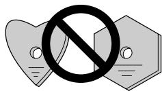
- DO NOT use non-standard discs, as these may adversely influence this unit and other equipment.
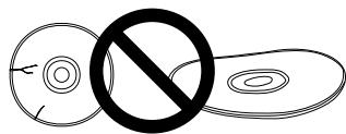
- DO NOT play a CD having other shape than a circular disc, such as heart shaped disc, or malfunction may occur.
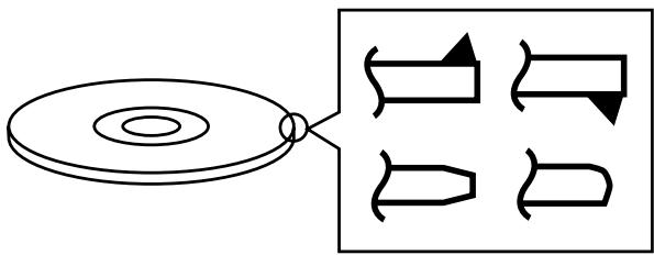
Do not use the following types of discs for they may cause malfunction of the unit or damage to the discs:
- Disc which has a molding flash (projected fin) left on the periphery as shown in the illustration.
- Disc with its edges are rounded or tapered as shown in the figure.
natural_image
Pure diagram of a circular component connected to four abstract geometric shapes, no text or symbols presentThe following is a list of operation items that may potentially lead to problems in component functioning.
| Issue | Potential Malfunction/Error | |
| 1. Installation | Do not place foreign objects inside the changer, since malfunction may result. | [E83], [E99], [E88] |
| Do not use the changer in locations subject to high concentrations of dust, heat, or humidity.* Do not install in locations directly exposed to outdoor dust or air.* Do not install near air conditioner vents or air cleaners. | Recording/playback malfunction | |
| Do not subject the recorder to impact or vibration during use.* Do not install in hallways or other areas near frequent pedestrian traffic. | Recording/playback malfunction | |
| 2. Connections | When connecting exterior SCSI cable, be sure that power is first turned off to host computer and changer.* When connecting internal SCSI cable, power may be left while connecting. | Changer malfunction |
| When installing a drive, be sure to connect the changer interface cable to the connector corresponding to the bay in which the drive is installed. If the cable is mistakenly connected to a neighboring connector, the discs may be damaged and the E99 error may occur. | [E83], [E99] | |
| Be sure to set the terminator switch to ON on the final component connected to the SCSI bus. If it is mistakenly set to OFF, the changer operation may be unstable. If malfunctions occur with the switch set to OFF, set the switch to ON and turn the power on again.* When a component's terminator switch is set to ON, if the component is subsequently removed from the SCSI bus, or if the component's SCSI cable is disconnected, the condition immediately reverts to the same state as when the terminator is OFF, thus resulting in the same condition as above. | Display window (LCD) doesn't appear correctly.Operation keys malfunction.Changer not recognized on the SCSI. | |
| When installing a drive, if the wiring monitor indicator does not flash, recheck and install the power cable connection, followed by the changer interface connection. | Changer does not detect drive. | |
| 3. Power ON/OFF | Never disconnect power while the changer is transporting a disc, or when the writer is recording data to a disc. | Changer malfunction.Data recording malfunction |
| When turning the power off and then on again, wait at least ten seconds after turning the power off before turning it on again. | ||
| 4. Control | During data recording, do not send commands from the disc writer to remove disc (Move Medium, Rezero Unit), since EC* error or write malfunction may occur (back buffer underrun). | Recording malfunction[EC*], (where * = 0 - F) |
| 5. Transporting Unit | When transporting the unit, pack the unit in its original packaging materials, and ship in an upright position. Do not transport the unit on its side. | |
| Do not transport the unit with drive units, 50-disc magazines or other optional accessories loaded (except for 20-disc hyper-magazine). When transporting the accessories, repack them in their original packaging materials. | ||
| Do not transport disc magazines with discs loaded. | ||
| 6. Error Correction | E8*, E9*, EF8, or EF3 errors cannot be corrected merely by resetting the changer's power on/off. The system administrator mode must be used to open and then close the door again. For these and other errors, see the Operating Instructions, p. 44. | [E8*], [E9*], [EF8], [EF3] (where * = 0 - F) |
| 7. Discs | Blank discs, discs which have experienced failed recording operations, and discs whose recording sessions have not been closed, cannot be used on the reader drive.* Use the writer drive to determine whether a disc is blank. | Reader drive malfunction[Set Up NG] error |
| Do not affix paper labels or seals to discs. Also, do not allow the printed surface of discs to become scratched.* If a paper label is removed incorrectly, it may leave behind pieces of adhesive that cause player malfunction; as a result, when removing an adhesive label, be sure to remove it carefully and fully, taking care not to leave an scratches on the surface of the disc. | Recording/playback malfunction[E83], [E99] | |
| Scratches, fingerprints, or dirt adhering to the surface of a disc may interfere with recording or playback. When handling discs, take care not to touch the signal surface (the reflective recording surface). Hold discs either by the outside edges, or by placing a finger in the center hole. | Recording/playback malfunction | |
| If a disc is soiled, wipe gently with a soft cloth in a radial direction, straight from the center outwards. Do not wipe in a circular pattern.* Use only the Pioneer Cleaning Cloth (Service Parts GED-009) for wiping discs. | Recording/playback malfunction | |
| To produce stable recording and playback, use only recommended discs. For recommended discs, consult your dealer or Pioneer's website. | Recording/playback malfunction | |
| This component does not support DVD-R for Authoring media. | Cannot record | |
| 8. Disc Magazines | When inserting discs in magazines, be sure they are inserted flat into the same slot; discs may be damaged if inserted diagonally (with left and right edges in differing slots). | [E83], [E99] |
| Do not allow the open end of magazines to point downward, since discs may fall out. | [E83] | |
| Insert magazines slowly into the changer, since discs may fly fall out if the magazine is inserted with excessive force.* When inserting a magazine, if the electronic buzzer sounds or error [E83 disc set NG] appears in the display, remove the magazine, press any dislodged discs back into the magazine, and slowly insert the magazine once again. | [E83] | |
| 9. Disc Reversal Unit | When the Pioneer Disc Flip Module DRM-UF701 is used in conjunction with the changer DRM-7000, the changer must be equipped with firmware Rev. 1.12 or later. Since malfunctions or disc damage may occur when used with firmware revisions earlier than 1.12, be sure to update your firmware before use to version 1.12 or later. For details regarding updating of firmware, consult your Pioneer service center, or retail dealer.* The DRM-3000 module is not limited by firmware revisions. | [EC*], (where * = 0 - F)Other malfunctions |
FRONT
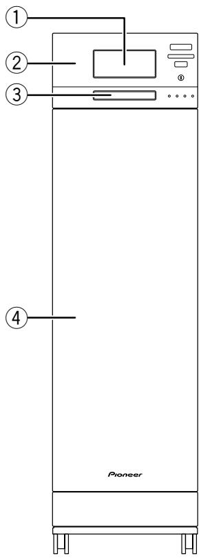
text_image
① ② ③ ... ④ Pioneer
text_image
ESC ← ↓ ↑ → ENT FUNCTION LOCK *UNLOCK POWER ROBOTICS DRIVE MAIL.SLOT BUSY BUSY OCCUPIEDFRONT ACCESS DOOR INSIDE

natural_image
Line drawing of a refrigerator interior with doors open, showing storage compartments and numbered components (no text or symbols)① 20-disc hyper magazine
② Control panel
③ Mailslot
④ Front access door
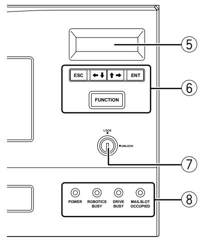
⑤ LCD message window
The backlight to the LCD message window is designed to automatically go into energy saving mode whenever more than 1 minute passes without any operations being performed from the control panel.
⑥ Operation keys
These keys are used to change the display items on the LCD message window and to select setting fields or values. Note that a lock release key is required in order to become effective these keys.
Escape key (ESC):
The escape key is used to step back from the message layer currently being displayed (i.e., to return to the previous display) or to halt operations.

This key is used to decrement displayed values or to move the display cursor down or to the left.

This key is used to increment displayed values or to move the display cursor up or to the right.
Enter key (ENT):
The enter key is used to step forward from the message layer currently being displayed or to initiate a specified operation.
Function key (FUNCTION):
The function key must be pressed in order to enter the system administrator mode.
⑦ Lock/Unlock key switch
Inserting a lock release key into this switch and rotating it 90 degrees releases the operation lock and makes it possible to perform operations from the control panel.
⑧ Status indicators
POWER:
This indicator lights up whenever the power is on.
ROBOTICS BUSY:
This indicator lights up whenever a disc transport mechanism is in operation.
DRIVE BUSY:
This indicator lights up whenever one or more discs are being placed on each drives.
MAILSLOT OCCUPIED:
This indicator lights up whenever a disc is placed in the closed mailslot.
⑨ Front bays
DRM-7000
For use with disc magazines: M1 – M7
DRM-3000
For use with disc magazines: M1 – M3
REAR
text_image
Technical diagram of a server rack with labeled components, showing internal structure and mounting points.REAR ACCESS DOOR INSIDE

natural_image
Technical line drawing of a vertical panel or enclosure with internal compartments and a labeled component (no text or symbols present)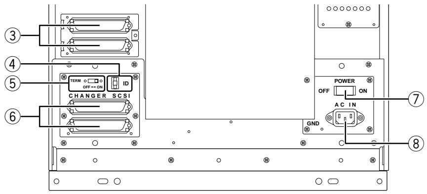
text_image
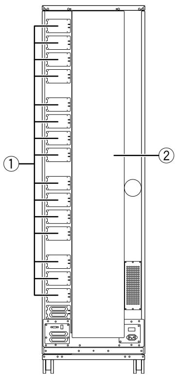
③ ④ ⑤ ⑥ CHANGER SCSI TERM OFF → ON ID POWER ON OFF AC IN GND ⑦ ⑧① Rear plates
These plates cover the space for attaching the connector panels.
② Rear access door
③ Drive SCSI ports (attached connector panel)
④ SCSI ID switch (ID)
This switch is used to assign the changer SCSI ID. If you would like to decrement the displayed SCSI ID, push the small switch just above the numeric display by a nib. And if you would like to increment, push the small switch just below the numeric display. Note that SCSI ID is set to '6' at the time of shipment.
⑤ SCSI termination switch (TERM)
This switch is for SCSI termination. Note that this switch is set ON at the time of shipment and it must be kept ON during the changer installation. But when the SCSI bus connection is completed and the changer is not the last device on the SCSI bus, it must be set OFF certainly.
⑥ Changer SCSI ports (CHANGER SCSI)
⑦ Power switch (POWER)
This switch is used to turn the power to the changer on and off.
⑧ Power inlet (AC IN)
The power cord is inserted into this power inlet. (Note that you should always be sure to use only the power cord provided with your changer.)
⑨ Rear bays
DRM-7000
For use with disc magazines: M8 – M15
For use with optional units/modules: Bays #1 – 16 DRM-3000
For use with disc magazines: M4 – M7
For use with optional units/modules: Bays #1 - 8
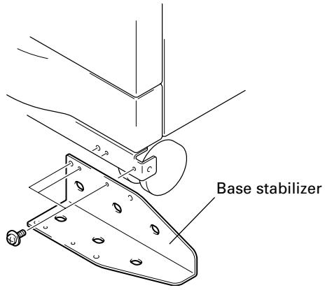
STEP 1
1. Attach the base stabilizers.
To prevent the unit from falling over, be sure to attach the accessory base stabilizers. The DRM-7000 is provided with four stabilizers (one at each corner), and the DRM3000 is provided with two (rear corners only).
text_image
Base stabilizerNOTES:
- Be sure to attach the base stabilizers before doing anything else.
- Note that the base stabilizers also serve to protect the ports and cables on the rear of the unit.
- Note that any damage incurred as a result of the unit falling over or any damage caused to the rear ports or cables as a result of a failure to install the base stabilizers will not be covered under warranty.
- In the case of the DRM-3000, be sure to attach the stabilizers only to the rear corners of the unit.
2. Deciding on the location where the changer is to be installed
The changer is designed with a rear access door which can be opened in inserting or removing drives or disc magazines, and the location where the changer is to be installed should be chosen so as to allow a minimum of 50cm of space between the rear of the changer and the nearest wall so as to leave enough room to open the rear access door and insert or remove drives or disc magazines.
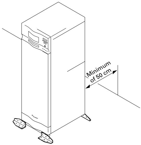
text_image
Minimum of 50 cm3. Lock the casters
Four casters at the bottom of DRM-7000/DRM-3000 allow it to be moved lightly but they must be locked soon if you place the changer on the chosen location. A caster is locked by lowering its lever.
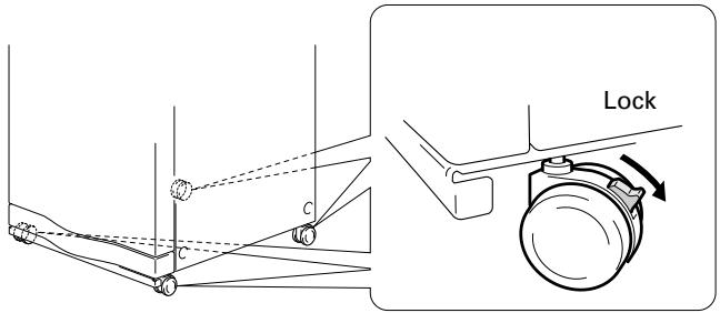
text_image
Lock4. Connect power cord
Insert the power cord into the power inlet on the rear of the changer and then insert the plug into a wall power outlet.
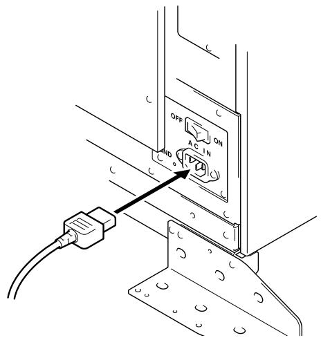
text_image
OFF AC IN NDNOTE:
Always be sure to use only the power cord supplied with your changer.
Also be sure to follow the instructions on the label on the package and use only that cord designed for use in the location in which the power cord is to be used.
STEP 2
Readying the changer for operation
In order to ready the changer for operation, perform the following steps in the order indicated.
- Turning on the power (see p. 17)
- Loosening the shipping screws (see p. 17)
- Installing drive units (see p. 17)
- Connecting SCSI cables (see p. 18)
- Inserting disc magazines (see p. 20)
- Closing access doors (see p. 23)
1. Turning on the power
When the power is first turned on, both the front and rear access doors will automatically open. This is not a faulty operation but the function of the shipping screws tightened at the time of shipping or re-transporting.
NOTES:
- Be sure not to close neither the front nor rear access door until all drives and disc magazines have been installed.
- If the door does not open when the power is turned on, wait until the initialization routine has completed and the LCD shows the user mode display (p. 23), then refer to p. 37 ("System Administrator Mode: Door Sub-mode") for instructions on opening the door.
2. Loosening the shipping screws
When the front access door is opened, shipping screws may be seen at near the bottom inside the changer. These screws are attached to prevent damage to the built-in mechanism of the changer during transporting.
Shipping screws are designed so that they can only be loosened and cannot be removed so as to prevent their
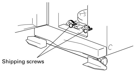
text_image
Shipping screwsbecoming lost.
NOTES:
- Be sure to tighten again the shipping screws before re-transporting the changer.
- If you or someone close the front or the rear access door with the shipping screws loosened, the closed door can not open automatically like before. And when the both doors are closed, the changer starts its mechanical initialization. So if you have not finished the installation yet, it is necessary to open the access doors again to continue with installation. (See System administrator mode: Door submodes on p. 37 for further information.)
3. Installing drive units
No tools are required for attaching drive units. Note that while drives may be installed in any of the rear bays from #1 – #8, the location of the connector panel that has been attached at the time of shipment had been designed for drives to be installed in bays #1 and #2.
1. Attaching add-on connector panels, if necessary
Screwdriver

natural_image
Technical line drawing of two mechanical assembly components with mounting brackets and bolts (no text or symbols)2. Attaching drive units
Before installation, be sure to specify the following settings at the rear of each drive to be installed. (See the operating instructions provided with drive for details.)
- SCSI ID assignment
Specify the SCSI IDs to be used so as to ensure that the same SCSI ID is not assigned by more than one drive on the same SCSI bus. - Termination
Set the termination switch of the last drive in the SCSI chain to the ON position.
① When inserting a drive, be sure to place the drive on the changer guide rails and push the drive in until the lock lever on the drive shifts to the locked position. Maybe you can hear a clicking sound then.
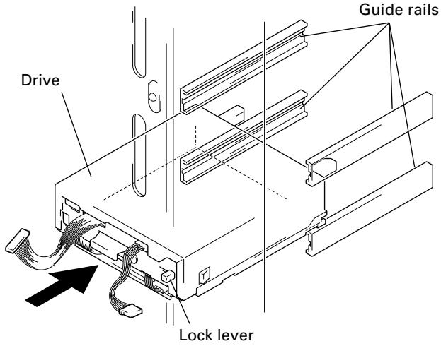
text_image
Drive Guide rails Lock lever② Connect the power cable.
- When the power cable has been connected, the wiring monitor indicator on the rear of the drive (orange) will light up.
- When the termination switch of the drive is set to on, the termination indicator (green) will light up.
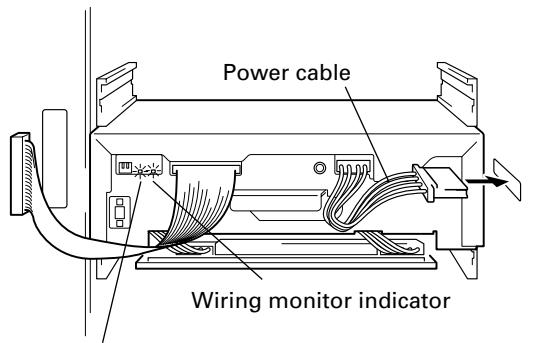
text_image
Power cable Wiring monitor indicatorTermination indicator
③ Connect the changer interface cable.
- When the changer interface cable has been connected, the wiring monitor indicators will flash at two-second intervals.
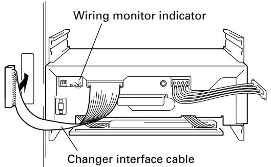
text_image
Wiring monitor indicator Changer interface cableNOTE:
Connect the changer interface cable to the connector corresponding to the bay in which the drives have been installed. (Note that labels are affixed to connectors indicating the corresponding bay number.) Note that it is extremely important to do this, as connecting the changer interface cable to a neighboring bay will result in damage to discs and the disc transport mechanism.
3. Reading and self-checking the installed drive's SCSI ID by the changer
- If all drives have been assigned different SCSI IDs, a buzzer will sound once.
- If the same SCSI ID has been assigned to two or more drives, a buzzer will sound three times.
NOTES:
- If installed drives are to be connected to different SCSI buses, then the same SCSI ID assigned to each of the drives may be all right.
- Even if none of the drives installed within a changer has been assigned the same SCSI ID, it is necessary to check that the same SCSI ID is not assigned to other devices (e.g., hard disks) on the same SCSI bus.
4. Connecting SCSI cables
After installing all drives and checking to make sure that they have been properly connected, install the SCSI interface cables.
NOTES:
- Maximum usable SCSI cables length is 6 meters (including length of wiring inside changer). If the SCSI cable has extra unused connectors, connect the final (end) connector to the terminating drive; the extra intermediate connectors may be left unconnected if not required. (See page 19, "SCSI Cable Connection Example").
- When installing 7 or more drives or when creating multi SCSI buses system for 6 drives or less, additional multi drive connector panels or single drive connector panels will be required.
- When connecting the changer to a host computer, always be sure to first turn off the power to both the changer and the host computer. After the connections are finished, turn on the power to the changer before turning the power to the host computer back on.
- The changer SCSI termination switch is set to ON at the time of shipment. Always make sure that the changer SCSI termination switch is set to OFF when the changer is not the last device in the SCSI chain.
- Note that the DRM-7000/DRM-3000 is unable to recognize the existence of faulty SCSI cable connections or mistakes in the assignment of SCSI IDs, and for this reason you should always be sure to restart the host computer after installation to make sure that all drive units and the changer are properly recognized. This is the only way of confirming that all SCSI devices are installed properly.
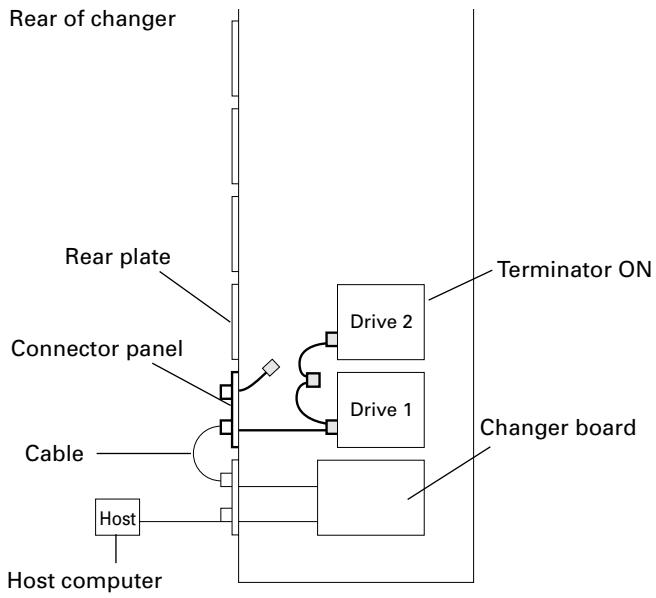
SCSI Cable Connection Example:
- Install 2 internal drives within the changer in a daisy-chain configuration and connect the drives to the changer.
Total length of SCSI cables: approx. 2.1m
(Note that this does not include the length of the cable running from the host computer to the changer.)
flowchart
graph TD
    A["Host computer"] --> B["Cable"]
    B --> C["Connector panel"]
    C --> D["Rear plate"]
    D --> E["Rear of changer"]
    C --> F["Changer board"]
    F --> G["Drive 1"]
    F --> H["Drive 2"]
    F --> I["Terminator ON"]
    style A fill:#f9f,stroke:#333
    style B fill:#ccf,stroke:#333
    style C fill:#cfc,stroke:#333
    style D fill:#fcc,stroke:#333
    style E fill:#cff,stroke:#333
    style F fill:#ffc,stroke:#333
    style G fill:#fcf,stroke:#333
    style H fill:#cff,stroke:#333
    style I fill:#ffc,stroke:#333
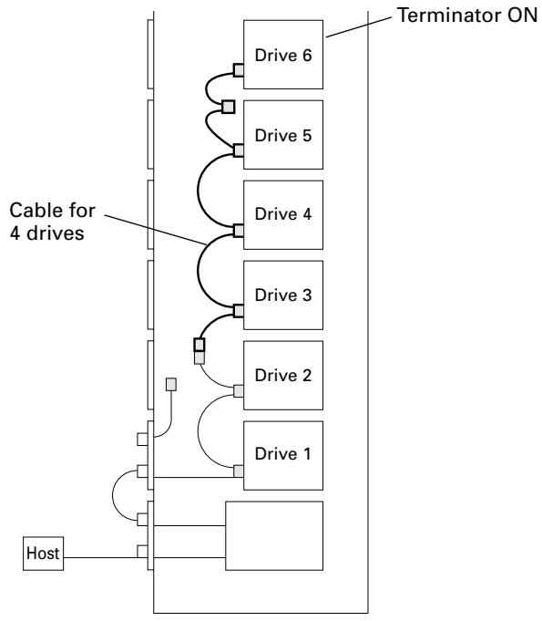
- Install 6 internal drives within the changer in a daisy-chain configuration and connect the drives to the changer. (Additional cable for 4 drives will be needed.)
Total length of SCSI cables: approx. 2.9m
(Note that this does not include the length of the cable running from the host computer to the changer.)
flowchart
graph TD
    A["Host"] --> B["Drive 1"]
    B --> C["Drive 2"]
    C --> D["Drive 3"]
    D --> E["Drive 4"]
    E --> F["Drive 5"]
    F --> G["Drive 6"]
    G --> H["Terminator ON"]
    style A fill:#f9f,stroke:#333
    style H fill:#ccf,stroke:#333
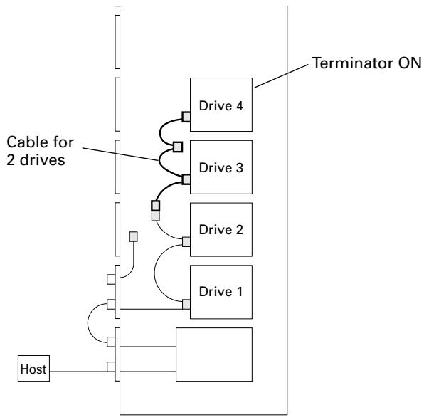
- Install 4 internal drives within the changer in a daisy-chain configuration and connect the drives to the changer. (Additional cable for 2 drives will be needed.)
Total length of SCSI cables: approx. 2.5m
(Note that this does not include the length of the cable running from the host computer to the changer.)
flowchart
graph TD
    A["Host"] --> B["Drive 1"]
    B --> C["Drive 2"]
    C --> D["Drive 3"]
    D --> E["Drive 4"]
    E --> F["Terminator ON"]
    style A fill:#f9f,stroke:#333
    style F fill:#ccf,stroke:#333
    note right of A Cable for 2 drives
    note right of F Terminator ON
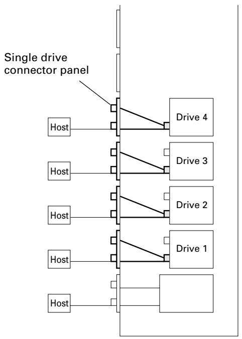
- Connect 4 drives directly to the individual host adapters. (Additional four single drive connector panels will be needed and pre-attached multi drive connector panel may be removed.)
flowchart
graph TD
    A["Single drive connector panel"] --> B["Host"]
    A --> C["Drive 4"]
    A --> D["Drive 3"]
    A --> E["Drive 2"]
    A --> F["Drive 1"]
    A --> G["Host"]
    A --> H["Host"]
5. Inserting disc magazines
Any of the following methods may be used to insert discs into the changer:
- Insert discs into a normal-type 50-disc magazine and then insert the magazine into the changer.
- Insert discs into a 20-disc hyper magazine and then insert the magazine into the changer.
- Use the control panel to specify the slot into which a disc is to be inserted and transport a disc to the specified slot from the mailslot.
- Issue some commands from the host computer to open the mailslot and transport a disc to the specified slot from the mailslot.
- Issue some commands from the host computer to move discs in the loaded hyper magazine to some slots within the loaded 50-disc magazines.
● Hyper magazine is not able to be inserted or removed when the power to the changer is turned off.
- Methods 3 through 5 may be used after the changer is ready for operation. When inserting discs in these methods, always be sure to insert empty disc magazines first.
Also note that methods 3 through 5 are used when inserting locked-type 50-disc magazines. (See System administrator mode: Mailslot submode on p. 34 for further information.)
- Whether or not it is possible to use methods 4 and 5 depends on the function of changer control software being used, and you should check the manual which comes with the software to check if it supports these methods to insert discs.
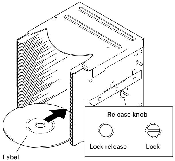
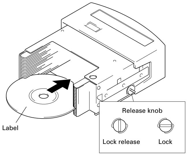
1. Insert discs into a normal-type 50-disc magazine and insert the magazine into the changer.
① Turn the release knob to the vertical direction to unlock.
② Insert discs.
③ Turn the release knob to the horizontal direction to lock the discs into place.
text_image
Label Release knob Lock release LockNOTES:
- Insert with label facing upward.
- Insert discs horizontally. Otherwise it may result in damage to the discs.
- Be careful not to scratch the reflective signal recording surface.
- Do not turn a disc magazine upside down while the lock is disengaged. Otherwise it may result in discs falling out of the magazine.
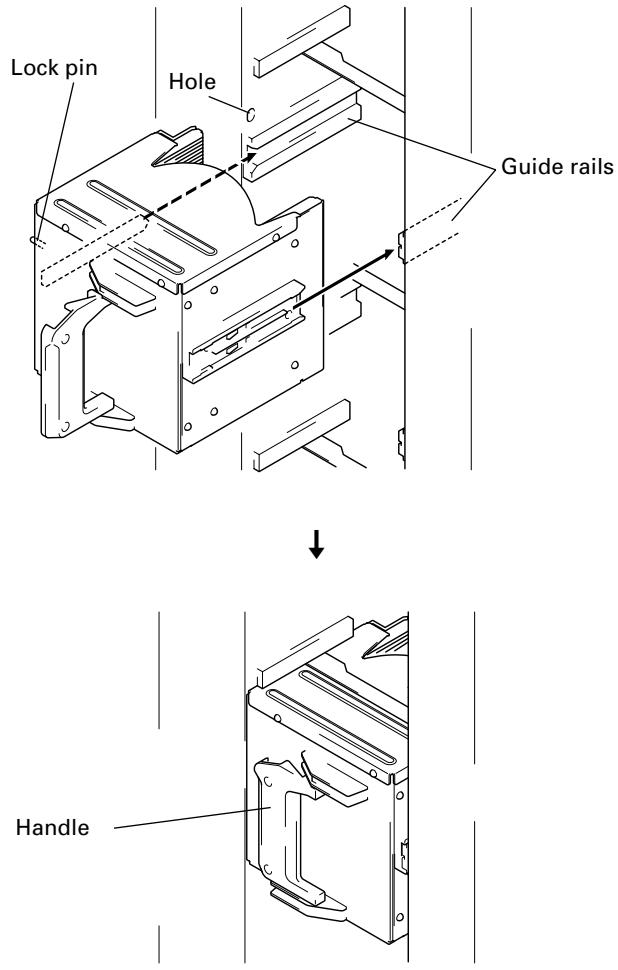
④ Insert magazine into changer.
Holding the handle of the disc magazine, insert the disc magazine into the changer following the changer guide rails until it runs against the stopper.
And turn the handle to the left with pushing the magazine in so that the lock pin on the left of the magazine slides into the corresponding hole along the side of the changer.
Example: Loading magazine in front bay
text_image
Lock pin Hole Guide rails HandleShown above is the insertion to the front magazine bay. Though the insertion to the rear magazine bay is almost same but note that the proper installation position is in the place where it is very secluded.
To remove a disc magazine from the changer, pull the handle towards you and pull the magazine from the changer.
Whenever a disc magazine is inserted into the changer, its ID will be automatically read in and displayed on the LCD message window within a few seconds.
$$ \begin{array}{c} \texttt {M 1 L o c k e d - t y p e} \ \texttt {I D = * * * * * * * * * * *} \end{array} $$
A similar message will also be displayed whenever a disc magazine has been removed.
$$ \begin{array}{c} \text {M1} \ \text {Locked - type} \ \text {out} \end{array} $$
If both of these messages appear together in rapid succession, it indicates that a disc magazine has not been correctly inserted, and you should check the magazine to make sure that it has been inserted properly again.
2. Insert discs into a 20-disc hyper magazine and insert the magazine into the changer.
① Turn the release knob to the vertical direction to unlock.
② Insert discs.
③ Turn the release knob to the horizontal direction to lock the discs into place.
text_image
Label Release knob Lock release LockNOTES:
- Insert with label facing upward.
- Insert discs horizontally. Otherwise it may result in damage to the discs.
- Be careful not to scratch the reflective signal recording surface.
- Do not turn a disc magazine upside down while the lock is disengaged. Otherwise it may result in discs falling out of the magazine.
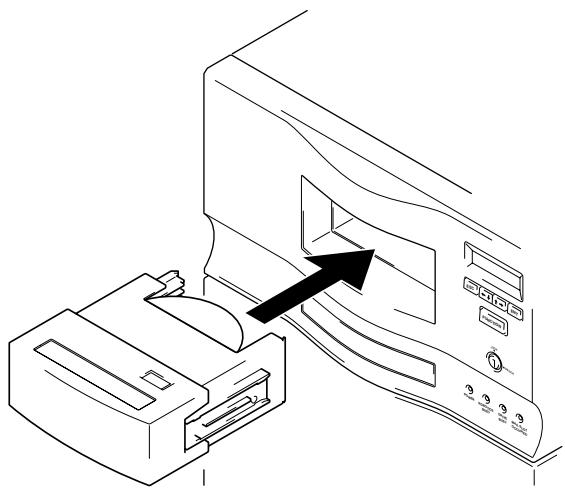
④ Insert magazine into changer.
Once the hyper magazine has been inserted partly into the changer, it will be automatically loaded in.
natural_image
Line drawing of a printer with an arrow pointing to the front panel (no text or symbols present)When the hyper magazine has been loaded, a unique magazine ID will be displayed together with the record of the locking mechanism.
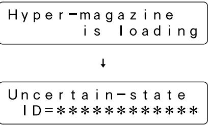
text_image
Hyper-magazine is loading ↓ Uncertain-state ID=**********Note that the magazine will be automatically ejected if the changer is unable to read the magazine ID, and that if this happens you should try inserting the magazine again.
NOTE:
If hyper magazine has been installed, see the instructions given in System administrator mode: Hyper submode (p. 35) removing the hyper magazine.
Serial numbers are assigned to each of the slots within the changer into which discs may be inserted. Note that these numbers are assigned even when no disc magazine has been inserted, and that for this reason slot numbers never change even when a new disc magazine is inserted.
DRM-7000
| Disc storage location | Slot number(Disc No.) | Disc storage location | Slot number(Disc No.) | ||||
| Hyper magazine Hyper | Slot 20 to Slot 1 | #770 to #751 | hyp-20 to hyp-01 | Magazine bay 15 M15 | Slot 50 to Slot 1 | #750 to #701 | M15-50 to M15-01 |
| Magazine bay 7 M7 | Slot 50 to Slot 1 | #350 to #301 | M7-50 to M7-01 | Magazine bay 14 M14 | Slot 50 to Slot 1 | #700 to #651 | M14-50 to M14-01 |
| Magazine bay 6 M6 | Slot 50 to Slot 1 | #300 to #251 | M6-50 to M6-01 | Magazine bay 13 M13 | Slot 50 to Slot 1 | #650 to #601 | M13-50 to M13-01 |
| Magazine bay 5 M5 | Slot 50 to Slot 1 | #250 to #201 | M5-50 to M5-01 | Magazine bay 12 M12 | Slot 50 to Slot 1 | #600 to #551 | M12-50 to M12-01 |
| Magazine bay 4 M4 | Slot 50 to Slot 1 | #200 to #151 | M4-50 to M4-01 | Magazine bay 11 M11 | Slot 50 to Slot 1 | #550 to #501 | M11-50 to M11-01 |
| Magazine bay 3 M3 | Slot 50 to Slot 1 | #150 to #101 | M3-50 to M3-01 | Magazine bay 10 M10 | Slot 50 to Slot 1 | #500 to #451 | M10-50 to M10-01 |
| Magazine bay 2 M2 | Slot 50 to Slot 1 | #100 to #051 | M2-50 to M2-01 | Magazine bay 9 M9 | Slot 50 to Slot 1 | #450 to #401 | M9-50 to M9-01 |
| Magazine bay 1 M1 | Slot 50 to Slot 1 | #050 to #001 | M1-50 to M1-01 | Magazine bay 8 M8 | Slot 50 to Slot 1 | #400 to #351 | M8-50 to M8-01 |
NOTE:
Although slot numbers reach as high as '770', this does not mean that as many as 770 discs may be available within the DRM-7000.
DRM-3000
| Disc storage location | Slot number(Disc No.) | Disc storage location | Slot number(Disc No.) | ||||
| Hyper magazine Hyper | Slot 20 to Slot 1 | #370 to #351 | hyp-20 to hyp-01 | Magazine bay 7 M7 | Slot 50 to Slot 1 | #350 to #301 | M7-50 to M7-01 |
| Magazine bay 3 M3 | Slot 50 to Slot 1 | #150 to #101 | M3-50 to M3-01 | Magazine bay 6 M6 | Slot 50 to Slot 1 | #300 to #251 | M6-50 to M6-01 |
| Magazine bay 2 M2 | Slot 50 to Slot 1 | #100 to #051 | M2-50 to M2-01 | Magazine bay 5 M5 | Slot 50 to Slot 1 | #250 to #201 | M5-50 to M5-01 |
| Magazine bay 1 M1 | Slot 50 to Slot 1 | #050 to #001 | M1-50 to M1-01 | Magazine bay 4 M4 | Slot 50 to Slot 1 | #200 to #151 | M4-50 to M4-01 |
NOTE:
Although slot numbers reach as high as '370', this does not mean that as many as 370 discs may be available within the DRM-3000.
6. Closing access doors
First check to make sure that all components have been installed into place and all cables have been connected.
If this has been done, close the front and the rear access doors, then the initialization of the changer mechanism will begin.
When initialization has been completed, a message like that shown below will be displayed on the LCD message window.
| Robotics | ready |
| Drive1 | no disc |
The first line of this message is used to indicate the status of the disc changer mechanism, and the second line is used to indicate the installed drive number and to indicate whether or not a disc has been loaded into the drive in question.
Drive numbers are assigned in sequence from the lowermost to the uppermost drive.
NOTE:
If the maximum number of drives appears on the LCD message window is shorter than the number of drives installed, open the rear access door and check the power cables and the changer interface cables to all drives installed. (See System administrator mode: Door submodes on p. 37 for information on how to open the rear access door.)
The Pioneer DRM-7000/DRM-3000 has two operation modes. One is user mode performing the computer-based operations and the other is system administrator mode mainly performing manual operations from the control panel. By dividing the admitted operations into these two modes, it becomes possible to prevent interference, conflicts, or clashes occurring between operations performed from the control panel and commands issued by the host computer.
USER MODE
Once a changer has been finished its power on initialization or closing doors after installation, it will enter user mode and it will become able to be controlled by the changer control software and database management software running on the host computer. When a changer is running normally in user mode, the LCD message window will display a series of the following status messages in one-second intervals.
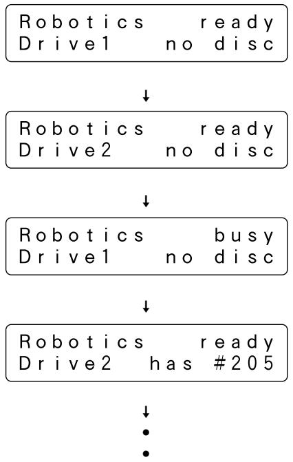
flowchart
graph TD
    A["Robotics ready\nDrive1 no disc"] --> B["Robotics ready\nDrive2 no disc"]
    B --> C["Robotics busy\nDrive1 no disc"]
    C --> D["Robotics ready\nDrive2 has #205"]
    D --> E["•"]
    D --> F["•"]
When operating in user mode, the changer will operate in accordance with commands issued by the host computer.
SYSTEM ADMINISTRATOR MODE
The privilege to perform operations from the control panel is given to the system administrator who keeps lock release keys. Note that the following steps must be performed in order to switch to system administrator mode.
- Insert lock release key into the key switch located on the control panel and rotate 90 degrees to shift the switch to UNLOCK position.
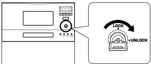
text_image
LOCK •UNLOCK- Press the FUNCTION key.
When the changer enters system administrator mode, a message like that shown below will be displayed on the LCD message window:
System administrator mode is further divided into 8 different submodes.
Information submodes
These submodes enable the system administrator to read a changer's current settings or read data stored within a changer. Note that these submodes do not affect the operations performed by the host computer and the system administrator can obtain a variety of information without interfering with the control of the changer from the host computer.
● Inquiry submode (see p. 26)
- Config submode (see p. 26)
- Option submode (see p. 28)
● Info submode (see p. 32)
Maintenance submodes
These submodes are used to maintain discs and their status within the changer. Sometimes these submodes may use the disc transport mechanism. Therefore whenever the changer enter any one of these submodes, some commands issued by the host computer may be ignored.
● Mailslot submode (see p. 34)
● Hyper submode (see p. 35)
● Probe submode (see p. 36)
● Door submode (see p. 37)
NOTE:
The DRM-7000/DRM-3000 is designed so as to prohibit the use of maintenance submodes from the host computer. Note that while it is possible to enter system administrator mode even though the use of these submodes is prohibited, only the information submodes will be able to be used.
System administrator mode settings screen are displayed in the sequence indicated below.
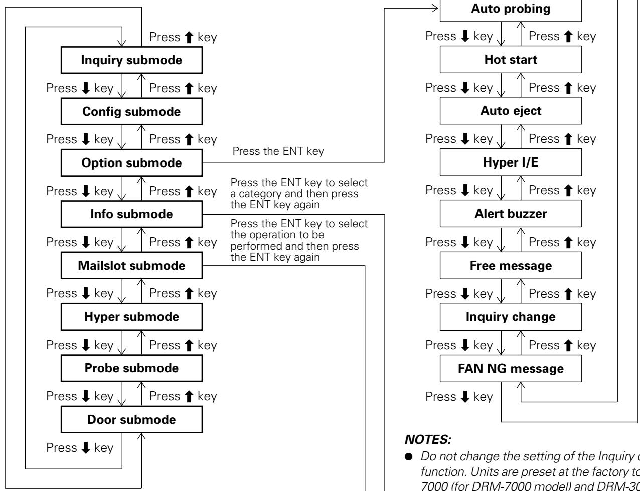
flowchart
graph TD
    A["Inquiry submode"] -->|Press ↓ key| B["Config submode"]
    B -->|Press ↓ key| C["Option submode"]
    C -->|Press ↓ key| D["Info submode"]
    D -->|Press ↓ key| E["Mailslot submode"]
    E -->|Press ↓ key| F["Hyper submode"]
    F -->|Press ↓ key| G["Probe submode"]
    G -->|Press ↓ key| H["Door submode"]
    H -->|Press ↓ key| A
    A -->|Press ↑ key| I["Auto probing"]
    I -->|Press ↓ key| J["Hot start"]
    J -->|Press ↓ key| K["Auto eject"]
    K -->|Press ↓ key| L["Hyper I/E"]
    L -->|Press ↓ key| M["Alert buzzer"]
    M -->|Press ↓ key| N["Free message"]
    N -->|Press ↓ key| O["Inquiry change"]
    O -->|Press ↓ key| P["FAN NG message"]
    P -->|Press ↓ key| Q["Output"]

    style A fill:#f9f,stroke:#333
    style B fill:#f9f,stroke:#333
    style C fill:#f9f,stroke:#333
    style D fill:#f9f,stroke:#333
    style E fill:#f9f,stroke:#333
    style F fill:#f9f,stroke:#333
    style G fill:#f9f,stroke:#333
    style H fill:#f9f,stroke:#333
    style I fill:#f9f,stroke:#333
    style J fill:#f9f,stroke:#333
    style K fill:#f9f,stroke:#333
    style L fill:#f9f,stroke:#333
    style M fill:#f9f,stroke:#333
    style N fill:#f9f,stroke:#333
    style O fill:#f9f,stroke:#333
    style P fill:#f9f,stroke:#333
    style Q fill:#f9f,stroke:#333
Pressing the ESC key when in inquiry submode will cause the system to return from system administrator mode to user mode.
NOTES:
- Do not change the setting of the Inquiry change function. Units are preset at the factory to DRM-7000 (for DRM-7000 model) and DRM-3000 (for the DRM-3000 model).
- Do not change the setting of the FAN NG message function. Units are set to factory default of ON.
Log
Contents
Run-statistics
Swap
Remove
Add
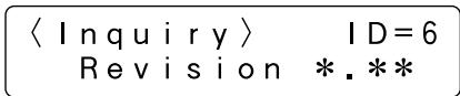
Inquiry submode
Inquiry submode is the entry to system administrator mode and also the exit to user mode. Here the DRM-7000/DRM-3000 displays information its own. The data displayed is the same as that obtained when the host computer issues an SCSI INQUIRY command to the changer. Your changer's current SCSI ID and the firmware revision is seen here.
$$ \langle \text { Inquiry } \rangle \quad I D = 6 $$
$$ \text { Revision } * \ast \ast $$
Pressing the ENT key at this time then the changer's model name and device ID (i.e., serial number) to be displayed.
$$ D R M - 7 0 0 0 $$
$$ \text { serial } = * * * * * * * $$
Pressing the ESC key causes the display to return one level above from the message currently being displayed.
To change the changer's SCSI ID, use the SCSI ID switch located at the lower left at the rear of the changer.
When the setting value of the SCSI ID switch is altered, the display will show a message like that shown below. (Note that the message shown here is the message which would be displayed when the SCSI ID is changed from '6' to '5'.)
$$ \langle \text { Inquiry } \rangle \mathrm{ID} = 6 (5) $$
$$ \text { Revision } * \ast \ast $$
The SCSI ID will be updated only when the power to the changer is turned OFF and ON or the host computer resets the SCSI bus on which the changer is.
Config submode
Config submode is the mode to browse the current status of the magazine bays and the rear bays. It may be used to make sure that all components currently installed in the changer have been properly recognized by the changer.
$$ \langle \text { C o n f i g } \rangle $$
$$ \text { Setup browser } $$
Pressing the ENT key causes the display to switch to the 'select bay' screen. Press the ↓ or ↑ key to select either the magazine bay or the rear bay.
$$ \text { Magazine - bay or } $$
$$ \underline {{\text { Rear(drive) - bay? }}} $$
Operation when the rear bay has been selected
Pressing the ENT key first displays the component loaded in rear bay #1.
- The bay number to be displayed is selected by pressing the or key.
$$ \text { Bay } # 1 = \text { Drive } 1 $$
$$ \text { DVDROM DVD - D7563 } $$
$$ \text { Press } \uparrow \text { or } \downarrow \text { key } $$

$$ \text { B a y } # 5 \& # 6 $$
$$ \texttt {f l i p u n i t} $$
$$ \text { Press } \uparrow \text { or } \downarrow \text { key } $$

$$ \text { B a y } # 9 $$
$$ \begin{array}{c} \text {no component} \end{array} $$
$$ \text { Press } \uparrow \text { or } \downarrow \text { key } $$

$$ B a y # 1 5 \& # 1 6 = M 1 5 $$
$$ \text { ID } \quad \ast \ast \ast \ast \ast \ast \ast \ast \ast \ast \ast \ast $$
Example of display for DRM-7000
- If the component that has been inserted in the bay displayed is a drive unit, it is possible to read out the SCSI ID, termination switch settings, and device ID of the drive in question.
Press the ENT key when the displayed is the bay in which a drive has been inserted, then it displays the above information.
$$ \text { sc si ID = 1 TermOFF } $$
$$ \text { dev } - \mid D = * * * * * * * $$
- If a disc has been transported to the drive, it is also possible to press the ENT key to display the disc number.
Disc in Drive1
is #*** (M**-**)
To confirm the type of magazine installed, press the ESC key to return to the bay select screen, then select the desired magazine bay.
NOTE:
Some types of stored information are in layers. Then pressing the ENT key may cause the display to proceed to the next layer and pressing the ESC key causes the display to return one level above from the message currently being displayed. Note that pressing the ESC key too many times will cause the system to return to user mode.
Operation when the magazine bay has been selected
- Pressing the ENT key will cause the hyper magazine ID to be displayed.
Hyper magazine
ID=*****
If a hyper magazine is not inserted, the following message will be displayed instead.
Hyper magazine removed
- Pressing the ↑ key while a hyper magazine is being displayed will cause the magazine IDs to be displayed in sequence beginning from magazine bay 1 (M1).
M1 (front-bottom)
ID=************************
Press ↑ key
↓
M2
ID=*****
When no disc magazine has been inserted, the message displayed will be as indicated below.
M7 (front-top)
removed
Example of display for DRM-7000
As the rear bays are multipurpose bays, sometimes some bays cannot be used as magazine bays because drives have been installed instead. Then the message displayed will be like that indicated below.
M8 ( rear-bottom)
not available
Example of display for DRM-7000
- When you wish to check to see what type of disc magazine has been installed, press the ENT key.
Normal-type
- Pressing the ↑ key while magazine bay 15 (M15) is being displayed will cause the display to return to a hyper magazine display.
When you wish to view drives, press the ESC key to return to the 'select bay' screen and then select the rear bay.
NOTE:
Some types of stored information are in layers. Then pressing the ENT key may cause the display to proceed to the next layer and pressing the ESC key causes the display to return one level above from the message currently being displayed. Note that pressing the ESC key too many times will cause the system to return to user mode.
Option submode
Some changer functions may be selected at user request. In order to allow system administrators to make the most of the features provided by changer control software and database management software, optional functions may be selected as needed. Note that requirements concerning security levels or operations performed at the time of errors may also change depending on the location in which the changer has been installed, and that options should be selected accordingly.
<Option>
User's choice
Option submode may be used to specify the following optional functions.
- Auto probing (Set OFF at the time of shipment)
- Hot start (Set OFF at the time of shipment)
- Auto eject (Set ON at the time of shipment)
- Hyper I/E (Set ON at the time of shipment)
- Alert buzzer (Set ON at the time of shipment)
- Free message (Set OFF at the time of shipment)
1. Auto probing
It is possible that discs have been inserted into normal-type 50-disc magazines and hyper magazines before these magazines are inserted into the changer. But it does not mean that these imported discs are ready to use because the changer and the host computer have not recognized yet which slot holds a disc or not. Therefore the first thing to do is examining which slot a disc is in, that is called probing.
While this probing function is usually performed by the changer control software running on the host computer, in cases where users wish to perform this before connecting the changer to the host computer or in cases where the changer control software being used does not support such probing function, probe submode (see p. 36) may be used instead. Using probe submode, however, may be inconvenient since it requires that all of the disc magazines to be checked be specified one by one.
Auto probing may be used to have the changer automatically check all disc magazines which need to be checked to determine whether or not discs have been inserted.
Auto probing?
Press the ENT key ↓
Auto probing is set to ON/OFF
Press the ← key to set to ON ↓
Auto probing is set to ON/OFF
Press the ENT key ↓
Auto probing is activated
(Note that an "Auto probing is prohibited" message will be displayed if auto probing is set to OFF.)
Note that even after switching auto probing function from OFF to ON, auto probing will not actually be performed until a reset is performed, a hyper magazine is inserted or the mechanism initialization is finished after access doors are closed.
When auto probing begins, the changer will begin to check whether all slots of the disc magazines to be checked in sequence to determine whether they are "empty" or "full".
To turn auto probing temporarily off, turn the key switch to UNLOCK position and press the ESC key.
NOTES:
- It takes approximately 2 minutes to check a 50-disc magazine.
- Some commands from the host computer cannot be executed while auto probing is being performed.
2. Hot start
When discs have been transported to drives and the power to the changer is turned off and then the power to the changer is turned back on, then the discs will be automatically returned to their original slots. (Note that this automatic disc return operation is not performed after a SCSI bus reset.)
For discs which are accessed frequently, however, it is possible to use the hot start feature to make those discs accessible immediately after power is turned on by leaving the discs in the drives which had used them.
Hot start function is an optional function and it enables to leave discs on the drives that had been using when the power is turning on.
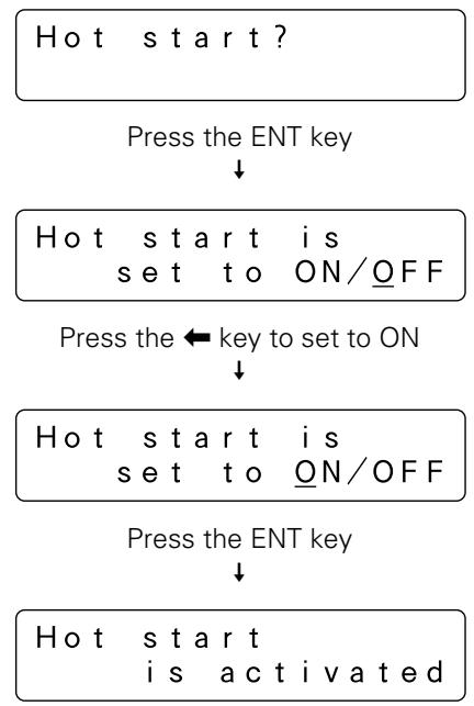
flowchart
graph TD
    A["Hot start?"] --> B["Press the ENT key"]
    B --> C["Hot start is set to ON/OFF"]
    C --> D["Press the leftarrow key to set to ON"]
    D --> E["Hot start is set to ON/OFF"]
    E --> F["Press the ENT key"]
    F --> G["Hot start is activated"]
(Note that a "Hot start is prohibited" message will be displayed if hot start function is set to OFF.)
NOTE:
Hot start function cannot be used when the changer control software is designed so as to force discs to be returned to their original slots.
3. Auto eject
In network environments there are often times when changers are installed near servers far from the locations in which user terminals are located.
In environments such as these, when a user uses the changer control software to issue a command requesting a disc within a changer be removed through a mailslot, it is necessary for the user to go to the location where the changer in question has been installed in order to remove the disc, but before the user reaches the changer the mailslot in which the disc has been transported may already have been opened.
This may be convenient for some cases, however, unless a system administrator resides near the changer it is as if there were no security at all, and the same holds true of the ejection of a hyper magazine.
This is the reason why it has been made possible to turn OFF auto eject function. Placing restrictions on the automatic ejection of mailslot tray and on the automatic ejection of a hyper magazine, makes it possible to maintain a certain level of security.
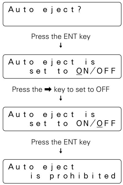
flowchart
graph TD
    A["Auto eject?"] --> B["Press the ENT key"]
    B --> C["Auto eject is set to ON/OFF"]
    C --> D["Press the ⇒ key to set to OFF"]
    D --> E["Auto eject is set to ON/OFF"]
    E --> F["Press the ENT key"]
    F --> G["Auto eject is prohibited"]
(Note that a "Auto eject is activated" message will be displayed if auto ejection function is set to ON.)
If auto eject function is set to OFF and a command is issued from the host computer causing a disc to be carried to a mailslot, the mailslot tray will not automatically open, and instead a message like the following will be displayed on the LCD message window.

Operation
Similarly, the hyper magazine will not be automatically ejected even when an eject command is received from the host computer, and instead like the following will be displayed on the LCD message window.
Press ENT-key to eject hyper
To press the ENT key to cause the tray of the mailslot or the hyper magazine to be ejected, it is necessary for the key switch to be in UNLOCK position. Since the tray of the mailslot or the hyper magazine will not be ejected until a user with a lock release key goes to the place where the changer in question is installed and switches the key switch to UNLOCK position, security is ensured during the interval between the time a command is issued and the time the user actually reaches the changer.
4. Hyper I/E
While a hyper magazine is designed to be used as a disc magazine capable of accommodating 20-discs at a time, since it is also allowed to be removed without opening access doors a hyper magazine can also be used as a high-capacity mailslot.
The subsystems which make up SCSI changers may be divided into the following four types of elements:
- Media transport element (i.e., robotics)
- Storage elements (i.e., slots)
- Import/export element (i.e., mailslot)
- Data transfer elements (i.e., drives)
Although slots (which are provided by disc magazines) and mailslot are usually defined as different elements, by turning ON hyper I/E function it becomes possible to control a hyper magazine in the same way as mailslot.
Hyper I/E?
Press the ENT key
↓
Hyper I/E is set to ON/OFF
Press the key to set to OFF ↓
Hyper I/E is set to ON/OFF
Press the ENT key
↓
Hyper I/E
is prohibited
(Note that a "Hyper I/E is activated" message will be displayed if hyper I/E function is set to ON.)
NOTE:
Since hyper magazines retain their attributes as storage elements even when hyper I/E function is set to ON, the changer control software may not treat a hyper magazine as an import/export element.
However, hyper I/E function should always be set to OFF when the changer control software being used does not recognize the use of multiple import/export elements or when there is a danger of erroneous operations being performed.
5. Alert buzzer
Control panel of the DRM-7000/DRM-3000 is equipped with a buzzer which is designed to sound at designated times.
- When the rear access door is opened and a drive is being inserted:
Since it is difficult to monitor progress from the LCD message window while inserting a drive from the rear access door, the buzzer sounds to provide an indication that operation is proceeding without problem. - When the keys on the control panel are disabled: The buzzer will sound while the FUNCTION key is being pressed.
Note that the in these cases above the buzzer will sound to provide a message to the operator in response to his/her input, and for this reason these buzzer cannot be turned off.
- When a problem occurs with the changer:
When a problem occurs with the changer, the buzzer will continue to sound until the operator presses one of the keys on the control panel.
If in this case messages on the LCD message window or warning messages on the screen of the host computer are sufficient, this alert buzzer may be turned OFF.
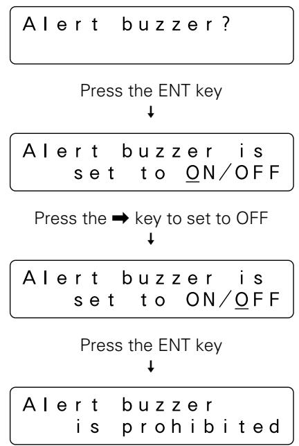
flowchart
graph TD
    A["Alert buzzer?"] --> B["Press the ENT key"]
    B --> C["Alert buzzer is set to ON/OFF"]
    C --> D["Press the ⇒ key to set to OFF"]
    D --> E["Alert buzzer is set to ON/OFF"]
    E --> F["Press the ENT key"]
    F --> G["Alert buzzer is prohibited"]
(Note that a "Alert buzzer is activated" message will be displayed if the alert buzzer is set to ON.)
6. Free message
When discs are to be inserted or removed in accordance with instructions from the host computer, messages will be displayed on the LCD message window indicating the next operation which must be performed.
For example, when a disc is to be inserted or removed from a mailslot (i.e., when auto eject function has been turned OFF), the following message will be displayed.
Press ENT-key to open mailslot
While the messages displayed on the LCD message window up until this point are the same whether a disc is being inserted or removed, since all operations after the mailslot has been opened are performed in accordance with instructions from the host computer, the changer LCD message window cannot display messages adequately.
By setting free message function ON, however, it becomes possible to have the messages displayed on the LCD message window overwritten by messages sent from the host computer, and it becomes possible to display instructions as the host computer wants to be done. It is also possible to display other information such as the name of the application controlling the changer, warning messages indicating that a disc is being written, and other information which the host computer possesses.
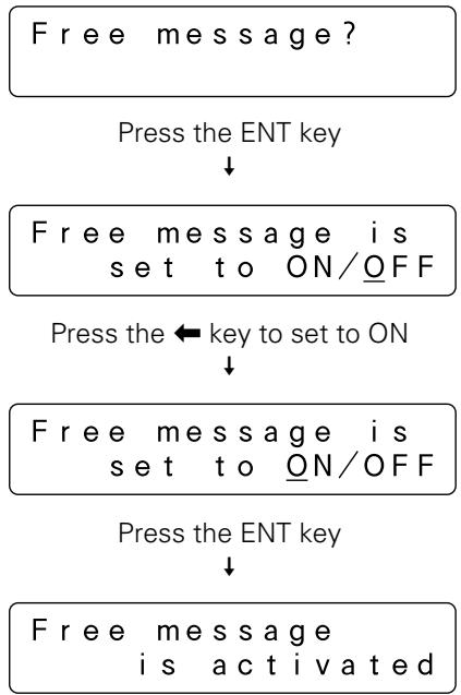
flowchart
graph TD
    A["Free message?"] --> B["Press the ENT key"]
    B --> C["Free message is set to ON/OFF"]
    C --> D["Press the ← key to set to ON"]
    D --> E["Free message is set to ON/OFF"]
    E --> F["Press the ENT key"]
    F --> G["Free message is activated"]
(Note that an "Free message is prohibited" message will be displayed if free message function is set to OFF.)
Note that even if free message function is activated, if no messages are received from the host computer, all messages displayed on the LCD message window will consist of messages from the changer itself.
Info submode
The DRM-7000/DRM-3000 stores data needed in order for system administrators to perform daily maintenance in non-volatile memories, and info submode may be used to browse these data.
< Info >
Data browser
If you press the ENT key at this point, the following menu screen will appear which makes it possible to select the type of information to be read.
Log, Contents or Run-statistics?
Move the cursor to the type of information you need and then press the ENT key.
Log
When you select log data browsing, it is possible to choose either error-log or import-log data.
Error-log or
Import-log?
Move the cursor to either "Error-log" or "Import-log" and press the ENT key to browse the corresponding log data.
- Error-log
The Error-log is a recorded history of operating errors detected by the changer. Errors are numbered from the most recent (1) up to a maximum of 32.
Moving the cursor to an error code and pressing the ENT key causes a description of the type of error in question to be displayed.
Press the ENT key gain to display detailed data regarding the type of error.
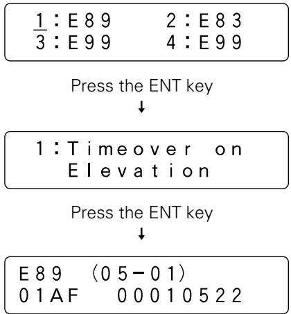
flowchart
graph TD
    A["1 : E 8 9\n3 : E 9 9"] --> B["Press the ENT key"]
    B --> C["1 : Timeover on Elevation"]
    C --> D["Press the ENT key"]
    D --> E["E 8 9 (0 5 - 0 1)\n0 1 AF 0 0 0 1 0 5 2 2"]
- Import-log
Import log is a sequential list of all disc slot numbers in which discs have been newly inserted into the changer when operating in mailslot submode (see p. 34).
The slot numbers displayed include the slot numbers not only for discs which have been added but also discs which have been replaced in mailslot submode. Note that discs in normal-type 50-disc magazines which have been added are displayed as a magazine unit.
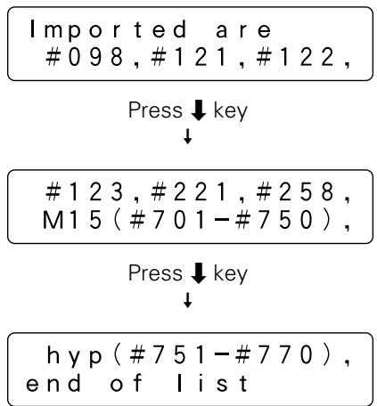
flowchart
graph TD
    A["Imported are\n#0 98, #1 21, #1 22"] --> B["Press ↓ key"]
    B --> C["#1 23, #2 21, #2 58,\nM1 5 (#7 01-#7 50)"]
    C --> D["Press ↓ key"]
    D --> E["hyp (#7 51-#7 70),\nde of list"]
Example of display for DRM-7000
Contents
Contents information of the changer may be retrieved in order to browse the status of all slots within the changer.
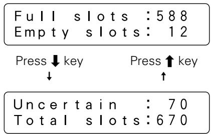
text_image
Full slots : 588 Empty slots : 12 Press ↓ key Press ↑ key ↓ ↑ Uncertain : 70 Total slots : 670Example of display for DRM-7000
Note that the number displayed under the heading "Uncertain" indicates the number of slots for which the changer is still uncertain whether the slot is empty or full.
Run-statistics
The run statistics information may be retrieved to display the amount of time or the number of times operations have been performed.
-time sum or Number of moves?
Move the cursor to either "Work-time sum" or "Number of moves" and press the ENT key to browse the corresponding data.
● Work-time sum
"PowerOn-time" may be selected in order to display the total amount of time the power has been turned on.
Power On-time or Drive work-time?
Press the ENT key
↓
Total PowerOn is
*****hour**min
"Drive work-time" may be selected to display the total amount of time each drive within the changer has been in operation.
Power On-time or Drive work-time?
Press the ENT key
↓
Drive1 works
*****hour**min
Press ↑ key ↓
Drive2 works
*****hour**min
Press key ↓
Drive3 works
*****hour**min
Note that the data indicating the total amount of time displayed under “Drive work-time” is maintained individually for each unique device ID, and that for this reason always the correct value is displayed even if a drive is reinserted into a different bay within the changer.
● Number of moves
The ↓ and ↑ keys may be pressed to display the number of any of the following four operations which have been performed.
Elevation done:
This item may be selected to indicate the number of times the elevation mechanism has been operated. Note that this information is useful as a means of determining when the elevation mechanism needs to be serviced or maintained.
Load/Unload done:
This item may be selected to indicate the number of times the loading mechanism has been operated in order to load or unload a disc into a slot or a drive. When a disc is moved from a slot to a drive, the number of load/unload operations is normally counted as two. Note that this information is useful as a means of determining when the loading mechanism needs to be serviced or maintained.
Mailslot driven:
This item may be selected to indicate the number of times a mailslot has been used. Note that an open-and-close operation is counted as one time.
Hyper driven:
This item may be selected to indicate the number of times a hyper magazine has been ejected or inserted. Note that an eject-and-insert operation is counted as one time.
Elevation done
***** times
Press ↓ key
↓
Press key
Load/Unload done
***** times
Press ↓ key
↓
Press ↑ key
↑
Mail slot driven
***** times
Press ↓ key
↓
Press key
Hyper driven
***** times
Mailslot submode
Mailslot submode is designed to use mailslot with the control panel in order to exchange, eject, or add discs.
NOTE:
Although the insertion or removal of discs may normally be performed only by the host computer in order to prevent discrepancies from arising in the database, it is permitted for the system administrator to use this mode to insert or remove discs. When doing so, however, the system administrator must make a record of the slots to which discs have been moved and, when necessary, also perform database maintenance. (Note that the slot numbers of slots for which discs have been added may be read by using the import-log in Info submode.)
$$ \begin{array}{c} \langle \text {Mail slot} \rangle \ \text {Import} \& \text {Export} \end{array} $$
If you press the ENT key at this point, the following “Swap, Remove, or Add some discs?” selection menu will appear. Move the cursor to the menu item to be selected and press the ENT key to make your selection.
$$ \begin{array}{l} \underline {{\text { Swap } , \text { Remove or }}} \ \text { Add some discs? } \end{array} $$
Swap
$$ \begin{array}{c c} \text {S I o t N o . ?} & # * * * \ & M * * - * * \end{array} $$
- Use the ↑ or ↓ keys to specify the slot number of the slot for which you wish to exchange discs and press the ENT key.
(Note that each time either one of the or keys is pressed, the slot numbers in which discs have been inserted and the slot numbers for which the changer is still uncertain whether the slot is empty or full will be shown in sequence.)
$$ \begin{array}{c} \text {Removing} \quad # * * * \ \text {as the old disc} \end{array} $$
If there is a disc in the specified slot, the disc will be carried to the mailslot, the tray will open, and the following message will be displayed.
$$ \begin{array}{l} \text {Replace discs} \ \& \text {press ENT - key} \end{array} $$
If there is no disc in the specified slot, the tray will open and the following message will be displayed.
$$ \begin{array}{l} \text {Place a new disc} \ \& \text {press ENT - key} \end{array} $$
- Place the new disc in the tray and press the ENT key. The tray will close, the following message will be displayed, and the disc will be carried to the specified slot.
$$ \begin{array}{c} \text { The new disc is } \ \text { moving to #*** } \end{array} $$
When the disc swapping operation has been completed, the message displayed on the LCD message window will return to the initial swap disc message with the next slot number corresponding to the condition described above being displayed.
To exit swap mode, press the ESC key.
Remove
$$ \begin{array}{c c} \text {D i s c N o . ?} & # * * * \ & M * * - * * \end{array} $$
- Use the ↑ or ↓ keys to specify the slot number of the disc you wish to remove and press the ENT key. (Note that discs may be removed by this mode only from slots for which it is confirmed that a disc has been inserted, and that the selection menu displayed will not change when the ENT key is pressed if there is no confirmed slot in which a disc has been inserted.)
The specified disc will be carried to the mailslot, the tray will open, and the following message will be displayed.
$$ \begin{array}{l} \text {Remove the disc} \ \& \text {press ENT - key} \end{array} $$
- Remove the disc and press the ENT key to close the tray.
When the disc has been removed, the message displayed on the LCD message window will return to the initial remove disc message with the next slot number corresponding to the condition described above being displayed.
To exit remove mode, press the ESC key.
Add
$$ \begin{array}{c c} \text {S I o t N o . ?} & # * * * \ & M * * - * * \end{array} $$
- Use the ↑ or ↓ keys to specify the slot number to which you wish to add a disc and press the ENT key. (Note that discs may be added by this mode only to slots for which it is confirmed that no disc has been inserted, and that the selection menu displayed will not change when the ENT key is pressed if there is no slot confirmed empty.)
The mailslot tray will open and the following message will be displayed.
$$ \begin{array}{l} \text {Place a new disc} \ \& \text {press ENT - key} \end{array} $$
- Place the new disc in the tray and press the ENT key. The tray will close, the following message will be displayed, and the disc will be carried to the specified slot.
$$ \begin{array}{c} \text {The new disc is} \ \text {moving to #***} \end{array} $$
When the disc has been added, the message displayed on the LCD message window will return to the initial add disc message with the next slot number corresponding to the condition described above being displayed. To exit add mode, press the ESC key.
NOTE:
If you cannot add a new disc in add mode, add the disc in swap mode instead.
Hyper submode
Hyper submode is designed to eject a hyper magazine. Since the DRM-7000/DRM-3000 is not equipped with an exclusive key to eject a hyper magazine, you must enter this mode to make the ENT key into the eject key.
$$ \begin{array}{c} \langle \text {Hyper} \rangle \ \text {Eject} \& \text {Inject} \end{array} $$
- When the ENT key is pressed, the changer will check to see if any hyper magazine discs are currently used in drives. If there are such discs currently in drives, the following message will be displayed.
$$ \begin{array}{l} \text { Host must return } \ \text { all hyper's disc } \end{array} $$
It is the host computer possessing the authority to return discs in drives to disc magazines. Therefore, if you wish to eject the hyper magazine right now, you must return to user mode first and issue a command requesting the discs be returned from the host computer.
When all the discs have been returned to the hyper magazine, the following message will be displayed.
$$ \begin{array}{c} \text {Press ENT - key} \ \text {to eject} \end{array} $$
- Pressing the ENT key will cause the following messages to be displayed and the hyper magazine to be ejected.
$$ \begin{array}{c} \text {Hyper - magazine} \ \text {is unloading} \end{array} $$
↓
$$ \begin{array}{c} \text {Hyper - magazine} \ \text {is ejected} \end{array} $$
If you wish to exit this mode without replacing the hyper magazine, press the ESC key three times to return to user mode.
Operation
If you wish to replace hyper magazines, insert the new hyper magazine. Note that the hyper magazine will be automatically loaded once it has been partway inserted, and that you should be careful not to add excessive force when inserting a magazine.
Hyper-magazine is loading
When the hyper magazine has been loaded, a unique magazine ID will be displayed together with the record of the locking mechanism.
When there are no records of the lock ever having been unlocked, the message displayed will be as follows.
Locked-state
ID=*****
When there are records of the lock having been unlocked, the message displayed will be as follows.
Uncertain-state
ID=*****
Note that the magazine will be automatically ejected if the changer is unable to read the magazine ID, and that if this happens you should try inserting the magazine again.
Probe submode
It is possible that discs have been inserted into normal-type 50-disc magazines and hyper magazines before these magazines are inserted into the changer. But it does not mean that these imported discs are ready to use because the changer and the host computer have not recognized yet which slot holds a disc or not.
Probe submode is used to examine which slot a disc is in. While this probing function is usually performed by the changer control software running on the host computer, in cases where users wish to perform this before connecting the changer to the host computer or in cases where the changer control software being used does not support such probing function, probe submode may be used instead.
<Probe> Slot initialize
- If you press the ENT key at this point, the magazine bay numbers into which magazines have been loaded will be displayed in sequence.
Initialize
slots of M1?
- Press the ↑ or ↓ key to select a disc magazine and press the ENT key to confirm your selection. The changer will examine each of the slots within the disc magazine in sequence to check whether or not a disc has been inserted.
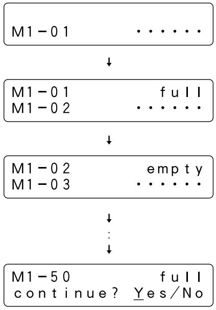
flowchart
graph TD
    A["M1 - 0 1"] --> B["↓"]
    B --> C["M1 - 0 1\nM1 - 0 2"]
    C --> D["↓"]
    D --> E["M1 - 0 2\nM1 - 0 3"]
    E --> F["↓"]
    F --> G["M1 - 5 0\ncontinue?"]
    G --> H["Yes/No"]
When all fifty slots have been probed, a message will be displayed asking if you wish to continue.
Select "Yes" to continue and "No" to quit and then press the ENT key.
Probe submode may also be used to examine which slot of the hyper magazine a disc is in, in the same manner as for 50-disc magazines.
Note that once probe submode has been used to perform a check on a given disc magazine, there is no need to ever check again for the presence or absence of discs in that magazine as long as that magazine is not removed from the changer.
Door submode
This mode is used to open the access doors to swap 50-disc magazines, to swap or add drives.
Note that it is necessary to make sure that all discs within the changer have been returned to their disc magazines or mailslot. Otherwise neither of the access doors can be opened.
This may be done by the system administrator, who should first check the status of the drives from the host computer before halting service and returning all discs.
〈Door〉
Open & Rebuild
- When the ENT key is pressed, the changer will check to see if any discs are currently used in drives. If there are any discs in drives, the following message will be displayed.
Host must return
every disc first
If this message is displayed, press the ESC key to return to user mode and issue a command requesting the discs be returned from the host computer.
When it has been confirmed that there are no discs in drives, the following message will be displayed. Move the cursor to specify the access door(s) to be opened.
Front, Rear
or Both?
- Pressing the ENT key will cause the specified access door(s) to be opened.
Front-door:Open
Rear-door : Close
NOTE:
When either of the access doors is opened, the system will automatically return to user mode. To enter a different submode, press the FUNCTION key to re-enter system administrator mode (see p. 24).
ADDING DRIVE UNITS
Any drive designed for use in the DRM-7000/DRM-3000 changer can easily be added as a new drive.
The power unit provided as standard equipment is designed to provide sufficient electrical capacity to support up to 8 drives mounted in rear bays #1 to #8. When adding additional drives to the rear bays #9 – #16 of the model DRM-7000, however, an optional additional power unit is required.
Warning about static electricity
Always be sure never to touch the contacts or ports of any connectors when installing additional drives or any other type of add-on equipment. Also be sure to touch a metallic surface on the changer before beginning the adding operations.
NOTES:
- When disconnecting drive cables that had been connected before to make the work easier, always be sure to disconnect those cables in the following order (i.e., the opposite order from that in which they are connected):
-
SCSI interface cable
-
Changer interface cable
-
Power cable
- If you wish to add a drive to a SCSI bus where the termination for an existing drive has been turned on, the termination for the new drive to be added must be turned on and the termination for the existing drive turned off.
How to add a drive
- Enter system administrator mode and enter door submode to open the rear access door.
The following message will be displayed on the LCD message window.
Front-door:Close
Rear-door : Open
- Attach add-on connector panels, if necessary
Screwdriver
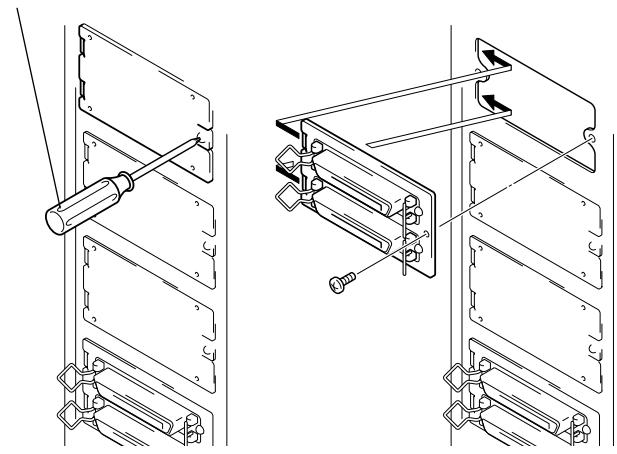
natural_image
Technical line drawing of two mechanical assembly components with mounting brackets and bolts (no text or symbols)- Place the drive on the changer guide rails, push the drive in until the lock lever on the drive shifts to the locked position. Maybe you can hear a clicking sound then.
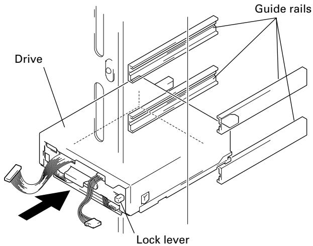
text_image
Drive Guide rails Lock lever4. Connect the power cable.
If it is difficult to work, the SCSI interface cables of other drives should be disconnected before continuing.
- When the power cable has been connected, the wiring monitor indicator on the rear of the drive (orange) will light up.
- When the termination switch of the drive is set to on, the termination indicator (green) will light up.
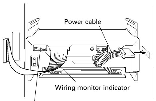
text_image
Power cable Wiring monitor indicatorTermination indicator
5. Connect the changer interface cable.
- When the changer interface cable has been connected, the wiring monitor indicator will flash at two-second intervals.
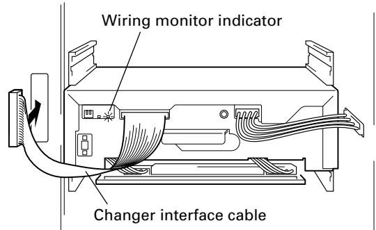
text_image
Wiring monitor indicator Changer interface cableNOTE:
Connect the changer interface cable to the connector corresponding to the bay in which the drives have been installed. (Note that labels are affixed to connectors indicating the corresponding bay number.) Note that it is extremely important to do this, as connecting the changer interface cable to a neighboring bay will result in damage to discs and the disc transport mechanism.
6. The changer will then read the drive's SCSI ID and compare the drive's settings to those of existing drives.
- If all drives have been assigned different SCSI IDs, a buzzer will sound once.
- If the same SCSI ID has been assigned to two or more drives, a buzzer will sound three times.
NOTES:
- If installed drives are to be connected to different SCSI buses, then the same SCSI ID assigned to each of the drives may be all right.
- Even if none of the drives installed within a changer has been assigned the same SCSI ID, it is necessary to check that the same SCSI ID is not assigned to other devices (e.g., hard disks) on the same SCSI bus.
7. Connect the SCSI interface cable.
If you have disconnected the SCSI interface cables of any other drives in Step 4, be sure to remember to reconnect those cables.
8. Enter system administrator mode and enter config submode (see p. 26) to check that the changer recognizes all the internal drives.
For example, three DVD-ROM drives and one DVD-R drive have been added in the rear bays beginning from Bay #1 in sequence, the following messages will be displayed.
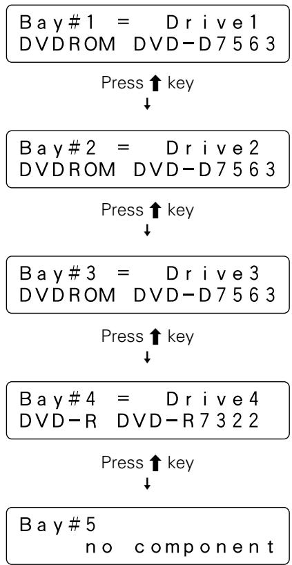
flowchart
graph TD
    A["Bay #1 = Drive 1\nDVDROM DVD-D7563"] --> B["Press ↑ key"]
    B --> C["Bay #2 = Drive 2\nDVDROM DVD-D7563"]
    C --> D["Press ↑ key"]
    D --> E["Bay #3 = Drive 3\nDVDROM DVD-D7563"]
    E --> F["Press ↑ key"]
    F --> G["Bay #4 = Drive 4\nDVD-R DVD-R7322"]
    G --> H["Press ↑ key"]
    H --> I["Bay #5\nno component"]
NOTES:
- If the changer interface cable has not been properly connected, the changer will not be able to recognize the drive at all. You should check the wiring monitor indicator located on the back of the drive. When the cables have been properly connected, the indicator ought to be flashing.
→ If the indicator is lit, check to make sure that the changer interface cable of the drive in question has been properly connected.
→ If the indicator is not lit, check to make sure that the power cable of the drive in question has been properly connected. If the cables need to be reconnected, reconnect the power cable before reconnecting the changer interface cable.
- If the drive is recognized but the model name of the drive is not displayed in the lower half of the LCD message window, disconnect all three cables and reconnect them again.
Order in which cables are to be disconnected:
- SCSI interface cable
- Changer interface cable
- Power cable
Order in which cables are to be reconnected:
- Power cable
- Changer interface cable
- SCSI interface cable
9. To view the settings for all drives which have been recognized, press the ENT key to proceed to the next layer in the message display.
- The SCSI ID, termination switch setting, and unique device ID of each drive will be read in and displayed at the same time on the same message window.
- If four drives have been connected in a daisy chain configuration and termination has been turned on for the fourth drive in the chain, the messages displayed will be as indicated below.
$$ \boxed { \begin{array}{c} \text { Bay#1 = Drive1} \ \text { DVDROM DVD - D7563 } \end{array} } $$
Press the ENT key
↓
$$ \text { sc si ID = 1 TermOFF } $$
$$ d e v - I D = 0 0 0 7 1 0 3 3 $$
Press the ESC key to return to the previous message
and then press the key
↓
$$ \text { Bay } # 2 = \text { Drive } 2 $$
$$ \text { DVDROM DVD - D7563 } $$
Press the ENT key
↓
$$ \text { sc si ID = 2 TermOFF } $$
$$ d e v - I D = 0 0 1 5 0 3 6 0 $$
Press the ESC key to return to the previous message
and then press the key
↓
$$ \text { Bay } # 3 = \text { Drive } 3 $$
$$ \begin{array}{c c} \text {DVDROM} & \text {DVD - D7563} \end{array} $$
Press the ENT key
↓
$$ \text { sc s i I D } = 3 \quad \text { Term OFF } $$
$$ d e v - I D = 0 0 0 0 0 4 0 8 $$
Press the ESC key to return to the previous message
and then press the key
↓
$$ \text { Bay } # 4 = \text { Drive } 4 $$
$$ \begin{array}{c c} \text {DVD - R} & \text {DVD - R7322} \end{array} $$
Press the ENT key
↓
$$ \text { sc si ID = 4 TermON } $$
$$ \texttt {d e v - I D} = 0 0 0 0 0 7 7 5 $$
NOTES:
- If the SCSI IDs or termination switch settings displayed differ from those which set on the backs of drives, or if a drive's device ID fails to be displayed, it is likely that the corresponding cables were improperly connected. If this happens, follow the steps outlined below to properly reconnect all the cables.
Order in which cables are to be disconnected:
- SCSI interface cable
- Changer interface cable
- Power cable
Order in which cables are to be reconnected:
- Power cable
- Changer interface cable
- SCSI interface cable
- If the device ID of a drive cannot be read, then it will be impossible for the host computer to perform automatic configuration.
10. Press the ESC key several times to return to user mode and close the rear access door.
$$ \text { s c s i I D } = 4 \quad \text { T e r m O N } $$
$$ \text {dev - ID} = 0 0 0 0 0 7 7 5 $$
Press the ESC key
↓
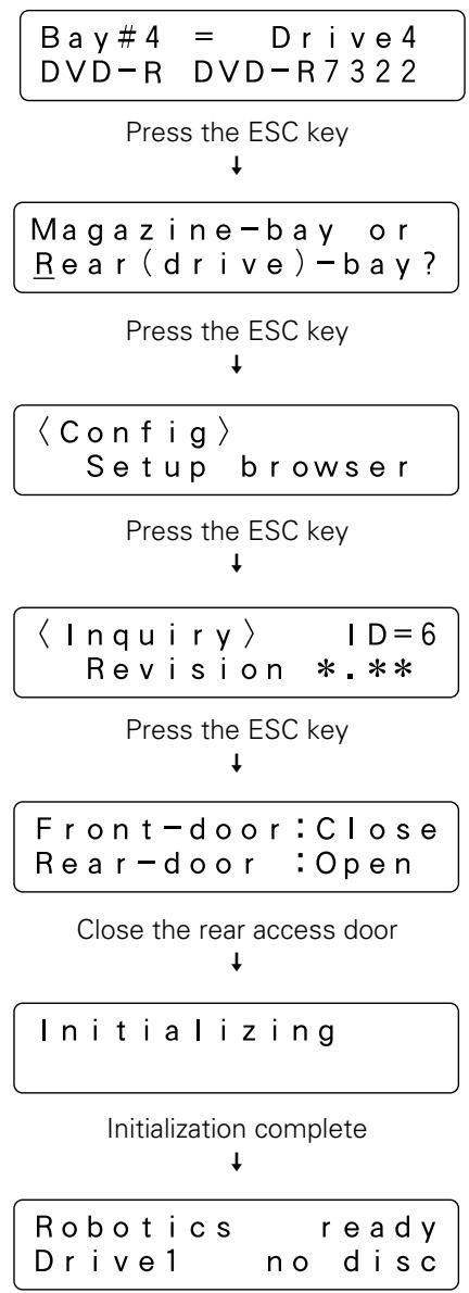
flowchart
graph TD
    A["Bay#4 = Drive4\nDVD-R DVD-R7322"] --> B["Press the ESC key"]
    B --> C["Magazine-bay or\nRear(drive)-bay?"]
    C --> D["Press the ESC key"]
    D --> E["<Config> Setup browser"]
    E --> F["Press the ESC key"]
    F --> G["<Inquiry> ID=6\nRevision *.*"]
    G --> H["Press the ESC key"]
    H --> I["Front-door:Close\nRear-door:Open"]
    I --> J["Close the rear access door"]
    J --> K["Initializing"]
    K --> L["Initialization complete"]
    L --> M["Robotics ready\nDrive1 no disc"]
As the remaining steps which must be performed may differ depending on the changer control software being used, please consult the manual for the changer control software being used for further instructions.
Also note that it may be necessary to restart the host computer before it can recognize the drives which have been added.
EXCHANGING DRIVE UNITS
Drives may be exchanged following the same procedure as that describing above for adding new drives.
Described below is the procedure to be following when exchanging drives, and it also eliminates the worry of making mistakes in the drive bay number which is to be exchanging.
NOTE:
Unless there is some special reason, the SCSI ID and termination switch settings of the drive to be installed to replace should be the same as those of the drive to be replaced.
How to exchange a drive
- Enter system administrator mode and enter door submode to open the rear access door.
The following message will be displayed on the LCD message window.
$$ \boxed { \begin{array}{c} \text {Front - door:Close} \ \text {Rear - door:Open} \end{array} } $$
- Enter system administrator mode again and enter config submode to select the rear bay.
$$ \begin{array}{l} \boxed { \begin{array}{c} \langle \text {Config} \rangle \ \text {Setup browser} \end{array} } \ \begin{array}{c} \text {Press the ENT key} \ \downarrow \end{array} \ \begin{array}{l} \text { Magazine - bay or } \ \underline {{\text { Rear(drive) - bay? }}} \end{array} \ \begin{array}{c} \text {Select "Rear" and press the ENT key} \ \downarrow \end{array} \ \begin{array}{l} \text { Bay#1 = Drive1} \ \text { DVDROM DVD - D7563 } \end{array} \ \end{array} $$
- Use the or key to select the bay in which the drive to be replaced is currently inserted.
Note that the messages actually displayed may lack some of the following information if the drive being replaced has been out of order.
$$ \begin{array}{l} \text { Bay#3 = Drive3} \ \text { DVDROM DVD - D7563 } \end{array} $$
- Make sure the wiring monitor indicator (orange). It is located on the back of the drive and ought to be flashing at half-second intervals if the drive has been selected in Step 3. Then disconnect the cables to the drive.
Order in which cables are to be disconnected:
- SCSI interface cable
- Changer interface cable
-
Power cable
-
Remove the drive.
If it is difficult to work, the SCSI interface cables of other drives should be disconnected before continuing.
-
Check the SCSI ID and termination switch settings of the drive which has just been removed, and set the SCSI ID and termination switch settings of the drive which is to be inserted in its place to the same settings.
-
Insert the new drive and connect the power cable.
-
When the power cable has been connected, the wiring monitor indicator on the rear of the drive (orange) will light up.
- When the termination switch of the drive is set to on, the termination indicator (green) will light up.
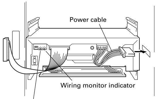
text_image
Power cable Wiring monitor indicatorTermination indicator
- Connect the changer interface cable.
- When the changer interface cable has been connected, the wiring monitor indicator will begin flashing at half-second intervals.
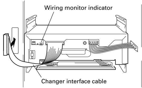
text_image
Wiring monitor indicator Changer interface cable-
Compare the SCSI ID and termination settings of the newly installed drive against those of the removed drive.
-
If the SCSI ID of the new drive is the same as that of the drive which has just been removed, the buzzer will sound once.
-
If the SCSI ID of the new drive is not the same as that of the drive which has just been removed, the buzzer will sound three times.
-
Connect the SCSI interface cable.
If you have disconnected the SCSI interface cables of any other drives in Step 5, be sure to remember to reconnect those cables.
- Check the drive device ID displayed on the LCD message window.
$$ \begin{array}{l} \text { Bay#3 = Drive3} \ \text { DVDROM DVD - D7563 } \end{array} $$
Press the ENT key ↓
$$ \begin{array}{r l} \text { sc si ID } & = 3 \quad \text { Term OFF } \ \text { dev - ID } & = * * * * * * * * * \end{array} $$
NOTES:
- If the SCSI ID and termination switch settings displayed differ from those which set on the back of the drive, or if a drive's device ID fails to be displayed, it is likely that the corresponding cables were improperly connected. If this happens, follow the steps outlined below to properly reconnect all the cables.
Order in which cables are to be disconnected:
- SCSI interface cable
- Changer interface cable
- Power cable
Order in which cables are to be reconnected:
- Power cable
- Changer interface cable
- SCSI interface cable
- If the device ID of a drive cannot be read, then it will be impossible for the host computer to perform automatic configuration.
12. Press the ESC key several times to return to user mode and close the rear access door.
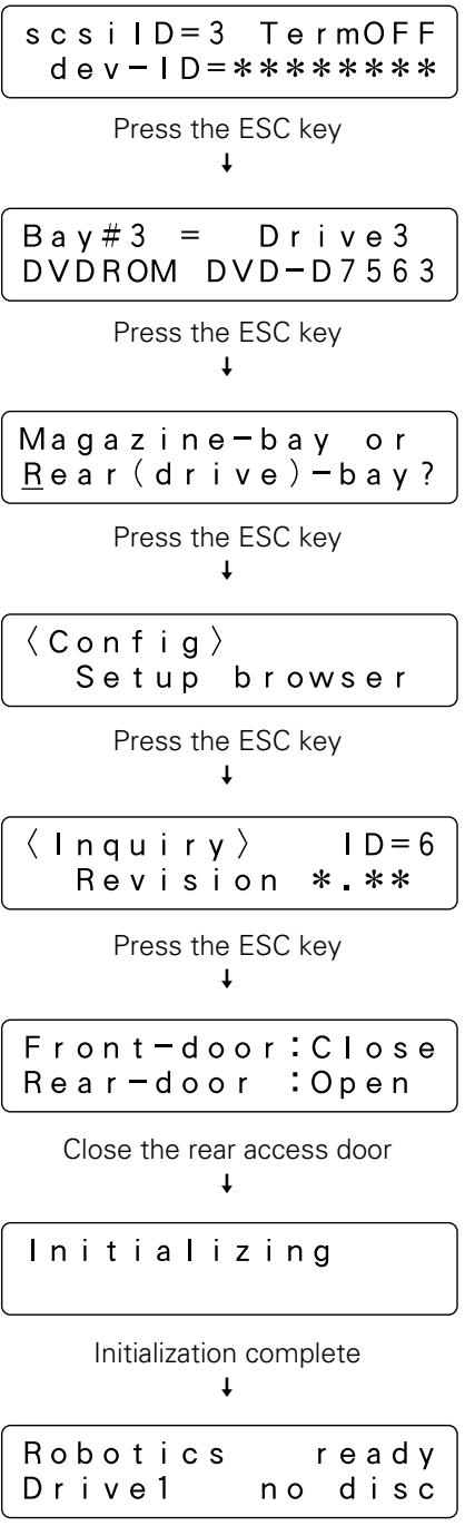
flowchart
graph TD
    A["sc si ID=3 TermOFF dev-ID=*****"] --> B["Press the ESC key"]
    B --> C["Bay#3 = Drive3 DVDROM DVD-D7563"]
    C --> D["Press the ESC key"]
    D --> E["Magazine-bay or Rear(drive)-bay?"]
    E --> F["Press the ESC key"]
    F --> G["〈Config〉 Setup browser"]
    G --> H["Press the ESC key"]
    H --> I["〈Inquiry〉 ID=6 Revision *.*"]
    I --> J["Press the ESC key"]
    J --> K["Front-door: Close Rear-door : Open"]
    K --> L["Close the rear access door"]
    L --> M["Initializing"]
    M --> N["Initialization complete"]
    N --> O["Robotics ready Drive1 no disc"]
As the remaining steps which must be performed may differ depending on the changer control software being used, please consult the manual for the changer control software being used for further instructions.
NOTE:
If you will replace drives without using the procedure described above, you must be more careful not to remove the wrong drive. In such a case, the installation procedure of the drive is the same as that described in “How to add a drive” (on p. 38), and note that the conditions under which the buzzer is sounded differ slightly.
TROUBLESHOOTING
Here are some tips for solving common problems that may be encountered. Some defects with discs or lack of experience in performing operations may result in errors being displayed or in problems which seem breakdowns. Simple mistakes or misconceptions can be corrected or cleared away by using the following table which has been provided for troubleshooting of the system administrator.
If you still find it impossible to correct a problem or if an error message refuses to go away even after consulting the list below and taking the recommended action, contact your service representative or the dealer from which you purchased the product for assistance.
Also consult the section "TO AVOID PROBLEMS" on p.12.
| Description of problem | Message display | Possible cause | Recommended action |
| Buzzer sounds when access door is open and you insert a magazine. | M**Disc Not Correct | One or more discs has not been properly placed in the slots of that magazine. | Remove the magazine and check to see if any discs are protruding. |
| Buzzer sounds when you insert a hyper magazine. | Hyper magazineDisc Not Correct | One or more discs has not been properly placed in the slots of that hyper magazine. | Remove the hyper magazine and check to see if any discs are protruding. |
| Buzzer sounds when power is first turned on and initialization begins. | E83Disc Not Correct | Some foreign object has been detected within the changer.Some discs are protruding from their magazines. | Open the access door and check to see if there is anything seems to be blocking the optical sensor. If you find it then remove it. Buzzer may stop. |
| Buzzer sounds and system refuses to enter system administrator mode when you press the FUNCTION key. | The key switch is set to the locked position. | Use the lock release key to turn the key switch to UNLOCK position. | |
| Unable to enter Mailslot or Door submode even though it is possible to enter Inquiry or Config submode. | The robotics were busy at the time you pressed a key.Switchover to these maintenance submodes has been prohibited from the host computer. | Try again after making sure the ROBOTICS BUSY indicator is off.Check to see if those operations has been prohibited from the host computer. | |
| In Mailslot submode; Swap or Add, tray opens again soon after it was closed. | Place a new disc & Press ENT-key | Mailslot was closed without placing a disc on the tray. | Press the ESC key to halt the swap disc or add disc operation. |
| In Mailslot submode; Remove, tray opens again soon after it was closed. | Remove the disc & Press ENT-key | Mailslot was closed without removing the disc from the tray. | Remove the disc from the tray. |
| As the discs in drives are not returned even after the power is turned off and back on, it is impossible to open access doors in Door submode. | The hot start function has been turned on. | Turn hot start function off and turn the power off and then back on. When the discs have been returned, re-enter Door submode and open the access door. | |
| Access door refuses to open after trying to open it in Door submode. | The access door is blocked and is unable to open. | Remove whatever is blocking the access door and try to open the access door again. | |
| Access door selection screen fails to appear when trying to open access door in Door submode. | Host must return every disc first | There are some discs remaining in drives. | Return to user mode, issue REZERO command from the host computer requesting that all discs be returned, and try to perform the operation again after all discs have been returned. |
| Hyper magazine cannot be ejected in Hyper submode. | Host must return all hyper's disc | There are some discs that from the hyper magazine remaining in drives. | Return to user mode, issue REZERO command from the host computer requesting that all discs be returned, and try to perform the operation again after all discs have been returned. |
| There exists a drive or drives which fail to be recognized by the host computer even though they have been recognized in Config submode. | ● SCSI cable has not been connected properly.● SCSI ID or termination settings have not been correctly specified.● The total length of the SCSI cables is too long.● Operator has forgotten to reboot the host computer. | ● Make sure that the SCSI cables have been connected properly.● Check to see if there is any device on the same bus with the same SCSI ID and to see that the SCSI chain has been properly terminated.● Re-configure the SCSI chain so that the total length of all the cables does not exceed the maximum allowable length.● Reboot the host computer. | |
| There exists a drive which fails to be recognized by the host computer, and the SCSI ID of the drive is set to '7' when checked in Config submode. | scsiID=7 TermOFF dev-ID= | ● The power cable for the drive in question has not been connected.● Drives have been inserted in rear bays #9 through #16 without additional power supply unit. | ● Open the rear access door and check to see if the power cable has been properly connected.● The power supplied by the power supply included as standard equipment is sufficient only for operating drives in bays #1 through #8. Reinstall the drive in one of these bays or install the additional power supply unit. |
| Unable to properly read a disc which has been inserted in a drive. | ● The disc has been inserted upside down.● The disc is soiled or scratched. | ● Check to see if the disc has been inserted upside down.● Check to see if the disc is soiled or scratched, and wipe away any soil or replace the disc. | |
| An error code is displayed on the LCD message window and the backlight flashes and the buzzer is sounded. | E88, E89,E99, etc. | A mechanical error has occurred which has made the changer unable to continue in operation. | In system administrator mode, open the access door and take whatever action is required in order to eliminate the error condition. |
| The LCD message window does not come on when the power is turned on.Pressing the operation keys has no effect. | The changer SCSI termination switch is set to OFF or the SCSI cable is not properly connected. | ● When installing is not finished, turn the SCSI termination switch to ON and turn the power OFF and ON.● If the SCSI cable is not properly connected, turn off the power. And after connection the cable properly, turn on the power again. | |
| Buzzer sounds when magazine is loaded. | ● Memory Failure● Error | Magazine's memory data is not being read correctly. | ● Remove and reinsert magazine.● If the magazine data still can't be read properly, perform a "PROBE" of the magazine, ten open and close the door. |
SPECIFICATIONS
| DRM-7000 | DRM-3000 | |
| General specifications | ||
| Description | 700-disc changer | 300-disc changer |
| Power supply | AC 100 V – 240 V, 50/60 Hz | ← |
| Power consumption | Maximum of 5.5 A (500 W) | Maximum of 3.3 A (300 W) |
| Weight of main unit (including placement fixtures) | 91.7 kg (202 lb 3 oz) | 60.6 kg (133 lb 10 oz) |
| External dimensions (including placement fixtures) | 760 x 795 x 1520 mm (W x D x H) | 760 x 729 x 872 mm (W x D x H) |
| 29-15/16 x 31-5/16 x 59-7/8 in (W x D x H) | 29-15/16 x 28-11/16 x 34-5/16 in (W x D x H) | |
| Operating requirements* | +5 °C to +35 °C (+41°F to +95°F) | ← |
| Humidity* | 5% to 85% (with no condensation) | ← |
| Storage requirements | -40 °C to +60 °C (-40°F to +140°F) | ← |
* The figures for permissible operating temperature and humidity may change depending on the components loaded. For details, consult the operating instructions for each component used.
Functional specifications
| Maximum number of discs | 720 (12-cm discs) | 320 (12-cm discs) |
| Maximum number of disc magazines | ||
| 50-disc magazines | 14 | 6 |
| 20-disc hyper magazine | 1 | ← |
| Maximum number of components | 16 | 8 |
Items included
| 20-disc hyper magazine | 1 | ← |
| Changer/drive SCSI cable | 1 | ← |
| Power cord (for use in Canada and USA) | 1 | ← |
| Power cord (for use in Japan) | 1 | ← |
| Base stabilizer | 4 | 2 |
| Screw for use in attaching Base stabilizer | 12 | 6 |
| Lock release key | 2 | ← |
| Operations Instructions | 1 | ← |
● The external design of this product or any of the above specifications may be changed at any time without prior notification.
SCSI connector specifications
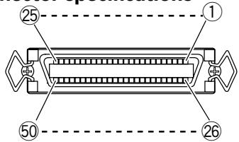
text_image
25 1 50 261) Pin layout of SCSI connectors
| Signal name | Pin No. | Signal name | |
| GROUND | 1 | 26 | -DB(0) |
| GROUND | 2 | 27 | -DB(1) |
| GROUND | 3 | 28 | -DB(2) |
| GROUND | 4 | 29 | -DB(3) |
| GROUND | 5 | 30 | -DB(4) |
| GROUND | 6 | 31 | -DB(5) |
| GROUND | 7 | 32 | -DB(6) |
| GROUND | 8 | 33 | -DB(7) |
| GROUND | 9 | 34 | -DB(P) |
| GROUND | 10 | 35 | GROUND |
| GROUND | 11 | 36 | GROUND |
| NC | 12 | 37 | NC |
| NC | 13 | 38 | TERMPWR |
| NC | 14 | 39 | NC |
| GROUND | 15 | 40 | GROUND |
| GROUND | 16 | 41 | -ATN |
| GROUND | 17 | 42 | GROUND |
| GROUND | 18 | 43 | -BSY |
| GROUND | 19 | 44 | -ACK |
| GROUND | 20 | 45 | -RST |
| GROUND | 21 | 46 | -MSG |
| GROUND | 22 | 47 | -SEL |
| GROUND | 23 | 48 | -C/D |
| GROUND | 24 | 49 | -REQ |
| GROUND | 25 | 50 | -I/O |
NOTES:
● Pin No. 12 to 14, 37 and 39 are not grounded.
● The connectors are of the shielded type.
- For details on the control commands, refer to the separate specifications manual.
2) Electrical specifications of SCSI
| Output characteristics | The signals driven by SCSI equipment present the following output characteristics. True (LOW): VOL = 0.0 to 0.4 V DC IOL = 48 mA (0.5 V DC) max. False (HIGH): VOH = 2.5 to 5.25 V DC |
| Input characteristics | The signals driven by SCSI equipment present the following input characteristics. True (LOW): VOL = 0.0 to 0.4 V DC IOL = -0.4 mA (0.4 V DC) max. False (HIGH): VOH = 2.0 to 5.25 V DC |
NOTES:
- As the SCSI interface is of the single-ended type, it should be terminated on both ends of the cable.
- The maximum recommended length of an SCSI cable is 6 meters (20 feet) (including internal wiring).
Maintenance
In order to ensure safe and proper functioning of this unit, we recommend regular maintenance. Extended service life can be expected if maintained properly.
IMPORTANT
natural_image
Technical line drawing of a mechanical device with heat dissipation and mounting bracket (no text or symbols)natural_image
Technical line drawing of a mechanical device with heat dissipation and mounting bracket (no text or symbols)natural_image
Technical line drawing of a mechanical component or housing (no text or symbols)natural_image
Line drawing of a computer chassis casing with ventilation slots and drive slots (no text or symbols)natural_image
Isometric line drawing of a computer chassis with ventilation slots and mounting brackets (no text or symbols)natural_image
Technical line drawing of a mechanical device casing with internal components (no text or symbols)natural_image
Technical line drawing of a mechanical component or housing (no text or symbols)natural_image
Technical line drawing of two connectors with a coiled cable (no text or symbols)natural_image
Coiled electrical plug with terminal connectors (no text or symbols visible)natural_image
Line drawing of a cord with multiple leads and connectors (no text or symbols)natural_image
Technical line drawing of three metal bracket components with holes (no text or symbols)DRM-3000: 2
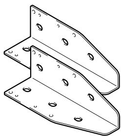
natural_image
Technical line drawing of two metal bracket components with holes (no text or symbols)natural_image
Line drawing of a key with a ring (no text or symbols)natural_image
Simple line drawing of a ring with a connector and two abstract geometric shapes inside (no text or symbols)text_image
① ② ③ ... ④ Pioneer

text_image
ESC ← ↓ → ENT FUNCTION LOCK *UNLOCK POWER ROBOTICS DRIVE MAIL.SLOT BUSY BUSY OCCUPIEDINTERIEUR DE LA PORTE AVANT

natural_image
Line drawing of a refrigerator interior with doors open, showing shelves and doorways (no text or symbols)text_image
Technical diagram of a server rack with labeled components and numbered partsINTERIEUR DE LA PORTE ARRIERE
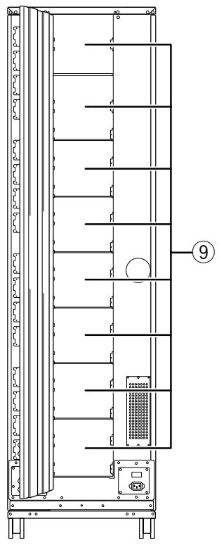
natural_image
Technical line drawing of a multi-level electronic device with internal components and mounting base (no text or symbols)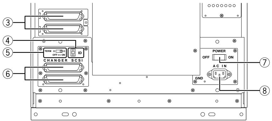
text_image
③ ④ ⑤ ⑥ CHANGER SCSI TERM OFF↔ON ID POWER ON OFF AC IN GND ⑦ ⑧natural_image
Technical line drawing of a mechanical assembly with two views (top and side), showing components like bolts, screws, and brackets (no text or symbols)natural_image
Line drawing of a printer with an arrow pointing to the front panel (no text or symbols present)Hyper-magazine is loading
↓
Uncertain-state ID=*****
flowchart
graph TD
    A["Robotics ready\nDrive1 no disc"] --> B["Robotics ready\nDrive2 no disc"]
    B --> C["Robotics busy\nDrive1 no disc"]
    C --> D["Robotics ready\nDrive2 has #205"]
    D --> E["•"]
    D --> F["•"]
$$ \begin{array}{c} \text {M7 (front - top)} \ \text {removed} \end{array} $$
<Option>
User's choice
Press ENT-key to eject hyper
Hyper I/E is set to ON/OFF
Hyper I/E is set to ON/OFF
Hyper I/E is prohibited
Log, Contents or Run-statistics?
| The new disc is moving to #*** |
| Host must return all hyper's disc |
| Press | ENT-key |
| to eject |
| Hyper-magazinesis unloading |
↓
| Hyper-magazineis ejected |
natural_image
Technical line drawing of two mechanical assembly components with bolts and brackets (no text or symbols)$$ \text {dev - ID} = 0 0 0 7 1 0 3 3 $$
$$ d e v - I D = 0 0 1 5 0 3 6 0 $$
$$ d e v - I D = 0 0 0 0 0 4 0 8 $$
$$ \text {dev - ID} = 0 0 0 0 0 7 7 5 $$
REMARQUES:
2) Electrical specifications of SCSI
CLASS 1 LASER PRODUCT LASER KLASSE 1
APPAREIL À LASER DE CLASSE 1
natural_image
Technical line drawing of a mechanical device with heat dissipation and mounting brackets (no text or symbols)● 50-Disc-Magazin (standard-type) [DRM-AF751]
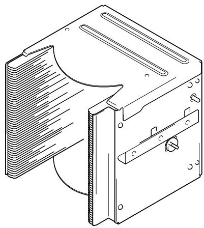
natural_image
Technical line drawing of a mechanical device with heat dissipation and mounting bracket (no text or symbols)natural_image
Technical line drawing of a mechanical component with no visible text or symbolsnatural_image
Line drawing of a computer chassis with ventilation slots and drive bays (no text or symbols)natural_image
Technical line drawing of a computer chassis with ventilation slots and mounting brackets (no text or symbols)natural_image
Technical line drawing of a mechanical device casing with internal components (no text or symbols)natural_image
Technical line drawing of a mechanical component or housing (no text or symbols)natural_image
Diagram of two connected electronic connectors with a coiled cable (no text or symbols)natural_image
Technical line drawing of three metal bracket components with mounting holes (no text or symbols)DRM-3000: 2

natural_image
Technical line drawing of two metal bracket components with mounting holes (no text or symbols)Schlüssel zur Verriegelung ... 2
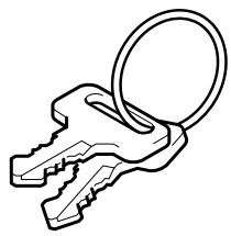
natural_image
Line drawing of a key with a ring (no text or symbols)natural_image
Pure diagram of a circular object connected to four abstract geometric shapes, no text or symbols presenttext_image
① ② ③ ④ Pioneer
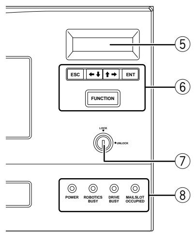
text_image
ESC ←↓ ↑→ ENT FUNCTION LOCK *UNLOCK POWER ROBOTICS DRIVE MAIL.SLOT BUSY BUSY OCCUPIEDMAGAZINFÄCHER BEI GEÖFFNETER VORDERTÜR
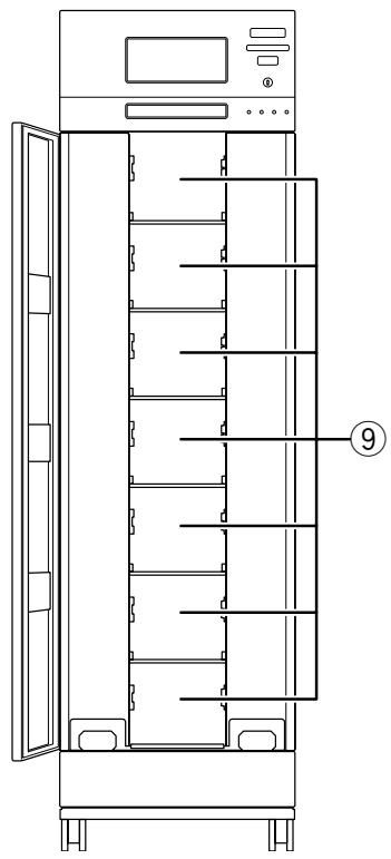
natural_image
Line drawing of a multi-level refrigerator cabinet with doors open, showing internal shelves and doorways (no text or symbols)text_image
Technical diagram of a server rack with labeled components and numbered partsMAGAZINFÄCHER BEI GEÖFFNETER
RÜCKSEITIGER TÜR
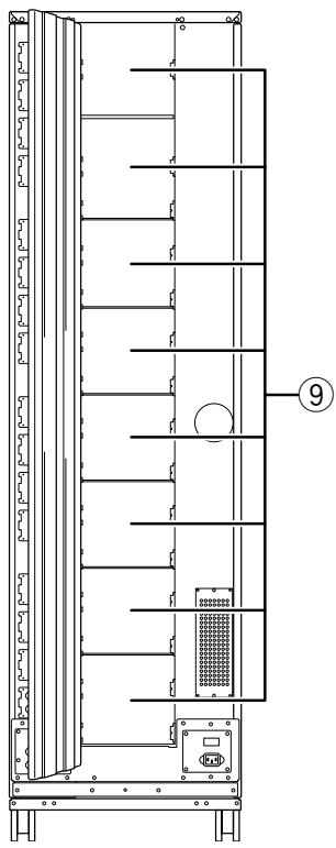
natural_image
Technical line drawing of a vertical panel or enclosure with internal compartments and a labeled component (no text or symbols present)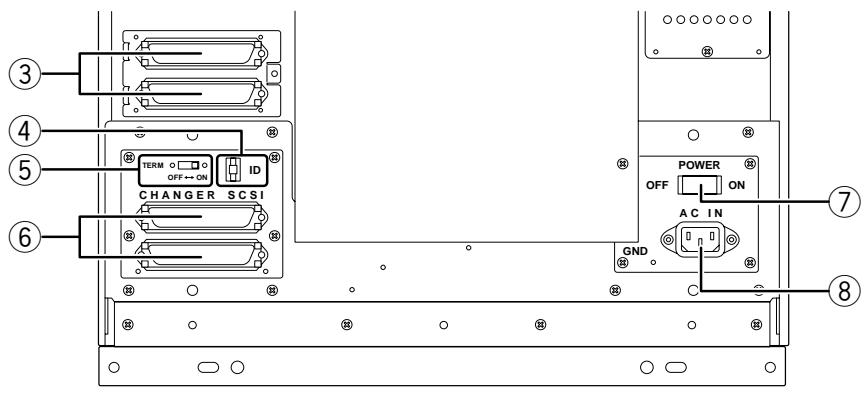
text_image
③ ④ ⑤ ⑥ CHANGER SCSI TERM OFF→ON ID POWER ON OFF AC IN GND ⑦ ⑧natural_image
Technical line drawing of two mechanical assembly components with mounting brackets and bolts (no text or symbols)natural_image
Line drawing of a printer with an arrow pointing to the front panel (no text or symbols present)flowchart
graph TD
    A["Robotics ready\nDrive1 no disc"] --> B["Robotics ready\nDrive2 no disc"]
    B --> C["Robotics busy\nDrive1 no disc"]
    C --> D["Robotics ready\nDrive2 has #205"]
    D --> E["•"]
    D --> F["•"]
$$ \begin{array}{l} \text {Disc in Drive1} \ \text {is # (M* - )} \end{array} $$
$$ \begin{array}{c} \text {M7 (front - top)} \ \text {removed} \end{array} $$
<Option>
User's choice
Auto probing is set to ON/OFF
Auto probing is set to ON/OFF
Auto probing is activated
Press ENT-key to eject hyper
Hyper I/E is set to ON/OFF
Hyper I/E is set to ON/OFF
Hyper I/E is prohibited
5. Alert buzzer (Warnsummer)
Log, Contents or Run-statistics?
Work-time sum or Number of moves?
Power On-time or Drive work-time?
Total PowerOn is
*****hour**min
Power On-time or Drive work-time?
Drive1 works
*****hour**min
Drive2 works
*****hour**min
Drive3 works
*****hour**min
$$ \begin{array}{c} \text { The new disc is } \ \text { moving to #*** } \end{array} $$
$$ \begin{array}{c} \text { The new disc is } \ \text { moving to #*** } \end{array} $$
$$ \begin{array}{l} \text {Host must return} \ \text {all hyper's disc} \end{array} $$
Hyper-magazine is loading
Locked-state
ID=*****
Uncertain-state
ID=*****
Initialize
slots of M1?
Host must return every disc first
Front, Rear or Both?
Front-door:Open
Rear-door :Close
HINWEIS:
natural_image
Technical line drawing of two mechanical assembly components with no visible text or symbols$$ \texttt {d e v - I D} = 0 0 0 7 1 0 3 3 $$
$$ \text {dev - ID} = 0 0 1 5 0 3 6 0 $$
$$ d e v - I D = 0 0 0 0 0 4 0 8 $$
$$ d e v - I D = 0 0 0 0 0 7 7 5 $$
HINWEISE:
Order in which cables are to be reconnected:
natural_image
Technical line drawing of a mechanical device with heat dissipation and mounting brackets (no text or symbols)- 50 张光盘箱(锁定式)
[DRM-AL751型]
natural_image
Technical line drawing of a mechanical device with clamps and a folded panel (no text or symbols)natural_image
Technical line drawing of a mechanical component with no visible text or symbolsnatural_image
Line drawing of a computer chassis casing with ventilation slots and mounting brackets (no text or symbols)natural_image
Isometric line drawing of a rectangular electronic component with ventilation slots and mounting brackets (no text or symbols)natural_image
Technical line drawing of a mechanical device with internal components (no text or symbols)natural_image
Technical line drawing of a mechanical component with no visible text or symbolsnatural_image
Diagram of two connected USB connectors with a coiled cable (no text or symbols)电源线(日本用) 1 条
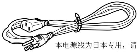
natural_image
Technical line drawing of three metal bracket components with holes (no text or symbols)DRM-3000型:2个
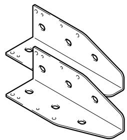
natural_image
Technical line drawing of two metal bracket components with mounting holes (no text or symbols)锁定解除钥匙 2 把
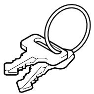
颠倒防止配件安装用螺丝
DRM-7000 型:12 个
DRM-3000 型:6 个
操作说明书 1 本
关于光盘
能够使用的光盘
natural_image
Two circular objects with a diagonal line and a prohibition symbol (no text or labels)natural_image
Pure diagram of a circular component connected to four abstract geometric shapes, no text or symbols presenttext_image
① ② ③ ④ Pioneer<操作板>
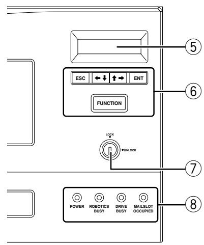
text_image
ESC ← ↓ ↑ → ENT FUNCTION LOCK +UNLOCK POWER ROBOTICS DRIVE MAILSLOT BUSY BUSY OCCUPED前门内部

natural_image
Line drawing of a refrigerator interior with doors open, showing shelves and doorways (no text or symbols)text_image
Technical diagram of a server rack with labeled components and numbered parts后门内部

natural_image
Technical line drawing of a vertical panel or enclosure with internal compartments and a labeled component (no text or symbols present)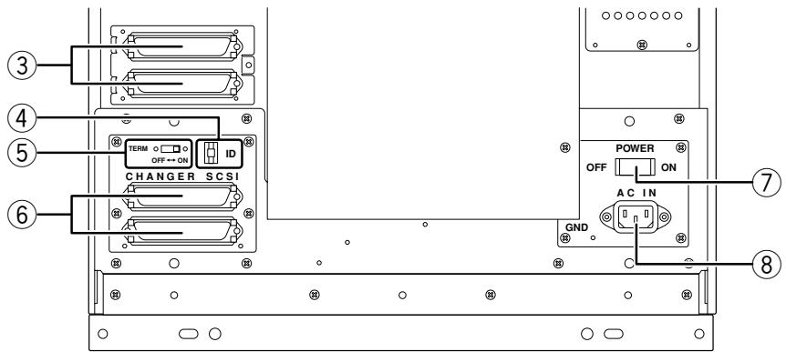
text_image
③ ④ ⑤ ⑥ CHANGER SCSI TERM OFF↔ON ID POWER ON OFF AC IN GND ⑦ ⑧① 背面板
用以安装接插板。
natural_image
Technical line drawing of two mechanical assembly components with bolts and brackets (no text or symbols)2. 安装驱动器
natural_image
Line drawing of a printer with an arrow pointing to the front panel (no text or symbols present)flowchart
graph TD
    A["Robotics ready\nDrive1 no disc"] --> B["Robotics ready\nDrive2 no disc"]
    B --> C["Robotics busy\nDrive1 no disc"]
    C --> D["Robotics ready\nDrive2 has #205"]
    D --> E[":"]
    D --> F[":"]
Magazine-bay or Rear(drive)-bay?
选择了背面间时
$$ \begin{array}{l} \text {Disc in Drive1} \ \text {is # (M* - )} \end{array} $$
$$ \begin{array}{l} \text {M1 (front - bottom)} \ \text {ID = * * * * * * * * * * *} \end{array} $$
$$ \begin{array}{c} \text {按下} \uparrow \text {键} \ \downarrow \end{array} $$
$$ \begin{array}{c} \text {M2} \ \text {ID = * * * * * * * * * * *} \end{array} $$
如果光盘箱没有被安装,则显示如下:
$$ \begin{array}{c} \text {M7 (front - top)} \ \text {removed} \end{array} $$
※ DRM-7000 型的显示例。
<Option>
User's choice
Auto probing is set to ON/OFF
按下←键来选择 ON
↓
Auto probing is set to ON/OFF
按下 ENT 键
↓
Auto probing
is activated
flowchart
graph TD
    A["Hot start?"] --> B["按下ENT键"]
    B --> C["Hot start is set to ON/OFF"]
    C --> D["按下←键来选择ON"]
    D --> E["Hot start is set to ON/OFF"]
    E --> F["按下ENT键"]
    F --> G["Hot start is activated"]
Press ENT-key to open mailslot
Press ENT-key
to eject hyper
flowchart
graph TD
    A["Alert buzzer?"] --> B["按下 ENT 键"]
    B --> C["Alert buzzer is set to ON/OFF"]
    C --> D["按下→键来选择 OFF"]
    D --> E["Alert buzzer is set to ON/OFF"]
    E --> F["按下 ENT 键"]
    F --> G["Alert buzzer is prohibited"]
Log, Contents or Run-statistics?
移动游标来选择范畴并按下 ENT 键。
Log(记录)
读取错误记录和输入记录的数据。
Error-log or
Import-log?
text_image
Imported are #098, #121, #122, 按下↓键 ↓ #123, #221, #258, M15 (#701 - #750), 按下↓键 ↓ hyp (#751 - #770), end of list※ DRM-7000 型的显示例。
Contents(目录)
读取光盘箱有关槽的信息。
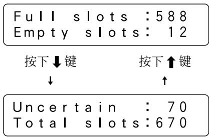
text_image
Full slots : 588 Empty slots : 12 按下↓键 按下↑键 ↓ ↑ Uncertain : 70 Total slots : 670※ DRM-7000 型的显示例。
Work-time sum or Number of moves?
移动游标来选择 “Work-time sum” 或 “Number of moves” 并按下 ENT 键。
Power On-time or Drive work-time?
按下 ENT 键
↓
Total PowerOn is
*****hour**min
Power On-time or Drive work-time?
按下 ENT 键
↓
Drive1 works
*****hour**min
按下↑键
↓
Drive2 works
*****hour**min
按下↑键
↓
Drive3 works
*****hour**min
Elevation done
***** times
按下↓键 按下↑键
↓ ↑
Load/Unload done
***** times
按下↓键
↓
按下↑键
↑
Mail slot driven
***** times
按下↓键
↓
按下↑键
↑
Hyper driven
***** times
Mailslot(邮件槽)子模式
Swap, Remove or Add some discs?
Swap(更换光盘)
S1otNo. ?    #***
    M**-**
Removing #*** as the old disc
The new disc is moving to #***
The new disc is moving to #***
Host must return all hyper's disc
Press ENT-key to eject
Hyper-magazine is unloading
↓
Hyper-magazine is ejected
Host must return every disc first
Front, Rear or Both?
Front-door:Open
Rear-door :Close
注意:
natural_image
Technical line drawing of two mechanical assembly components with mounting brackets and bolts (no text or symbols)natural_image
Technical line drawing of a mechanical device with heat dissipation and mounting brackets (no text or symbols)natural_image
Technical line drawing of a mechanical device with heat exchanger and mounting bracket (no text or symbols)natural_image
Isometric line drawing of a mechanical component or housing (no text or symbols)natural_image
Line drawing of a computer chassis with ventilation slots and drive bays (no text or symbols)natural_image
Isometric line drawing of a rectangular electronic device with ventilation slots and mounting brackets (no text or symbols)natural_image
Technical line drawing of a mechanical device with internal components (no text or symbols)natural_image
Technical line drawing of a mechanical component with no visible text or symbolsnatural_image
Technical line drawing of two connectors with a coiled cable (no text or symbols)電源コード(日本用) x1
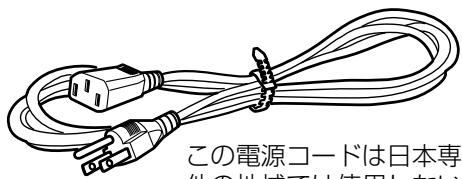
natural_image
Illustration of a coiled electrical plug with two connectors, no text or symbols present.natural_image
Technical line drawing of two U-shaped metal brackets with bolt holes (no text or symbols)DRM-3000: x2
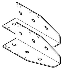
natural_image
Technical line drawing of two metal bracket components with mounting holes (no text or symbols)LOCK 解除キー x2
転倒防止金具取付用ネジ
DRM-7000: x12
DRM-3000: x6
取扱説明書 x1
保証書 x1
サービスネットワーク x1
ディスクについて
使用することのできるディスク
natural_image
Pure diagram of a circular object connected to four abstract geometric shapes, no text or symbols presenttext_image
① ② ③ ... ④ Pioneer<オペレーションパネル>

text_image
ESC ← ↓ ↑ → ENT FUNCTION LOCK *UNLOCK POWER ROBOTICS DRIVE MAILSLOT BUSY BUSY OCCUPIED前面ドア内部

natural_image
Line drawing of a refrigerator interior with doors open, showing shelves and compartments (no text or symbols)text_image
Technical diagram of a server rack with labeled components and structural layout後面ドア内部

natural_image
Technical line drawing of a vertical panel or enclosure structure with internal compartments and a labeled component (no text or symbols present)
text_image
③ ④ ⑤ ⑥ CHANGER SCSI TERM OFF → ON ID POWER OFF ON AC IN GND ⑦ ⑧natural_image
Technical line drawing of a mechanical assembly with two views (top and side), showing components like a cylindrical rod and bracket (bottom), without any text or symbols.2. ドライブを取り付けます。
natural_image
Line drawing of a printer with an arrow pointing to the front panel (no text or symbols present)flowchart
graph TD
    A["Robotics ready\nDrive1 no disc"] --> B["Robotics ready\nDrive2 no disc"]
    B --> C["Robotics busy\nDrive1 no disc"]
    C --> D["Robotics ready\nDrive2 has #205"]
    D --> E["..."]
text_image
LOCK •UNLOCK- FUNCTION キーを押す。
Magazine-bay or Rear(drive)-bay?
リアベイを選択した場合
$$ \begin{array}{l} \text {Disc in Drive1} \ \text {is # (M* - )} \end{array} $$
$$ \begin{array}{l} \text {M1 (front - bottom)} \ \text {ID = * * * * * * * * * * *} \end{array} $$
$$ \begin{array}{c} \uparrow \text {キーを押す} \ \downarrow \end{array} $$
$$ \begin{array}{c} \text {M2} \ \text {ID = * * * * * * * * * * *} \end{array} $$
$$ \begin{array}{c} \text {M7 (front - top)} \ \text {removed} \end{array} $$
※ DRM-7000 の表示例です。
<Option>
User's choice
Auto probing is set to ON/OFF
←キーを押して ON を選択する
↓
Auto probing is set to ON/OFF
ENT キーを押す
↓
Auto probing is activated
Press ENT-key to open mailslot
操作
Press ENT-key
to eject hyper
Press ENT-key to open mailslot
Log, Contents or Run-statistics?
Work-time sum or Number of moves?
Power On-time or Drive work-time?
ENT キーを押す
↓
Total PowerOn is
*****hour**min
Power On-time or Drive work-time?
ENT キーを押す
↓
Drive1 works
*****hour**min
↑キーを押す
↓
Drive2 works
*****hour**min
↑キーを押す
↓
Drive3 works
*****hour**min
Elevation done
***** times
↓キーを押す
↓
↑キーを押す
↑
Load/Unload done
***** times
↓キーを押す
↓
↑キーを押す
↑
Mail slot driven
***** times
↓キーを押す
↓
↑キーを押す
↑
Hyper driven
***** times
Mailslot サブモード
$$ \begin{array}{c} \text { The new disc is } \ \text { moving to #*** } \end{array} $$
Hyper-magazine is loading
Locked-state ID=*****
Uncertain-state
ID=*****
Initialize
slots of M1?
natural_image
Technical line drawing of a mechanical assembly with no visible text or symbols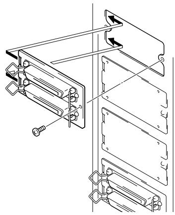
natural_image
Technical line drawing of a mechanical assembly with mounting brackets and fasteners (no text or symbols)Front-door:Close
Rear-door:Open
AFTER-SALES SERVICE FOR PIONEER PRODUCTS
Please contact the dealer or distributor from where you purchased the product for its after-sales service (including warranty conditions) or any other information. In case the necessary information is not available, please contact the Pioneer's subsidiaries (regional service headquarters) listed below:
PLEASE DO NOT SHIP YOUR PRODUCT TO THE COMPANIES at the addresses listed below for repair without advance contact, for these companies are not repair locations.
AMERICA
PIONEER ELECTRONICS (USA) INC.
CUSTOMER SUPPORT DIVISION
P.O. BOX 1760, LONG BEACH, CA 90801-1760, U.S.A.
EUROPE
PIONEER EUROPE NV
EUROPEAN SERVICE DIVISION
HAVEN 1087, KEETBERGLAAN 1, B-9120 MELSELE, BELGIUM
ASEAN
PIONEER ELECTRONICS ASIACENTRE PTE. LTD.
SERVICE DEPARTMENT
253, ALEXANDRA ROAD #04-01 SINGAPORE 159936
JAPAN AND OTHERS
PIONEER CORPORATION (HEAD OFFICE)
CUSTOMER SUPPORT CENTER
Published by Pioneer Corporation.
Copyright © 2002 Pioneer Corporation.
All rights reserved.
PIONEER ELECTRONICS (USA) INC.
Business Solutions Division: 2265 East 220th Street, Long Beach, CA 90810, U.S.A. TEL: +1-310-952-2111
Customer Support Division: 1925 East Dominguez St. Long Beach, CA 90810, U.S.A. TEL: +1-310-952-2820
PIONEER EUROPE NV
Multimedia Division: PIONEER House, Hollybush Hill Stoke Poges, Slough SL2 4QP U.K. TEL: +44-1753-789-789
PIONEER ELECTRONICS OF CANADA, INC.
Industrial Products Department: 300 Allstate Parkway, Markham, Ontario L3R OP2, Canada TEL: +1-905-479-4411
PIONEER ELECTRONICS AUSTRALIA PTY. LTD. 178-184 Boundary Road, Braeside, Victoria 3195, Australia TEL:+61-39-586-6300
PIONEER ELECTRONICS ASIACENTRE PTE. LTD. 253 Alexandra Road, #04-01, Singapore 159936 TEL: +65-6472-1111
PIONEER ELECTRONICS (CHINA) LTD. Suite 901-906, 9th Floor, World Commerce Centre, Harbour City 11 Canton Road, Tsim Sha Tsui,
Kowloon, Hong Kong TEL: +852-2848-6488