RocketRAID 4311 - NAS Highpoint - Free user manual and instructions
Find the device manual for free RocketRAID 4311 Highpoint in PDF.


| Product Type | NAS (Network Attached Storage) with RAID support |
| Brand | Highpoint |
| Model | RocketRAID 4311 |
| Number of Drive Bays | 4 |
| Compatible Drive Types | 3.5" SATA HDD / 2.5" SATA HDD/SSD |
| RAID Levels | 0, 1, 5, 10, JBOD |
| Processor | Dual-core 1.2 GHz |
| Memory | 512 MB DDR3 |
| Network Interface | Gigabit Ethernet (RJ-45) |
| USB Ports | USB 3.0 x 2 |
| Max Storage Capacity | Up to 64 TB (4 x 16TB HDD) |
| Dimensions (W x H x D) | 170 x 125 x 220 mm |
| Weight | 2.5 kg (without drives) |
| Power Supply | External 12V DC, 5A |
| Power Consumption | 35 W (typical) |
| Operating Temperature | 5°C to 35°C |
| Operating Humidity | 10% to 80% non-condensing |
| Main Functions | File sharing, backup, RAID management, media server, FTP server |
| Maintenance and Cleaning | Wipe with a dry cloth; avoid solvents. Keep vents clear. |
| Safety | Use only provided power adapter. Do not expose to water. |
| Spare Parts and Repairability | Spare drives are standard SATA. Fan and power supply replaceable. |
Frequently Asked Questions - RocketRAID 4311 Highpoint
User questions about RocketRAID 4311 Highpoint
0 question about this device. Answer the ones you know or ask your own.
Ask a new question about this device
Download the instructions for your NAS in PDF format for free! Find your manual RocketRAID 4311 - Highpoint and take your electronic device back in hand. On this page are published all the documents necessary for the use of your device. RocketRAID 4311 by Highpoint.
USER MANUAL RocketRAID 4311 Highpoint
Copyright © 2009 HighPoint Technologies, Inc. This document contains materials protected by International Copyright Laws. All rights reserved. No part of this manual may be reproduced, transmitted or transcribed in any form and for any purpose without the express written permission of HighPoint Technologies, Inc.
Trademarks
Companies and products mentioned in this manual are for identification purpose only. Product names or brand names appearing in this manual may or may not be registered trademarks or copyrights of their respective owners. Backup your important data before using HighPoint's products and use at your own risk. In no event shall HighPoint be liable for any loss of profits, or for direct, indirect, special, incidental or consequential damages arising from any defect or error in HighPoint's products or manuals. Information in this manual is subject to change without notice and does not represent a commitment on the part of HighPoint.
Notice
Reasonable effort has been made to ensure that the information in this manual is accurate. HighPoint assumes no liability for technical inaccuracies, typographical, or other errors contained herein.
Table of Contents
HIGHPOINT TECHNOLOGIES, INC....5
CONGRATULATIONS
1 - Specifications and Features ....6
2 - Kit Contents ....8
HARDWARE -- DESCRIPTION AND INSTALLATION
1 - RocketRAID Adapter layout ...... 9
2 - Installing the RocketRAID Host Adapter....15
3 - Verifying Installation 17
4 - Battery Backup....17
ROCKETRAID BIOS UTILITY
1 - BIOS Setting Overview .... 18
2 - Creating RAID Arrays 22
3 - Deleting Arrays ...... 27
4 - Monitoring the Host Adapter, Arrays and Devices ......28
5 - Maintaining Arrays .... 31
6 - Additional Functions and Settings ....36
HIGHPOINT RAID MANAGEMENT AND DEVICE DRIVER CD
1 - Creating a Driver Diskette .... 39
2 - Device Driver Installation .... 40
3 - HighPoint RAID Management Utilities (HRM) 46
CUSTOMER SUPPORT
Troubleshooting Checklist ....57
CONTACTUS....58
HighPoint Technologies, Inc.
HighPoint Technologies, long recognized as a leader in mass storage technologies specializes in the design and manufacturer of HBA (Host Bus Adapters) and HighPoint RAID IP (Intellectual Property). HighPoint provides a broad range of scalable hardware HBA's that meet the storage requirements from Enterprise to SMB (Small Medium Sized Business) to PC enthusiast.
The HighPoint RAID IP includes TerabyteArchitecture™ for (Performance, Protection and Prevention).
TerabyteStream™ - leverages the built-in Intel Xscale XOR Engine to deliver unprecedented RAID 5 and 6 performances.
TerabyteGuard™ - prevents data lose and increases data reliability with advanced hard drive inspection features utilizing bad sector repair and remapping.
TerabyteSaver ^TM - optimizes data protection with a battery backup and with write journaling thus preventing data loss.
Congratulations
You have purchased one of the highest performing and SAS/SATA hardware RAID controllers available. The RocketRAID 4300 series offers the performance and data protection features for homogeneous storage environments. The RocketRAID 4300 series meets the bandwidth requirements for high performance applications like video capture and editing, CAD/CAM and digital graphics.
Remember to visit the HighPoint websites at http://www.highpoint-tech.com and http://www.hptmac.com. There you can find information on all of HighPoint's products with FAQ's, online manuals, BIOS and driver updates.
1 - Specifications and Features
Host Adapter Architecture
•TerabyteStream™ for Blazing Performance
- TerabyteSaver™ and TerabyteGuard™ for Data Protection and Reliability
- Intel IOP 81348 (1.2GHz)
Intel IOP 81348 (800MHz)(RocketRAID RR4310/4311)
- PCI -Express x8 (compatible with x16 slot)
- 256 MB(RocketRAID 4320/4310/4311)/512MB(RocketRAID 4322/4321) of DDR II memory with ECC protection
- RocketRAID 431x directly support up to 4 SAS/SATAII drives, and up to 128 SAS devices via SAS expanders
RocketRAID 432x directly support up to 8 SAS/SATAII drives, and up to 128 SAS devices via SAS expanders
- Multi adapter support up to 4 adapters
- Intel RAID 6 (P+Q) for large capacity RAID arrays
•NVRAM for write journaling
- Battery Backup Unit (BBU) Optional
•RoHS compliant
Advanced RAID Features
•Supports RAID 0,1,3,5,6,10,50 and JBOD
•Multiple RAID array support
•Multiple logical drive support
•BIOS booting support
•BIOS PnP and BBS (BIOS boot specification) support
- Write through and write back cache
•Online Array roaming
•Online capacity expansion (OCE) and Online RAID level migration (ORLM)
- Quick and Background initialization for instant RAID configuration
•Automatic RAID rebuild
- 64bit LBA support greater than 2TB per volume
•S.M.A.R.T monitoring hard drive status for reliability
• Staggered Drive Spinup
•(MAID) spin down drives in array when idle
- ATA pass-through mode support
- Firmware update while running the Operating System
Array Monitors, Alerts and Indicators
•SMTP for email notification
•Hardware Monitor function(RocketRAID 432x)
- Alarm / Buzzer alerts for drive failure
- SAF-TE (I2C) and SGPIO enclosure management (RocketRAID432x/4310)
SAF-TE(I2C) enclosure management (RocketRAID 4311)
•SNMP for remote management(RocketRAID 432x)
- Ethernet port for (OBM) Out of Band Management (RocketRAID 432x)
•NTP (Network Time Protocol)(RocketRAID 432x)
- Intelli-VRM. (Intelligent Virtual RAID Management)
- SHI – Storage Health Inspector (S.M.A.R.T. and disk maintenance)
HighPoint RAID Management (HRM)
- Hot key (ctrl-h) boot-up RAID manager via BIOS
- Web browser-base RAID management software
- Command Line Interface (CLI)
- API library for customizing AP
Operating System Support
- Windows XP, 2003, Vista, 2008 (32 and 64-bit versions)
•Linux (Fedora Core, Red Hat Enterprise / CentOS, SuSE, Debian, Ubuntu)
•Mac OS X 10.4.x and above FreeBSD
•Freebsd
•GPL licensed driver into Linux Kernel 2.6.25
Physical Specifications
Size: (163.0mm x 68.0mm) 6.42"L x 2.68"W (RocektRAID 4322)
Size: (167.0mm x 68.0mm) 6.57"L x 2.68"W
WEMI : FCC Part 15 Class B and CE
Thermal and Atmospheric Characteristics:
Work Temperature Range: +5 C \~ + 55 C
Relative Humidity Range: 5% \~ 60% non condensing
Storage Temperature: -20C \~ +80 C
MTBF: 920,585 Hours
Electrical Characteristics:
| PCI-E | 3.3V | 12V |
| Power | 3W max | 15W max |
2 - Kit Contents
•RocketRAID Host Adapter
-User's Guide
•HighPoint RAID Management and Device Driver CD
- Internal Mini-SAS to Mini-SAS cables (RocektRAID 4310/4320/4321)
Hardware - Description and Installation
1-RocketRAIDAdapter layout
1.1 - RocketRAID 431x/4321 Adapter layout
(illustration shows the RocketRAID 4321)
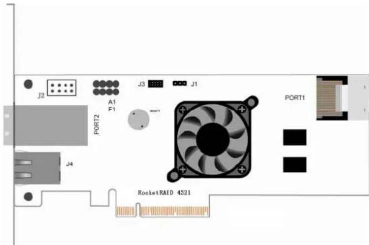
Port1- This is provided for theRocketRAID 4310/4321.
This represent the RocketRAID 4310/4321's a Internal Mini-SAS port.
Port2 -This is provided for theRocketRAID 4311/4321.
This represent the RocketRAID 4311/4321's a External Mini-SAS port.
Each port can directly support up to 4 SAS/SATA hard disks.
A1,F1
A1 is Disk Activity LED's; F1 is Disk Failure LED's. These connectors are provided for RocketRAID 4310/4321's Internal Mini-SAS port.
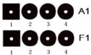
Pin - SAS/SATA channel/port stable:
| Pin NumberConnections | Pin 1 | Pin2 | Pin3 | Pin4 |
| A1 | Drive1 | Drive2 | Drive3 | Drive4 |
| F1 | Drive1 | Drive2 | Drive3 | Drive4 |
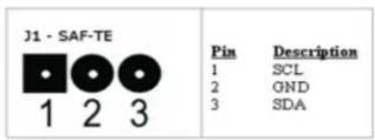
J1
This connector supports SAF-TE interface (I2C).
J2
LCD connector for LCD Panel and Push Button
Pins defined as follow:
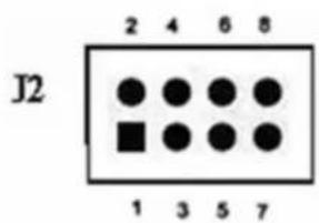
| Pin Number | Description |
| 1 | +5V |
| 2 | GND |
| 3 | LCD_INT |
| 4 | NC |
| 5 | SDA2 |
| 6 | SCL1 |
| 7 | SDA1 |
| 8 | SCL2 |
J3 (BBU connector)
Connector for HPTBBU-03 (HighPoint Battery Backup Unit 03, optional part, sold separately—see "Battery Backup" for details).
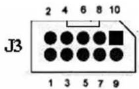
BEEP1-Speaker
Alarm (speaker): the speaker emits an audible alarm in the case of disk/array failure.
J4 - Ethernet Port (RocketRAID 4321)
Ethernet port for Out of Bound Management, support Net Time Protocol.
Cable – Internal Mini-SAS to Mini-SAS
The RocketRAID 4310/4321 includes 1 Internal Mini-SAS to Mini-SAS cables.
1.2 - RocketRAID 4320 Adapter layout
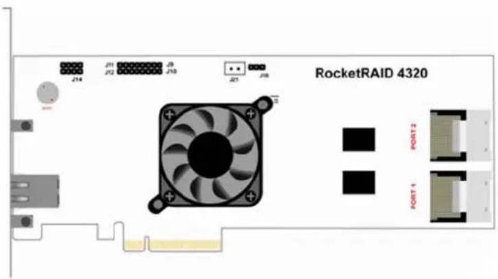
Port1- Port2 - These represent the RocketRAID 4320's 2 Internal Mini-SAS ports. Each port can directly support up to 4 SAS/SATA hard disks.
J9,J10,J11,J12
J9,J10 are Disk Activity LED's; J11,J12 are Disk Failure LED's.
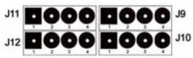
Pin - SAS/SATA channel/port stable:
| PIN NumberConnections | PIN1 | PIN2 | PIN3 | PIN4 |
| J9 | Drive1 | Drive2 | Drive3 | Drive4 |
| J10 | Drive5 | Drive6 | Drive7 | Drive8 |
| J11 | Drive1 | Drive2 | Drive3 | Drive4 |
| J12 | Drive5 | Drive6 | Drive7 | Drive8 |
J16
This connector supports SAF-TE interface (I2C).
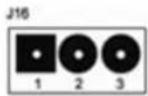
Pin definitions:
Pin 1: SCL; Pin 2: GND; Pin 3: SDA.
J14 (BBU connector)
Connector for HPTBBU-03 (HighPoint Battery Backup Unit 03, optional part, sold separately—see “Battery Backup” for details).
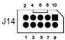
BEEP1-Speaker
Alarm (speaker): the speaker emits an audible alarm in the case of disk/array failure.
EthernetPort
Ethernet port for Out of Bound Management, support Net Time Protocol.
Cable – Internal Mini-SAS to Mini-SAS
The RocketRAID 4320 includes 2 Internal Mini-SAS to Mini-SAS cables.
1.3 - RocketRAID 4322 Adapter layout
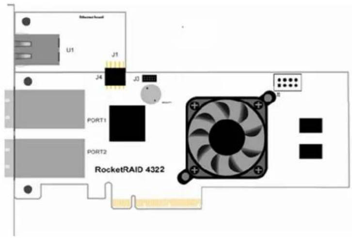
Port1, Port2
These represent the RocketRAID's 2 External Mini-SAS ports. Each port can directly support up to 4 SAS/SATA hard drives.
J3 (Battery connector)
Connector for HPTBBU-03 (HighPoint Battery Backup Unit 03, optional part, sold separately—see “Battery Backup” for details).
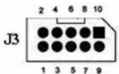
BEEP1-Speaker
Alarm (speaker): the speaker emits an audible alarm in the case of disk/array failure.
J4 (HighPoint Ethernet Board connector)
Connector for HighPoint Ethernet Board (see "Installing the HighPoint Ethernet Board" for details)
2 – Installing the RocketRAID Host Adapter
2.1 - Installing the RocketRAID 431x/4320/4321 Host Adapter
Note: Make sure the system is powered-off before installing the RocketRAID 431x/4320/4321host adapter.
- Open the system chassis and locate an unused PCI-E x8 or x16 slot.
- Remove the PCI slot cover.
- Gently insert the RocketRAID 431x/4320/4321 into the PCI-E slot, and secure the bracket to the system chassis.
- After installing the adapter, attach the Mini-SAS cables to the RocketRAID 4310/4320/4321's Mini-SAS port, and the chassis backplane. Each Mini-SAS cable supports up to 4 hard disk drives. Consult the chassis's manual for proper installation procedures.
(illustration shows the RocketRAID 4320)
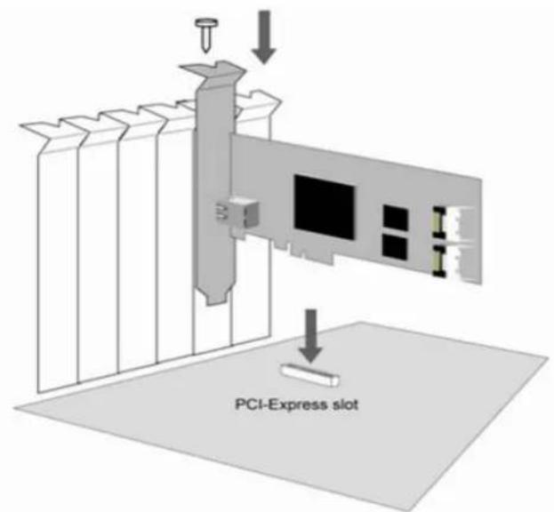
- Close and secure the system chassis.
2.2 - Installing the RocketRAID 4322 Host Adapter
Note: Make sure the system is powered-off before installing the RocketRAID 4322 host adapter.
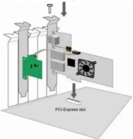
- Installing the HighPoint Ethernet Board – the following illustration shows the HighPoint Ethernet Board.
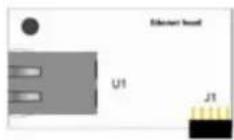
U1 is the RJ45 connector. J1 is connector for connecting the HighPoint Ethernet Board to the RocketRAID Host Adapter. If you want to use the Ethernet functions, connect the HighPoint Ethernet Board to the RocketRAID Host Adapter via connectors J4 through J1, and secure the two boards to the bracket. If you do not want to use the Ethernet function, secure the RocketRAID Host Adapter to the bracket.
-
Open the system chassis and locate an unused PCI-Express x8.
-
Remove the PCI slot cover.
-
Gently insert the RocketRAID 4322 into the PCI-Express slot, and secure the bracket to the system chassis.
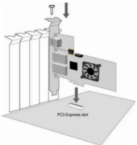
- Close and secure the system chassis
3 - Verifying Installation
Once the RocketRAID host adapter and hard drives have been installed into the chassis, boot-up the system to verify that the hardware is properly recognized.
- Power on the system. If the system detects the presence of the adapter, the RocketRAID BIOS Utility will be displayed during bootup.
- Press Ctrl+H to access the RocketRAID adapter's BIOS Utility.
The BIOS Utility will display information about hard disks attached to the adapter. Make sure all attached disks are detected by this utility. If any of the hard disks are not detected, power down the system and check the power and cable connections
4 - Battery Backup
A battery backup option is available as an optional add-on component. The battery provides additional data security in case of a critical system failure. Data normally lost during a major system fault, such as a power outage or CPU failure, which was in transit at the time of the failure (stored in the card's onboard cache), will remain viable for up to 72 hours. The battery unit can be attached to the card using the BBU CONN. Attach the BBU to the RocketRAID 431x/432x, using the cable included with the BBU unit:
(illustration shows the RocketRAID 4322)
RocketRAID BIOS Utility
The RocketRAID 431x/432x card will display it's BIOS screen during the system's boot process.
Press Control + H when prompted, to access the BIOS settings Menu.
Now, RocketRAID 432x will be used for illustrating, you will know how to do BIOS Utility of RocketRAID controllers. RocketRAID 431x are similar to RocketRAID 432x, except for channel number, Ethernet port and Hardware Monitor function.
1 - BIOS Settings Overview
The RocketRAID 432x BIOS utility is an interface that provides management commands and controller related settings.
![System Disk Array Controller Window Help Disk Channel Status Type Capacity FreeSpace VCache Model Number 1 Normal New 768.00G 0.00G On WD5000VSY UO RE2 2 Normal New 489.60G 0.00G On HDS724040KLSA80 3 Normal New 768.00G 0.00G On WD5000VSY UO RE2 4 Normal New 489.60G 0.00G On HDS724040KLSA80 5 Normal New 768.00G 0.00G On WD5000VSY UO RE2 6 Normal New 489.60G 0.00G On HDS724040KLSA80 7 Normal New 768.00G 0.00G On WD5000VSY UO RE2 8 Normal New 489.60G 0.00G On HDS724040KLSA80 Array Name Type Capacity Status OSName Task Progress (F10) Menu (TAB) Switch window [Enter] Select](/content/2026/06/1184683/images/74a69c1400a5de1762b32566e146190193cff0f4aac35c99e11467dd773f2ab3.jpg)
Using the BIOS Utility
The following keys utilized by the RocketRAID 432x BIOS utility:
F10 - press F10 to highlight the tool bar Menu.
Arrow keys – use these to move between different menu items
Enter - Open the selected toolbar command/execute the selected command.
Esc - move back to the previous menu, cancel the selected operation.
Tab - Switch between Disk and Array menus, move to next Menu item.
Space Bar – select an item (when selecting Block Size for a RAID configuration, for example).
BIOS Menu Shortcuts
The BIOS interface can also be navigated using key stroke combinations (Alt +" X"). When viewing the interface, letters highlighted in "red" represent the "X" values:
“S” – System
“D”-Disk
“A” - Array
“C”-Controller
“W” – Window
“H”-Help
“X”-Exit
Logging In
The BIOS Utility has two interface modes: User and Supervisor
The User mode can only view information about the RocketRAID card, disks and arrays.
The Supervisor mode is used to create/delete arrays, and configure RocketRAID related settings. Supervisor mode requires a password – this is the same password that you will need in order to use the Web Management interface.
Press F10 – this should bring you to the "System" toolbar command. Press Enter.
![System Disk Array Controller Window Help Disk Supervisor node User node Change password Exit [Alt+X] 7 Normal New 8 Normal New Capacity FreeSpace VCache Model Number 768.00G 0.00G On UD75000VSY UD RE2 409.50G 0.00G On HDS724040KLS880 768.00G 0.00G On UD75000VSY UD RE2 409.50G 0.00G On HDS724040KLS880 768.00G 0.00G On UD75000VSY UD RE2 409.50G 0.00G On HDS7214040KLS880 768.00G 0.00G On UD75000VSY UD RE2 409.50G 0.00G On HDS724040KLS880 Array None Type Capacity Status OSMane Task Progress (F10) Menu (TAB) Switch window (Enter) Select](/content/2026/06/1184683/images/1dbcef32dc848fc488bd81c074e99a739035ad7edb8c13b7ac49977e8b577787.jpg)
To log on as a User, use the arrow keys to highlight "User mode", and press Enter. To log on as Supervisor, select "Supervisor Mode":, and press Enter.
![System Disk Array Controller Window Help Disk Channel Status Type Capacity FreeSpace WCache Model Number 1 Normal New 768.00G 0.00G On WD5000VSY UD RE2 2 Normal New 409.60G 0.00G On HDS724040KLS880 3 Normal New 768.00G 0.00G On WD5000VSY UD RE2 4 Normal New 409.60G 0.00G On HDS724040KLS880 5 Normal New 768.00G 0.00G On WD5000VSY UD RE2 6 Normal New Enter password: OK Cancel Name Type Capacity Status OSNone Task Progress [F10] Menu [TAB] Switch window [Enter] Select](/content/2026/06/1184683/images/72e75cdc599b91368f80df4aa8e2a05c0755039a58757d6cde0c2111912403bc.jpg)
You will be asked to enter the Supervisor password.
The default password is "hpt".
BIOS Commands

System
User/Supervisor modes – interface modes
Change password - for Supervisor mode
Exit the utility – quit and exit the RocketRAID BIOS utility
Disk
Information – displays information about the select hard disks
Initialize – initialize the selected disks (required in order to use new hard disks for creating RAID arrays, disk replacement, or configuring spare disks.
Toggle Spare – configure spare disks.
Unplug – remove the selected disks (hot-swap)
Turn on write cache – enable write cache for the selected disks
Turn off write cache – disable write cache for the selected disks
Rescan – prompts the RocketRAID card to scan for new hard disks.
Array
Information - displays information about the selected RAID array
Create - Create a RAID array using the selected disks
Delete – Delete the selected RAID array
Unplug - Remove the selected RAID array (safe removal of disk members of the target array - hot-swap)
Verify - Verify the selected array (checks for parity errors)
Start Task – End Task – Stop/Pause current task
Controller
Information – View information about the RocketRAID host adapter
Eventlog – View event log entries
Setting - View and configure host adapter settings
Network - View and configure host adapter network configuration
Window
Maximize - enlarge the selected Window
Restore - restore Windows sizes to default setting
- Disk - toggle/select the Disk Window
2.Array - toggle/select the Array Window
Refresh – updates on screen information
Help
About – BIOS utility/Company information
2 - Creating RAID Arrays
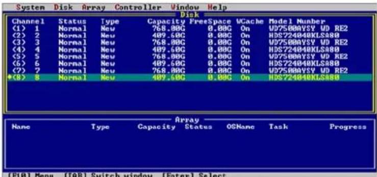
Initializing Disks:
Before creating a RAID array, the disks must be initialized. Disk initialization writes necessary RAID configuration information to the hard disks.
-
From the Disk window, highlight the target disks using the arrow keys, then select using Enter. A numeral will be displayed before each selected disk.
-
Once all target disks have been selected, select Disk from the tool bar, then highlight Initialize and press Enter.
-
The utility will display a warning, and ask you to press Y (yes) to initialize, or N (no) to cancel. Once initialized, these disks can be used to create RAID arrays. Warning: Initialization will destroy all pre-existing data on the selected hard disks. Only initialize disks that do not contain critical data. Disks only need to be initialized once.
Warning: Initialization will destroy all pre-existing data on the selected hard disks. Only initialize disks that do not contain critical data. Disks only need to be initialized once.
Disks do not have to be re-initialized after an array is deleted, or before creating a new array.
Creating Arrays:
From the Disk window, highlight the target disks using the arrow keys, then select using Enter. A numeral will be displayed before each selected disk. To de-select a disk, highlight the target disk, and press Enter once more.
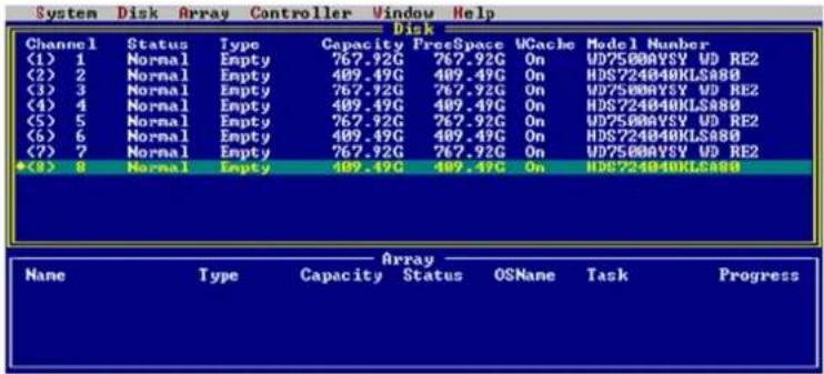
Once all target disks have been selected, select Array from the tool bar, then highlight Create and press Enter.

This will open the RAID creation Menu.
![System Disk Array Controller Window Help Disk Channel Status Type Capacity FreeSpace UCache Model Number (1) 1 N Create Array (2) 2 N Array Type Init Method (3) 3 N (<->) 1:RAID 0 (<->) Quick init (4) 4 N (<->) 2:RAID 1 (<->) Foreground (5) 5 N (<->) 3:JBOD (<->) Background (6) 6 N (<->) 4:RAID 1/0 (<->) Keep old data (7) 7 N (<->) 5:RAID 3 (<->) (8) 8 N (<->) 6:RAID 5 (<->) Keep old data (9) 9 N (None) (10) 10 RATIO 100 Cache Policy Capacity(G8) (11) None (225) (12) Write-back Block Size(16KB - 1024KB) (13) Write-through (54) Create Cancel Progress (F10) Menu ([AB] Switch window [Enter] Select](/content/2026/06/1184683/images/bfa65709feba6a8cf18252e4756e6d52a54371382c8c6cce0bce5421a1323004.jpg)
-
Array Type: First, use the Tab or arrow keys to highlight the desired RAID level, and press the Spacebar to select the Array Type. The RocketRAID 432x host adapters support RAID 0, 1, 3, 5, 6, 10, 50 and JBOD.
-
Cache Policy: Specify the Cache Policy of the array.
a. None: No cache policy set
b. Write-back – utilizes disk cache. Default setting, optimal for performance.
c. Write-through – data is written directly to disk. More secure than Write-back, but will perform slower.
- Init Method – For redundant arrays (RAID 0,1, 3, 5, 6, 10 and 50) specify the RAID Initialization method.
a. Quick init – use this option if you want to quickly create an array for testing purposes. This will clear all previous data, and will not build parity. Do not use this method if data integrity is priority.
b. Foreground – this will instruct the host adapter BIOS utility to start the initialization process immediately after creating the array. This option is recommended for data security.
c. Background – this will instruct the host adapter to initialize the array in the background, after the operating system has booted. Consider this option if you need to install an operating system to the array – this allows the array to be used immediately.
-
Name: Use the Tab or arrow keys and highlight Name. This feature allows you to name an array for reference. This is an optional setting. Press Enter to use the default name, or type in the desired name, and press Enter.
-
Capacity (GB): The adapter will display the full available capacity by default. If you want to specify the size of the array, type in the desired capacity (in Gigabytes), and press Enter. Specifying the capacity allows you to create multiple arrays using the same set of disks. Any free disk space can be used to create additional arrays, or used as a Spare disk (if the available capacity meets the requirement – see 5 - Maintaining Arrays – Spare Disks, for more information).
-
Block Size – This option allows you to specify the block size (also known as "stripe size") for specific array types (RAID 0, 1,3, 5, 6, 10 and 50). You can specify block sizes ranging from 16(KB) to 1024(KB). This allows you to tailor the array for specific applications. A balanced block size of 64 (in KB) is recommended for most applications.
-
Create / Cancel – Use Tab or arrow keys to highlight the Create or Cancel options, and press Enter. Selecting Cancel will stop the creation process. Selecting Create will create an array based on your selections, and open the Sector Size window.
![System Disk Array Controller Window Help Disk Channel Status Type Capacity FreeSpace WCache Model Number (1) 1 N (2) 2 N (3) 3 N (4) 4 N (5) 5 N (6) 6 N (7) 7 N (8) 8 N Array Type ( ) 1:RAID 0 ( ) 2:RAID 1 ( ) 3:JB ( ) 4:RA ( ) 5:RA (•) 6:RA ( ) 7:RA ( ) 8:RA Create Array Init Method ( ) Quick init (•) Foreground Sector size 512B 1K 2K 4K Cache Po ( ) None •> Writ ( ) Write-through 64 OK 24KB) Create Cancel None Progress [F10] Menu [TAB] Switch window [Eater] Select](/content/2026/06/1184683/images/331a65b1e7438d8d809066ba5b124ebbf5ee97379a6510e54c06d11b51cc5788.jpg)
- Sector Size – Also known as VSS (Variable Sector Size), this option allows you to specify the sector size of the array, for use With Windows operating systems. Older, 32-bit versions of Windows do not support volumes over 2TB in size, unless the sector size is altered. This option is not needed for Windows XP 64, Win2003 (SP1), Windows 2008, or Windows Vista. These operating systems support larger volumes, and introduce a partitioning method known as GPT (GUID Partition table). Use GPT when creating arrays over 2TB in size. For Windows 2000, or 32-bit versions of XP, refer to the following chart:
512B - Default sector size (supports up to 2TB). Use this setting for Windows OS that support GPT.
1K - Supports arrays up to 4TB
2K - Supports arrays up to 8TB
4K - Supports arrays up to 16TB
Highlight the appropriate Sector Size, and press Enter to create the array.
3 - Deleting Arrays
From the Array window, highlight the target array and press Enter. Highlight Array from the toolbar.
![System Disk Array Controller Window Help Disk Channel Status Information... 1 Norma Create... 2 Norma Delete 3 Norma Unplug 4 Norma 5 Norma 6 Norma Verify 7 Norma Start task 8 Norma Stop task Set Boot Type Capacity Status OSName Task Progress RAID5_00 RAID5 2865.99G Uninit Initializing 0.00% [FI0] Menu [TAB] Switch window [Enter] Select](/content/2026/06/1184683/images/32d6df33a5d696d2401bd82282aa2aefe267c52ee31860e5f5848f681ce41d22.jpg)
Select Delete and press Enter. The utility will display a warning message. Press Y (yes) to delete the array, or select N (no) to cancel.
![System Disk Array Controller Window Help Disk Channel Status Type Capacity FreeSpace VCache Model Number 1 Normal RAID disk 767.92G 358.49G On WD7500AVSY UD RE2 2 Normal RAID disk 409.49G 0.06G On HDS724040KLSA80 3 Normal RAID disk 767.92G 358.49G On WD7500AVSY UD RE2 4 Normal RAID disk 409.49G 0.06G On HDS724040KLSA80 5 Normal RAID disk 767.92G 358.49G On WD7500AVSY UD RE2 6 Normal RAID disk 409.49G 0.06G On HDS724040KLSA80 7 Normal 8 Normal Are you sure to delete the selected array? Yes No Array Name Type Capacity Status OSTname Task Progress RAIDS_80 RAID5 2865.99% Uninit [F10] Menu [TAB] Switch window [Enter] Select](/content/2026/06/1184683/images/051526d04b8dfd39ec2800a899f0c16cda8909f49fd7f967364d55efc62ee648.jpg)
Warning: all data stored on the array will be lost – do not delete if the array contains critical data.
4 - Monitoring the Host Adapter, Arrays and Devices
The BIOS Settings Utility allows the Administrator to check the status of the RocketRAID host adapter, and any devices (hard disks), and arrays hosted by the adapter.
Disk/Array Status
To check the status of any disk or array, use Tab to select the Disk or Array Windows, highlight the target disk/array and press enter.
Array Information – this will display the array's Name, RAID type, Block size, Sector size, member hard disks, and status.
![System Disk Array Controller Window Help Disk #Channel State Array Information 1 Nor 2 Nor 3 Nor 4 Nor 5 Nor 6 Nor 7 Nor 8 Nor Array Name RAID5_00 RAID type RAID5 Black size 64KB Sector size 512B Members: [1] CH 1 WD75000VSY VD RE2 [2] CH 2 HD5724040KLSA00 [3] CH 3 WD75000VSY VD RE2 [4] CH 4 HD5724040KLSA00 [5] CH 5 WD75000VSY VD RE2 [6] CH 6 HD5724040KLSA00 [7] CH 7 WD75000VSY VD RE2 [8] CH 8 HD5724040KLSA00 Name #R105_00 OK Progress OK](/content/2026/06/1184683/images/980b5d99f6083c0529a5f12ea2fd76d3d32678d2d129d923d0a84b296bdf66c1.jpg)
Disk Information – this will display the disk Model Number, serial number, firmware revision, capacity, and various disk related settings (NCQ, TCQ, Read Ahead, Write Cache, and Staggered Drive spinup mode).
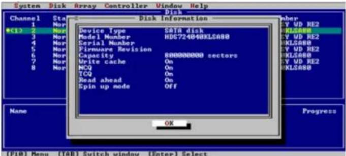
Alternately, highlight the target disk/array, then highlight either Disk or Array from the tool bar, select Information, and press Enter.
Controller Information
Highlight Controller from the toolbar, select Information, and press Enter.
Array Information – this will display the array's Name, RAID type, Block size, Sector size, member hard disks, and status.
![System Disk Array Controller Window Help Disk Controller Information Product ID RocketRAID 4322 PCI Location Bus 1, Device 1, Function 0 IOP Model IOP341 SDRAM size 256 MB Firmware Version 1.2.13.8 Battery Installed Yes Battery MB Installed Yes Battery Status Charging 85% Battery Voltage Normal Battery Temperature Normal Serial Number 1234567890ABCDEF OK D RE2 H80 D RE2 H80 D RE2 H80 Name Progress *RM1DS_00 [F10] Menu [TAB] Switch window [Enter] Select](/content/2026/06/1184683/images/4651520fb497fa09ff3acd62ff09ea93fb121bbf0c57578f16d0da8aaf2d41fa.jpg)
This option will display information about the host adapter's model (Product ID), PCI-E bus location, IO Processor model, memory, firmware revision, serial number, and the status of the BBU (battery backup unit).
Event Log
The RocketRAID host adapter automatically generates Event Log entries during the case of routine administration (creating arrays), or in the case of a critical error (disk or array failure).
Highlight Controller from the toolbar, select Event Log, and press Enter.
![System Disk Array Controller Window Help Disk Channel Status Type Capacity FreeSpace UCache Model Number Eventlog Filter: [X] Information [X] Warning [X] Error Time Type Description 2007-09-27 11:00:45 Info Test event log 1. 2007-09-27 11:01:45 Warning Test event log 2. 2007-09-27 11:02:45 Error Test event log 3. 2007-09-27 11:03:45 Info Test event log 4. 2007-09-27 11:04:45 Warning Test event log 5. 2007-09-27 11:05:45 Error Test event log 6. 2007-09-27 11:06:45 Info Test event log 7. 2007-09-27 11:07:45 Warning Test event log 8. 2007-09-27 11:08:45 Error Test event log 9. 2007-09-27 11:09:45 Info Test event log 10. Clear Prev Next Cancel [F10] Menu [TAB] Switch window [Enter] Select](/content/2026/06/1184683/images/ee9d83237f7ae9529212e44dee9b0a0c8cd6a06bae63f62e3b4083bc7efdc5b1.jpg)
Use this option to view Event Log information, including Errors (disk or array failure), Warnings (problems such as disk sector or Smart issues) and Information (such as the creation or deletion of arrays).
You can filter displayed events by using Tab to highlight the Information, Warning, and Error options towards the top of the window. Enable or disable these filter options using the Spacebar.
Use the Clear option to delete all Event Log entries. Use the Prev and Next option to scroll through log entries. Select Cancel (or press Esc) to exit the window.
5 - Maintaining Arrays
The BIOS Settings Utility provides several RAID and device related maintenance functions, including device and controller settings, Network Configuration settings (for managing the host adapter, remotely), and rebuilding broken/degraded RAID arrays.
Network Settings
This option allows the Administrator to configure Network Settings for use with the RocketRAID host adapter's Out-of-Band (OOB), and In-Band (IB) Management functions.
Highlight Controller from the toolbar, select Network, and press Enter.
![System Disk Array Controller Window Help Disk •Channel Status Type Capacity FreeSpace VCache Model Number 1 Normal RAID disk 767.92G 358.49G On WD75000VSY WD RE2 2 Normal RAID Network Settings HDS724040KLSA80 3 Normal RAID [X] Use automatic config WD75000VSY WD RE2 4 Normal RAID 5 Normal RAID IP address WD75000VSY WD RE2 6 Normal RAID Network mask HDS724040KLSA80 7 Normal RAID DNS server 8 Normal RAID Gateway address WD75000VSY WD RE2 Mac address HDS724040KLSA80 Name Type Task Progress •RAIDS_00 RAIDS OK Cancel Initializing 0.00%](/content/2026/06/1184683/images/819520186359ee6179575f87eb2cf614028216cd97071572ebe417cc32b50ae7.jpg)
This option will display information about the host adapter's network settings. By default, these settings are configured automatically, based on information provided by the local network. To manually configure these settings, use the Tab or arrow keys and highlight Use automatic config, and press the Spacebar. Type in the appropriate network settings, highlight OK, and press Enter.
Controller Settings
Highlight Controller from the toolbar, select Settings and press Enter.
![System Disk Array Controller Window Help Controller Setting [X] Enable audible alarm [ ] Enable staggered spin up Number of drives per spin up Delay between spin up (seconds) [ ] Spin down idle disk (minutes) [ ] Enable automatic rebuild Rebuild priority ( ) lowest ( ) low ( ) medium ( ) high ( ) highest [X] Provide INT13 support [X] Use single BCU entry [X] Stop on error [X] NCQ [ ] SGPIO for LED control OK Cancel Number VSY WD RE2 40KLSA80 VSY WD RE2 40KLSA80 VSY WD RE2 40KLSA80 VSY WD RE2 40KLSA80 Progress zizing 0.00% Name *RAID5_00](/content/2026/06/1184683/images/fd939babeccdfff94bd53994dfc7b32f834723ff3fe9ea848ecd738137c52b27.jpg)
[F10] Menu [TAB] Switch window [Enter] Select
Use the tab and arrow keys to select each item, and the Spacebar to enable/disable the target option.
- Enable Audible Alarm – enables/disables card's alarm (beeper)
- Enable Staggered drive spinup – enable/disable staggered drive spin-up. Disabled by default. If enabled, the host adapter will spin disks in sequence (one disk, every "x#" of seconds – enter the desired value). Some hard disks do not support this setting – consult the hard disk's documentation for more information.
- Spin down idle disk – If enabled, the host adapter will power down idle (inactive) disks/arrays based on the allotted time. Specify the value (in minutes)
- Rebuild Priority – This option is provided for redundant arrays. This setting determines the priority of rebuilding arrays in regards to other system tasks.
-
Provide INT13 support – enable or disable INT13 (the host adapter's boot function). Disabling this setting may resolve motherboard BIOS related issues in cases where the card cannot be loaded into memory properly (option ROM/out of memory errors).
-
Use Single BCV Entry – also related to motherboard BIOS settings (troubleshooting)
- Stop on Error – Enabled by default. If disabled, the host adapter BIOS menu will bypass array or device errors when booting the system.
- NCQ – enable/disable NCQ (native command queuing)
Device Settings
These options allow the administrator to enable or disable hard disk cache related settings.
From the Disk Window, highlight the target disk and press Enter. Highlight Disk from the toolbar:
![System Disk Array Controller Window Help Channel1 Information... (1) 1 2 Initialize 3 Toggle Spare 4 Unplug 5 Turn n write cache 6 Turn off write cache 7 Rescan [Alt+R] Space UCache Model Number 8.49C On UD7500AYSY WD RE2 0.05C On HDS724840KLSA8B 8.49C On UD7500AYSY WD RE2 0.05C On HDS724840KLSA8B 0.49C On UD7500AYSY WD RE2 0.05C On HDS724840KLSA8B 8.49C On UD7500AYSY WD RE2 0.05C On HDS724840KLSA8B Array Name Type Capacity Status OSMane Task Progress RAIDS_80 RAID5 2865.99G Uninit Initializing 0.00% [P10] Menu [TAB] Switch window [Enter] Select](/content/2026/06/1184683/images/0d2c47b20a7215b8ec405f62fba85e65bc686b47b06d690c9893db0fda060d93.jpg)
Turn on Write cache – enables the use of the hard disk cache. This is the recommended setting
Turn off write cache – disable the use of the hard disk cache. Use this setting for troubleshooting hard disks, or for testing purposes. Disabling disk cache will lower performance
Spare Disks
Spare Disks are used to automatically rebuild Redundant RAID arrays in the case of disk failure. As with creating RAID arrays, disks must be initialized before they can be used as spares. To set a hard disk to act as a Spare Disk, switch to the Disk window, use the arrow keys to select the target disk from the list of initialized disks, and press Enter.
Highlight Disk from the toolbar, then select Toggle Spare, and press Enter.
![System Disk Array Controller Window Help Channel (1) 1 2 3 4 5 6 7 8 Information... Initialize Toggle Spare Unplug Turn on write cache Turn off write cache Rescan [Alt+R] cSpace WCache Model Number S8.49G On WD7500AYSY WD RE2 B.06G On HDS724040KLSA80 S8.49G On WD7500AYSY WD RE2 B.06G On HDS724040KLSA80 S8.49G On WD7500AYSY WD RE2 B.06G On HDS724040KLSA80 S8.49G On WD7500AYSY WD RE2 B.06C On HDS724040KLSA80 Rescan [Alt+R] Name Type Capacity Status OSName Task Progress *RAID5_80 RAID5 2865.995 Uninit Initializing 0.00% (F10) Menu [TAB] Switch window [Enter] Select](/content/2026/06/1184683/images/c3275533d82d73a1140ac0ebaabc1c794db9f66b18a279c45c784d8f269bae0f.jpg)
To remove a spare, follow the same procedure. From the Disk window, select the target Spare disk and press Enter. Highlight Disk from the toolbar, select Toggle Spare and press Enter.
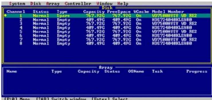
Generally, single disks are designated to act as spares (disks that are not configured into RAID arrays).
However, in some instances, disks that are members of RAID arrays may also be assigned to act as a spare disk. If the disks in question are part of a RAID array that did not utilize the full available capacity at the time of creation, these disks may be used as spares. For example: a RAID 0 array was created between two 200GB hard disks, but only 200GB of space (out of a grand total of 400GB), was assigned to that array. In this example, 200GB of disk space remains unallocated. This unallocated space allows these disks to be set as spares for a separate redundant array that meets the capacity requirement (200GB or less).
Verifying Arrays
Routine RAID verification is essential for maintaining the integrity of data stored on redundant RAID arrays. The RocketRAID BIOS utility allows you to manually verify RAID arrays.
From the Array window, highlight the target array and press Enter. Highlight Array from the toolbar, select Verify, and press Enter.
![System Disk Array Controller Window Help Disk Channel Status Information... 1 Norma Create... Unplug 2 Norma Delete Unplug 3 Norma Unplug 4 Norma Verify Start task Step task 5 Norma Set Boot 6 Norma 7 Norma Start task Step task 8 Norma Set Boot Array Name Type Capacity Status OSName Task Progress *RAIDS_00 RAIDS 2065.99G Uninit (F10) Menu (TAB) Switch window [Enter] Select](/content/2026/06/1184683/images/cfd48d9b30eaa7c552ba0242b71b943d0eabc12f695fd7174775e60455ff38c6.jpg)
Progress will be displayed towards the lower right-hand corner of the screen (percent complete).
To stop or pause the verification process, select Stop Task from the same menu. To continue the verification process, select Start Task.
6 - Additional Functions and Settings
Set Boot
Highlight the target array from the Array window and press Enter. Highlight Array from the toolbar:
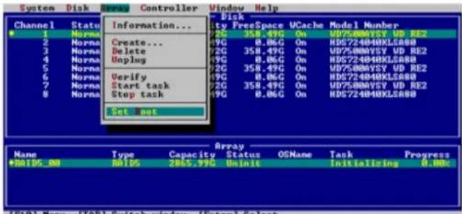
Note: Use this option to set an array to act as the boot device. The selected array will act as the boot "disk", if the motherboard's BIOS instructs the card to act as the system's boot device.
Hot-Swap
The BIOS utility provides several options that allow the administrator to add or remove disks and arrays, without powering down the system.
Adding/removing Disks
To prepare a disk for removal, first highlight the target disk using the Disk window and press Enter. Highlight Disk from the toolbar, select Unplug, and press Enter.
![System D1X Array Controller Window Help Channel (1) 1 2 3 4 5 6 7 8 Information... Initialize Toysle Spare Typing Turn on write cache Turn off write cache Rescan [Alt+R] Space UCache Model Number 8.49G On V075808VSY UD RE2 8.49G On HD5724040KLSA8B 8.49G On V075808VSY UD RE2 8.49G On HD5724040KLSA8B 8.49G On V075808VSY UD RE2 8.49G On HD5724040KLSA8B 8.49G On V075808VSY UD RE2 8,06G On HD5724040KLSA8B 8.49G On V075808VSY UD RE2 8.49G On HD5724040KLSA8B Array Name Type Capacity Status OSNone Task Progress #RAIDS_8B RAID5 2065,99C Uninit (F10) Menu (TAB) Switch window (Enter) Select](/content/2026/06/1184683/images/1e41dce76e35dc12dd45d8048782a981985bbab215e09e771498d873ef0a2a23.jpg)
To add a disk, install the hard disk, then highlight Disk from the toolbar, select Rescan, and press Enter.
Note: After installing the disk into the hot-swap capable drive bay, wait several seconds to allow the disk to fully power on, before using the Rescan command.
Adding/removingArrays
To prepare a RAID array for removal, highlight the target array using the Array window and press Enter. Highlight Array from the toolbar, select Unplug, and press Enter.
![System Disk Array Controller Window Help Channel Status Information... 1 Norma 2 Norma 3 Norma 4 Norma 5 Norma 6 Norma 7 Norma 8 Norma Information... Create... Delete nplug Verify Start task Stop task Set Boot Disk lty FreeSpace VCache Model Number 2G 358.49G On WD7500AVSY UD RE2 2G 0.05G On HDS724040KLSA80 2G 358.49G On WD7500AVSY UD RE2 2G 0.05G On HDS724040KLSA80 2G 358.49G On WD7500AVSY UD RE2 2G 0.05G On HDS724040KLSA80 2G 358.48G On WD7500AVSY UD RE2 2G 0.05G On HDS724040KLSA80 Array Name Type Capacity Status OSNone Task Progress RA1DS_00 RAID5 2865.99G Uninit - [F10] Menu [TAB] Switch window [Enter] Select](/content/2026/06/1184683/images/4a23e8f1c6fb23e6393c91128cfd9bbc5e118f2a0cbc2f36b1f4e923158bc208.jpg)
The interface will notify you when the disk can be removed.
To add an array, install all of the RAID hard disks, then highlight Window from the toolbar. Select Refresh, and press Enter.
Note: After installing the hard disks into the hot-swap capable drive bays, wait several seconds to allow the disks to fully power on, before using the Rescan command.
Window Menu
The Window menu provides several view options.
![System Disk Array Controller Window Help Channel Status Type Capac (1) 1 Normal RAID/Spare 767. 2 Normal RAID disk 409. 3 Normal RAID disk 767. √1. Disk 4 Normal RAID disk 409. 2. Array 5 Normal RAID disk 767. 6 Normal RAID disk 409. Refresh 7 Normal RAID disk 767. 8 Normal RAID disk 409.49G 0.05G UCache Model Number On WD75000Y5V WD RE2 On HDS724040KLSA88 On WD75000Y5V WD RE2 On HDS724040KLSA88 On WD75000Y5V WD RE2 On HDS724040KLSA88 On WD75000Y5V WD RE2 On HDS724040KLSA88 Array Name Type Capacity Status OSNone Task Progress RAIDS_00 RAID5 2865.99G Uninit [F10] Menu [TAB] Switch window [Enter] Select](/content/2026/06/1184683/images/1692ee2d6bd648e87e9f1d027387d7346dd0a6813ff549fa709000bcc047ce30.jpg)
- Maximize – enlarge viewing area of the selected window (Disk or Array)
- Minimize – reduce the viewing area of the selected window)
- Disk – selects the Disk window
- Array – selects the Array window
- Refresh – scans for any hardware changes (used when adding arrays or disks to the card)
HighPoint RAID Management and Device Driver CD
Each retail box includes a copy of the HighPoint Products Software CD.
This CD can be used to generate driver diskettes, and install the HighPoint RAID Management Utility Suite for a variety of operating systems.
1 - Creating a driver diskette
Windows 2000, 2003 and several distributions of Linux and FreeBSD require driver diskettes when installing the operating system directly to a disk or array hosted by the Rocket RAID host adapter.
To create a driver floppy diskette:
-
Insert the CD into the system's CD/DVD drive. The program should start automatically.
-
Insert a blank floppy diskette into the system's floppy drive.
-
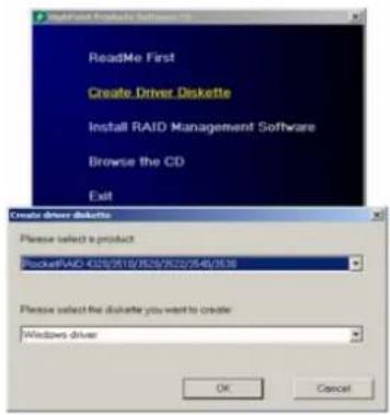
Click on "Create Driver Diskette".
-
Click on the "Please Select a Product" drop-down button, and select the appropriate host adapter model from the list.
-
Click on the "Please Select the Diskette you want to create" drop-down button, and select the desired operating system from the list.
-
Click on the "OK" button to create the driver diskette.
2 - Device Driver Installation
We recommend visiting the RocketRAID download page for the latest Windows Device Driver updates:
you can access below website:
http://www.highpoint-tech.cn/China/biosc.htm
Then, RocketRAID controllers are represented, you can press relevant Link to access Product Driver.
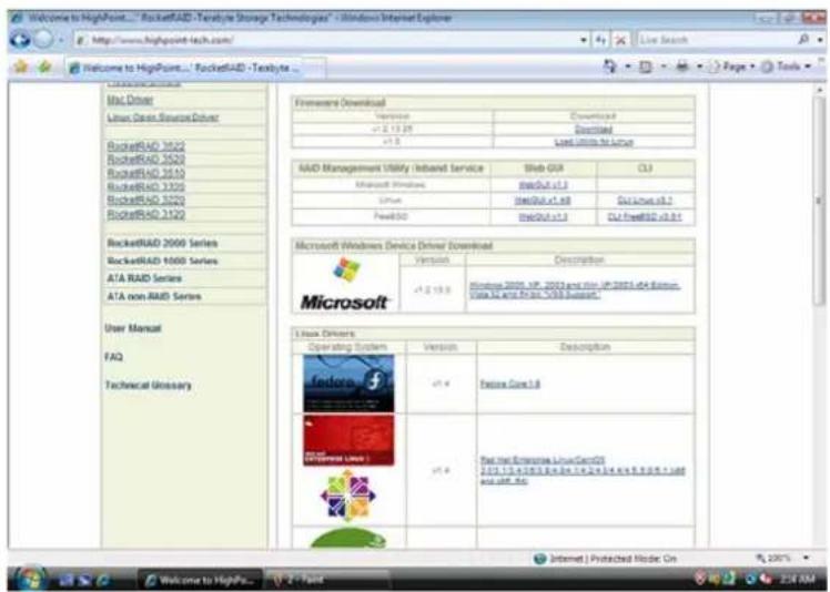
Drivers are posted in .zip archive format. Most Windows operating systems will recognize this archive format, natively. Double click the driver download to view and extract their contents. Drivers can be extracted and/or copied to various media.
Windows Driver Installation (Win2000, XP, Win 2003)
Before installing the RocketRAID 432x host adapter's device driver, make sure the host adapter and all required hard disks have been installed into the system's chassis/disk enclosure. If you are working with a supplied driver, or driver download, you will want to extract the contents directly to a directory of your choice (or device). You will need to browse to this location, in order to load the driver (see step 2, below).
Installing the RocketRAID 431x/432x driver for an existing Windows system.
After the operating system has booted, Windows will automatically detect the RocketRAID 431x/432x host adapter, and request that a device driver be installed. To install the device driver, follow the steps outlined below:
- When the “Found New Hardware Wizard” window appears, select “Install from a list or specific location (Advanced)”, and click Next to continue.
- Click on the “Include this location in the search” option, and select the system’s floppy drive (generally Disk A). Next, insert the Driver Installation diskette into the system’s floppy drive, or select Browse, and browse to the location of the driver. If you are using the RocketRAID 431x/432x software CD, the drivers are located in RR3xxx_4xxx – Windows –Driver–Windows (then select the appropriate folder).
- Windows may display a warning message that states the driver has "not been signed". Select "Continue Anyway", then click Finish when prompted. When windows asks to reboot the system, choose No.
- remove the Driver Installation diskette from the floppy drive, then Shut down and restart the computer.
Installation Verification
After the driver has been installed, and the system has been restarted:
- Click the Start button, then right-click the "My Computer" icon. Select the Properties item from the pop up menu.
- In the popup window, click the "Hardware" tab then click Device Manager button.
- Double click the "SCSI and RAID controllers" entry. If the RocketRAID 431x/432x device entry is not displayed, or there are "?" or "!" marks displayed near the RocketRAID 431x/432x entry, the driver has not been installed properly. Delete the entries and reinstall the driver.
Installing the RocketRAID driver during a fresh Windows installation
- After booting from the Windows CD or DVD-ROM, when the Windows Setup blue screen appears, look towards the bottom of the screen. Windows will prompt you to press the F6 key if you want to install a third party SCSI or RAID driver. Press the F6 key at this time.
- The setup procedure will continue, and will later instruct you to press the "S" key to specify additional adapters. Press the "S" key as instructed.
- Next, the setup program will prompt for the insertion of the driver diskette. Please insert the driver diskette, and then press ENTER to continue.
- The next window will display several driver options. Please select the driver for the corresponding operating system, and press ENTER to continue.
Windows Vista/2008 Driver Installation
Installing the driver during a fresh Windows Vista/2008 installation
- Boot from Windows Vista DVD.
- When the screen "where do you want to install Windows" appears, click "Load driver" and browse for the driver location. Windows Vista will accept install drivers from various sources: floppy diskette, USB flash disk or CD. If you are using the RocketRAID 431x/432x software CD, the drivers are located in RR3xxx_4xxx - Windows-Driver - VistaWin2008 - 32 (or 64, if you are running a 64-bit version of the operating system).
- Select the RocketRAID 431x/432x controller driver, and click "Next".
- The driver is now installed – you can now commence with the standard OS installation procedures.
Installing the driver for an existing Windows Vista/2008 system
- Intall the RocketRAID 431x/432x host adapter into the PC, then boot up Windows.
- Windows should automatically detect the card, and display the "Found New Hardware" wizard pop-up window. Select "Locate and install driver software". When Windows asks: "Windows needs your permission to continue", select "continue".
- Select “I don’t have disc, show me other options” and then select “Browse my computer for driver software”.
- Specify the location of the driver and click "Next. If you are using the RocketRAID 431x/432x software CD, the drivers are located in RR3xxx_4xxx - Windows-Driver - VistaWin2008 - 32 (or 64, if you are running a 64-bit version of the operating system).
- When asked: "Would you like to install this driver software?" select "Install".
- Reboot the system when prompted. The RocketRAID 431x/432x will be available for use after Windows reboots.
Installation Verification
After the driver has been installed, and the system has been restarted:
-
Click the Start button, then right-click My Computer icon. Select the Properties item from the popup menu.
-
In the popup window, select Hardware tab and then click Device Manager button.
-
Double click the "Storage Controllers" entry. If the RocketRAID 431x/432x device entry is not displayed, or there are "?" or "!" marks displayed near the RocketRAID 431x/432x entry, the driver has not been installed properly. Delete the entries and reinstall the driver.
Linux and FreeBSD Device Driver installation
The RocketRAID 431x/432x host adapter is fully GPL compliant, and is natively support by Linux kernel 2.6.25x. Linux distributions that utilize this kernel (and all later releases) will automatically recognize the host adapter, and do not require driver installation.
In addition, binary and source driver updates are routinely posted for a variety of older Linux operating systems including past versions of Red Hat Enterprise, CentOS, OpenSuSE, and Fedora Core.
Drivers are also available for several FreeBSD revisions, and are available from the same support page:
you can access below website:
http://www.highpoint-tech.com/USA/bios.htm
Then,RocketRAID controllers are represented,you can press relevant Link to access Product Driver.
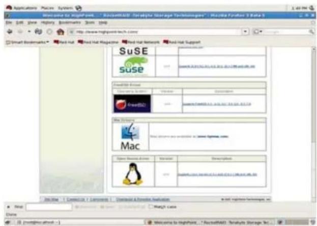
Several driver sets are included with the RocketRAID 431x/432x Software CD.
Each binary driver and source package includes an installation guide (.pdf format).
Linux Driver sets:
RR3xxx_4xxx/Linux directory.
FreeBSD Driver sets:
RR3xxx_4xxx/FreeBSDdirectory.
3 - HighPoint RAID Management Utilities (HRM)
The HighPoint RAID Management Utility Suite, also known as "HRM", includes several user interface options. The latest version of the Web Management utility user manual, is available from our website.
Windows Operating Systems – Installing the Web-based Management Utility
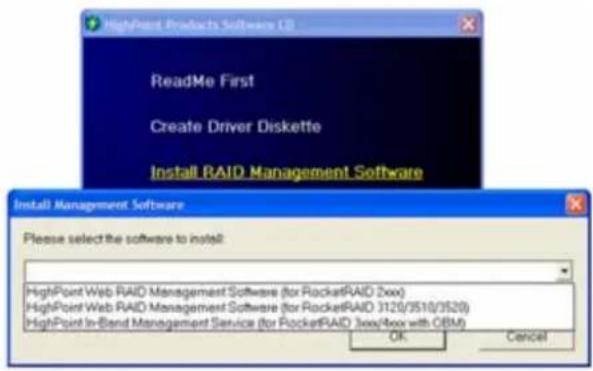
Click on "Install RAID Management Software".
Select the desired software from the drop down menu, and click on the "OK" button.
Red Hat Enterprise/CentOS, Fedora Core, Open SuSE – Installing the Web-based Management utility
Linux operating systems that support .rpm packages, allow you to double-click the HighPoint Web RAID Management .rpm file to start the installation process.
- Copy the Web RAID Management package from the RocketRAID 431x/432x Software CD, to the desktop of the Linux operating system. The .rpm file is located in HighPoint RAID Management Software – RR3xxx_4xxx - Linux – WebGui-Linux.tbz.
- Extract the .tbz file to the desktop, and browse to the appropriate .rpm file (there are 32 and 64-bit options).
- Double click the .rpm file – this should open the operating systems' software installer. Enter the Administrative password when prompted and proceed with installation.
- The package can also be installed manually, using a terminal. Lon in as "root", open a terminal, and browse to the location of the .rpm file. Run the following command:
-
rpm -i hptsvr-https-1.4-8.i386.rpm (or hptsvr-https-1.4-8.x86_64.rpm)
Note: The i386 rpm package can also work on 64-bit systems if you have 32-bit runtime libraries installed. If you use the x86_64 rpm package, please make sure the controller driver has 64-bit ioctl support.
Debian/Ubuntu Linux Distributions – Installing the Web-based Management Utility
For Debian/Ubuntu Linux distributions, you can use alien to convert the rpm packages to a .deb package, then use "dpkg -i" command to install each package. Some script files may be lost during the conversion process from rpm to .deb, so you may need to make manual corrections.
The following files will be installed/configured:
/usr/bin/hptsvr - service program
/etc/hptcfg - service config file
/etc/rc.d/init.d/hptdaemon - service control script
/usr/share/hpt/webguiroot - data files
If there is no /etc/hptcfg present, you can add it manually using by using the "echo" command on the driver file name to /etc/hptcfg.
Forexample:
# echo hptiop.ko >/etc/hptcfg
Uninstalling the Utility
Open a terminal, and use the following command:
# rpm -e hptsvr-https
Linux Distributions - Command Line Interface (CLI)
Command Line interface versions of the RocketRAID management utilities are available for Linux and FreeBSD operating systems.
These packages are posted on the HighPoint Technologies, Inc. website, under the BIOS & Driver downloads page for the RocketRAID 431x/432x.
Mac OS X Driver and Web-based RAID Management Utility
The driver and software packages for the RocketRAID 431x/432x includes both the device driver for OS X, and a copy of the Web RAID Management utility.
Please check http://www.hptmac.com for the latest software/driver packages.
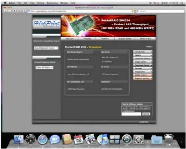
Driver updates are posted on the card's product page, under the "Download Center" section.
The latest package is posted towards the right-hand side of the page, under “Mac Driver”. On the left-hand side of the page, there is a section devoted to user documentation. The latest versions of the Product, and Web-based RAID Management Manuals are posted here.
Mac OS X Driver and RAID Management Installation
The driver and software packages for the RocketRAID 431x/432x includes both the device driver for OS X, and a copy of the Web RAID Management utility. Copy the Mac driver and software package from the Software CD, to the Mac Desktop. Open the .dmg file, and double click "rr3xxx_4xxx" to begin installation.
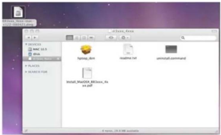
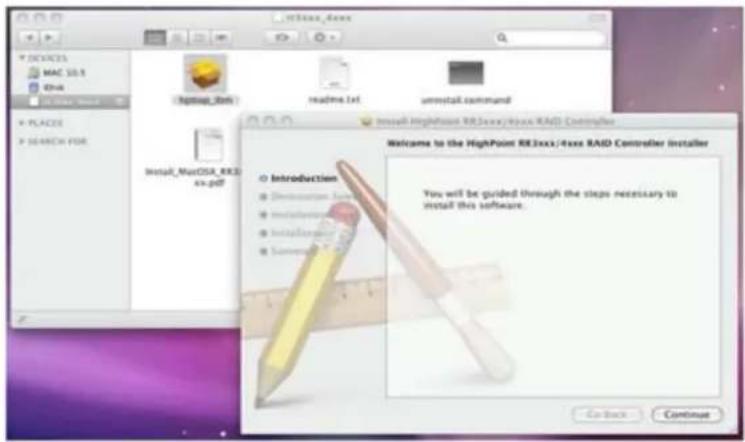
Click "Continue" to proceed with installation
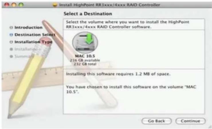
Select the installation destination:
Click "Continue"
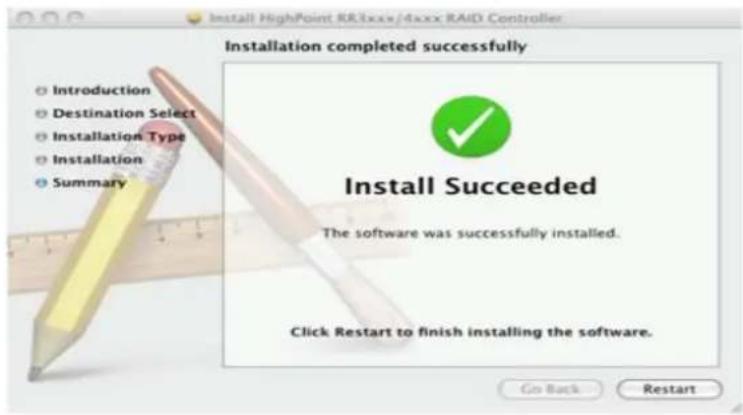
Click "Restart" – after OS X reboots, the card will be recognized by the system. Configure arrays using the Web RAID Management interface. User guides for the Web interface are available from http://www.hptmac.com. Check the product page for the RocketRAID 431x/432x, and click on the "Download Center" link.
If the users have more requirements to boot from the Host Adapter, please performing below step.
Configure the cards to support booting OS X, fo Mac Pro systems Updating the Rocket RAID Firmware – EFI
For RocketRAID 35xx and 4xxx host adapters
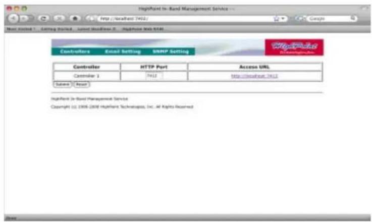
1) Log into RAID Management Utility (Web GUI). Open a web browser (such as Safari or Firefox) and enter the following URL: http://localhost:7402
2) Once connected click on the Access URL – this will open the log in screen.
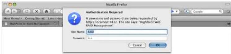
3) Type in the User name and Password, then click "OK". The default Username is RAID, while the default Password is hpt.
4) After successfully logging in, the Web GUI will display the Manage-Array screen. Select Manage-Device from the menu, and scroll to the bottom of this page and locate the Update Firmware function.
5) Click on the Browse button, and browse to the location of the EFI firmware update. The EFI firmware is the second file included with Driver and Firmware download (see step 3).
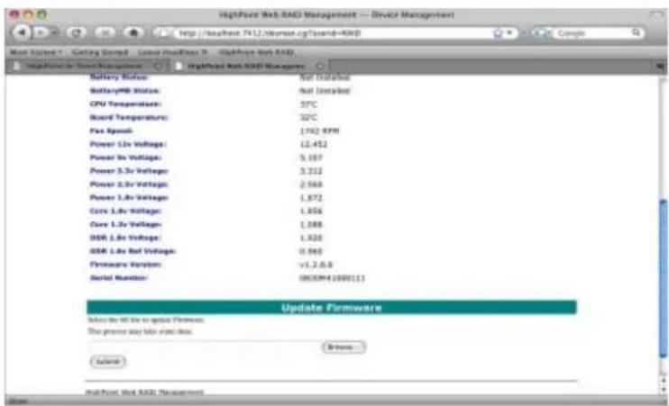
6) Select the firmware update (.blf file) and click the Submit button. The interface will notify you when the update is complete. Exit the Web GUI and reboot OS X.
Cloning the boot volume to a RAID Array
1) After flashing the EFI firmware update, download Carbon Copy Cloner. Carbon Copy Cloner is a free disk imaging utility that can be used to duplicate the system's current boot volume, to a disk or RAID array attached to the RocketRAID card. http://www.bombich.com/software/ccc.html
2) Clone OS disk to disk on RAID array
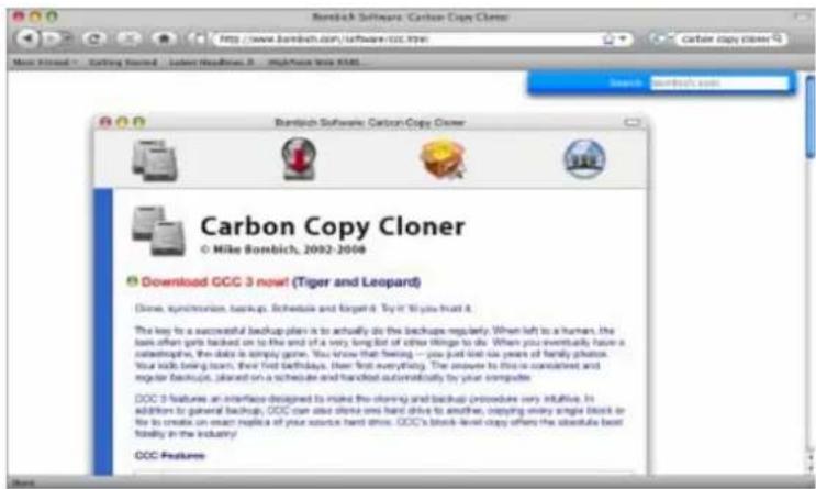
3) Start Carbon Copy Cloner. For the Source disk, select the current Mac OS X boot drive. For the Target disk, select a disk or array attached to the RocketRAID host adapter.
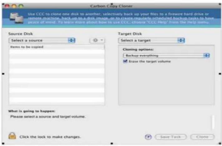
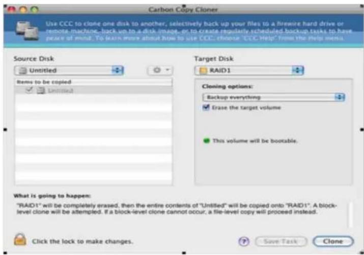
4) Once the Source and Target disks have been selected, click Clone to start the duplication process. The utility will display a progress bar and notify you when the copy procedure is complete.
![Disk-to-disk clone [File-level] Closing /Applications/OVD Player.app/Contents/Resources/R Iraq/Localizable Millings Untitled RAID1 Data copied: 156.52 MB Time elapsed: 00:00:21 Stop Get a SuperDrive from OWC that burns faster. www.macnates.com What is going to happen: "RAID1" will be completely erased, then the entire contents of "Untitled" will be copied onto "RAID1". A block-level clone will be attempted. If a block-level clone cannot occur, a file-level copy will proceed instead. Click the lock to prevent further changes. Save Task Clone](/content/2026/06/1184683/images/0a0d53d58122901c5506861a2916fd2f88e28aba7a842906593b32f50dab7fb8.jpg)
Change the boot volume
1) After cloning the boot volume, open the System Preferences window and select "Startup Disk".
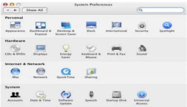
2) Set the RAID array or disk attached to the RocketRAID card as the startup disk, and click "Restart".
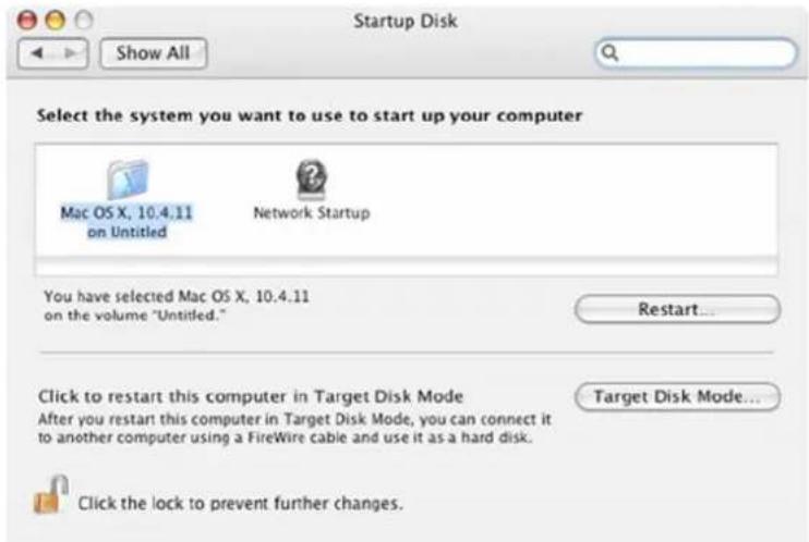
3) You can also select the boot volume using the Alt key, after powering up the Mac system. This command will display available boot volumes.
Customer Support
If you encounter any problems while utilizing the RocketRAID host adapter, or have any questions about this or any other HighPoint product, feel free to contact our Customer Support Department.
Troubleshooting Checklist
Before contacting our Customer Support department:
- Make sure the latest BIOS, driver and HighPoint RAID Management software has been installed for the host adapter. The latest updates are available from our website.
- Prepare a list of the computer system's hardware and software (motherboard, CPU, memory, other PCI-E devices/host adapters, operating system, applications)
Contact Information
E-mail address: support@highpoint-tech.com
Phone: 408-240-6119
9:00AM-5:00PM, Pacific Standard Time
Contact Us
HighPoint Corporate Headquarter USA
Address 1161 Cadillac Ct.
Milpitas, CA, 95035
Website: http://www.highpoint-tech.com
Phone: 1-408-942-5800 (9 am \~ 6 pm PST, M-F) Fax: 1-408-942-5801
E-mail: sales@highpoint-tech.com
Support: support@highpoint-tech.com
Support Phone: 1-408-240-6108 (9 am \~ 5 pm PST, M-F)
HighPoint Taiwan
5F., No.3, Swei Lane, Jhongjheng Rd.
Sindian City, Taipei County 231, Taiwan (R.O.C.)
Website: http://www.highpoint-tech.com/Taiwan/indextw.htm
Phone: +886-2-2218-3435 (9 am \~ 6 pm)
Fax:+886-2-2218-3436
E-mail:sales@highpoint-tech.com
Support: support@highpoint-tech.com
HighPoint China
4th Floor Kehaifulin Building, N0. 12
Zhong Guan Cun South Rd.
Haidian District Beijing, China 100081
Website: http://www.highpoint-tech.cn/
Phone: +86-10-6213-0920 (9 am \~ 6 pm)
Fax:+86-10-6897-5074
E-mail: sales@microaurora.com.cn
Support: support@microaurora.com.cn
FCC Part 15 Class B Radio Frequency Interference statement
This equipment has been tested and found to comply with the limits for a Class B digital device, pursuant to part 15 of the FCC Rules. These limits are designed to provide reasonable protection against harmful interference in a residential installation. This equipment generates, uses and can radiate radio frequency energy and, if not installed and used in accordance with the instructions, may cause harmful interference to radio communications. However, there is no guarantee that interference will not occur in a particular installation. If this equipment does cause harmful interference to radio or television reception, which can be determined by turning the equipment off and on, the user is encouraged to try to correct the interference by one or more of the following measures:
●Reorient or relocate the receiving antenna.
- Increase the separation between the equipment and receiver.
- Connect the equipment into an outlet on a circuit different from that to which the receiver is connected.
- Consult the dealer or an experienced radio/TV technician for help.
Modifications not expressly approved by the manufacturer could void the user's authority to operate the equipment under FCC rules.
This device complies with part 15 of the FCC Rules. Operation is subject to the following two conditions: (1) this device may not cause harmful interference, and (2) this device must accept any interference received, including interference that may cause undesired operation.
European Union Compliance Statement
This Information Technologies Equipment has been tested and found to comply with the following European directives:
●European Standard EN55022 (1998) Class B
●European Standard EN55024 (1998)
Thank You
Thank you for purchasing the RocketRAID 431x/432x SAS/SATAII RAID Host adapter. We appreciate your support, and welcome any questions, comments or product suggestions you may have.
- Trademarks
- Notice
- Table of Contents
- HIGHPOINT TECHNOLOGIES, INC....5
- CONGRATULATIONS
- HARDWARE -- DESCRIPTION AND INSTALLATION
- ROCKETRAID BIOS UTILITY
- HIGHPOINT RAID MANAGEMENT AND DEVICE DRIVER CD
- CUSTOMER SUPPORT
- HighPoint Technologies, Inc.
- - Specifications and Features
- Host Adapter Architecture
- Advanced RAID Features
- Array Monitors, Alerts and Indicators
- HighPoint RAID Management (HRM)
- Operating System Support
- Physical Specifications
- Thermal and Atmospheric Characteristics:
- Electrical Characteristics:
- - Kit Contents
- Hardware - Description and Installation
- 1-RocketRAIDAdapter layout
- - RocketRAID 431x/4321 Adapter layout
- A1,F1
- J1
- J2
- J3 (BBU connector)
- BEEP1-Speaker
- J4 - Ethernet Port (RocketRAID 4321)
- Cable – Internal Mini-SAS to Mini-SAS
- - RocketRAID 4320 Adapter layout
- J16
- J14 (BBU connector)
- EthernetPort
- - RocketRAID 4322 Adapter layout
- Port1, Port2
- J3 (Battery connector)
- J4 (HighPoint Ethernet Board connector)
- – Installing the RocketRAID Host Adapter
- - Installing the RocketRAID 431x/4320/4321 Host Adapter
- - Installing the RocketRAID 4322 Host Adapter
- - Verifying Installation
- - Battery Backup
- - BIOS Settings Overview
- Using the BIOS Utility
- BIOS Menu Shortcuts
- Logging In
- BIOS Commands
- System
- Disk
- Array
- Controller
- Window
- Help
- - Creating RAID Arrays
- Initializing Disks:
- Creating Arrays:
- - Deleting Arrays
- - Monitoring the Host Adapter, Arrays and Devices
- Disk/Array Status
- Controller Information
- Event Log
- - Maintaining Arrays
- Network Settings
- Controller Settings
- Device Settings
- Spare Disks
- Verifying Arrays
- - Additional Functions and Settings
- Set Boot
- Hot-Swap
- Adding/removing Disks
- Adding/removingArrays
- Window Menu
- - Creating a driver diskette
- To create a driver floppy diskette:
- - Device Driver Installation
- Windows Driver Installation (Win2000, XP, Win 2003)
- Installing the RocketRAID 431x/432x driver for an existing Windows system.
- Installation Verification
- Installing the RocketRAID driver during a fresh Windows installation
- Windows Vista/2008 Driver Installation
- Installing the driver during a fresh Windows Vista/2008 installation
- Installing the driver for an existing Windows Vista/2008 system
- Linux and FreeBSD Device Driver installation
- - HighPoint RAID Management Utilities (HRM)
- Windows Operating Systems – Installing the Web-based Management Utility
- Red Hat Enterprise/CentOS, Fedora Core, Open SuSE – Installing the Web-based Management utility
- rpm -i hptsvr-https-1.4-8.i386.rpm (or hptsvr-https-1.4-8.x86_64.rpm)
- Debian/Ubuntu Linux Distributions – Installing the Web-based Management Utility
- The following files will be installed/configured:
- Uninstalling the Utility
- Linux Distributions - Command Line Interface (CLI)
- Mac OS X Driver and Web-based RAID Management Utility
- Mac OS X Driver and RAID Management Installation
- Configure the cards to support booting OS X, fo Mac Pro systems Updating the Rocket RAID Firmware – EFI
- Cloning the boot volume to a RAID Array
- Change the boot volume
- Troubleshooting Checklist
- Contact Information
- Contact Us
- HighPoint Corporate Headquarter USA
- HighPoint Taiwan
- HighPoint China
- FCC Part 15 Class B Radio Frequency Interference statement
- European Union Compliance Statement
- Thank You
Brand : Highpoint
Model : RocketRAID 4311
Category : NAS