KM0104 - Receiver Krüger&Matz - Free user manual and instructions
Find the device manual for free KM0104 Krüger&Matz in PDF.

User questions about KM0104 Krüger&Matz
0 question about this device. Answer the ones you know or ask your own.
Ask a new question about this device
Download the instructions for your Receiver in PDF format for free! Find your manual KM0104 - Krüger&Matz and take your electronic device back in hand. On this page are published all the documents necessary for the use of your device. KM0104 by Krüger&Matz.
USER MANUAL KM0104 Krüger&Matz
text_image
Technical diagram illustrating three-step mechanical assembly steps: pinning, locking mechanism, and cutting tool.Fig.3
text_image
Technical diagram showing exploded view of a device with labeled components and a close-up of its internal structure.EINFÜGEN VON SD
text_image
Diagram showing a device with a labeled control panel and directional arrow pointing to the interior panel.ANSCHLUSSDIAGRAMM
text_image
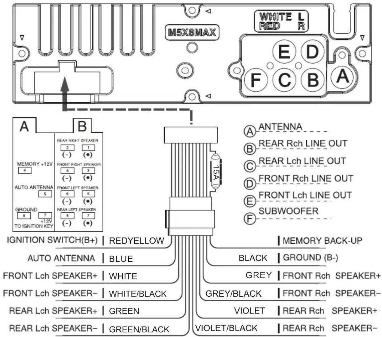
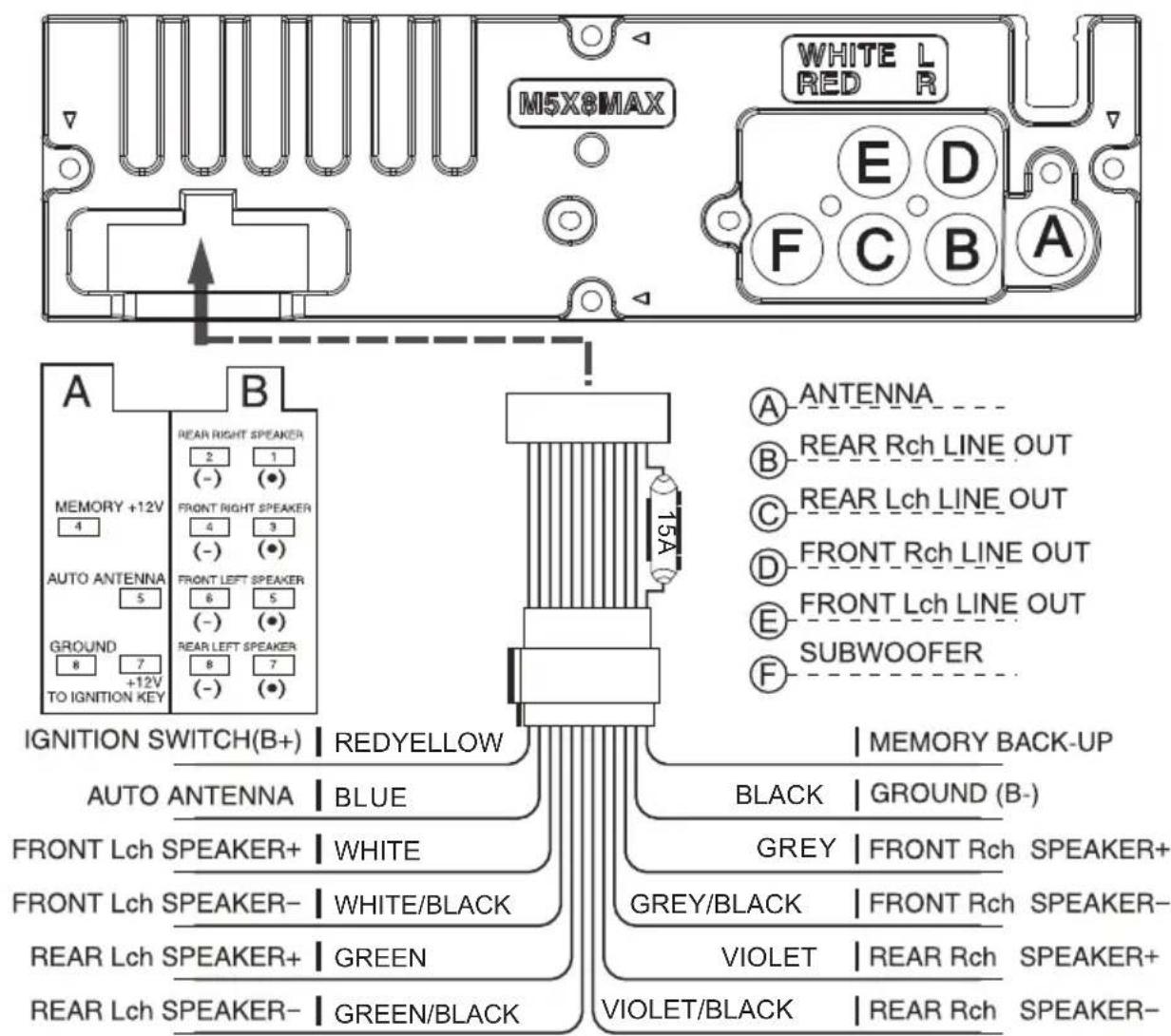
M5X8MAX WHITE L RED R E D F C B A A B MEMORY +12V 4 AUTO ANTENNA 5 GROUND 8 7 +12V TO IGNITION KEY REAR RIGHT SPEAKER 2 1 (-) (●) FRONT RIGHT SPEAKER 4 3 (-) (●) FRONT LEFT SPEAKER 6 5 (-) (●) REAR LEFT SPEAKER 8 7 (-) (●) 15A A ANTENNA B REAR Rch LINE OUT C REAR Lch LINE OUT D FRONT Rch LINE OUT E FRONT Lch LINE OUT F SUBWOOFER IGNITION SWITCH(B+) | REDYELLOW AUTO ANTENNA | BLUE FRONT Lch SPEAKER+ | WHITE FRONT Lch SPEAKER- | WHITE/BLACK REAR Lch SPEAKER+ | GREEN REAR Lch SPEAKER- | GREEN/BLACK MEMORY BACK-UP BLACK | GROUND (B-) GREY | FRONT Rch SPEAKER+ GREY/BLACK | FRONT Rch SPEAKER- VIOLET | REAR Rch SPEAKER+ VIOLET/BLACK | REAR Rch SPEAKER-A) ANTENNE
B) LINIENAUSGANG HINTEN RECHTS
C) LINIENAUSGANG HINTEN LINKS
D) LINIENAUSGANG VORNE RECHTS
text_image
Technical diagram of a remote control device with numbered labels pointing to various function keys and buttons.Deutsch
VERKEHRSINFORMATIONEN (TA)
natural_image
Isometric line drawing of a rectangular electronic component with a small curved cutout and directional arrows indicating flow or movement (no text or symbols)natural_image
Simple line drawing of a rectangular object with a small inset showing a positive charge (no text or symbols)natural_image
Line drawing of a rectangular electronic component with a clip inserted, no text or symbols presentTECHNISCHE DATEN
Wire connection diagram 16
Front panel layout 17
General operations 18
RDS Operations 19
Remote control layout 20
Replacing the battery 21
Specification 22
PRECAUTIONS
Choose the mounting location where the unit will not interfere with the normal driving function of the driver.
Before finally installing the unit, connect the wiring temporarily and make sure it is all connected up properly and the unit and the system work properly.
Use only the parts included with the unit to ensure proper installation. The use of unauthorized parts can cause malfunctions.
Consult with your nearest dealer if installation requires the drilling of holes or other modifications of the vehicle.
Install the unit where it does not get in the driver's way and cannot injure the passenger if there is a sudden stop. Like an emergency stop.
Avoid installing the unit where it would be subject to high temperature, such as from direct sunlight, or from hot air, form the heater, or where it would be subject to dust, dirt or excessive vibration. Do not expose this equipment to rain or moisture.
DIN FRONT-MOUNT (Method A)
Installing the unit
-
Dashboard
-
Holder
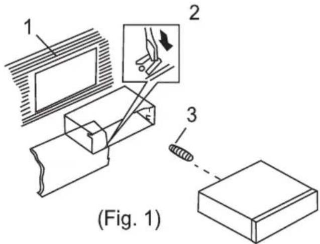
After inserting the holder into the dashboard, select the appropriate tab according to the thickness of the dashboard material and bend them inwards lo secure the holder in (Fig. 1) place.
- Screw
text_image
1 2 3 (Fig. 1)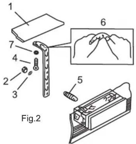
text_image
1 2 3 4 5 6 Fig.2- Dashboard
- Nut(5 mm)
- Spring Washer
- Screw (5x25rnm)
- Screw
- Strap
Be sure to use the strap to secure the back of the unit in place.
The strap can be bent by hand to the desired angle. - Plain Washer
text_image
Technical diagram illustrating three-step mechanical assembly steps: pinning, cutting, and cutting through a key.Fig.3
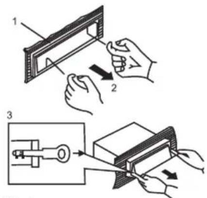
- Frame
- Insert fingers into the groove in the front of frame and pull out to remove the frame. (When reattaching the frame, point the side with a groove downwards and attach it.)
- Lever
Insert the levers supplied with the unit into the grooves at both sides of the unit and shown in figure until they click. Pulling the levers makes possible to remove the unit from the dashboard.
DIN REAR-MOUNT (Method B)
Installation using the screw holes on the sides of the unit
Fastening the unit to the factory radio mounting bracket:
- Select a position where the screw holes oft he bracket and the screw holes of the main unit become aligned (are fitted), and tighten the screws at 2 places on each side. Use either truss screws (5 x 5mm) or flush surface screws (4 x 5mm)
- Screw
- Dashboard or Console
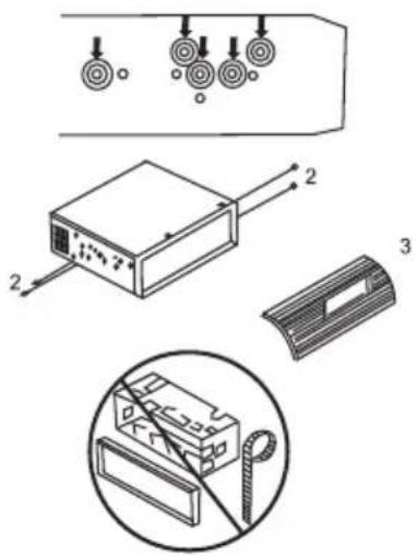
text_image
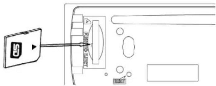
Technical diagram showing exploded view of a device with labeled components and a close-up of its internal structure.INPUT THE SD CARD
The SD oblique angle keeps Rightward exposure, put into the SD slot and press it again to eject.
text_image
Diagram showing a device with an S button connected to a panel, labeled with Chinese text and symbols.WIRE CONNECTION DIAGRAM
text_image
M5X8MAX WHITE L RED R E D F C B A A B MEMORY +12V 2 1 (-) (●) AUTO ANTENNA 4 FRONT RIGHT SPEAKER 4 3 (-) (●) GROUND 6 FRONT LEFT SPEAKER 6 5 (-) (●) TO IGNITION KEY 8 REAR LEFT SPEAKER 8 7 - (-) (●) IGNITION SWITCH(B+) REDYELLOW 15A MEMORY BACK-UP AUTO ANTENNA BLUE BLACK GROUND (B-) FRONT Lch SPEAKER+ WHITE GREY FRONT Rch SPEAKER+ FRONT Lch SPEAKER- WHITE/BLACK GREY/BLACK FRONT Rch SPEAKER- REAR Lch SPEAKER+ GREEN VIOLET REAR Rch SPEAKER+ REAR Lch SPEAKER- GREEN/BLACK VIOLET/BLACK REAR Rch SPEAKER-FRONT PANEL LAYOUT
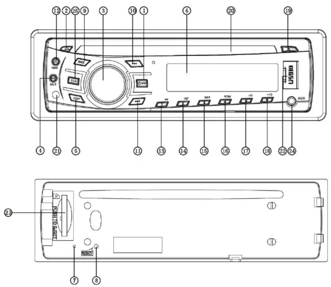
- Power / Mode Button
- Release Button
- Volume / Sel Button
- Mute Button
- Display Button
- LCD Display
- Flashing LED
- Reset Button
- Band switch / ID3 select
- Tune Seek & Track forward Button
- Tune Seek & Track reverse Button
- Automatically memory storing
-
Play/Pause & Preset Button 1
-
Intro & Preset Button 2
- Repeat & Preset Button 3
- Random & Preset Button 4
- Preset Button 5
- Preset Button 6
- Eject knob
- CD slot
- Remote Control Sensor
- USB connecter
- SD/MMC Slot
- AUX IN JACK
- SCN button
GENERAL OPERATIONS
FRONT PANEL RELEASE
Press REL button (2) to detach the removable front panel.
SOUND ADJUSTMENT
Turn on (3) can adjust the desired volume quality.
Press SEL button (3) will change in the following order.
Option:

flowchart
graph LR
    A["VOL (Volume)"] --> B["BAS (Bass)"]
    B --> C["TRE (Treble)"]
    C --> D["BAL (Balance)"]
    D --> E["FAD (Fader)"]
VOLUME
Rotating this knob, you can adjust VOL/BASS/TREB/BAL/FAD. To select the functions, press the VOL knob shortly until the desired functions are shown on the display.
Increase or decrease the volume by turn the VOL knob right or left. These buttons can be used to adjust the BASS, TREBLE, BALANCE and FADER.
BASS
Press VOL/SEL button (3) one time. Adjust bass level by using VOL/SEL (3) knob.
TREBLE
Press VOL/SEL button (3) two times. Adjust treble level by using VOL/SEL(3) knob
BALANCE
Press VOL/SEL button (3) three times. Adjust sound balance between left and right speakers by using VOL/SEL (3) knob.
FADER (optional)
Press SEL button (3) four times. Adjust sound balance between front and rear speakers by using VOL/SEL (3) knob.
SELECT MENU
Press VOL/SEL button for several seconds, selecting menu is activated as cyclical mode of following function for use's selection:

flowchart
graph LR
    A["TIME DISPLAY"] --> B["DSP OFF ON"]
    B --> C["LOUD OFF/ON"]
    C --> D["DEMO OFF/ON"]
    D --> E["AEM OFF/ON"]
    E --> F["BEEP ON/OFF"]
    F --> G["SEEK ½"]
    G --> H["STEREP/MONO"]
    H --> I["DX/LOCAL"]
    I --> J["VOL LAST/ADJ"]
    J --> K["AREAUR/USA"]
    K --> A
CUSTOMIZE RGB COLOR ILLUMINATION
The illumination color keep changing when unit power on. Long press DISP key, rotate Volume to select Auto OFF, short press DISP to select illumination color.
\~ Setting RDS Mode Press AF button (20) and release immediately to switch on or off RDS mode. Whenever RDS is switched on, symbol "AF" appears on the display.
AF / REG
AF
- AF I REG key directs the activation of AF SEARCH.
- AF indicator is displayed when AF is ON, AF search is activated when reception is bad.
- During FM MODE, when AF is ON, SEEK, SCAN, AUTO, MEMORY function can only receive and save RDS program. However, when Italy option is in use, regardless of RDS programs that satisfy SD LEVEL Can be received and saved.
| Indicator Condition | |
| AF ON AF ON MODE, RDS information is received. | |
| AF OFF AF OFF MODE | |
| AF blink AF ON MODE, RDS information is not received. | |
REGION
- AF MODE is converted to REGION ON / OFF MODE when SEL is pressed for longer 3 sec.
- ON : PI CODE is checked when AF CHECK in progress.
- OFF: PI CODE and COVERAGE AREA is not checked when AF CHECK in progress.
PTY
RADIO MODE
- Press SEL key, PTY flashing on display when select PTY. If there are no keys entered for 2 seconds, previously selected PTY is searched. During 1 LOOP, if desired PTY is not found, NO PTY is displayed.
- 2 program types are SPEECH and MUSIC.
By pressing PTY once, MUSIC is entered. When PTY is pressed the second time, SPEECH is entered.
M1\~M6 keys can be used to select the desired program type.
TA
TA button is operated as follows:
- Press SEL enter TA, TA is turned ON / OFF and TA indicator is displayed. When traffic announcement is transmitted, regardless of the mode, traffic announcement is received.
If VOLUME LEVEL is below 20, VOLUME LEVEL is raised to 20, and returns to its previous mode and volume level when the traffic announcement is over.
If volume is adjusted during traffic announcement, only the previous volume is valid.
- When TA is on, SEEK, SCAN, AUTO MEMORY function can be received or saved only when traffic program identification code has been received.
- When TA is ON, traffic program identification code is not received during specified time.
TA ALARM : NO TA/ TP is displayed and alarm is set off.
TA SEEK : TA SEEK is activated.
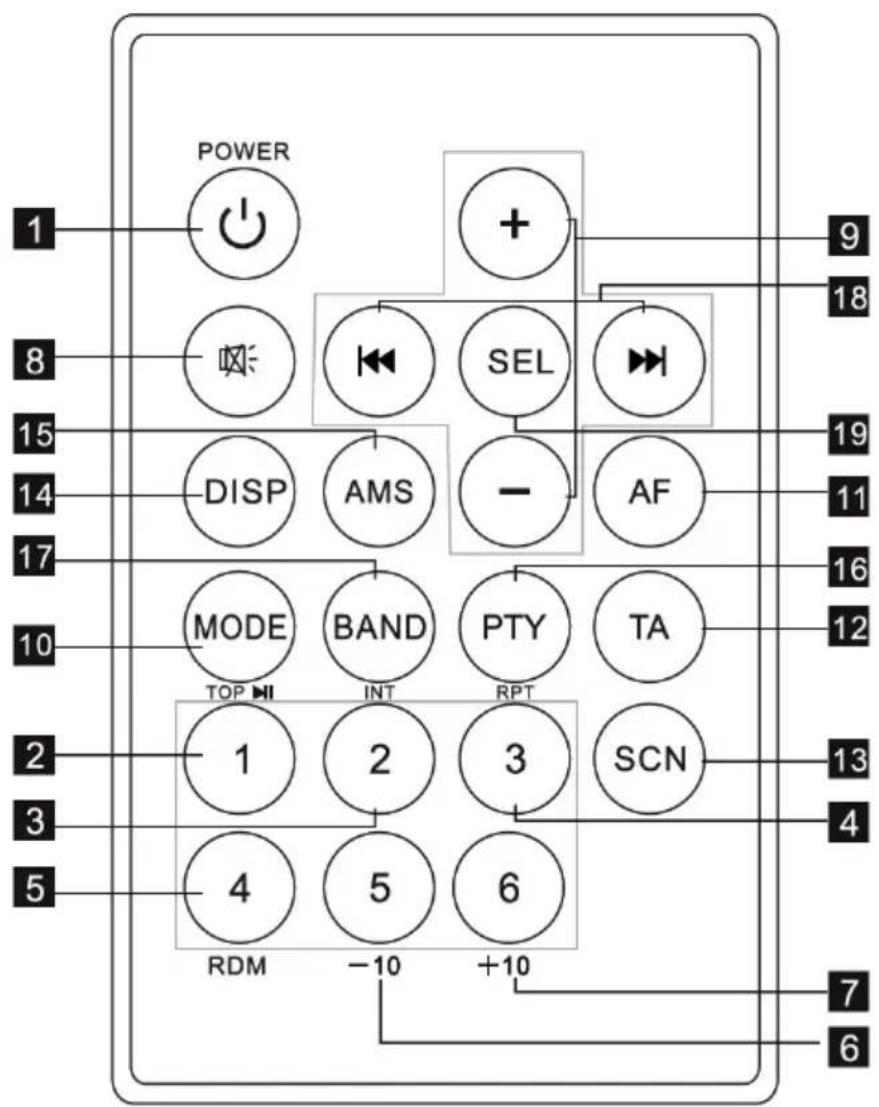
REMOTE CONTROL LAYOUT
flowchart
graph TD
    A["POWER"] --> B["+"]
    C["MODE"] --> D["AMS"]
    E["BIAND"] --> F["INT"]
    G["PTY"] --> H["RPT"]
    I["TA"] --> J["SCN"]
    K["DISP"] --> L["AMS"]
    M["AF"] --> N["AF"]
    O["SEL"] --> P["+"]
    Q["OPEN"] --> R["OPEN"]
    S["Power Input 1"] --> T["Power Supply"]
    U["Power Input 8"] --> V["Power Supply"]
    W["Power Input 15"] --> X["Power Supply"]
    Y["Power Input 14"] --> Z["Power Supply"]
    AA["Power Input 17"] --> AB["Power Supply"]
    AC["Power Input 10"] --> AD["Power Supply"]
    AE["Power Input 2"] --> AF["Power Supply"]
    AG["Power Input 3"] --> AH["Power Supply"]
    AI["Power Input 5"] --> AJ["Power Supply"]
    AK["RDM"] --> AL["-10"]
    AM["+10"] --> AN["+10"]
    AO["OPEN"] --> AP["OPEN Output 9"]
    AQ["OPEN Output 18"] --> AR["OPEN Output 18"]
- PowerButton
- Pause / Play / Preset Button1
- Intro / Preset Button2
- Repeat Playing / Preset Button3
- Random / Preset Button4
- Preset Button5
- Preset Button6
- Mute
-
Volume Control
-
Mode Switch
- Alternative Frequencies Button
- TrafficAnnouncement Button
- Scan Button
- Display Button
- APS / AMS Button
- Programe Type Button
- Band Switch
- Tuning / Selecting Tracks / F F / F R
- Select Button
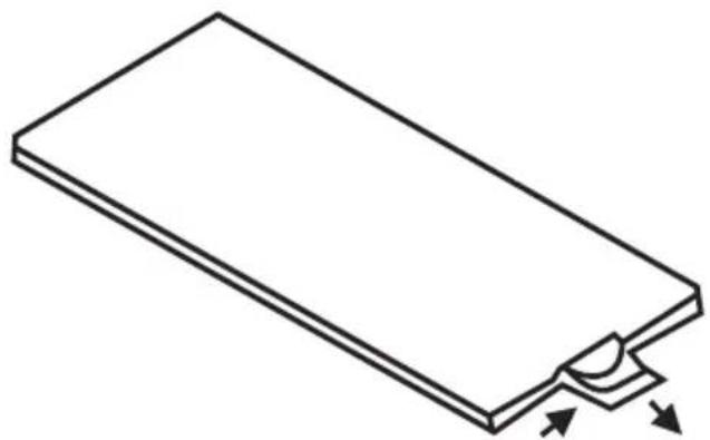
REPLACING THE BATTERY
When the operational range of the remote control becomes short or non functions while operating Replace a new CR2025 battery Make sure the battery polarity before replacement
- Pull out Battery Holder while pressing the stopper
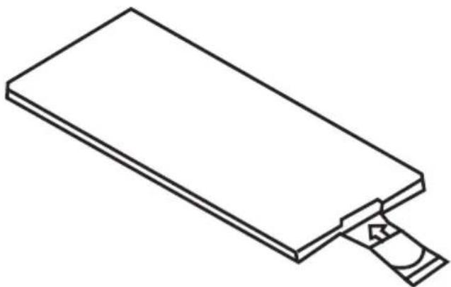
natural_image
Isometric line drawing of a rectangular electronic component with a small semicircular cutout and directional arrows indicating force or movement (no text or symbols)- Put the button type battery(+) mark upward into the Battery Holder

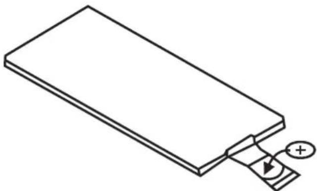
natural_image
Simple line drawing of a rectangular object with a small inset showing a plus sign and curved lines, no text or symbols present.- Insert the Battery Holder into the Remote control
natural_image
Isometric line drawing of a rectangular electronic component with a clip attached (no text or symbols)SPECIFICATION
General
| Power Supply Requirements: | DC 14,4V, Negative Ground |
| Load Impedance | 4 ohms |
| Maximum Output Power: | 40W X 4(CH) |
| Chassis Dimensions: | 178x163x50mm(WxDxH) |
| Current Drain: | 15A |
Tone Controls
| Bass (at 100Hz): | +10dB/-10dB |
| Treble (at 10K): | +10dB/-10dB |
USB/SD MUSIC Player
| Signal to Noise Ratio: | More than 60dB |
| Channel Separation: | More than 60dB |
| Frequency Response: | 20Hz-20KHz |
FM Radio
| Frequency Coverage (MHz): | 87.5 -108MHz |
| IF: | 10.7MHz |
| Sensitivity (S/N-30dB): | 12dBu |
| Stereo Separation: | >30dB |
AM Radio
| Frequency Coverage (KHz): | 522 -1620KHz |
| IF: | 450KHz |
| Sensitivity (S/N-20dB): | <42dBu |
Specifications subject to change without notice.
„The Lechpol company declares that product KM0104 is consistent with the essential requirements and other relevant provisions of directive 1999/5/EC. The proper declaration for download from www.lechpol.eu”
English

Correct Disposal of This Product (Waste Electrical & Electronic Equipment)


(Applicable in the European Union and other European countries with separate collection systems)
This marking shown on the product or Its literature, indicates that It should not be disposed with other household wastes at the end of its working life. To prevent possible harm to the environment or human health from uncontrolled waste disposal, please separate this from other types of wastes and recycle it responsibly to promote the sustainable reuse of material resources.
Household users should contact either the retailer where they purchased this product, or their local government office, for details of where and how they can take this item for environmentally safe recycling. Business users should contact their supplier and check the terms and conditions of the purchase contract. This product should not be mixed with other commercial wastes for disposal
Made in China for LECHPOL Zbigniew Leszek, Miętne, 1 Garwolińska Street 08-400 Garwolin.
SPIS TREŚCI
Instalacja 24
INSTALACJA (Metoda A)
text_image
Diagram illustrating three-step steps of a mechanical or electrical device operation, showing hand positioning and tool path.Rys.3
text_image
Technical diagram showing exploded view of a device with labeled components and a close-up of internal components including a tool and plate.INSTALACJA KARTY SD
text_image
Y P RIGHT TO UNIT LEFTnatural_image
Isometric line drawing of a rectangular electronic component with a small semicircular cutout and directional arrows indicating flow or movement (no text or symbols)natural_image
Simple line drawing of a rectangular object with a small inset showing a positive charge symbol (no text or labels)natural_image
Isometric line drawing of a rectangular electronic component with a clip inserted (no text or symbols)SPECYFIKACJA
Ogólna
text_image
Technical diagram showing three-step installation of a mechanical component with labeled parts and directional arrowsFig.3
text_image
Technical diagram showing labeled components of an electronic device with circuit board, connectors, and wiring detailsINTRODUCEREA CARDULUI SD
natural_image
Isometric line drawing of a rectangular electronic component with a small notch and two arrows indicating force or movement (no text or symbols)- Puneti bateria ou semnul (+) in sus in suport
natural_image
Simple line drawing of a rectangular object with a small circular mark and plus sign, no text or symbols present.natural_image
Line drawing of a rectangular electronic component with a clip attached (no text or symbols)SPECIFICATII
SPECIFICATII GENERALE
| ALIMENTAREA LA RETEA: | DC 14,4V, Minusul la masa |
| IMPEDANTA | 4 ohms |
| PUTERE MAXIMA: | 40W x 4(CH) |
| DIMENSIUNI: | 178x163x50mm(WxDxH) |
| CURENT CONSUMAT: | 15A |
FRECVENTE
| BASS (la 100Hz): | +10dB/-10dB |
| TREBLE (la 10K): | +10dB/-10dB |
USB/SD
| RAPORT SEMNAL / ZGOMOT | >60dB |
| SEPARARE POSTURI: | >60dB |
| RASPUNS IN FRECVENTA: | 20Hz-20KHz |
RADIO FM
| Frequency Coverage (MHz): | 87 5 -108MHz |
| IF: | 10.7MHz |
| SENSIBILITATE (S/N-30dB): | 12dBu |
| SEPARARE STEREO: | >30dB |
RADIO AM
| Frequency Coverage (KHz): | 522 -1620KHz |
| IF: | 450KHz |
| SENSIBILITATE (S/N-20dB): | <42dBu |
SPECIFICATIILE SE POT SCHIMBA FARA O INSTIINTARE PREALABILA
line
| X | Y | |---|---| | 0.0 | 0.0 | | 0.1 | 0.1 | | 0.2 | 0.2 | | 0.3 | 0.3 | | 0.4 | 0.4 | | 0.5 | 0.5 | | 0.6 | 0.6 | | 0.7 | 0.7 | | 0.8 | 0.8 | | 0.9 | 0.9 | | 1.0 | 1.0 | | 1.1 | 0.9 | | 1.2 | 0.8 | | 1.3 | 0.7 | | 1.4 | 0.6 | | 1.5 | 0.5 | | 1.6 | 0.4 | | 1.7 | 0.3 | | 1.8 | 0.2 | | 1.9 | 0.1 | | 2.0 | 0.0 |To see more product visit:
http://www.krugermatz.com
Krüger&Matz is a registered trademark