006-376 - Bike Kayoba - Free user manual and instructions
Find the device manual for free 006-376 Kayoba in PDF.

| Brand | Kayoba |
| Model | 006-376 |
| Product Type | Bicycle |
| Frame Material | Steel |
| Wheel Size | 26 inches |
| Number of Gears | 7-speed |
| Brake Type | V-brakes |
| Recommended Height | 150-180 cm |
| Maximum Rider Weight | 100 kg |
| Weight | 14 kg |
| Dimensions (L x H) | 175 cm x 110 cm |
| Power Source | Human power |
| Main Functions | Transportation, recreation, exercise |
| Maintenance | Clean with damp cloth, lubricate chain regularly |
| Safety Features | Reflectors, bell |
| Spare Parts Availability | Contact Kayoba or local dealer |
| Assembly Required | Yes (partial assembly, tools included) |
| Recommended Age | 14 years and up |
| Color | Black |
Frequently Asked Questions - 006-376 Kayoba
User questions about 006-376 Kayoba
0 question about this device. Answer the ones you know or ask your own.
Ask a new question about this device
Download the instructions for your Bike in PDF format for free! Find your manual 006-376 - Kayoba and take your electronic device back in hand. On this page are published all the documents necessary for the use of your device. 006-376 by Kayoba.
USER MANUAL 006-376 Kayoba
natural_image
Black and green KAYODA bicycle with front wheel, suspension rings, and front wheel (no visible text or symbols)
SE MOUNTAINBIKE
Bruksanvisning i original
Operating instructions
(Translation of the original instructions)
Important! Read the user instructions carefully before use.
Save them for future reference.
Jula reserves the right to make changes. In the event of problems, please contact our service department. www.jula.com
Tillverkare/ Produsent/ Produenci/ Manufacturer Jula AB, Box 363, 532 24 SKARA
Distributör/ Distributør/ Dystrybutor/ Distributor
Jula Poland Sp. z o.o., ul.
natural_image
Close-up of a hand adjusting a black mechanical linkage component (no text or symbols visible)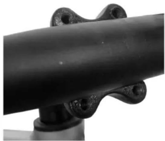
natural_image
Close-up of a black metal pipe joint with flanged ends and a cylindrical base (no text or symbols visible)4
natural_image
Close-up of a hand adjusting a black bicycle brake lever with a mesh cover (no text or symbols visible)5
natural_image
Close-up of a bicycle brake system with rotating components and a circular motion arrow (no text or symbols)6
natural_image
Pure mechanical part outline with a circular symbol containing the letter 'L' (no text or labels)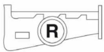
natural_image
Pure mechanical component outline with a circular symbol labeled 'R' (no text or symbols beyond the label)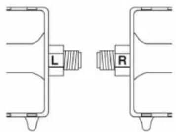
7
natural_image
Technical line drawing of a mechanical device with a cylindrical component and a small cart connected to a shaft (no text or symbols)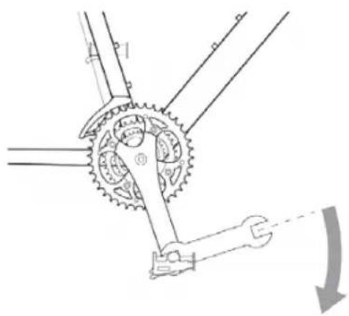
natural_image
Mechanical gear mechanism diagram showing stator and rotor assembly (no text or labels)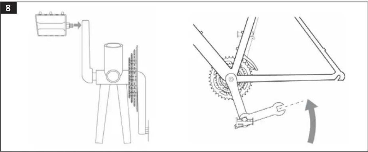
9
natural_image
Line drawing of a person riding a bicycle, no text or symbols present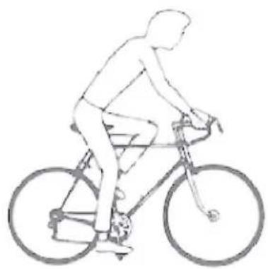
natural_image
Line drawing of a person riding a bicycle, no text or symbols present10
natural_image
Line drawing of a hand holding a small electronic device with a switch (no text or symbols)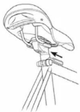
natural_image
Line drawing of a person using a tripod to adjust or install a device (no text or symbols present)↑ ↓ ↗
9
11
12
13
SÄKERHETSANVISNINGAR
VIKTIGT!
The maximum load including cyclist and baggage is 120 kg.
OWNER'S RESPONSIBILITY
The instructions describe how to ride safely and keep the bike in good condition. Read the instructions carefully, and follow them. All the important servicing and adjustments to the bike should be carried out at a bike shop. Follow these instructions if you do not have access to a bike shop or want to do the adjustments yourself.
- Familiarise yourself with the components and accessories on the bike so that you can use them properly.
- A bike is exposed to wear, like all mechanical equipment, when you use it. Different materials and components react in different ways to wear and stress. If the life span of any part of the bike (including the frame, forks and components) has been exceeded there is a risk of the part suddenly breaking, and that you lose control and fall off. Cracks, scratching or changes in colour in areas exposed to high levels of stress indicate that the component has reached the end of its useful life and should be replaced.
- It can be dangerous to use the bike for freestyle biking, stunt tricks, competitions, off-road biking etc., and you are personally responsible for any subsequent injuries or other damage resulting from the use of the bike in this way. The retailer waives all liability for any consequential damage or other loss in relation to the person who has purchased that bike or any third party.
- It is important to understand how the brakes work on the bike. If you do not use the brakes properly you could loose control of the bike and seriously injure
yourself. Different bikes can behave in different ways when you brake, so it is important to learn how the bike behaves in different situations and how hard you should press the brake levers.
ALWAYS CHECK BEFORE USE
- That the rims are in good condition and undamaged. A worn rim is a safety risk and should be replaced.
- That screw unions and components are properly tightened and not worn or damaged.
- That the seat is comfortably adjusted.
- That the brakes are working properly.
- That the steering does not jam, or has too much play.
- That the wheels are not buckled and that the wheel bearings are correctly adjusted.
- That the wheels are properly attached in the back/front forks.
- That the tyres are in good condition and have the correct tyre pressure.
- That the pedals fit properly in the crank arms.
- That the gears are correctly adjusted.
• That all the reflectors are fitted. - That all the screw unions are correctly tightened and that the wires are undamaged and correctly drawn along the frame.
- That all the nuts and bolts are properly tightened.
- That the rim/disc brake pads are not worn out.
- That the tyres are not worn or damaged.
- That the lights are working at the front and back.
- That all the reflectors are intact and clean.
• That the brakes are working properly.
ROAD SAFETY
• Always wear a bike helmet.
- Follow local traffic regulations.
- Do not put anything on the bike that can get caught up and obstruct the functions of the bike.
- Do not ride on the same side as oncoming traffic.
- Do not ride alongside another bike.
- Do not give rides on bikes not intended for this.
- Do not swing out into traffic.
- Do not hang anything from the handlebars that makes it difficult to steer, or which could fasten in the front wheel.
- Do not hang onto another vehicle.
- Do not ride too close to a vehicle in front.
• Cycling in the rain or on wet roads:
- The braking power is reduced by water and ice.
– Cycle more slowly in wet weather and brake earlier than in dry weather.
- Follow local regulations when cycling in the dark:
- The bike must have a front lamp with a white light and a back lamp with a red light, in addition to the reflectors already fitted on the bike.
- Wear bright clothes and a high-visibility jacket if possible.
- Check that the bike's reflectors are correctly positioned, properly attached, clean and not obscured. Replace damaged reflectors immediately.
- Any shock absorbers on the bike should be serviced at a bike shop. See instructions from shock absorber manufacturer.
By law a bike must always be fitted with brakes and a bell. On public roads it is important to take the following into consideration:
- As a road user you are obliged to be familiar with and to follow traffic regulations.
• We recommend that you always wear a helmet when cycling. If you are under 15 and ride a two-wheeled bike you must by law wear a bike helmet.
• Never leave a child on the bike.
SERVICE
Only use identical spare parts when replacing parts that are essential for safety. This will guarantee that the bike remains safe to use. We recommend that you have the bike serviced every six months at a bike shop (more often if you ride it a lot or put a lot of strain on it). After adjusting, check that all screw unions are correctly tightened and that the wires are undamaged and correctly drawn along the frame.
DESCRIPTION
- Saddle
- Saddle post
- Quick-release lock, saddle post
- Frame
- Stem and handlebars
- Front reflector
- Brake and gear wires
- Shock absorbing front fork
- Front wheel
- Spoke reflector
- Front disc brake
- Pedal
- Front gear
- Pedal arm
- Sprocket
EN
- Bike stand
- Chain
- Rear gear
- Back wheel
- Rear disc brake
- Back reflector
FIG. 1
ASSEMBLY
Suitable tools for assembly and adjustment.
• Combination spanners, sized 14 (2) and 15 mm
• Hex keys, size 4 and 5 mm
• Phillips screwdriver PH2
- Grease
HANDLEBARS
- Unscrew the bracket on the stem with a 5 mm hex key.
FIG. 2
- Put the handlebars on the stem. Make sure that they are properly centred and have a suitable angle for the handbrake and gear lever, and that the brake and gear wires are on the right sides of the frame and front fork. If the wires are not properly positioned the handlebars or fork has turned, and must be turned back before fitting the handlebars.
FIG. 3
- Screw together the bracket and tighten the two hex screws alternately.
FIG. 4
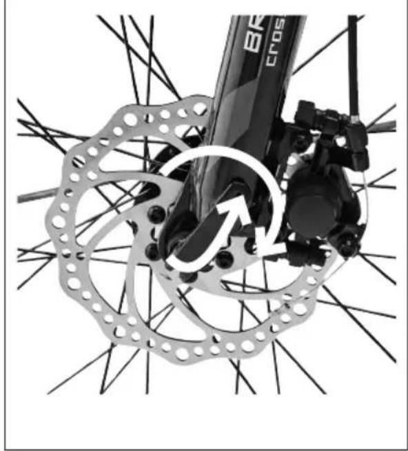
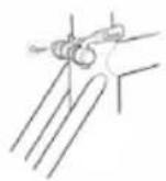
FRONT WHEEL
-
Remove transport protection on the brake calliper, in the form of a small piece of plastic that separates the brake pads.
-
Put the wheel axle in the slots on the fork legs and align the brake disc to the brake calliper. Make sure the front wheel is centred between the fork legs.
- Close the quick-release lock and firmly tighten the adjusting nut on the opposite side.
- Open the quick-release lock, tighten the adjusting nut another 3/4 turn, and then close it again. Closing the quick-release takes a little effort, so that it does not open unintentionally and loosen the wheel.
FIG. 5
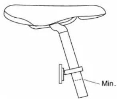
SADDLE AND SADDLE POST
Grease the saddle post and insert it into the saddle tube, and then lock to the required height with the quick-release.
IMPORTANT:
The marking for the top position on the saddle post should not be seen over the saddle tube.
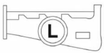
PEDALS
The pedals are different and are therefore marked with "L" (Left) and "R" (Right). If they are fitted on the wrong side or screwed in skew in the crank arms this can damage the threads. Grease the threads on the pedals before fitting.
FIG. 6
Fitting the right-hand pedal (R)
Screw in the pedal clockwise on the chain side of the crank arm and tighten with a 15 mm combination spanner.
FIG. 7
Fitting the left-hand pedal (L)
Screw in the pedal anticlockwise, on the opposite side of the chain, and tighten with a 15 mm combination spanner.
FIG. 8
USE
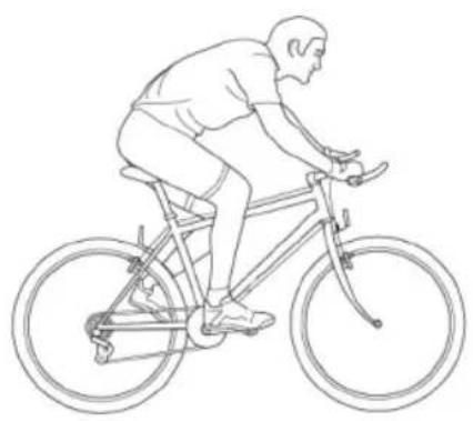
SITTING POSITION
It is important that the bike is correctly adjusted, so that it is both comfortable and safe.
FIG. 9
Adjusting the saddle
FIG. 10
Height
Open quick-release on the saddle tube, move the saddle post to the required height, and close the quick-release.
IMPORTANT:
The marking for the top position on the saddle post should not be seen over the saddle tube.
Position over the pedals
Put the sole of one foot on the pedal with the crank arms horizontal. Undo the nut holding the saddle to the saddle post. Adjust the position of the saddle forwards or backwards until the pedal is directly under the knee. Very small adjustments to the position of the saddle can affect both performance and comfort. Move the saddle a bit at a time to find the best position. The saddle can also be angled to the required position. A horizontal saddle is often recommended.
GEARS
About external gears
On gear systems with external gears the chain moves between the different sprockets on the cassette. You count the number of gears on the bike by multiplying the number of sprockets on the back wheel cassette by the number of chain rings on the chainset. You can change the gear ratio by using sprockets and chain rings with a different number of cogs. The highest gear is obtained when the chain lies on the large chain ring on the chainset and the smallest sprocket on the cassette. The lowest gear is obtained when the chain lies on the small chain ring on the chainset and the largest sprocket on the cassette. Thanks to the large number of gears you can ride in varying terrain and still pedal at about 60 rpm, which is recommended.
Changing gear
The left-hand gear shift is used to switch between the chain rings on the chainset. The right-hand gear shift is used to switch between the different sprockets on the cassette. Avoid shifting the chain to its outer position (large front chain ring and large cassette sprocket or small front chain ring and small cassette sprocket). This avoids unnecessary wear, noise and damage to the gear system.
Follow the instructions below when changing gear.
- Only change gear when the crank arms and wheels are moving forward.
- Do not force the gears.
- Do not change gear while pressing down hard on the pedals.
- Change gear in good time because you must pedal forward when changing. Change down to a lower gear before you stop. This makes it easier to start cycling
EN
again when you have a low gear. Change gear in good time when you come to a steep slope, so that you do not need to change when pressing down hard on the pedals.
- Do not pedal backwards while changing gear.
BRAKES
The bike has disc brakes and two brake handles, one for the front wheel and one for the back. They are located on the two sides of the handlebars. The right-hand brake lever controls the front brake and the left-hand brake lever controls the back brake.
WARNING!
Do not ride the bike if the brakes are not working properly.
Safe braking
Brake a bit sooner with the back brake than with the front brake and never brake with the front brake when turning or on loose or slippery surfaces.
MAINTENANCE
GENERAL
Clean the bike regularly for best lifespan and functionality. Use a mild detergent and avoid degreasing agents that can penetrate the bearings and chain and interfere with the lubrication. Store the bike in a dry place, protected from direct sunlight.
CHAIN
Lubrication
The chain should be lubricated at regular intervals. A dry chain wears more quickly, is heavy going, and can rust.
- Lubricate the chain with a suitable chain oil.
- Pedal a few turns so that the oil gets into the links.
- Wipe the chain.
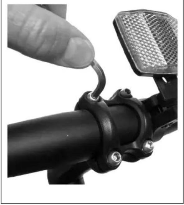
BRAKES
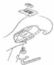
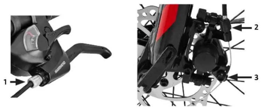
Adjusting
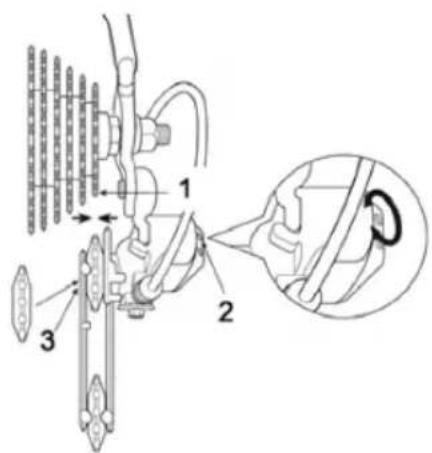
Adjust the play in the brake handle by turning the adjusting screws (1) and (2). If the brakes need larger adjustments, undo the screw (3) a little so that the wire can be moved to the required position in the fastener and then screw tight.
FIG. 11
Repairs
To replace brake pads and brake wires, contact your nearest bike shop.
GEARS
All the moving parts of the gear system must be kept clean and regularly lubricated for the gears on the bike to function properly for a long time. The derailleur should be lubricated with molybdenum grease or the equivalent.
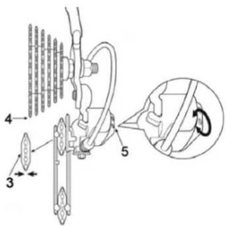
- Smallest sprocket on the cassette
- Upper adjusting screw
- Roller
- Largest sprocket on the cassette
- Lower adjusting screw
FIG. 12
Adjusting
First adjust the outer position of the chain and then the wire tension in the following steps.
Adjusting the outer position of the chain
Turn the upper adjusting screw for the gear mechanism until the roller is below the outer edge of the smallest sprocket on the cassette.
Adjusting the inner position of the chain
Turn the adjusting screw for the inner position of the chain on the back derailleur until the roller is directly under the largest sprocket on the cassette.
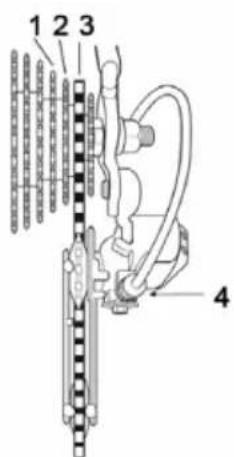
Adjusting the wire
- Third smallest sprocket on the cassette
- Next smallest sprocket on the cassette
- Smallest sprocket on the cassette
- Wire adjusting device
FIG. 13
-
Switch over the chain from the smallest sprocket on the cassette to the next smallest.
-
If the chain will not go onto the next smallest sprocket, turn the adjusting device anticlockwise to increase the tension in the wire.
-
If the chain goes past the next smallest sprocket, turn the adjusting device clockwise to reduce the tension in the wire.
-
With the chain on the next smallest sprocket, increase the wire tension while turning round the crank arms. The adjustment is complete just before the chain engages on the third smallest sprocket.
TYRES AND RIMS
- Check the tyre pressures at regular intervals. The recommended tyre pressure is given on the side of the tyre.
- Check at regular intervals that the tyres are not worn or cracked.
- Avoid contact with oil, petrol, paraffin and other agents that dissolve rubber.
• Regularly check that the spokes are correctly tensioned and that the wheels are not buckled or out of round.
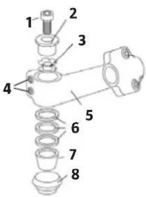
HANDLEBARS, STEM AND HEAD BEARING
- Compression screw
- Compression sleeve
- Nut with lock washers
- Stem screws
- Stem
- Spacers
- Bearing seat
- Head bearing
FIG. 14
Handlebars and stem
If the handlebars are skew and need adjusting, undo the two retaining screws on the stem (that clamp round fork tube) with a 5 mm hex key. Align the stem so that it is in line with the front wheel and retighten the retaining screws.
Head bearing
Follow these instructions to adjust any play in the head bearing.
- Undo the compression screw a little or a few turns with a 5 mm hex key.
- Undo the retaining screws on the stem with a 5 mm hex key.
EN
- Screw the compression screw clockwise until there is no longer any play, but do not tighten any more as this can damage the bearing.
- Retighten the retaining screws.
- Release the compression screw a half turn.