630-094 - Bike Kayoba - Free user manual and instructions
Find the device manual for free 630-094 Kayoba in PDF.

| Product Type | Bicycle |
| Brand | Kayoba |
| Model | 630-094 |
| Category | City/Hybrid Bike |
| Frame Material | Steel |
| Wheel Size | 28 inches |
| Brake Type | V-brakes or Caliper brakes |
| Number of Gears | 7-speed |
| Weight | Approximately 16 kg |
| Maximum Rider Weight | 100 kg |
| Recommended Age | Adults (14+) |
| Assembly Required | Yes, partial assembly required |
| Tools Included | Basic tools (wrenches, Allen keys) |
| Tire Type | Inflatable rubber tires |
| Recommended Tire Pressure | 40-65 psi |
| Seat Adjustment | Quick-release lever |
| Handlebar Adjustment | Adjustable stem |
| Lighting | Optional reflectors (battery lights not included) |
| Kickstand | Included |
| Bell | Included |
| Warranty | 2 years |
| Maintenance | Regular chain lubrication and brake adjustment |
| Spare Parts Availability | Available from Kayoba or third-party sellers |
Frequently Asked Questions - 630-094 Kayoba
User questions about 630-094 Kayoba
0 question about this device. Answer the ones you know or ask your own.
Ask a new question about this device
Download the instructions for your Bike in PDF format for free! Find your manual 630-094 - Kayoba and take your electronic device back in hand. On this page are published all the documents necessary for the use of your device. 630-094 by Kayoba.
USER MANUAL 630-094 Kayoba
natural_image
Blue and green KAYOBA bicycle with visible branding, no text or symbols on the bike itselfEN User Instructions for bike
SE - Bruksanvisning i original
EN - Operating instructions (Translation of the original instructions)
Jula reserves the right to make changes. In the event of problems, please contact our service department.
www.jula.com
Tillverkare/ Produsent / Produenci/ Manufacturer
Jula AB, Box 363, 532 24 SKARA
Importör/ Importør/ Importer/ Importer
SAFETY INFORMATION ....53
DESCRIPTION 55
ASSEMBLY....56
HANDLING 57
SÄKERHETSANVISNINGAR
A Styrlager K Pedalreflexer
B Styrstam L Vevarmar
C Styre M Kedja
D Bromsar N Hjul
1
natural_image
Technical line drawing of a mechanical device with a cart and a cylindrical component (no text or symbols)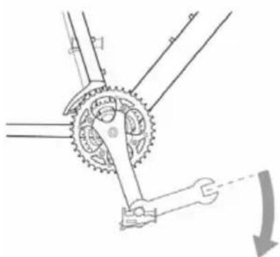
natural_image
Mechanical diagram showing a gear and wrench mechanism (no text or labels)natural_image
Technical line drawing of a mechanical device with no visible text or symbols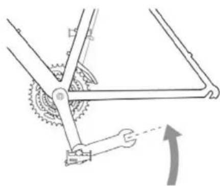
natural_image
Mechanical diagram showing a gear and linkage mechanism with no visible text or symbolsnatural_image
Line drawing of a person riding a bicycle with a wheel and bicycle (no text or symbols)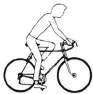
natural_image
Line drawing of a person riding a bicycle, no text or symbols present- Kassettens minsta kedjekrans
- Övre justerskruv
- Rulltrissa
- Kassettens största kedjekrans
- Undre justerskruv
- Moturs
- Medurs
A Styrelager K Pedalreflekser
B Styrestamme L Veivarmer
C Styre M Kjede
D Bremser N Hjul
natural_image
Technical line drawing of a mechanical device with a cart and a cylindrical component (no text or symbols)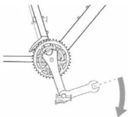
natural_image
Mechanical diagram showing a gear and wrench mechanism (no text or labels)natural_image
Technical line drawing of a mechanical device with a cylindrical component and attached components (no text or symbols)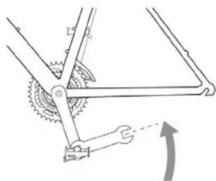
natural_image
Mechanical diagram showing a gear and wheel assembly with no visible text or symbolsnatural_image
Line drawing of a person riding a bicycle with a wheel and bicycle (no text or symbols)
natural_image
Line drawing of a person riding a bicycle, no text or symbols presentVEDLIKEHOLD AV BREMSER
Felgbrems
- Kassettens minste kjedekrans
- ∅vre justeringsskrue
- Rulletrinse
- Kassettens største kjedekrans
- Nedre justeringsskrue
-
Fornav
-
Kjegle
-
Kjegle
-
Forgaffel
-
Aksellåseskive
-
Aksel
-
Mutter
VEDLIKEHOLD AV KJEDET
Smøre kjedet
natural_image
Technical line drawing of a mechanical device with a cart and a cylindrical component (no text or symbols)
natural_image
Mechanical gear mechanism diagram showing shaft, gear teeth, and wrench (no text or labels)natural_image
Technical line drawing of a mechanical device with no visible text or symbols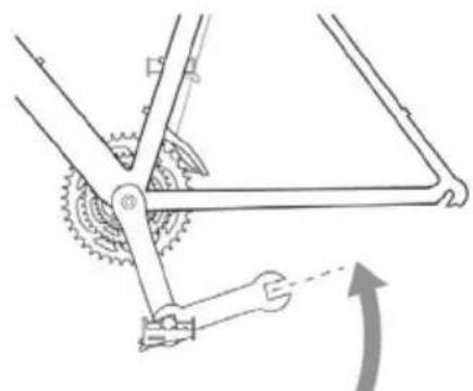
natural_image
Mechanical diagram showing a gear and wheel mechanism with no text or symbolsnatural_image
Line drawing of a person riding a bicycle with a wheel and frame (no text or symbols)
natural_image
Line drawing of a person riding a bicycle, no text or symbols presentRead the operating instructions carefully before use.
Please retain for future reference.
Maximum load including cyclist and baggage is 120 kg.
WARNING: A bike is exposed to wear, like all mechanical equipment, when you use it. Different materials and components react in different ways to wear and stress. If the lifespan of any part of the bike (including the frame, forks and components) has been exceeded there is a risk of the part suddenly breaking, and that you lose control and fall off. Cracks, scratching or changes in colour in areas exposed to high levels of stress indicate that the component has reached the end of its life and should be replaced.
Check the following items before each use
- The rims are in good condition and undamaged. A worn rim is a safety risk and should be replaced.
- Screw joints and components are tightened properly and not worn or damaged.
- The sitting position is comfortable.
- The brakes work well.
- The steering is not binding or loose.
- The wheels are not warped and the wheel bearings are correctly adjusted.
- The wheels are correctly secured to the rear/front forks.
- The tyres are in good condition and at the correct air pressure.
- The pedals are correctly secured to the crank arms.
- The gears are properly adjusted.
- All reflectors are fitted.
- Following adjustment, check that all screw joints are correctly tightened and that the cables are undamaged and correctly routed along the frame.
- We recommend that you leave your bike in at the cycle repair shop every 6 months for a service (more frequently if you cycle a lot or put a heavy load on the bike). Complete the service record after each service.
Traffic safety
• Always wear a bike helmet.
- Follow local traffic regulations.
- Do not put anything on the bike that can get caught up and obstruct the functions of the bike.
- Do not cycle on the same side as oncoming traffic.
- Do not cycle 2-deep
- Do not take anyone on the bike who is not equipped for this.
- Do not swerve out onto the road.
- Do not hang anything onto the handlebars that will make it difficult to steer or that could get caught in the front wheel.
- Do not attach yourself to another vehicle.
- Do not cycle too close to the vehicle in front.
• Cycling in the rain or on a wet roadway:
– The effects of the brakes are reduced in water and ice
– Cycle more slowly in wet weather and brake earlier than you do in dry weather.
- If you cycle in the dark, you must follow the applicable legislation:
- The bike must have a front light with a white beam and a rear light with a red beam, in addition to the reflectors already on the bike.
- Preferably wear light clothing and a reflective vest or similar.
- Check that the bike's reflectors are positioned correctly, properly secured, clean and not obscured. Replace damaged reflectors immediately.
- Any shock absorbers on the bike should be maintained by a cycle repair shop. See the shock-absorber manufacturer's user instructions.
Owner's responsibility
The user instructions describe how to cycle safely and keep the bike in good and faultless condition.
- Read and follow the user instructions carefully. All major service work or adjustments to the bike should be carried out by a bicycle mechanic. Follow these instructions if you do not have access to a bicycle mechanic and would like to carry out the adjustments yourself.
IMPORTANT! All changes are made at your own risk.
- It can be dangerous to use the bike for freestyle cycling, stunts, competitions, cycling offroad etc. and you are personally responsible for any personal injury or other damage arising as a result of you using the bike in the above manner. The retailer renounces all responsibility in respect of the person buying the bike or a third party for consequential damage or specific damage.
- Familiarise yourself with the bike's components and accessories so that you can use them in the correct manner.
DESCRIPTION
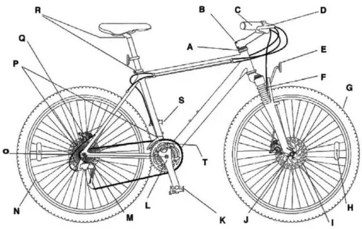
A Handlebar bearing K Pedal reflectors
B Handlebar stem L Crank arms
C Handlebars M Chain
D Brakes N Wheel
E Reflectors (front and rear) O Crank bearing
F Front fork shock absorber P Gears
G Tyre
Q Disc brake *Some models
H Reflectors
R Nuts for saddle and saddle pillar
■ Disc brakes *Some models
S Pedals
J Wheel hub
T Frame number
ASSEMBLY
Accessories
- A carrier rack and child's seat can be fitted. NOTE: Some mountain bikes require special carrier racks, check that the carrier rack is suitable for your particular bike.
• A bike trailer can be used together with the bike.
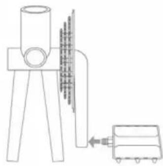
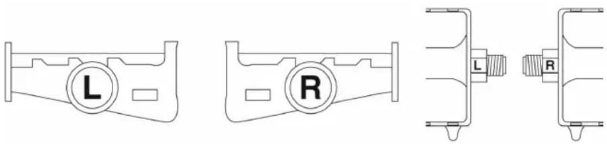
Assembling pedals
NB! The pedals are not identical – the pedal marked with an R needs to be fitted to the right crank arm and the pedal marked L to the left crank arm.
NOTE: Use a suitable lubricant on the pedal threads when fitting them.
1
natural_image
Technical line drawing of a mechanical device with a cart and fan, no text or symbols present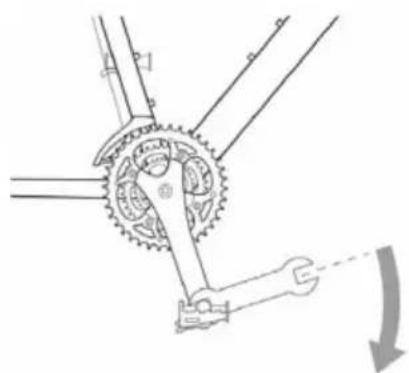
natural_image
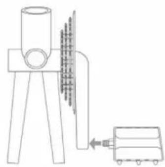
Mechanical diagram showing a gear and shaft assembly with no visible text or symbolsAssembly of right pedal (R): Screw the pedal into the crank arm on the chain side and tighten carefully with a spanner.
2
natural_image
Technical line drawing of a mechanical device with no visible text or symbols
natural_image
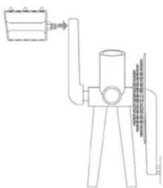
Mechanical diagram showing a gear and wheel assembly with a hand operating a tool (no text or symbols)Assembly of left pedal (L): Screw in the pedal (anticlockwise) on the opposite side to the chain and tighten carefully with a spanner.
HANDLING
Sitting position
It is very important that the bike is correctly adjusted, from the point of view of both comfort and safety. There is information on the following pages on how you adjust your sitting position to make is comfortable, safe and effective.
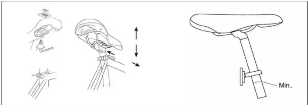
Saddle adjustment
Slacken the nut that attaches the saddle to the saddle pillar so that you can push the saddle backwards or forwards.
Adjust it to the desired position. The saddle angle can also be adjusted. We recommend that the saddle is horizontal.
Adjust the saddle height by slackening the clamp bolt attaching the saddle pillar to the seat tube. Position
the saddle pillar at the desired height and tighten the clamp bolt.
IMPORTANT!
- The saddle pillar must be lower than the maximum height indicator. The maximum height indicator must not be visible.
- Tighten the saddle pillar's clamp bolt and nut to 30 Nm using a 6 mm Allen key or a 13 mm hex key. Check that the saddle pillar is securely attached by attempting to twist the saddle by hand. You must not be able to twist the saddle.
- Never cycle if the bike or saddle pillar is not properly tightened.
Different saddle pillars are used for different types of saddle, which is why the attachments vary. Contact the retailer if you are unsure of how the saddle should be assembled.
Saddle angle
The saddle should preferably be horizontal. You can change the saddle angle, but the saddle should usually be horizontal. If you sit best with the saddle at a great angle, you should check if you can change any other setting instead.
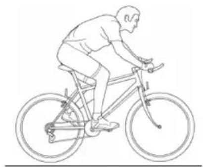
Saddle height
To check whether you have the right saddle height, you should put one of the pedals into its lowest position. Sit on the saddle wearing flat shoes and check that the heel reaches the pedal exactly when you keep your leg straight. When you cycle with the pad of your foot on the pedal, your leg should be slightly bent when the pedal is at its lowest position (see fig.).
natural_image
Line drawing of a person riding a bicycle, no text or symbols present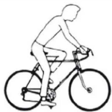
natural_image
Line drawing of a person riding a bicycle, no text or symbols presentThe position of the saddle above the pedals
Put the pad of one of your feet on the pedal with the crank arms horizontal. Adjust the position of the saddle forwards or backwards until the pedal is straight below the knee. Very small changes to the position of the saddle can affect both performance and comfort. Move the saddle a bit at a time until you find the right position.
Handlebars and handlebar stem/post
The bike may have a standard handlebar post or handlebar stem. Before use, check that all screw joints on the handlebar post/stem are properly tightened.
Standard handlebar post
Slacken tighten the expander screw on the lower part of the handlebar post until the expander wedge is loose. Carefully tap on the expander bolt if the the wedge does not loosen by itself. Once the expander wedge has loosened, move the handlebar post upwards or downwards into a position where you are sitting comfortably and can easily reach the handlebars and brake levers. The handlebars should usually be at the same height as or slightly lower than the saddle. Check that the handlebar post is in line with the front wheel.
IMPORTANT! The handlebar post has an indicator to show how far it can project from the fork. This indicator must not be visible when the handlebar post is fitted. The handlebar post must be far enough into the fork that the indicator is not visible. Once you have found the right height, position the handlebar at a right angle to the front wheel.
Tighten the expander bolt properly. It is extremely important that the expander bolt is properly tightened. Check that the handlebar post is properly secured by positioning yourself in front of the bike with your legs on either side of the front wheel. Squeeze the wheel with your legs and attempt to turn the handlebar sideways. The handlebar post must not rotate in the fork. Do not overtighten the handlebar post. There must be some give in it if the bike falls. Position the handles of the handlebars horizontally and tighten the clamp bolts properly.
NB! If the bike has gear controls fitted to the handlebar post, these can be moved up or down to the desired position. Ensure that the gear controls face upward and that the cables are not twisted. Lubricate the expander bolt every time you remove the handlebar post from the fork tube. On certain off-road bikes, the brake cable must be adjusted when the height of the handlebar post has been adjusted. Do not attempt to adjust the brake cable if the bike has low-profile brakes with a cable stop on the handlebar post.
Handlebar stem
The handlebar stem has two locking bolts at its rear end, which clamp around the fork tube. Slacken the bolts and position the handlebar stem so that it is in line with the front wheel. Then retighten the locking bolts.
IMPORTANT! Do not adjust the upper compression bolt. This is set so as to eliminate bearing play. If it is overtightened, this could result in wear.
NB! On certain off-road bikes, the brake cable must be adjusted when the height of the handlebar post has been adjusted. Do not attempt to adjust the brake cable if the bike has low-profile brakes with a cable stop on the handlebar post.
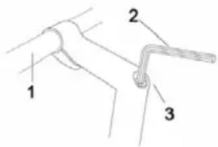 | Handlebar post with recessed bolt1. Handlebars2. Allen key, 6 mm3. Clamp bolt, Allen, handlebar post |
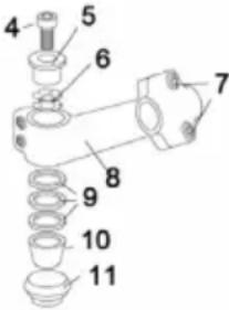 | Handlebar stem4. Compression bolt5. Compression cap6. Nut with locking washer7. Handlebar stem bolts8. Handlebar stem9. Spacers10. Bearing seat11. Handlebar bearing |
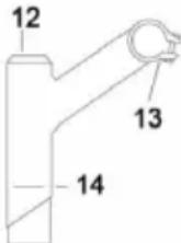 | Standard handlebar post12. Handlebar post expander13. Clamp bolt14. Handlebar maximum height indicator |
The handlebar position
Position the handlebars so that you can easily reach the gear controls and brake levers. Attempt to find a sitting position where your hands rest lightly on the handlebar. If you put too much weight on the handlebar, this leads to strain on the wrists and forearms. Do not forget to tighten all screw joints after adjustment.
NB! NEVER RAISE THE HANDLEBAR POST OR SADDLE PILLAR ABOVE THE MAXIMUM HEIGHT INDICATOR.
Adjustment of cotterless crankset
IMPORTANT! Check whether the bike's chain sprockets and crank arms are of the cotterless type. If this is the case, check that the nuts securing them to the crankset are properly tightened. We recommend that you check that the nuts are properly tightened once you have been using the bike for two weeks and then at three-monthly intervals.
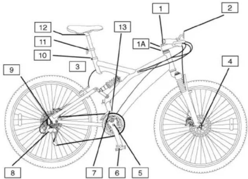
1 Expander bolt, handlebar post 20 Nm
1A Locking bolts for handlebar stem 20 Nm
2 Clamp bolt, handlebar stem 15 Nm
3 Mounting bolt for brakes (not disc brakes) 5 Nm
4 Front wheel axle nut 30 Nm
4 Front quick-release 5 Nm
5 Locking bolt for chain wheels 38 Nm
6 Pedal 40 Nm
7 Cable fixing bolt for front derailleur 4 Nm
8 Cable fixing bolt for rear derailleur 4 Nm
9 Rear wheel axle nut 30 Nm
9 Rear quick-release 5 Nm
10 Fixing bolt for saddle pillar 8 Nm
11 Fixing bolt for front and rear reflector 3 Nm
12 Saddle bolt 30 Nm
BRAKES
WARNING! It is very important that you understand how the bike's brakes work. If you use the brakes incorrectly you could lose control of the bike and seriously injure yourself. Different bikes may behave in different ways when you brake, so it is important that you learn how the bike behaves in different situation sand how hard you need to pull on the brake levers. Read the user instructions and practice cycling and braking. Contact the retailer if you require further information.
The bike has two brake levers, one for the front wheel and one for the back wheel. These are located on both sides of the handlebar. The right brake lever controls the front brake and the left brake handle controls the rear brake.
Safe braking
- Brake a bit earlier with the rear brake (right brake lever) than with the front break (left brake lever).
- Pull firmly on both brake levers. Never brake using the front brake when you are turning. It is particularly important that you bear this in mind when you are doing a tight turn or cycling on a loose surface.
IMPORTANT!
- If you brake too hard with the front break, you may brake so hard that you are thrown off the bike.
- The brakes are less effective in wet conditions. Cycle more slowly and brake earlier in wet conditions.
- Do not cycle if the brakes are not working correctly.
Check the brake adjustment and lubricate the brake springs and pivot regularly. Lubricate the exposed part of the cable to protect against corrosion. If it is difficult to brake, this is often because the cables are insufficiently lubricated. The brake cable must be disassembled for lubrication. We recommend that you have a bicycle mechanic lubricate the brake cables.
Replace the brake pads when necessary and when the wear indicator shows.
NB! In order for the brakes to be applied evenly, the wheels must not be warped, they must be correctly adjusted and the sides of the rim must be even and without any markings. The brake linings must be correctly adjusted to the sides of the rim. Contact the retailer if you are unsure about how to adjust the wheels or brakes. Protect the end of the cable with end caps so that the cable does not fray.
IMPORTANT! The brakes must not bind or remain in contact with the rim when you release the brake lever. If the brakes bind, check that the callipers, cables and brake levers are clean and lubricated. Take the bike to the retailer if the brakes bind despite these components being clean and lubricated.
EXTERNAL GEARS
Introduction
On a gear system with external gears, the chain is moved between the different sprockets on the cassette.
You can count the number of gears on the bike by multiplying the number of sprockets on the rear-wheel cassette by the number of chain wheels on the crank section. You can change the gearing of the bike by using sprockets and chain wheels with different numbers of cogs. You select the highest gear by using the crankset's large chainwheel together with the smallest sprocket on the cassette. You select the lowest gear by using the crankset's smallest chainwheel together with the largest sprocket on the cassette. Thanks to the many gears on the bike, you can cycle in varying terrain and continue to pedal continuously at around 60 revolutions a minute.
Maintenance
In order to ensure that the bike's gears work well for a long time, all parts of the gear system must be kept clean and be regularly lubricated.
Changing gears
The left gear control is used to select between the crankset's chain wheels. The right gear control is used to change between the different sprockets on the cassette.
When the chain is on one of the bigger sprockets on the cassette, you will be in a low gear so that you can cycle on steep hills. When the chain is on one of the small sprockets of the cassette, you will be in a high gear so that you can cycle quickly and on downhill slopes. When the chain is on the small chainwheel on the crankset, you will be in a lower gear than when it is on the large chainwheel.
Avoid moving the chain to its outer position (the large chainwheel at the front and the largest sprocket in the cassette/the small chainwheel at the front and the small sprocket on the cassette). In this way, you will avoid unnecessary wear, noises and damage to the gear system.
IMPORTANT! Follow the instructions below when changing gear.
- Only change gears while the crank arms and wheels are moving forwards.
- Do not change gears at the same time as pressing hard on the pedals.
- Do not pedal backwards at the same time as changing gears.
- Do not force the gear changes.
- Change gears in good time (e.g. before an uphill slope), since you need to be pedalling forward when you change. It is best to change down into a low gear before stopping. It is easier to start cycling again if you are in a low gear. Change gears in good time before you come to a steep hill so that you do not need to change when you are pressing down hard on the pedals.
SIS adjustment
If the bike has Shimano SIS gears (with fixed gear positions), you can pre-set the gear control so that you need only click up or down to change gear. The setting of SIS gear controls is described on the following pages. It is likely that the retailer will already have made these settings. Contact the retailer if you have problems setting up the gear controls.
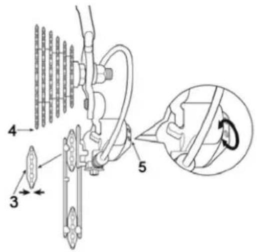
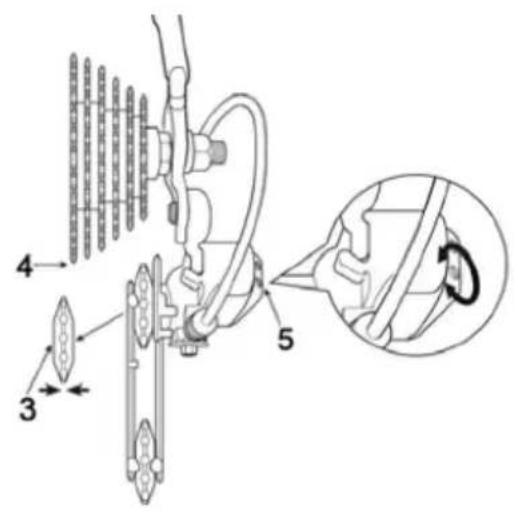
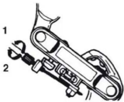
Adjustment of the outer position of the chain
Turn the upper, rear adjustment bolt for the gear mechanism until the pulley is below the outer edge of the cassette's smallest sprocket.
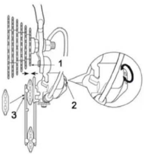
- The smallest sprocket on the cassette
- Upper adjustment screw
- Pulley
- The biggest sprocket on the cassette
- Lower adjustment screw
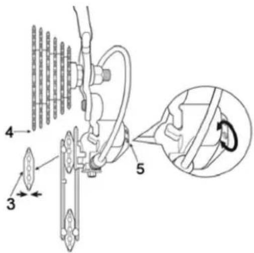
Adjustment of the inner position of the chain
Turn the adjustment bolt for the chain's inner position on the rear derailleur until the pulley is directly below the cassette's biggest sprocket
- Move the chain from the cassette's smallest to the second smallest sprocket.
- If the chain does not move onto the second smallest sprocket, turn the adjustment screw anticlockwise to increase the cable tension.
- If the chain moves past the second smallest sprocket on the cassette, turn the adjustment screw clockwise to reduce the cable tension.
- With the chain on the second smallest sprocket, increase the cable tension at the same time as rotating the crank arms. Stop tensioning the cable just before it can be heard that the chain is in position against the third smallest sprocket. The adjustment is now complete.
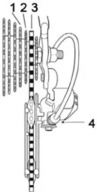
-
The third smallest sprocket on the cassette
-
The second smallest sprocket on the cassette
-
The smallest sprocket on the cassette
-
Cable adjustment screw
Cable adjustment screw
-
Anticlockwise
-
Clockwise
Lubricate all moving parts on the derailleur using molybdenum grease or similar.
TYRE CARE AND WHEEL ADJUSTMENT
- In order for the bike's tyres to function well and last a long time, it is important that they are at the correct air pressure, which is indicated on the side of the tyre.
- Locking the brakes and skidding wear out the tyres.
- The tyres must not come into contact with oil, petrol, paraffin or other agents that dissolve rubber.
- Check that the wheels are not warped and that they are correctly aligned so that the side of the tyre does not come into contact with the frame or front fork.
- Check also that the tyres are not worn or have cracks. Ensure that the tyre tread has not been worn down and that there is no damage, cracks or uneven wear on the tyre. Replace a worn or damaged tyre immediately.
- If you cycle over sharp stones, holes in the road or onto kerbstones, the tyres may puncture.
- If the bike is to be stored away for a long period, we recommend that you remove the wheels to prevent them becoming warped.
- Pump up the tyres with a foot pump or hand pump with a suitable valve connection. Check the pressure with a manometer.
- Check regularly that the spokes are correctly tensioned. Check often if you cycle a lot on uneven roads.
Removal of back wheel
- Move the chain to the cassette's smallest sprocket.
- Open the brake quick-release (if the bike has one of these).
- Slacken both the wheel axle's nuts counterclockwise.
- Lift the derailleur out a little so that you can remove the wheel more easily.
- Push the wheel forward, out of the frame.
- When fitting, put the chain over the small sprocket on the cassette and put the wheel back in position between the rear fork legs.
- Hold the wheel in this position and tighten the wheel axle nuts clockwise.
- The wheel should spin easily with very little lateral play.
- Restore the rear brake quick-release and check that the brakes are working correctly.
Back wheel with quick-release
Wheels with a quick-release are removed in the same way as a standard wheel. The only thing that is different is releasing the wheel axle from the fork. Open the quick-release by twisting the lever half a turn. Fit the back wheel according to the instructions for fitting the front wheel with quick-release. Check that the quick-release lever is in the folded-in position and that the wheel is properly secured before you begin cycling. Restore the rear brake quick-release and check that the brakes are working correctly.
Front wheel
Remove wheel axle nuts, washers and any axle locking washer. The conical bearing of the wheel axle must be adjusted so that the wheel spins easily. The conical locking nut must be properly tightened to the cone of the wheel axle so that the wheel cannot come loose. Hold the front wheel between the front fork legs and position it so that the axle locking washer and its serrations are in contact with the track in the front wheel or that the standard washers are in the correct position against the front wheel if the bike does not have wheel axle holders. Move more locking washers to the side of the wheel that is close to the fork legs if the wheel is not centred.
IMPORTANT!
The front wheel axle locking washers or washers must be positioned in the tracks in the fork legs so that the wheel sits securely in the front fork.
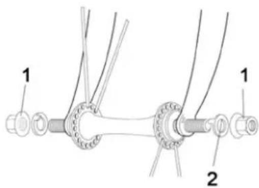
-
Nut
-
Axle locking washer
-
Front hub
-
Cone
-
Cone
-
Front fork
-
Axle locking washer
-
Axle
-
Nut
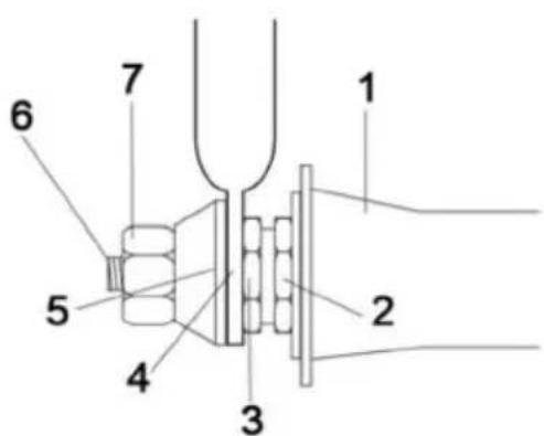
Front wheel with quick-release
- In order to remove the front wheel you must release the front wheel quick-release. Open the quick-release on the axle and pull the wheel out of the front fork.
- Remember that the quick-release needs to be on the left side when you put the wheel back. Close the quick-release and tighten the adjustment nut so that it is in close contact. Open the quick-release and tighten the adjustment nut approx. 3/4 of a turn. Close the quick-release
and check that it has made pressure marks on the fork. Adjust the quick-release again if necessary. Restore the front wheel quick-release and check that the brakes work correctly.
- The wheel must not be closer than 1.5 mm to the fork legs.
- The wheel should spin easily with very little lateral play.
- Check that the quick-release lever is in the folded-in position and that the wheel is properly secured before you begin cycling.
Quick-release lever
WARNING! Do not cycle unless the quick-release lever is fully closed and clamps securely onto the wheel. Do not let children use the bike without checking first that the quick-release is properly tightened.
MAINTAINING THE CHAIN
Lubricating the chain
The chain should be lubricated regularly; use a suitable chain oil. Check that the chain does not knock when
cycling, or is damaged. Always keep the chain oiled.
- Lubricate the chain.
- Pedal a few turns so that the oil comes in the links.
- Wipe the chain with a cloth or sponge.
Tension the chain
A chain that is not properly tensioned can be dangerous. If the chain can be moved more than 1 cm "up or down" it must be tensioned.
- Undo the nuts on the back wheel and pull the back wheel backwards.
- Tighten the nuts. Make sure the wheel is fitted straight.
- Check that the wheel is properly tightened.