
WT-4 - Photo Accessories NIKON - Free user manual and instructions
Find the device manual for free WT-4 NIKON in PDF.
| Product Type | Wireless transmitter for Nikon SLR cameras |
| Brand | Nikon |
| Model | WT-4 |
| Dimensions (L x H x W) | 135 x 96 x 48 mm |
| Weight | Approx. 150 g (without battery) |
| Power Supply | Rechargeable EN-EL3e battery or AC adapter |
| Battery Life | Approx. 2 hours of continuous use |
| Wireless Interface | Wi-Fi IEEE 802.11 b/g |
| Maximum Range | Up to 100 m in open field |
| Main Functions | FTP transfer, remote control via PC/Mac, remote shutter release |
| Compatibility | Compatible Nikon SLR cameras (D2X, D2Hs, D2H, D200, D80, etc.) |
| Maintenance and Cleaning | Clean with a soft, dry cloth. Avoid solvents. Protect from moisture. |
| Safety | Use only recommended accessories. Do not expose to extreme temperatures. |
| Spare Parts and Repairability | Contact an authorized Nikon service center for repairs. Battery and AC adapter available. |
| General Information | Designed for professional use. Canada NMB-003 Class B. |
Frequently Asked Questions - WT-4 NIKON
User questions about WT-4 NIKON
0 question about this device. Answer the ones you know or ask your own.
Ask a new question about this device
Download the instructions for your Photo Accessories in PDF format for free! Find your manual WT-4 - NIKON and take your electronic device back in hand. On this page are published all the documents necessary for the use of your device. WT-4 by NIKON.
USER MANUAL WT-4 NIKON
Wireless Transmitter
WT-4
User's Manual

Trademark Information
Macintosh and Mac OS are trademarks of Apple Computer, Inc. Microsoft, Windows, and Windows Vista are registered trademarks of Microsoft Corporation. CompactFlash is a trademark of SanDisk Corporation. All other trade names mentioned in this manual or the other documentation provided with this Nikon product are trademarks or registered trademarks of their respective holders.
Apple Public Source License
This product includes Apple mDNS source code that is subject to the terms of the Apple Public Source License located at URL http://developer.apple.com/darwin/.
Portions copyright © 1999-2003 Apple Computer, Inc. All Rights Reserved.
This file contains Original Code and/or Modifications of Original Code as defined in and that are subject to the Apple Public Source License Version 2.0 (the 'License'). You may not use this file except in compliance with the License. Please obtain a copy of the License at http://www.opensource.apple.com/apsl/ and read it before using this file.
The Original Code and all software distributed under the License are distributed on an 'AS IS' basis, WITHOUT WARRANTY OF ANY KIND, Either EXPRESS OR IMPLIED, AND APPLE HEREBY DISCLAIMS ALL SUCH WARRANTYES, INCLUDING WITHOUT LIMITATION, ANY WARRANTYES OF MERCHANTABILITY, FITNESS FOR A PARTICULAR PURPOSE, QUIET ENJOYMENT OR NON-INFRINGEMENT. Please see the License for the specific language governing rights and limitations under the License.
For Your Safety
To prevent damage to your Nikon product or injury to yourself or to others, read the following safety precautions in their entirety before using this equipment. Keep these safety instructions where all those who use the product will read them.
The consequences that could result from failure to observe the precautions listed in this section are indicated by the following symbol:

This icon marks warnings, information that should be read before using this Nikon product to prevent possible injury.
WARNING
Do not disassemble
Failure to observe this precaution could result in fire, electric shock, or other injury. Should the product break open as the result of a fall or other accident, disconnect the camera power source and take the product to a Nikonauthorized service representative for inspection.
Cut power immediately in the event of malfunction
Should you notice smoke or an unusual smell coming from the equipment, immediately unplug the AC adapter and remove the battery, taking care to avoid burns. Continued operation could result in injury. After removing the battery, take the equipment to a Nikon-authorized service representative for inspection.
Do not use in the presence of flammable gas
Failure to observe this precaution could result in explosion or fire.
Keep dry
Do not immerse in or expose to water or rain. Failure to observe this precaution could result in fire or electric shock.
Do not handle with wet hands
Failure to observe this precaution could result in electric shock.
Keep out of reach of children
Failure to observe this precaution could result in injury.
Observe proper precautions when handling batteries
Batteries may leak or explode if improperly handled. Observe the following precautions when handling batteries for use in this product:
-
Be sure the product is off before replacing the battery. If you are using an AC adapter, be sure it is unplugged.
-
Use only batteries approved for use in this equipment.
-
Do not attempt to insert the battery upside down or backwards.
-
Do not short or disassemble the battery.
-
Do not expose the battery to flame or to excessive heat.
-
Do not immerse in or expose to water.
-
Replace the terminal cover when transporting the battery. Do not transport or store with metal objects such as necklaces or hairpins.
-
Batteries are prone to leakage when fully discharged. To avoid damage to the product, be sure to remove the battery when no charge remains.
-
When the battery is not in use, attach the terminal cover and store in a cool place.
-
Immediately after use, or when the product is used on battery power for an extended period, the battery may become hot. Before removing the battery, turn the camera off and allow the battery to cool.
-
Discontinue use immediately should you notice any changes in the battery, such as discoloration or deformation.
Do not expose to high temperatures
Do not leave the device in a closed vehicle under the sun or in other areas subject to extremely high temperatures. Failure to observe this precaution could result in fire or in damage to the casing or internal parts.
Observe caution when using the antenna
When using the antenna, be careful not to put the tip of the antenna in your eye accidentally. Failure to observe this precaution could result in blindness or other visual impairment.
CD-ROMs
The CD-ROMs on which the software and manuals are distributed should not be played back on audio CD equipment. Playing CD-ROMs on an audio CD player could cause hearing loss or damage the equipment.
Follow the instructions of hospital and airline personnel
This device emits radio frequency radiation that could interfere with medical or navigational equipment. Do not use this device in a hospital or on board an airplane without first obtaining the permission of hospital or airline staff.
Notices
- No part of the manuals included with this product may be reproduced, transmitted, transcribed, stored in a retrieval system, or translated into any language in any form, by any means, without Nikon's prior written permission.
- Nikon reserves the right to change the specifications of the hardware and software described in these manuals at any time and without prior notice.
- Nikon will not be held liable for any damages resulting from the use of this product.
- While every effort has been made to ensure that the information in these manuals is accurate and complete, we would appreciate it were you to bring any errors or omissions to the attention of the Nikon representative in your area (address provided separately).
This product, which contains encryption software developed in the United States, is controlled by the United States Export Administration Regulations and may not be exported or re-exported to any country to which the United States embargoes goods. As of August 2007 the following countries were subject to embargo: Cuba, Iran, North Korea, Sudan, and Syria.
Notice for Customers in the U.S.A.
U.S.A. Federal Communications Commission (FCC) Declaration of Conformity
This device complies with Part 15 of FCC rules and RSS-Gen of IC rules.
Operation is subject to the following two conditions: (1) this device may not cause harmful interference, and (2) this device must accept any interference received, including interference that may cause undesired operation of this device.
Products that contain a radio transmitter are labeled with FCC ID and may also carry the FCC logo.

Nikon
WT-4A
FCC Radio Frequency Interference Statement
This equipment has been tested and found to comply with the limits for a Class B digital device, pursuant to Part 15 of the FCC rules. These limits are designed to provide reasonable protection against harmful interference in a residential installation. This equipment generates, uses, and can radiate radio frequency energy and, if not installed and used in accordance with the instructions, may cause harmful interference to radio communications. However, there is no guarantee that interference will not occur in a particular installation. If this equipment does cause harmful interference to radio or television reception, which can be determined by turning the equipment off and on, the user is encouraged to try to correct the interference by one or more of the following measures:
- Reorient or relocate the receiving antenna.
- Increase the separation between the equipment and receiver.
- Connect the equipment into an outlet on a circuit different from that to which the receiver is connected.
- Consult the dealer or an experienced radio/television technician for help.
CAUTIONS
Modifications
The FCC requires the user to be notified that any changes or modifications made to this device that are not expressly approved by Nikon Corporation may void the user's authority to operate the equipment.
Interface Cables
Use the interface cables sold or provided by Nikon for your equipment. Using other interface cables may exceed the limits of Class B Part 15 of the FCC rules.
Indoor operations
In accordance with 47 CFR Part 15.407 (e) U-NII, devices operating in 5.15-5.25 GHz frequency bands are restricted to indoor operations only.
Co-location
This transmitter must not be co-located or operated in conjunction with any other antenna or transmitter.
FCC/IC RF Exposure Statement
The available scientific evidence does not show that any health problems are associated with using low power wireless devices. There is no proof, however, that these low power wireless devices are absolutely safe. Low power Wireless devices emit low levels of radio frequency energy (RF) in the microwave range while being used. Whereas high levels of RF can produce health effects (by heating tissue), exposure to low-level RF that does not produce heating effects causes no known adverse health effects. Many studies of low-level RF exposures have not found any biological effects. Some studies have suggested that some biological effects might occur, but such findings have not been confirmed by additional research. This Wireless Transmitter (WT-4A), which is equipped with an SX-10WAG (FCC ID: N6C-SX10WAG / IC: 4908B-SX10WAG) Wireless LAN Module, has been tested and found to comply with FCC radiation exposure limits set forth for uncontrolled equipment and meets the FCC radio frequency (RF) Exposure Guidelines in Supplement C to OET65 and RSS-102 of the IC radio frequency (RF) Exposure rules. Please refer to the SAR test report that was uploaded to FCC website.
This WT-4A has been tested and meets the FCC RF exposure guidelines when used with the Nikon Corporation accessories supplied or designated for this product. Use of other accessories may not ensure compliance with FCC RF exposure guidelines.
Notice for Customers in the State of California, U.S.A.
WARNING: Handling the cord on this product will expose you to lead, a chemical known to the State of California to cause birth defects or other reproductive harm. Wash hands after handling.
Nikon Inc.,
1300 Walt Whitman Road, Melville, New York
11747-3064,U.S.A.Tel.:631-547-4200
Notices for Customers in Canada
CAUTION : This class B digital apparatus complies with Canadian ICES-003.
IC RSS-GEN Exposure of Humans to RF Fields
This device complies with Part 15 of FCC Rules and RSS-Gen of IC Rules.
Operation is subject to the following two conditions: (1) this device may not cause harmful interference, and (2) this device must accept any interference received, including interference that may cause undesired operation of this device.
This device has been designed to operate with an antenna having a maximum gain of 2.1 dBi. Industry Canada regulations strictly prohibit antennas with higher gain. The required antenna impedance is 50 ohms.
To reduce potential radio interference to other users, the antenna type and its gain should be so chosen that the equivalent isotropically radiated power (EIRP) is not more than that required for successful communication.
Co-location
This transmitter must not be co-located or operated in conjunction with any other antenna or transmitter.
FCC/IC RF Exposure Statement
The available scientific evidence does not show that any health problems are associated with using low power wireless devices. There is no proof, however, that these low power wireless devices are absolutely safe. Low power Wireless devices emit low levels of radio frequency energy (RF) in the microwave range while being used. Whereas high levels of RF can produce health effects (by heating tissue), exposure to low-level RF that does not produce heating effects causes no known adverse health effects. Many studies of low-level RF exposures have not found any biological effects. Some studies have suggested that some biological effects might occur, but such findings have not been confirmed by additional research. This Wireless Transmitter (WT-4A), which is equipped with an SX-10WAG (FCC ID: N6C-SX10WAG / IC: 4908B-SX10WAG) Wireless LAN Module, has been tested and found to comply with FCC radiation exposure limits set forth for uncontrolled equipment and meets the FCC radio frequency (RF) Exposure Guidelines in Supplement C to OET65 and RSS-102 of the IC radio frequency (RF) Exposure rules. Please refer to the SAR test report that was uploaded to FCC website.
This WT-4A has been tested and meets the FCC RF exposure guidelines when used with the Nikon Corporation accessories supplied or designated for this product. Use of other accessories may not ensure compliance with FCC RF exposure guidelines.
Notices for Customers in Europe
Hereby, Nikon, declares that this Wireless LAN Module (SX-10WAG) is in compliance with the essential requirements and other relevant provisions of Directive 1999/5/EC.
Notice for Customers in France
Outdoor use of wireless transceivers is prohibited in France.
□ Symbol for Separate Collection in European Countries
The following apply only to users in European countries:
This symbol indicates that this product is to be collected separately.
- This product is designated for separate collection at an appropriate collection point. Do not dispose of as household waste.
- For more information, contact the retailer or the local authorities in charge of waste management.

Table of Contents
For Your Safety.
Notices.. 3
Introduction 1
Parts of the WT-4. 2
Supported Modes 4
Workflow. 6
Preparing the Camera 7
Preparing the WT-4 8
Installing Software 10
Configuring the Network 16
Windows Vista/Creating an Ad Hoc Network 17
Windows Vista/Connecting to an Infrastructure Network 21
Windows XP/Creating an Ad Hoc Network 26
Windows XP/Connecting to an Infrastructure Network 32
Macintosh/Creating an Ad Hoc Network 38
Macintosh/Connecting to an Infrastructure Network 42
Using the WT-4 with a Computer 47
Copying Network Profiles to the Camera 48
Ad Hoc Networks 48
Infrastructure Networks 59
Upload pictures to a host computer 70
Connecting the WT-4 70
74
79
Connecting the WT-4 81
Uploading Images 85
PC Mode 90
Connecting to the Computer 90
Controlling the Camera 94
Print Mode. 97
Configuring the Printer 97
Printing Pictures 102
Uploading Images to an ftp Server 107
Creating an ftp Server 108
Windows Vista. 108
Windows XP 114
Macintosh 117
Copying Network Profiles to the Camera 119
Ad Hoc Networks 119
Infrastructure Networks 129
Connecting to the ftp Server 140
Uploading Images 145
Menu Guide 151
Mode 152
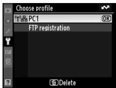
Choose Profile 152
FTP Registration (for Connection to ftp Servers Only) 153
Editing ftp Profiles. 153
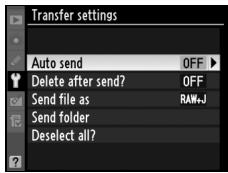
Transfer Settings (Transfer Mode Only) 169
Auto Send 169
Delete After Send? 169
Send File As. 170
Send Folder 170
Deselect All? 170
Print (Print Mode Only) 171
Device Info 172
Battery Info. 172
MAC Address 172
Firmware Version. 172
Device Settings 173
Auto Power Off 173
Format Transmitter's Memory 173
Appendices 175
Creating ftp Profiles Using Camera Menus 175
Troubleshooting 178
Glossary. 180
Specifications. 183
Index 185

Background Knowledge
This manual assumes basic knowledge of ftp servers and local area networks (LANs). For more information on installing, configuring, and using devices in a network, contact the manufacturer or network administrator.

Illustrations
The camera shown in this manual is a Nikon D3. Save where otherwise noted, all software and operating system dialogs, messages, and displays are taken from Windows Vista Ultimate or Mac OS X. Their actual appearance and content may vary with the operating system used. For information on basic computer operations, see the documentation provided with the computer or operating system.

Life-Long Learning
As part of Nikon's "Life-Long Learning" commitment to ongoing product support and education, continually-updated information is available online at the following sites:
- For users in the U.S.A.: http://www.nikonusa.com/
For users in Europe and Africa: http://www.europe-nikon.com/support - For users in Asia, Oceania, and the Middle East: http://www.nikon-asia.com/
Visit these sites to keep up-to-date with the latest product information, tips, answers to frequently-asked questions (FAQs), and general advice on digital imaging and photography. Additional information may be available from the Nikon representative in your area. See the following URL for contact information: http://nikonimaging.com/
Introduction
Thank you for your purchase of a WT-4 wireless transmitter for compatible Nikon digital cameras. The WT-4 is for use exclusively in the country of sale; operation in other jurisdictions is not guaranteed. Users who are unsure as to the country of purchase are requested to contact a Nikon-authorized service representative for more information. Please read this manual thoroughly and keep it where all those who use the product can read it.
The principal difference between the WT-4 and WT-4A/B/C/D/E is in the number of channels supported (pp. 54, 123, 155, 183); unless otherwise stated, all references to the WT-4 also apply to the WT-4A/B/C/D/E.
The following symbols and conventions are used throughout this manual:

This icon marks cautions, information that should be read before use to prevent damage to the product.

This icon marks notes, information that should be read before using the device.
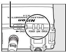
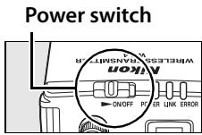
Parts of the WT-4
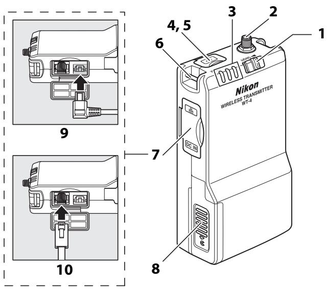
1 Power switch 71,82,91,103,141
2 Antenna connector. 8
3 Status LEDs 3,77 POWER (green/yellow), LINK (green), ERROR (orange)
4 USB connector cover 70,81,90,102,140
5 USB connector 70,81,90,102,140
6 Eyelet for strap
7 Connector cover
8 Battery chamber cover. 8
9 DC-IN connector
10 Ethernet connector

The Antenna
Always use the supplied antenna with the WT-4. Use of other antennas with this transmitter is prohibited by law.

The POWER LED
When the WT-4 is on, the POWER LED glows green to indicate that the battery is fully charged or that an AC adapter is connected. At battery levels below 10% , it will blink green to warn that the battery requires charging. When the WT-4 is turned off, the POWER LED briefly turns yellow as the product powers down.

Supplied Accessories
The following accessories are supplied with the WT-4 (batteries such as the EN-EL3e and the battery chargers such as the MH-18a are not supplied):
User's Manual (this manual)
Warranty
Software CD
Antenna
Case
Strap
USB cable
USB cable clip for the D3
USB cable clip for the D300

USB Cable Clips for D3 and D300 Cameras
The USB cable clips prevent accidental disconnections. Attach as shown below.
USB cable clip for the D3
USB cable clip for the D300
Supported Modes
The WT-4 connects the camera to wireless and Ethernet networks. Photographs on the camera can then be previewed on the computer or transmitted to an ftp server or printer and the camera controlled remotely from a computer. The WT-4 supports the following modes:
| Mode | Host | Description | See |
| Transfer mode | Computer or ftp server | Upload new or existing photographs to host. | pg. 70 |
| Thumbnail select mode | Computer | Preview the photographs in internal memory on the computer monitor before upload. | pg. 79 |
| PC mode | Computer | Control camera from computer using optional Camera Control Pro 2 software. | pg. 90 |
| Print mode | Computer | Print JPEG photographs on printer connected to network computer. | pg. 97 |
Before data can be transferred over a wireless or Ethernet network, the camera must be supplied with a network profile providing information on the host computer or ftp server.

FTP Servers
Servers can be configured using standard ftp services available with supported operating systems, such as IIS (Internet Information Services). Connection to computers on other networks via a router, Internet ftp connections and ftp servers running third-party software are not supported.

Ethernet Connection
The camera can not connect to a wireless LAN when an Ethernet cable is connected. Before connecting to a wireless LAN, turn the WT-4 off and disconnect the Ethernet cable.
No adjustments to wireless LAN settings are required when the camera is connected to a LAN by an Ethernet cable.

Routers
Connection to computers on other networks via a router is not supported.

Firewall Settings
The WT-4 uses TCP ports 20 and 21 for ftp and TCP port 15740 and UDP port 5353 when connecting to a computer. Computer firewalls must be configured to allow access to these ports, as otherwise the computer may not be able to access the WT-4.

MAC Address Filtering
If the network using MAC address filtering, the filter must be supplied with the MAC address of the WT-4. After attaching the WT-4 to the camera, choose [Device info] > [MAC address] (pg. 172) from the camera setup menu and note the wireless and Ethernet MAC addresses.
Workflow
When using the WT-4 for the first time, follow the steps below to set up the WT-4, install the required software, create a wireless network, and upload pictures to the computer.
1 Set up the WT-4 and install software (pp. 7-15).
1-1 Preparing the Camera
1-2 Preparing the WT-4
1-3 Installing Software
2 Configuring the Network (pp. 16-46).
See pages pp. 17-25 for information on Windows Vista.
See pages pp. 26-37 for information on Windows XP.
See pages pp. 38-46 for information on Mac OS X.
3 Upload pictures.
Upload pictures to a host computer/Thumbnail Select Mode/PC Mode/Print Mode (pp. 47-106).
3-1 Copying Network Profiles to the Camera
3-2 Connecting the WT-4
3-3 Uploading Images
Uploading Images to an ftp Server (pp. 107-149).
3-1 Creating an ftp Server
3-2 Copying Network Profiles to the Camera
3-3 Connecting to the ftp Server
3-4 Uploading Images
Preparing the Camera
Before using the WT-4, set the camera [USB] option to [MTP/PTP], insert a battery in the WT-4, and install the WT-4 Setup Utility and Thumbnail Selector on the host computer.
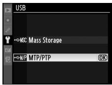
Choosing "MTP/PTP"
Before connecting the WT-4, set the camera [USB] option to [MTP/ PTP] as described below. Make sure that the camera battery is fully charged or the optional AC adapter is connected. See the camera manual for more information.
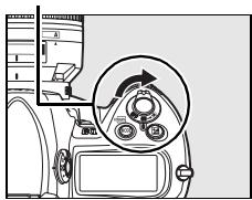
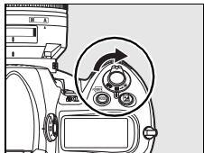
1 Turn the camera on.
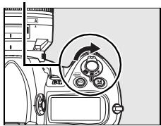
Power switch
2 Select the [USB] in the camera setup menu and choose [MTP/PTP]. See the camera manual for details.
3 Turn the camera off.
Preparing the WT-4
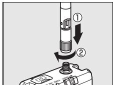
Attach the Antenna
Attach the supplied antenna to the WT-4 as shown in the diagram.
Inserting the Battery
To prevent loss of power during setup or upload, use a fully-charged battery or an optional AC adapter. The WT-4 takes one EN-EL3e rechargeable Li-ion battery; other batteries can not be used. Note that the drain on the battery is increased when the WT-4 is attached.
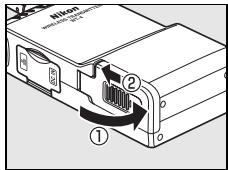
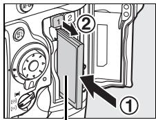
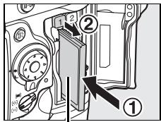
1 Open the battery chamber cover.
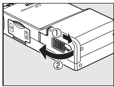
2 Using the side of the battery to push the battery latch to one side, slide the battery in until the latch clicks into place. Be sure the battery is in the correct orientation. For safety precautions and information
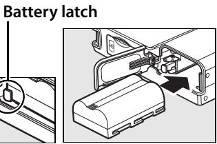
on charging the battery, see the battery and charger manuals.
3 Close the battery-chamber cover.
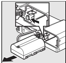
Removing the Battery
Being careful not to drop the battery, open the battery chamber cover and remove the battery as shown at right.
Stand-By Mode
When disconnected from the camera, the WT-4 will turn off automatically after the delay chosen for the [Auto power off] option in the [Wireless transmitter] menu (pg. 173), reducing the drain on the battery. Note that the WT-4 will not turn off automatically when transmitting data to a computer in thumbnail select mode (pg. 79).
Battery Level
The level of the battery inserted in the WT-4 can be determined by connecting the WT-4 to the camera (pp. 70, 81, 90, 102, 140) and checking the battery level using the [Battery info] option (pg. 172) in the camera setup menu.
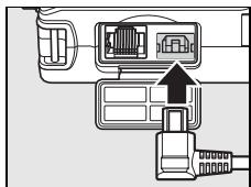
The EH-6 AC Adapter
The optional EH-6 AC adapter can also be used to power the camera when the WT-4 is connected. Connect the DC plug on the AC adapter to the WT-4 DC-IN connector, not to the camera.
Installing Software
This section describes how to install the WT-4 Setup Utility and Thumbnail Selector. The WT-4 Setup Utility is used to copy computer and printer profiles to the camera and is required when configuring the camera for connection to a computer in transfer, PC, and print modes (either the WT-4 Setup Utility or the camera menus can be used for connection to ftp servers in transfer mode; see page 175 for information on using the camera menus for ftp). Thumbnail Selector required for thumbnail select mode (pg. 79).
Follow the steps below to install the WT-4 Setup Utility and Thumbnail Selector under Windows Vista, Windows XP, or Mac OS X.
System Requirements
Before using the WT-4 or WT-4 Setup Utility CD, confirm that your system meets the following requirements:
| Camera | Nikon D3 and D300 digital single-lens reflex cameras |
| Power source | One EN-EL3e rechargeable Li-ion battery or EH-6 AC adapter (available separately) |
| OS1 | • To connect to a computer: Windows Vista Home Basic/ Home Premium/Business/Enterprise/Ultimate (32 bit), Windows XP Service Pack 1 or later (Service Pack 2 recommended) or Mac OS X version 10.3.9 or 10.4.10 (Power PC G4/G5 and Intel CPUs only). Connection to computers on other networks via a router is not supported. • To upload pictures to an ftp server: Operation has been confirmed with Windows Vista Business/Enterprise/Ultimate, Windows XP Professional Service Pack 1 or later and Mac OS X version 10.3.9 or 10.4.10. |
| Network | • Wireless: Wireless LAN access point or computer with built-in or external wireless LAN adapter (IEEE 802.11b, 802.11g, or 802.11a compliant). • Ethernet: Ethernet cable and computer with built-in or external Ethernet port (100 base-TX or 10 base-T) |
| Miscellaneous | • WT-4 Setup Utility: required to copy computer profiles to camera.² • Thumbnail Selector: required for thumbnail select mode. • CD-ROM drive: required when installing WT-4 Setup Utility/Thumbnail Selector. • USB: the supplied USB cable and a computer with built-in USB port are required when copying network profiles to camera.³ |
- For the latest information on supported operating systems, see the Nikon website for your area (pg. x).
- Not required for connection to ftp servers.
- Connect the camera directly to the computer. The camera may not function as expected when connected via a hub, extension cable, or keyboard.
Windows Vista/Windows XP
1 Start the computer and log in to an account with administrator privileges.
2 Insert the supplied installer CD in a CD-ROM drive.

Windows Vista
Under Windows Vista, an "AutoPlay" dialog will be displayed; click [Run Welcome.exe]. A "User Account Control" dialog will then be displayed; click [Allow].
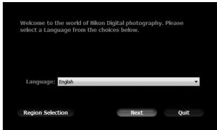
A language-selection dialog will be displayed.

If the Language Selection Dialog Is Not Displayed
If the installer does not start automatically, open the "Computer" or "My Computer" window by selecting [Computer] or [My Computer] from the [Start] menu (Windows Vista/XP) or by double-clicking the [My Computer] icon on the desktop (Windows 2000 Professional), and then double-click the CD-ROM icon.
3
Select a language and click [Next]. If the desired language is not available, click [Region Selection] to choose a different region and then choose the desired language.
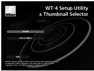
4 Click [Install].

Link to Nikon
Download trial versions of other Nikon software from a Nikon website or visit Nikon technical support websites (Internet connection required).
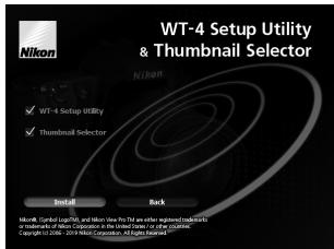
5 Select the software to be installed and click [Install]. Follow the on-screen instructions to complete installation.
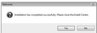
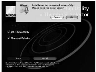
6 The dialog shown at right will be displayed when installation is complete. Click [Yes] to close the installer dialog.
7 Remove the installer CD from the CD-ROM drive. If prompted to restart the computer, follow the on-screen instructions.
Mac OS X
1 Start the computer and log in to an account with administrator privileges.
2 Insert the supplied installer CD in a CD-ROM drive. Double-click the installer CD icon on the desktop, then double-click the [Welcome] icon.
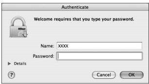
3 The dialog shown at right will be displayed; enter an administrator name and password and click [OK].
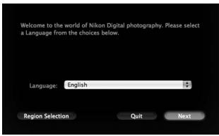
4 A language selection dialog will be displayed; select a language and click [Next]. If the desired language is not available, click [Region Selection] to choose a different region and then choose the desired language.
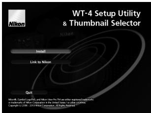
5 Click [Install].
Link to Nikon
Download trial versions of other Nikon software from a Nikon website or visit Nikon technical support websites (Internet connection required).
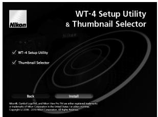
6 Select the software to be installed and click [Install]. Follow the on-screen instructions to complete installation.
7 The dialog shown at right will be displayed when installation is complete. Click [OK].
8 Remove the installer CD from the CD-ROM drive. If prompted to restart the computer, follow the on-screen instructions.
The WT-3 Setup Utility
If the WT-3 Setup Utility is installed or uninstalled after the WT-4 Setup Utility/Thumbnail Selector is installed, the WT-4 Setup Utility/Thumbnail Selector must be reinstalled.
Configuring the Network
This section describes how to create ad-hoc and infrastructure networks under Windows Vista, Windows XP, and Mac OS X.
Windows Vista
| Ad hoc Network | pg. 17 |
| Infrastructure Network | pg. 21 |
Windows XP
| Ad hoc Network | pg. 26 |
| Infrastructure Network | pg. 32 |
Macintosh
| Ad hoc Network | pg. 38 |
| Infrastructure Network | pg. 42 |
Connecting to Existing Wireless LANs
The WT-4 can also be used to connect to existing wireless LANs. Switch to the existing network after creating a new network for use with the WT-4.
Wireless Networks: Infrastructure Versus Ad-hoc
Wireless networks may be either infrastructure or ad-hoc.
- Infrastructure: Connection is via a wireless LAN access point.

WT-4

Wireless LAN access point

Host
- Ad-hoc: A peer-to-peer wireless network consisting solely of the WT-4 and the host.

WT-4

Host
□ Creating an Ad Hoc Network
1 Click the [Start] orb and select [Connect To].
![NIKON WT-4 - Click the [Start] orb and select [Connect To]. - 1](/content/2025/01/116040/images/f426524e42b26cc4949c62fd93d5e4e4b2c9bef3476729c6cb773fa75903eb65.jpg)
2 Click [Set up a connection or network].
![NIKON WT-4 - Click [Set up a connection or network]. - 1](/content/2025/01/116040/images/cfb728860ac3a88769f9ec7a32f8966141daceef0beccdf441869f28fdc22deb.jpg)
3 Select [Set up a wireless ad hoc (computer-to-computer) network] and click [Next].
![NIKON WT-4 - Select [Set up a wireless ad hoc (computer-to-computer) network] and click [Next]. - 1](/content/2025/01/116040/images/799f02b398a9b5bfb88f1f61df0e97d9430e893975c88baf3a76250e7f1b7085.jpg)
4 Click [Next].
![NIKON WT-4 - Click [Next]. - 1](/content/2025/01/116040/images/f1f6273947675efc0fe184478b7d45d605a63342b84f854adf7b206dc08713a7.jpg)
5
After entering a network name and choosing security options as described below, select [Save this network] and click [Next].
- Network name: Enter a name of up to 32 characters.
- Security type: Choose from [WEP] and [No authentication (Open)].
- Security key/Passphrase: If [WEP] is selected for [Security type], enter a security key. To enable 64-bit encryption, enter a five-character ASCII or ten-digit hexadecimal key. To enable 128-bit encryption, enter a 13-character ASCII or 26-digit hexadecimal key. ASCII keys may contain letters, punctuation, and the numbers 0–9, hexadecimal keys the numbers 0–9 and the letters a, b, c, d, e, and f.
![NIKON WT-4 - Click [Next]. - 2](/content/2025/01/116040/images/e51f646b9f24ef175ceeb0cb867e4e8ee18b5d1a4ddd7c9b060cea3e68cde5cc.jpg)
6 Click [Close].
![NIKON WT-4 - Click [Close]. - 1](/content/2025/01/116040/images/4e89a853e84b26151752fdec97fd12c2c3e032ac616cf16d5288dde2e88d42ba.jpg)
Network setup is now complete. Proceed to "Using the WT-4 with a Computer" (pg. 47) or "Uploading Images to an ftp Server" (pg. 107).
- Connecting to an Infrastructure Network
Procedures for connecting your computer to a wireless LAN access point are described here.
Configuring the Wireless LAN Access Point
Following the instructions in the manual for the wireless LAN access point, choose a network name (SS-ID), authentication, encryption, security key, and key index.
Configuring the Host
1 Click the [Start] orb and select [Connect To].
![NIKON WT-4 - Click the [Start] orb and select [Connect To]. - 1](/content/2025/01/116040/images/4b48fc88e13796756476b777a987ada873bd8c0a0b8809dfdc5f021d39ae7c0b.jpg)
2 Click [Set up a connection or network].
![NIKON WT-4 - Click [Set up a connection or network]. - 1](/content/2025/01/116040/images/d4c0fed9ef0870b690b09e652d05dba6469d202494593c3467331645caef8a73.jpg)
3 Select [Manually connect to a wireless network] and click [Next].
![NIKON WT-4 - Select [Manually connect to a wireless network] and click [Next]. - 1](/content/2025/01/116040/images/eb22ddb5497f7faa63434454e98c5d1ddedb027afd07aef4e7dd2fdd920514d4.jpg)
If [Manually connect to a wireless network] is not displayed, install the necessary driver software as described in the documentation for the wireless LAN adapter.
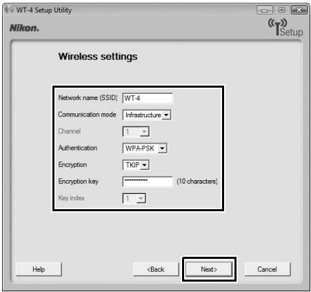
4 After entering a network name and choosing security options to match those selected for the wireless LAN access point, click [Next].
- Network name: Enter a name of up to 32 characters.
- Security type: Choose from [No authentication (Open)], [WEP], [WPA-Personal], and [WPA2-Personal]. [WPA-Enterprise], [WPA2-Enterprise], and [802.1x] can not be used with the WT-4.
- Encryption type: The type of encryption available depends on the options selected for [Security type]:
None (open system): [None]
WEP: [WEP]
WPA, WPA2: [TKIP], [AES]
- Security key/Passphrase: If [WEP] is selected for [Security type], enter a 5- or 13-character ASCII key or 10- or 26-digit hexadecimal key. Entering a five-character ASCII or ten-digit hexadecimal key enables 64-bit encryption, a 13-character ASCII or 26-digit hexadecimal key 128-bit encryption. ASCII keys may contain letters, punctuation, and the numbers 0-9, hexadecimal keys the numbers 0-9 and the letters a, b, c, d, e, and f. If [TKIP] or [AES] is selected for [Security type], enter an ASCII key of 8 to 63 characters or a 64-digit hexadecimal key.
![NIKON WT-4 - After entering a network name and choosing security options to match those selected for the wireless LAN access point, click [Next]. - 1](/content/2025/01/116040/images/e71fafdcb8eecaffaaefab043255b23c4a2d99b96469e3ab815e77d14e712a65.jpg)
5 Click [Connect to...].
![NIKON WT-4 - Click [Connect to...]. - 1](/content/2025/01/116040/images/391f5615ecdab2053dfbf8880d46c3433a879d4331059e09dce3dc10e4b25f3c.jpg)
6
Confirm that [Connected] appears next to the network name entered in Step 4 and click [Cancel].
![NIKON WT-4 - Click [Connect to...]. - 2](/content/2025/01/116040/images/f418bd1dd386ccb0f6972122fcf1315b2c03cba80ac95c0d809feb725479bb23.jpg)
Network setup is now complete. Proceed to "Using the WT-4 with a Computer" (pg. 47) or "Uploading Images to an ftp Server" (pg. 107).
Creating an Ad Hoc Network
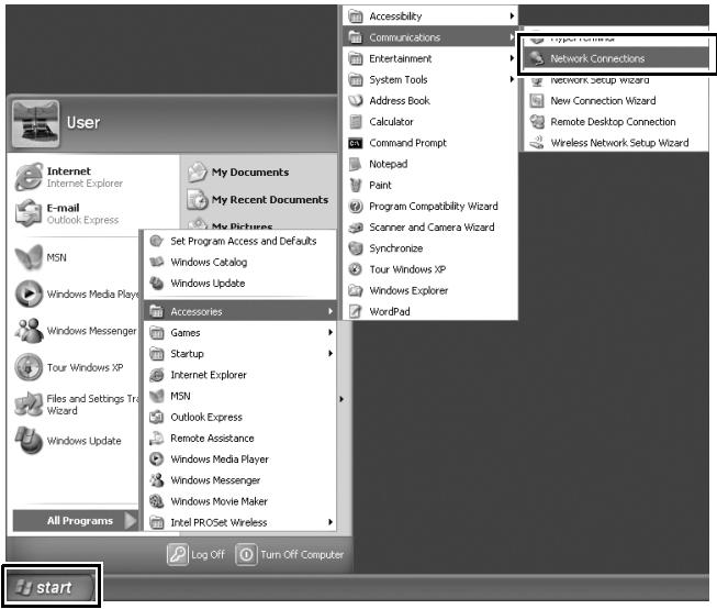
1 Click [Start] and select [All Programs] > [Accessories] > [Communications] > [Network Connections].
![NIKON WT-4 - Click [Start] and select [All Programs] > [Accessories] > [Communications] > [Network Connections]. - 1](/content/2025/01/116040/images/ec874594d4b40df7b012bb705ba677d4800faebbb17a089eba52d229672a2f23.jpg)
2 Select [Wireless Network Connection] and click [Change settings of this connection].
![NIKON WT-4 - Select [Wireless Network Connection] and click [Change settings of this connection]. - 1](/content/2025/01/116040/images/0c1cd76e178f1f6532be86503d5f07e7aad8eeb764bce3a2d1bbdad1c53c6cd0.jpg)
If a [Wireless Network Connection] icon is not displayed, install the necessary driver software as described in the documentation for the wireless LAN adapter.
3 Click the [Wireless Networks] tab.
![NIKON WT-4 - Click the [Wireless Networks] tab. - 1](/content/2025/01/116040/images/d77bae68b2dcc32f31c62cc9909e91cf893e3748d3237cf8f56c31b57efb55ef.jpg)
If a third-party wireless connection program is installed, the [Wireless Networks] tab will not be displayed. Choose authentication, encryption, and a security key as described in the documentation for the wireless LAN adapter. Make a note of the security key, as it will be required when setting up the camera.
4 Select [Use Windows to configure my wireless network settings].
![NIKON WT-4 - Select [Use Windows to configure my wireless network settings]. - 1](/content/2025/01/116040/images/0c44d0a5077e2fabfd503947532c5c8cc6237f2cffcdabfe48ad740a460f475d.jpg)
5 Click [Add].
![NIKON WT-4 - Click [Add]. - 1](/content/2025/01/116040/images/a1bf2335f8637a8d6fd958f4ec102f0b94a253b9724d56242fdfdf2daf8a73cf.jpg)
6 After entering a network name and choosing security options as described below, select [This is a computer-to-computer (ad hoc) network; wireless access points are not used] and click [OK]. Do not select [The key is provided for me automatically].
- Network name (SSID): Enter a name of up to 32 characters.
- Network Authentication: Choose from [Open] and [Shared].
- Data encryption: Choose from [WEP] and [Disabled].
- Network key: If [WEP] is selected for [Data encryption], enter a security key. To enable 64-bit encryption, enter a five-character ASCII or ten-digit hexadecimal key. To enable 128-bit encryption, enter a 13-character ASCII or 26-digit hexadecimal key. ASCII keys may contain letters, punctuation, and the numbers 0–9, hexadecimal keys the numbers 0–9 and the letters a, b, c, d, e, and f.
- Key index (advanced): If [WEP] is selected for [Data encryption], choose a key index.
![NIKON WT-4 - Click [Add]. - 2](/content/2025/01/116040/images/7daace08a469fecf3889c60f2c801eef297e7c6b28a8388d09b0b5b6ae100d1b.jpg)
7 Click [OK].
![NIKON WT-4 - Click [OK]. - 1](/content/2025/01/116040/images/c866b7870856fa103ccb2d36e0c00b0f167dc19c058b883feaca8ff51c6b0c49.jpg)
Network setup is now complete. Proceed to "Using the WT-4 with a Computer" (pg. 47) or "Uploading Images to an ftp Server" (pg. 107).
- Connecting to an Infrastructure Network
Procedures for connecting your computer to a wireless LAN access point are described here.
Configuring the Wireless LAN Access Point
Following the instructions in the manual for the wireless LAN access point, choose a network name (SS-ID), authentication, encryption, security key, and key index.
Configuring the Host
1 Click [Start] and select [All Programs] > [Accessories] > [Communications] > [Network Connections].
2 Select [Wireless Network Connection] and click [Change settings of this connection].
![NIKON WT-4 - Select [Wireless Network Connection] and click [Change settings of this connection]. - 1](/content/2025/01/116040/images/a5ab991e170bb8b0dd4e92afbff1a1b48017b22ed5c0ec57db7f179769b623ef.jpg)
If a [Wireless Network Connection] icon is not displayed, install the necessary driver software as described in the documentation for the wireless LAN adapter.
3 Click the [Wireless Networks] tab.
![NIKON WT-4 - Click the [Wireless Networks] tab. - 1](/content/2025/01/116040/images/c9e29981414aa471c48252045fd5e9757c3a434ef1295e2efd6983fb64a24411.jpg)
If a third-party wireless connection program is installed, the [Wireless Networks] tab will not be displayed. Choose authentication, encryption, and a security key as described in the documentation for the wireless LAN adapter. Make a note of the security key, as it will be required when setting up the camera.
4 Select [Use Windows to configure my wireless network settings].
![NIKON WT-4 - Select [Use Windows to configure my wireless network settings]. - 1](/content/2025/01/116040/images/53b4459be37f55875a09655c93d06a57ffe508404d2ca0cee74ea4f18c9f3c37.jpg)
5 Click [Add].
![NIKON WT-4 - Click [Add]. - 1](/content/2025/01/116040/images/cbcd3f90361b3f0a8db122dfc107701f30a1d502acbfe941f6d1eee7c93ea605.jpg)
6
After entering a network name and choosing security options to match those selected for the wireless LAN access point, remove the check from [This is a computer-to-computer (ad hoc) network; wireless access points are not used] and click [OK].
- Network name (SSID): Enter a name of up to 32 characters.
- Network Authentication: Choose from [Open], [Shared], [WPA], and [WPA-PSK].
- Data encryption: The type of encryption available depends on the options selected for [Network Authentication]:
Open, Shared: [WEP], [Disabled]
WPA, WPA-PSK: [TKIP], [AES]
- Network key: If [WEP] is selected for [Data encryption], enter a 5- or 13-character ASCII key or 10- or 26-digit hexadecimal key. Entering a five-character ASCII or ten-digit hexadecimal key enables 64-bit encryption, a 13-character ASCII or 26-digit hexadecimal key 128-bit encryption. ASCII keys may contain letters, punctuation, and the numbers 0-9, hexadecimal keys the numbers 0-9 and the letters a, b, c, d, e, and f. If [TKIP] or [AES] is selected for [Data encryption], enter an ASCII key of 8 to 63 characters or a 64-digit hexadecimal key.
![NIKON WT-4 - Click [Add]. - 2](/content/2025/01/116040/images/eab439e6ac8fe2c8212fd7aca4530728f0524598aaf4f503e07fedcf583a4831.jpg)
7 Click [OK].
![NIKON WT-4 - Click [OK]. - 1](/content/2025/01/116040/images/eac5d0119842cb3b1e45a4f99bf08fe09487236e553016436b2cb5acfa0518f9.jpg)
Network setup is now complete. Proceed to "Using the WT-4 with a Computer" (pg. 47) or "Uploading Images to an ftp Server" (pg. 107).
Creating an Ad Hoc Network
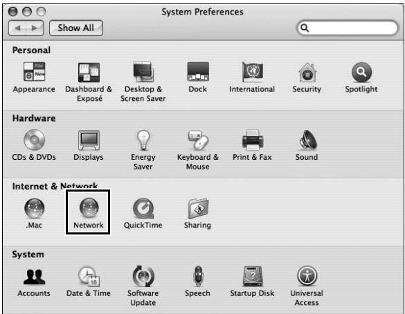
1 Open [System Preferences] and click [Network].
![NIKON WT-4 - Open [System Preferences] and click [Network]. - 1](/content/2025/01/116040/images/8ddf047e4c8c2c8276fed1aa60f4f4a5e397e7e42ce942e529a2f92b85c660ca.jpg)
2 Choose [Network Port Configurations] from the [Show] menu.
![NIKON WT-4 - Choose [Network Port Configurations] from the [Show] menu. - 1](/content/2025/01/116040/images/d735823e8805bd40befe196a3783e4663613022540130b7e097eb81f0b45dd9e.jpg)
3 Enable [AirPort], drag it to the top of the list, and click [Apply Now].
![NIKON WT-4 - Enable [AirPort], drag it to the top of the list, and click [Apply Now]. - 1](/content/2025/01/116040/images/fa1ed6bc5c09a1dd45077ea7fe3d9c1d9dc96f475d86b822622aeb2777fc25f7.jpg)
4 Click the AirPort status icon in the menu bar and select [Turn AirPort On].
![NIKON WT-4 - Enable [AirPort], drag it to the top of the list, and click [Apply Now]. - 2](/content/2025/01/116040/images/58ba214d910e50d8458bb3efcff82e1372a7df824a4aadfb381acd24b624f51a.jpg)
5 Click the AirPort status icon in the menu bar and select [Create Network...].
![NIKON WT-4 - Enable [AirPort], drag it to the top of the list, and click [Apply Now]. - 3](/content/2025/01/116040/images/0ea6b67d269a2df73041be477821a901446924a10700cac18ac33dfa939f8be6.jpg)
6 After choosing a network name and channel and adjusting encryption and password options as described below, click [OK].
- Name: Enter a name of up to 32 characters.
- Channel: Choose a channel.
- Enable encryption (using WEP): Select this option to enable WEP encryption.
- Password: If WEP encryption is enabled, enter a security key. The length of the key depends on the option selected for [WEP key]:
[40-bit (more compatible)]: Enter a five-character ASCII or ten-digit hexadecimal key.
[128-bit]: Enter a 13-character ASCII or 26-digit hexadecimal key.
ASCII keys may contain letters, punctuation, and the numbers 0-9, hexadecimal keys the numbers 0-9 and the letters a, b, c, d, e, and f.
- WEP key: Choose the length of the WEP key.
![NIKON WT-4 - After choosing a network name and channel and adjusting encryption and password options as described below, click [OK]. - 1](/content/2025/01/116040/images/63fcc976b758be08ba0cffa82927f6dbbf6fe23f82460dc5c1961bd1dd61a321.jpg)
Network setup is now complete. Proceed to "Using the WT-4 with a Computer" (pg. 47), "Uploading Images to an ftp Server" (pg. 107).
- Connecting to an Infrastructure Network
Procedures for connecting your computer to a wireless LAN access point are described here.
Configuring the Wireless LAN Access Point
Following the instructions in the manual for the wireless LAN access point, choose a network name (SS-ID), authentication, encryption, security key, and key index.
Configuring the Host
1 Open [System Preferences] and click [Network].
2 Choose [Network Port Configurations] from the [Show] menu.
![NIKON WT-4 - Choose [Network Port Configurations] from the [Show] menu. - 1](/content/2025/01/116040/images/782a802dc7552452bf59f0ecfeacc5496189fa231c04f350be0c91a166217bbb.jpg)
3 Enable [AirPort], drag it to the top of the list, and click [Apply Now].
![NIKON WT-4 - Enable [AirPort], drag it to the top of the list, and click [Apply Now]. - 1](/content/2025/01/116040/images/b8b454d526e6850255f60195099a03a2e86be401ad2689c0bbcc146b2c276ba9.jpg)
4 Choose [AirPort] from the [Show] menu.
![NIKON WT-4 - Choose [AirPort] from the [Show] menu. - 1](/content/2025/01/116040/images/632d44b6f355be4b3962b0e32544f1ca629dd8d972ec6d7d07b2d51a6746aaa7.jpg)
5 Choose [Preferred networks] from the [By default, join] menu and click [+] .
![NIKON WT-4 - Choose [Preferred networks] from the [By default, join] menu and click [+] . - 1](/content/2025/01/116040/images/192002f56da13101254a8eee6661c43e239242db94b60427d54aeb71b0ce5abf.jpg)
6 Enter the network name and other settings for the wireless access point and click [OK].
Network Name: Enter a name of up to 32 characters.
- Wireless Security: Choose from [None], [WEP Password], [WEP 40/128-bit hex], [WEP 40/128-bit ASCII], [WPA Personal], and [WPA2 Personal]. [LEAP], [WPA Enterprise], [WPA2 Enterprise], and [802.1X WEP] can not be used with the WT-4.
- Password: If WEP or WPA encryption is enabled, enter a security key. The length of the key depends on the option selected for [Wireless Security]:
[WEP Password]: Enter a five- or thirteen-character key.
[WEP 40/128 bit (hex)]: Enter a 10- or 26-digit hexadecimal key. Hexadecimal keys may contain only the numbers 0-9 and the letters a, b, c, d, e, and f.
[WEP 40/128 bit (ASCII)]: Enter a five- or thirteen-character key.
- [WPA-Personal], [WPA2-Personal]: Enter a key of 8 to 63 characters.
![NIKON WT-4 - Enter the network name and other settings for the wireless access point and click [OK]. - 1](/content/2025/01/116040/images/7216d6da6fb416251747b7a96d78d210762075aff6fe0b4f7800f08f731d62c0.jpg)
7 Click [Apply Now].
![NIKON WT-4 - Click [Apply Now]. - 1](/content/2025/01/116040/images/309e64125d1a494d25e9cef4c6321f6b3933848be8b29eff92eef3bf6c148a07.jpg)
Network setup is now complete. Proceed to "Using the WT-4 with a Computer" (pg. 47) or "Uploading Images to an ftp Server" (pg. 107).
Using the WT-4 with a
Computer
The WT-4 can be used in the following modes:
Transfer mode: Upload images to a computer.
Thumbnail select mode: Use the supplied Thumbnail Selector software to preview the photographs on the camera as small thumbnail images and select pictures for upload.
PCmode: Control the camera from a computer using Camera Control Pro 2 (available separately).
Print mode: Print JPEG images from the camera to a printer connected to a network computer.
The workflow for each of these modes is shown below.
1 Copying Network Profiles to the Camera (pg. 48).
- Ad Hoc Networks (pg. 48)
Infrastructure Networks (pg. 59)

2 Upload pictures.
Upload pictures to a host computer (pp. 70-78).
2-1 Connecting the WT-4
2-2 Uploading Images
Thumbnail Select Mode (pp. 79-89).
2-1 Connecting the WT-4
2-2 Uploading Images
PC Mode (pp. 90-96).
2-1 Connecting to the Computer
2-2 Controlling the Camera
Print Mode (pg. 97-106).
2-1 Configuring the Printer
2-2 Printing Pictures
Copying Network Profiles to the Camera
Ad Hoc Networks
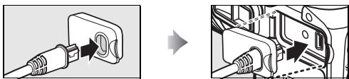
1 Connect the UC-E4 as shown below.

2 Turn the camera on.
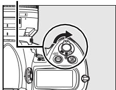
Power switch
3 Turn the computer on and start the WT-4 Setup Utility.
- Windows: Double-click the [WT-4 Setup Utility] icon on the desktop.
- Macintosh: Click the [WT-4WirelessSetup] icon in the Dock.
4 The dialog shown below will be displayed; click [Next].
![NIKON WT-4 - The dialog shown below will be displayed; click [Next]. - 1](/content/2025/01/116040/images/a26564f5b86fa175b8f47bdfaccb49729b4114e7107a7af5145b7112f7b85c08.jpg)
5 Select [Add/Edit profiles] and click [Next].
![NIKON WT-4 - Select [Add/Edit profiles] and click [Next]. - 1](/content/2025/01/116040/images/4652f22756879561b64a4033335a45f5708620e6d9bcf1ae40abd742290fb2dc.jpg)
![NIKON WT-4 - Select [Add/Edit profiles] and click [Next]. - 2](/content/2025/01/116040/images/3bb9395397449b1032a6bd7267c3d0b585f398c1ab8c60a6f52f2d713da2fb95.jpg)
The "Select Action" Dialog
The other options in the "Select Action" dialog are described below. Note that the camera need not be connected to a computer to choose a printer or change the upload folder.
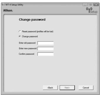
- Change password: The dialog shown at right will be displayed. By default, no password is required to change device profiles using the WT-4 Setup Utility. A password can be added by selecting [Change password]. If the camera is later connected to a different computer, a password prompt will be displayed. Once the correct password has been entered, the prompt will not be displayed again. To change an existing
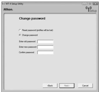
password, enter the old password before typing the new password. To remove the password, select [Reset password (profiles will be lost)] and click [Next]. Please note that resetting the password deletes all existing device profiles from the camera. Click [Back] to exit without changing password settings.
-
Setup wireless printer: By default, the system default printer for the host computer will be used when printing pictures. To choose a different printer, select [Setup wireless printer] (pg. 97).
-
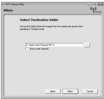
Setup picture folder: The dialog shown at right will be displayed. This screen allows you to select the destination folder when downloading images to your computer in transfer mode. Click the [...] button to select the destination for images uploaded to the computer (the camera need not be connected for this operation). The default destination is the "WT-4" folder in the "Pictures" (Windows Vista/Mac OS X) or "My Pictures" (Windows XP).
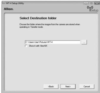
- Show it with ViewNX: If this option is selected, uploaded images will be displayed in ViewNX when the connection with the WT-4 is terminated. This option only available if ViewNX is installed.
6 Select [Add new profile] and click [Next].
![NIKON WT-4 - Select [Add new profile] and click [Next]. - 1](/content/2025/01/116040/images/8045bf03df5cdb40e17174c3569637bed6ce32105f78792baea8da43916eb010.jpg)
7 Enter the following information and click [Next]:
- Profile name: Enter a name of up to 16 characters.
- Profile type: Choose [Computer].
- Interface type: Choose [Wireless & Ethernet] for networks that include wireless, or [Ethernet only] for Ethernet-only networks.
![NIKON WT-4 - Enter the following information and click [Next]: - 1](/content/2025/01/116040/images/60e29441a7660b717d90f9d7db97c0ba2c100fff5d9f02e6341959add44a404c.jpg)
8 Select [Manual setup] and click [Next].
![NIKON WT-4 - Select [Manual setup] and click [Next]. - 1](/content/2025/01/116040/images/b639f9f9e958917ca376a358c70fcdc7466912823ba04544115051ccb752e9cd.jpg)
![NIKON WT-4 - Select [Manual setup] and click [Next]. - 2](/content/2025/01/116040/images/66ecb597d4e580ef419eeb39f4c7423ec7b70b578ca3be8d05dc1bf587a84a0e.jpg)
"Automatic Setup"
Choose [Automatic setup (recommended)] when using a new network for the first time. The following dialog will be displayed; select [Use Ad-hoc network] and click [Next] to proceed to Step 11 (pg. 57).
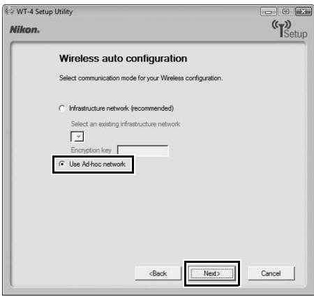
The [Automatic setup (recommended)] option can not be used with existing network profiles, third-party wireless LAN adapters, networks using static IP addresses, or Windows XP SP1 or Mac OS X.
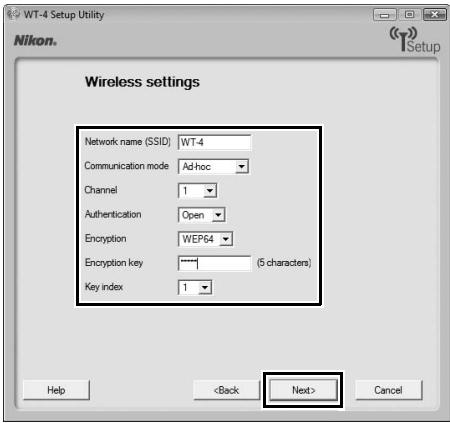
9 Enter the following information and click [Next].
- Network name (SSID): Enter a network name or choose from a list of existing networks. Do not change the name if it is supplied automatically.
- Communication mode: Select [Ad hoc].
- Channel: Select a channel. Note that if a matching SSID is detected on a different channel, the WT-4 may change the channel automatically.
- Authentication: Choose the type of authentication used on the network. In ad-hoc mode, the camera supports open system and shared key authentication.
- Encryption: The type of encryption used on the network. Choose from [None] (open networks only), 64-bit WEP, and 128-bit WEP.
- Encryption key: If the network uses encryption, enter the network key. The number of characters required depends on the type of key used:
| WEP (64-bit) | WEP (128-bit) | |
| Number of characters (ASCII) | 5 | 13 |
| Number of characters (hex) | 10 | 26 |
- Key Index: If [WEP64] or [WEP128] is selected for [Encryption], choose a key index (the default index is [1]). A key index is not required when [None] is selected.
10 Select [Obtain IP address automatically] and click [Next].
- Obtain IP address automatically: Select this option if the network is configured to supply IP addresses automatically. If the network does not include a DHCP server, addresses will be supplied by Auto IP (pg. 180).
- IP address: If the network is configured for manual IP addressing, enter an IP address for the WT-4.
- Subnet mask: If the network is configured for manual IP addressing, enter a subnet mask for the WT-4.
- Default gateway: If the network requires a gateway address, select this option and enter the address supplied by the network administrator. This option applies only if [FTP Server] is selected for [Profile type] in Step 7.
- DNS Server: If a Domain Name Server exists on the network, select this option and enter the address supplied by the network administrator. This option applies only if [FTP Server] is selected for [Profile type] in Step 7.
![NIKON WT-4 - Select [Obtain IP address automatically] and click [Next]. - 1](/content/2025/01/116040/images/f54ee9ab8b66f9d8713050b9291fcfc20ab9b7cf20fbc146aa8da0d9fd6bae4c.jpg)
11 Confirm that settings are correct and click [Next].
![NIKON WT-4 - Confirm that settings are correct and click [Next]. - 1](/content/2025/01/116040/images/c1bc2e88609ba1852ccd277a1a818acf978cf741da698b998e2035db6e83f88b.jpg)
12 Select [Finish wizard] and click [Next].
![NIKON WT-4 - Select [Finish wizard] and click [Next]. - 1](/content/2025/01/116040/images/c6d9cdc8e1de406c737b664650e85c873dbbea584521019d992bc9fc28de2132.jpg)
13 Turn the camera off and disconnect the USB cable.
![NIKON WT-4 - Select [Finish wizard] and click [Next]. - 2](/content/2025/01/116040/images/d6ce753e13b43c6ea37eaeee476c67222c10d99f83e3450a8ec87e04257e7509.jpg)
![NIKON WT-4 - Select [Finish wizard] and click [Next]. - 3](/content/2025/01/116040/images/df3e5def0917d9081adef9ee45a086519f93bc9857104cc21a00dd46a4684f44.jpg)
The network profile has now been copied to the camera. Proceed to "Upload pictures to a host computer" (pg. 70), "Thumbnail Select Mode" (pg. 79), "PC Mode" (pg. 90) or "Print Mode" (pg. 97).
1 Connect the UC-E4 as shown below.

2 Turn the camera on.
Power switch
3 Turn the computer on and start the WT-4 Setup Utility.
- Windows: Double-click the [WT-4 Setup Utility] icon on the desktop.
- Macintosh: Click the [WT-4WirelessSetup] icon in the Dock.
4 The dialog shown below will be displayed; click [Next].
![NIKON WT-4 - The dialog shown below will be displayed; click [Next]. - 1](/content/2025/01/116040/images/1f2162e4a1d2426b18178b53d588db0145b078fff357c02cae62f8ec39eabb37.jpg)
5 Select [Add/Edit profiles] and click [Next].
![NIKON WT-4 - Select [Add/Edit profiles] and click [Next]. - 1](/content/2025/01/116040/images/c636ec0af77f391d3dcc1c67a5c8b8c5288874626dcfa4148ee03779da2641ae.jpg)
![NIKON WT-4 - Select [Add/Edit profiles] and click [Next]. - 2](/content/2025/01/116040/images/ab80922bb991bb912b6e17da124905f41647e50299a5f1c43c8727d4e7d445da.jpg)
The "Select Action" Dialog
The other options in the "Select Action" dialog are described below. Note that the camera need not be connected to a computer to choose a printer or change the upload folder.
- Change password: The dialog shown at right will be displayed. By default, no password is required to change device profiles using the WT-4 Setup Utility. A password can be added by selecting [Change password]. If the camera is later connected to a different computer, a password prompt will be displayed. Once the correct password has been entered, the prompt will not be displayed again. To change an existing
password, enter the old password before typing the new password. To remove the password, select [Reset password (profiles will be lost)] and click [Next]. Please note that resetting the password deletes all existing device profiles from the camera. Click [Back] to exit without changing password settings.
-
Setup wireless printer: By default, the system default printer for the host computer will be used when printing pictures. To choose a different printer, select [Setup wireless printer] (pg. 97).
-
Setup picture folder: The dialog shown at right will be displayed. This screen allows you to select the destination folder when downloading images to your computer in transfer mode. Click the [...] button to select the destination for images uploaded to the computer (the camera need not be connected for this operation). The default destination is the [WT-4] folder in the "Pictures" (Windows Vista/Mac OS X) or "My Pictures" (Windows XP).
- Show it with ViewNX: If this option is selected, uploaded images will be displayed in ViewNX when the connection with the WT-4 is terminated. This option only available if ViewNX is installed.
6 Select [Add new profile] and click [Next].
![NIKON WT-4 - Select [Add new profile] and click [Next]. - 1](/content/2025/01/116040/images/e3642fc4d8eda35e99c3e8d00d322926456a6542db556db839bb2cc7922215b1.jpg)
7 Enter the following information and click [Next]:
- Profile name: Enter a name of up to 16 characters.
- Profile type: Choose [Computer].
- Interface type: Choose [Wireless & Ethernet] for networks that include wireless, or [Ethernet only] for Ethernet-only networks.
![NIKON WT-4 - Enter the following information and click [Next]: - 1](/content/2025/01/116040/images/28120a73507264fc8ad1928107587894b35ee6e23042b4a44fe48cddaf8336a8.jpg)
Select [Manual setup] and click [Next].
![NIKON WT-4 - Select [Manual setup] and click [Next]. - 1](/content/2025/01/116040/images/0e40ae43065bff171b71d77162373d9e333bfb2b74ab9d3d161ecfff72af4d63.jpg)
8
![NIKON WT-4 - Select [Manual setup] and click [Next]. - 2](/content/2025/01/116040/images/2a261326d8b941efec8c903ef9921494777feec1fa7269b61c03198623c147e7.jpg)
"Automatic Setup"
Choose [Automatic setup (recommended)] when using a new network for the first time. The following dialog will be displayed. Select [Infrastructure network (recommended)] (if more than one infrastructure network exists, choose a network from the pull-down menu) and click [Next] to proceed to Step 11 (pg. 68).
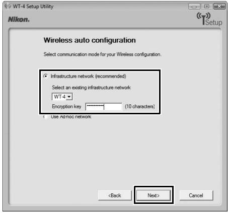
The [Automatic setup (recommended)] option can not be used with existing network profiles, third-party wireless LAN adapters, networks using static IP addresses, Windows XP SP1, Mac OS X, or computers that are not configured for connection to a wireless LAN access point.
9
Enter the following information and click [Next].
- Network name (SSID): Enter a network name or choose from a list of existing networks. Do not change the name if it is supplied automatically.
- Communication mode: Select [Infrastructure].
- Authentication: Choose the authentication used on the network. In infrastructure mode, the camera supports WPA-PSK, WPA2-PSK, open system, and shared key authentication.
- Encryption: Choose the encryption used on the network. The options available depend on the authentication used:
Open: None, 64- or 128-bit WEP
Shared: 64- or 128-bit WEP
WPA-PSK: TKIP, AES
WPA2-PSK: AES
- Encryption key: If the network uses encryption, enter the network key. The number of characters required depends on the type of key used:
| WEP (64-bit) | WEP (128-bit) | TKIP, AES | |
| Number of characters (ASCII) | 5 | 13 | 8-63 |
| Number of characters (hex) | 10 | 26 | 64 |
- Key Index: If [WEP64] or [WEP128] is selected for [Encryption], choose a key index (the default index is [1]). A key index is not required when [None] is selected.
10 Select [Obtain IP address automatically] and click [Next].
- Obtain IP address automatically: Select this option if the network is configured to supply IP addresses automatically. If the network does not include a DHCP server, addresses will be supplied by Auto IP (pg. 180).
- IP address: If the network is configured for manual IP addressing, enter an IP address for the WT-4.
- Subnet mask: If the network is configured for manual IP addressing, enter a subnet mask for the WT-4.
- Default gateway: If the network requires a gateway address, select this option and enter the address supplied by the network administrator. This option applies only if [FTP Server] is selected for [Profile type] in Step 7.
- DNS Server: If a Domain Name Server exists on the network, select this option and enter the address supplied by the network administrator. This option applies only if [FTP Server] is selected for [Profile type] in Step 7.
![NIKON WT-4 - Select [Obtain IP address automatically] and click [Next]. - 1](/content/2025/01/116040/images/58fb9122dc48054dda9a9c31d6e05680fb75f6d059093c27da94b31b8c47c083.jpg)
Choosing an IP Address
Select [Obtain IP address automatically] if a DHCP server is present on the network, otherwise deselect this option and enter an IP address different from that of the computer or wireless LAN access point.
11 Confirm that settings are correct and click [Next].
![NIKON WT-4 - Confirm that settings are correct and click [Next]. - 1](/content/2025/01/116040/images/fed1e96c4050d7d7ba14d805dc27d911d1493e8629bc40d33292cf337ca3bbe9.jpg)
12 Select [Finish wizard] and click [Next].
![NIKON WT-4 - Select [Finish wizard] and click [Next]. - 1](/content/2025/01/116040/images/0b9eeb6c24f84b5768552b8d3b0301b0473879181e62303ea4a1c5d90b3e4e6a.jpg)
13 Turn the camera off and disconnect the USB cable.
![NIKON WT-4 - Select [Finish wizard] and click [Next]. - 2](/content/2025/01/116040/images/f969bbb6e2aa5212205d52f2daa4a5d257c173fca2a33ffa7cc9b84d8a5a4f38.jpg)
![NIKON WT-4 - Select [Finish wizard] and click [Next]. - 3](/content/2025/01/116040/images/ca18d2fdd2534bcff45fa6bc4acdfab3edf5bb1eb188806ff89290d3c302cd0f.jpg)
The network profile has now been copied to the camera. Proceed to "Upload pictures to a host computer" (pg. 70), "Thumbnail Select Mode" (pg. 79), "PC Mode" (pg. 90), "Print Mode" (pg. 97).
Upload pictures to a host computer
Connecting the WT-4
Before connecting the WT-4, select [MTP/PTP] for the [USB] option in the camera setup menu (pg. 7) and confirm that the host computer is running and the user is logged in.
1 Turn the camera off and insert the memory card containing the pictures to be sent (if the camera is equipped with multiple memory card slots, the card can be inserted into any slot).
Front
To access the network via Ethernet, connect the Ethernet cable (pg. 2). Note that wireless transfer is disabled while an Ethernet cable is connected. Disconnect the Ethernet cable before accessing a wireless network. Turn the WT-4 off before connecting or disconnecting the Ethernet cable.
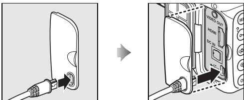
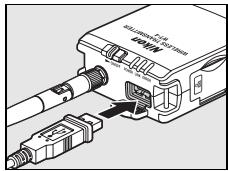
2 Open the WT-4 USB connector cover and connect the USB cable from the WT-4 to the camera USB connector.

3 Turn the camera on.
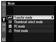
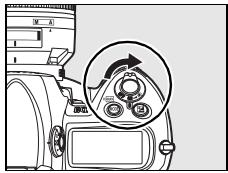
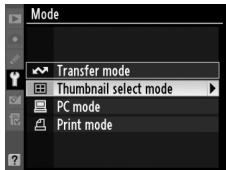
4 Select [Transfer mode] for the [Wireless transmitter] > [Mode] option in the camera setup menu (pg. 152).
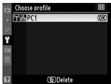
5 A list of available connection profiles will be displayed. Highlight the desired profile and press © .
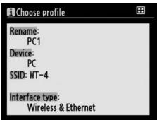
Viewing Profile Information
Press the camera O-m (?) button to view information on the selected profile.

6 Select [Wireless transmitter] > [Transfer settings] and adjust settings as described on pages pp. 169-170.
7 Turn on the WT-4.

Power switch
8 Confirm that the selected profile is displayed in green in the top level of the wireless transmitter menu. For information on what to do if an error is displayed, see "Troubleshooting" (pg. 178).


Ad-hoc Networks (Windows Vista)
To connect to an ad-hoc network using Windows Vista, turn the WT-4 on and follow the steps below on the computer.
1 Click the "Start" orb and select [Connect To].
![NIKON WT-4 - Click the "Start" orb and select [Connect To]. - 1](/content/2025/01/116040/images/1ea53a9b7384c039f62a6874199021eaafd9feed86b78fdc14433641771a0647.jpg)
2 Select the network name (SSID) for the WT-4 and click [Connect].
![NIKON WT-4 - Select the network name (SSID) for the WT-4 and click [Connect]. - 1](/content/2025/01/116040/images/8a209947e7cb1b6a3d51516f7684239bc9a89f8bf6533d1cd2e6218547ffd089.jpg)
3 Enter the network security key and click [Connect].
![NIKON WT-4 - Enter the network security key and click [Connect]. - 1](/content/2025/01/116040/images/cbd688d57c4db769d82724501b73634dbf145cb3f0fb3d9656192c6110acffef.jpg)
4 Click [Close].
![NIKON WT-4 - Click [Close]. - 1](/content/2025/01/116040/images/f87b381c364ec15b03cfe2b83391a1743f7ca5550f794ac78b7cee8026ba72ac.jpg)
Uploading Images
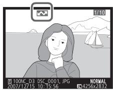
1 Press the l button to view pictures on the memory card.
Display the first picture to be sent in single-image playback or highlight it in the thumbnail list.
2 While pressing the button, press the center of the multi selector (D3) or the button (D300). The image will be marked with a white "send" icon and transmission will begin immediately. During upload, images are marked with

a green "sending" icon. Repeat this process to send additional images (pictures will be sent in the order selected).
Images that have been successfully uploaded are marked with a blue "sent" icon. Images can be resent by pressing the center of the multi selector while pressing the 3 button (D3) or the button (D300) to change the blue "sent" icon to a white "send" icon.

D300 Retouch Options
When [Wireless transmitter] > [Mode] > [Transfer mode] is selected in the camera setup menu and the WT-4 is on, the © button on the D300 is used during playback to select pictures for upload, preventing it from being used to select pictures for other operations, such as side-by-side comparison. To restore normal operation, select another option for [Wireless transmitter] > [Mode].
3 Turn the WT-4 off and wait for the POWER LED (pg. 3) to turn from green to yellow and then go out. Disconnect the USB cable. The destination folder selected in the Setup Utility (pg. 50) will open automatically when the connection between the computer and the WT-4 is terminated.

Interrupting Transmission
To cancel transmission of images marked with a white "send" icon or green "sending" icon, select the images during playback and press the center of the multi selector while pressing the button (D3) or the button (D300). The icon will be removed. Any of the following actions will also interrupt transmission:
- Turning the camera or WT-4 off
- Selecting [Yes] for [Wireless transmitter] > [Transfer settings] > [Deselect all?]
During Upload
Do not remove the memory card or disconnect the Ethernet cable during upload.
Voice Memos
Voice memos can not be uploaded separately, but will be included when associated pictures are transmitted. Voice recordings can not be selected for upload.
Loss of Signal
Transmission may be interrupted if the signal is lost (pg. 77). Transmission can be resumed by turning the WT-4 off and then on again.
Turning the Camera Off
"Send" marking will be saved if the camera or WT-4 is turned off while transmission is in progress. Transmission of images marked with a "send" icon will resume when the camera or WT-4 is turned on.
Transfer Status
During playback, the status of images selected for upload is shown as follows:
: "Send"
Images that have been selected for upload are marked with a white icon.
: "Sending"
A green icon is displayed during upload.

: "Sent"
Images that have been uploaded successfully are marked with a blue icon.

Removing the "Send," "Sending," and "Sent" Icons
"Send," "sending," and "sent" icons can be removed from all images by selecting [Yes] for [Wireless transmitter] > [Transfer settings] > [Deselect all?] (pg. 170).
Network Status
The status of the link between the host and the WT-4 is shown by the status LEDs and by the display in the top level of the wireless transmitter menu.
The Status LEDs
The POWER LED lights when the WT-4 is on. Signal quality is shown by the LINK LED: the faster the LED blinks, the better the signal and the faster data can be transmitted. The ERROR LED blinks to show that an error has occurred.
Status LEDs
| Status | POWER | LINK | ERROR |
| WT-4 off | ● (off) | ● (off) | ● (off) |
| USB cable not connected | ○ (on) | ● (off) | ● (off) |
| Connecting to host | ○ (on) | ○ (on) | ● (off) |
| Waiting to send or sending data | ○ (on) | (blinks) | ● (off) |
| Connection error | (blinks) | ● (off) | (blinks) |
| WT-4 hardware or battery malfunction | (blinks) | (blinks) | (blinks) |
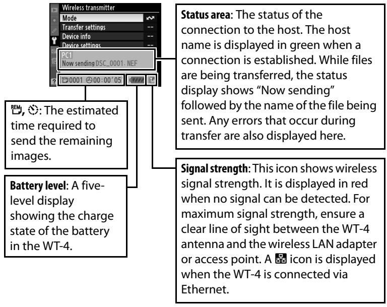
The Status Display
Network status can also be viewed in the top level of the wireless transmitter menu.
Thamburger Select Mode
Photographs taken with [Thumbnail select mode] selected for [Mode] are saved both to the camera memory card and to the WT-4 wireless transmitter's internal memory. Small thumbnail previews of the copies on the WT-4 are transmitted to the computer for display in the supplied Thumbnail Selector software, making it possible to select photographs for transfer to the computer.
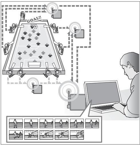
Example
Suppose multiple photographers using cameras equipped with WT-4 wireless transmitters are stationed around the field at a soccer game, recording the action from different angles.
Thumbnail previews are transmitted over a wireless network to a computer, where Thumbnail Selector can display photographs from up to five cameras in real time. Workers at the computer can select the thumbnails they prefer and upload only these selected images to the computer.
Thamburger Selector
Thumbnail Selector displays the images stored in the WT-4 as small thumbnail previews. Photographs from up to five cameras can be previewed instantly and selected for upload as desired. For more information, see the online help for Thumbnail Selector.

Internal Memory
The WT-4 is equipped with 1 GB of internal memory. Only the most recent photographs are stored; if memory is full, the oldest photographs will be deleted as necessary to make room for new pictures. The photographs on the WT-4 are not affected when a new memory card is inserted in the camera, and memory cards can be freely exchanged without concern for whether the images they contain have been uploaded to the computer.
Photographs can be deleted from the WT-4 by formatting internal memory as described on page 173. All photographs stored in internal memory will be deleted.
If a large number of photographs are taken in a single burst, some time may be required to copy the pictures to internal memory. The number of photographs remaining to be copied can be viewed by selecting [Wireless transmitter] in the setup menu after shooting.
The camera memory card access lamp will light while photographs are being copied to internal memory. To prevent damage to internal memory, do not remove the battery from the camera or WT-4 or disconnect the AC adapter or USB cable while the access lamp is lit. If the WT-4 is turned off while the access lamp is lit, the WT-4 will remain on until all pictures have been transferred to internal memory.
Connecting the WT-4
Before connecting the WT-4, select [MTP/PTP] for the [USB] option in the camera setup menu (pg. 7) and confirm that the host computer is running.
1 Turn the camera off and insert the memory card containing the pictures to be sent (if the camera is equipped with multiple memory card slots, the card can be inserted into any slot).
Front
To access the network via Ethernet, connect the Ethernet cable (pg. 2). Note that wireless transfer is disabled while an Ethernet cable is connected. Disconnect the Ethernet cable before accessing a wireless network. Turn the WT-4 off before connecting or disconnecting the Ethernet cable.
2 Open the WT-4 USB connector cover and connect the USB cable from the WT-4 to the camera USB connector.
3 Turn the camera on.
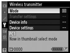
4 Select [Thumbnail select mode] for the [Wireless transmitter] > [Mode] option in the camera setup menu (pg. 152).
5 A list of available connection profiles will be displayed. Highlight the desired profile and press
Viewing Profile Information Press the camera Om (?) button to view information on the selected profile.
6 Turn on the WT-4.
7 Confirm that the selected profile is displayed in green in the top level of the wireless transmitter menu. For information on what to do if an error is displayed, see "Troubleshooting" (pg. 178).

Ad-hoc Networks (Windows Vista)
To connect to an ad-hoc network using Windows Vista, turn the WT-4 on and follow the steps below on the computer.
1 Click the "Start" orb and select [Connect To].
![NIKON WT-4 - Click the "Start" orb and select [Connect To]. - 1](/content/2025/01/116040/images/88467184449850196efa5e56613879ad27c3af96481b524265f124f5abbc397a.jpg)
2 Select the network name (SSID) for the WT-4 and click [Connect].
![NIKON WT-4 - Select the network name (SSID) for the WT-4 and click [Connect]. - 1](/content/2025/01/116040/images/0b4f73cff8ff287ca30f23a644d4d525615a23b1d946859e14e0785251e1a0c6.jpg)
3 Enter the network security key and click [Connect].
![NIKON WT-4 - Enter the network security key and click [Connect]. - 1](/content/2025/01/116040/images/c84a78c3f9cf674e0a85075fb618f01770f1674e26cd5185299e5ae8d85843e8.jpg)
4 Click [Close].
![NIKON WT-4 - Click [Close]. - 1](/content/2025/01/116040/images/f8cf18c5c55d53657dbab4426c315270ed46c3d077f10f73a281a101a17f0a0e.jpg)
Uploading Images
1 Connect the WT-4 as described above and select [Thumbnail select mode] for [Wireless transmitter] > [Mode]. Thumbnail Selector will start automatically.
2 Choose a camera in the [Source] panel. Small previews of the pictures on the WT-4 will appear in the thumbnail area.
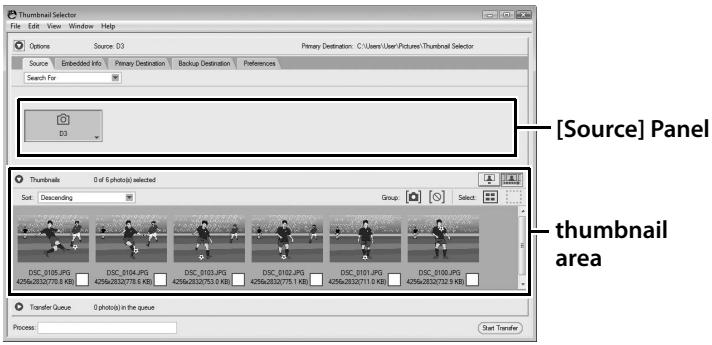
Starting Thumbnail Selector
To start Thumbnail Selector manually:
- Windows: Double-click the [Thumbnail Selector] shortcut on the desktop or display the Start menu and select [Thumbnail Selector] from the program list.
- Macintosh: Click the [Thumbnail Selector] icon in the Dock (if available) or open the "Applications/Nikon Software/Thumbnail Selector" folder and double-click the [Thumbnail Selector] icon.
The Camera Clock
At default settings, the computer and camera clocks will be synchronized then the host computer detects the camera. To prevent the camera clock from being reset, open the [Preferences] panel and remove the check from [Synchronize camera date and time to computer when camera is connected (supported cameras only)].
3 Right click the camera icon in the [Source] panel and select [Edit camera information]. Enter a name and choose a label for the camera and then click [OK]. The selected label will be displayed on the images in the thumbnail list.
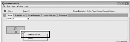
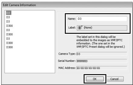
4 Take photographs. The new pictures will be displayed in the thumbnail list.
5 Click [Start Transfer]. The button will change to [Stop Transfer].
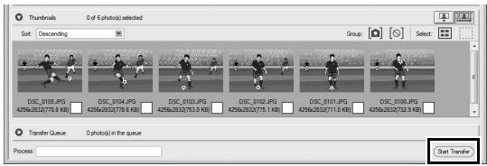
6 Click the thumbnail for a photograph that you wish to transfer to the computer. The selected thumbnail will be highlighted.
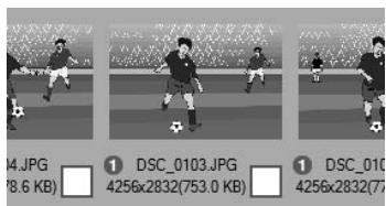


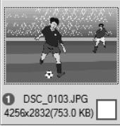
Click the selected thumbnail again or press the spacebar. A check-mark will appear on the selected photograph and upload will begin immediately.


At default settings, photographs are uploaded to a "WT-4" folder in the "Picture" (Windows Vista/Mac OS X) or "My Pictures" (Windows XP) folder. For more information on using Thumbnail Selector, see online help.
7 Turn the WT-4 off when transfer is complete. Wait for the POWER LED (pg. 3) to turn from green to yellow and then go out, and then disconnect the USB cable.
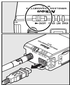
Network Status
The status of the link between the host and the WT-4 is shown by the status LEDs and by the display in the top level of the wireless transmitter menu.
The Status LEDs
The POWER LED lights when the WT-4 is on. Signal quality is shown by the LINK LED: the faster the LED blinks, the better the signal and the faster data can be transmitted. The ERROR LED blinks to show that an error has occurred.
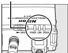
Status LEDs
| Status | POWER | LINK | ERROR |
| WT-4 off | ● (off) | ● (off) | ● (off) |
| USB cable not connected | ○ (on) | ● (off) | ● (off) |
| Connecting to host | ○ (on) | ○ (on) | ● (off) |
| Waiting to send or sending data | ○ (on) | (blinks) | ● (off) |
| Connection error | (blinks) | ● (off) | (blinks) |
| WT-4 hardware or battery malfunction | (blinks) | (blinks) | (blinks) |
The Status Display
Network status can also be viewed in the top level of the wireless transmitter menu.
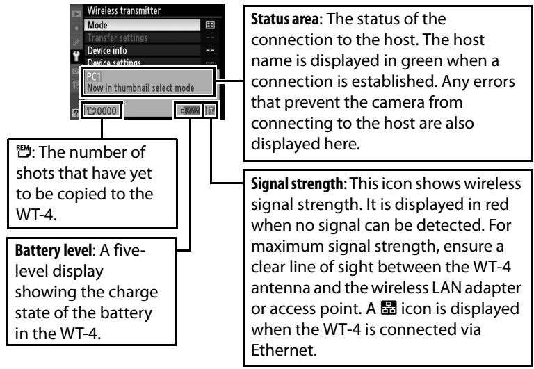
PC Mode
In PC mode, a camera equipped with a WT-4 can be controlled over a wireless or Ethernet network from a computer running Camera Control Pro 2 (available separately) and photographs saved directly to the computer hard disk instead of the camera memory card.
Connecting to the Computer
Before connecting the WT-4, select [MTP/PTP] for the [USB] option in the camera setup menu (pg. 7) and confirm that the host computer is running.
1 Turn the camera off.
To access the network via Ethernet, connect the Ethernet cable (pg. 2). Note that wireless transfer is disabled while an Ethernet cable is connected. Disconnect the Ethernet cable before accessing a wireless network. Turn the WT-4 off before connecting or disconnecting the Ethernet cable.
2 Open the WT-4 USB connector cover and connect the USB cable from the WT-4 to the camera USB connector.
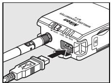
3 Turn the camera on.
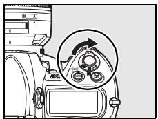
4 Select [PC mode] for the [Wireless transmitter] > [Mode] option in the camera setup menu (pg. 152).
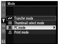
5 A list of available connection profiles will be displayed. Highlight the desired profile and press © .
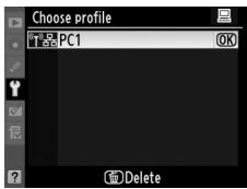
Viewing Profile Information Press the camera Otn (? button to view information on the selected profile.
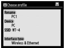
6 Turn on the WT-4.
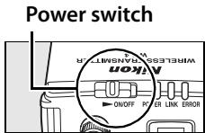
The message "Now in PC mode" will be displayed in the top level of the wireless transmitter menu when a connection is established. For information on what to do if an error is displayed, see "Troubleshooting" (pg. 178).
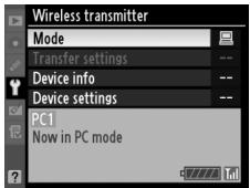
Ad-hoc Networks (Windows Vista)
To connect to an ad-hoc network using Windows Vista, turn the WT-4 on and follow the steps below on the computer.
1 Click the "Start" orb and select [Connect To].
![NIKON WT-4 - Click the "Start" orb and select [Connect To]. - 1](/content/2025/01/116040/images/e8ef4b62556fb0e9cdab0449312753664f0a30ca3ec8dc5ff7cea0189c407b87.jpg)
2 Select the network name (SSID) for the WT-4 and click [Connect].
![NIKON WT-4 - Select the network name (SSID) for the WT-4 and click [Connect]. - 1](/content/2025/01/116040/images/31122f6d98ab6aef572be018984337b636bc7ee3f9f3bccbb4ad1fa9da601766.jpg)
3 Enter the network security key and click [Connect].
![NIKON WT-4 - Enter the network security key and click [Connect]. - 1](/content/2025/01/116040/images/a6f3a4f6f635c8ca146358b85397ad4a92a3c1dde8fe0b08ded70821cc9e37ad.jpg)
4 Click [Close].
![NIKON WT-4 - Click [Close]. - 1](/content/2025/01/116040/images/230cbc2943c64617cda96f66c52271f4a14a334deba1e0ced9868b14e17a90f4.jpg)
Controlling the Camera
1 Complete the steps in "Connecting to the Computer" (pp. 90-93).
2 Start Camera Control Pro 2 on the host computer and confirm that "PC" is displayed in the camera control panel.
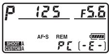
3 Control the camera as described in the Camera Control Pro 2 manual. Any photographs taken while the camera is connected will be recorded directly to the computer hard disk.
4 Turn the WT-4 off when transfer is complete. Wait for the POWER LED (pg. 3) to turn from green to yellow and then go out, and then disconnect the USB cable.
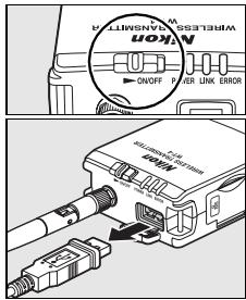
V Wireless Networks
More time may be required to complete operations on wireless networks.
V Ethernet Networks: Do Not Disconnect the Ethernet Cable
Do not disconnect the Ethernet cable while the camera is on.
Wireless Networks: Loss of Signal During Transfer
A loss of signal may interrupt the connection while pictures are being transferred to Camera Control Pro 2. If the POWER LED on the WT-4 is blinking (pg. 2), turn the WT-4 off and then on again. Transfer will resume when the connection is re-established. Do not turn the camera off. Transfer can not be resumed once the camera has been turned off.
Network Status
The status of the link between the host and the WT-4 is shown by the status LEDs and by the display in the top level of the wireless transmitter menu.
The Status LEDs
The POWER LED lights when the WT-4 is on. Signal quality is shown by the LINK LED: the faster the LED blinks, the better the signal and the faster data can be transmitted. The ERROR LED blinks to show that an error has occurred.

Status LEDs
| Status | POWER | LINK | ERROR |
| WT-4 off | ● (off) | ● (off) | ● (off) |
| USB cable not connected | ○ (on) | ● (off) | ● (off) |
| Connecting to host | ○ (on) | ○ (on) | ● (off) |
| Waiting to send or sending data | ○ (on) | (blinks) | ● (off) |
| Connection error | (blinks) | ● (off) | (blinks) |
| WT-4 hardware or battery malfunction | (blinks) | (blinks) | (blinks) |
The Status Display
Network status can also be viewed in the top level of the wireless transmitter menu.
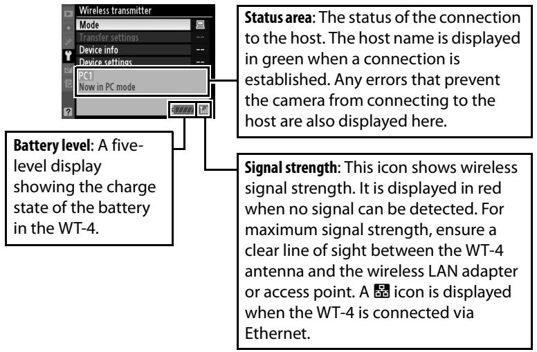
Print Mode
Select print mode to use the WT-4 to print JPEG images on a printer connected to a computer on the same network. Normally, pictures will be printed on the device selected as the default printer for the current host. To choose a different printer, follow the steps below (there is no need to connect the camera to the host via USB when choosing a printer). Print quality, page size, and other settings for the selected printer can be adjusted in the Windows printer setup dialog (Windows) or as described in Step 4 (Macintosh).
Configuring the Printer
1 Turn the computer on and start the WT-4 Setup Utility.
- Windows: Double-click the [WT-4 Setup Utility] icon on the desktop.
- Macintosh: Click the [WT-4WirelessSetup] icon in the Dock.
2 The dialog shown below will be displayed; click [Next].
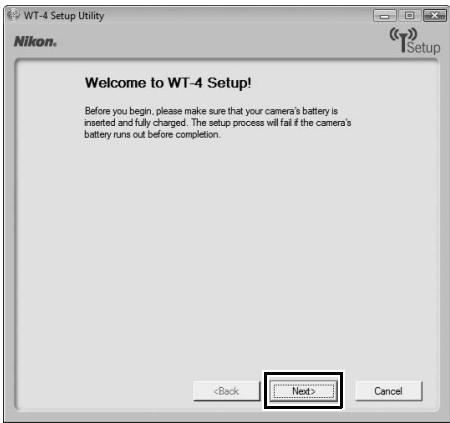
3 Select [Setup wireless printer] and click [Next].
![NIKON WT-4 - Select [Setup wireless printer] and click [Next]. - 1](/content/2025/01/116040/images/fb35478797379e1c12c2ea350c7669bfc5d04832101d0740201e82e1cfd9ab4f.jpg)
4 Choose a printer and click [Next].
- Windows: Select a printer from the pull-down menu.
![NIKON WT-4 - Choose a printer and click [Next]. - 1](/content/2025/01/116040/images/5e34345ec726beb3f063211121bccf3749619ecbe57ad67a23daa28d13746dff.jpg)
- Macintosh: Click [Select Printer...].
![NIKON WT-4 - Choose a printer and click [Next]. - 2](/content/2025/01/116040/images/3d72dd04c940ddbfb355fb4537cff6de2f251659acfe6941f63a7f8fa35e16dd.jpg)
The following dialog will be displayed; choose a printer and adjust printer settings. Click [Print] to return to the WT-4 setup utility.
![NIKON WT-4 - Choose a printer and click [Next]. - 3](/content/2025/01/116040/images/a28f29972d9dc79edc0912e7d9919df5989d073a282e67358c59d86adf713316.jpg)
5 Select [Finish wizard] and click [Next].
![NIKON WT-4 - Select [Finish wizard] and click [Next]. - 1](/content/2025/01/116040/images/3bca335b14e7e5589430f92080d4798018aaf721346c907d84b6f5396fc917df.jpg)
Printer setup is now complete.
Printing Pictures
Before connecting the WT-4, select [MTP/PTP] for the [USB] option in the camera setup menu (pg. 7) and confirm that the host computer is running and that the printer is on.
1 Turn the camera off and insert the memory card containing the pictures to be sent (if the camera is equipped with multiple memory card slots, the card can be inserted into any slot).

Front
To access the network via Ethernet, connect the Ethernet cable (pg. 2). Note that wireless transfer is disabled while an Ethernet cable is connected. Disconnect the Ethernet cable before accessing a wireless network. Turn the WT-4 off before connecting or disconnecting the Ethernet cable.
2 Open the WT-4 USB connector cover and connect the USB cable from the WT-4 to the camera USB connector.
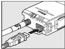
3 Turn the camera on.
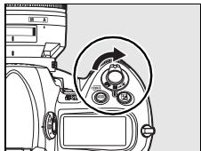
4 Select [Print mode] for the [Wireless transmitter] > [Mode] option in the camera setup menu (pg. 152).
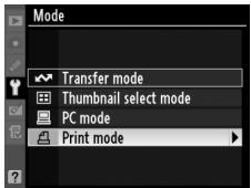
5 A list of available printer profiles will be displayed. Highlight the desired profile, then press to select and return to the top level of the wireless transmitter menu.

Viewing Profile Information
Press the camera o-m (?) button to view information on the selected profile.
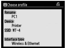
6 Turn on the WT-4.
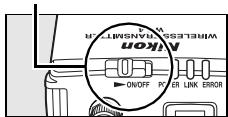
Power switch
7 Select [Print] in the top level of the [Wireless Transmitter] menu to connect to the printer. The status LEDs will light as a connection is negotiated with the printer.
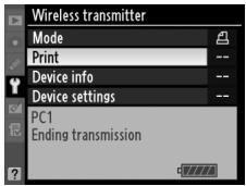
8 Print photographs from the [Print] menu as described in the camera manual. To exit the [Print] menu and return to the top level of the [Wireless Transmitter] menu, press .
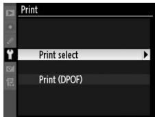
9 Turn the WT-4 off and wait for the POWER LED (pg. 3) to turn from green to yellow and then go out. Disconnect the USB cable.

Print Mode
The following restrictions apply to the WT-4 print mode option:
- NEF (RAW) and TIFF images can not be printed. To print images in these formats, transfer them to the computer and use ViewNX (supplied) or optional software packages such as Capture NX.
- Index print is not available.
- Images will not be played back in the camera monitor when the 回 button is pressed.
The Status LEDs
The POWER LED lights when the WT-4 is on. Signal quality is shown by the LINK LED: the faster the LED blinks, the better the signal and the faster data can be transmitted. The ERROR LED blinks to show that an error has occurred.
| Status | POWER | LINK | ERROR |
| WT-4 off | ● (off) | ● (off) | ● (off) |
| Connected to printer; pictures can be printed | ○ (on) | (blinks) | ● (off) |
| Error connecting to printer | ○ (on) | ● (off) | (blinks) |
| WT-4 hardware or battery malfunction | (blinks) | (blinks) | (blinks) |

Ad-hoc Networks (Windows Vista)
To connect to an ad-hoc network using Windows Vista, turn the WT-4 on and follow the steps below on the computer.
1 Click the "Start" orb and select [Connect To].
![NIKON WT-4 - Click the "Start" orb and select [Connect To]. - 1](/content/2025/01/116040/images/bbb9d19f9b9e590a73ce1ca6b44e5fde1a0c7a559c749cbd8e8bf7071cadbe46.jpg)
2 Select the network name (SSID) for the WT-4 and click [Connect].
![NIKON WT-4 - Select the network name (SSID) for the WT-4 and click [Connect]. - 1](/content/2025/01/116040/images/5a16e92140d1bd68c914cb790647aa3dbb21c274f0d3c64a1f2d2092e02a0091.jpg)
3 Enter the network security key and click [Connect].
![NIKON WT-4 - Enter the network security key and click [Connect]. - 1](/content/2025/01/116040/images/17f1457a9c076782d7725a3b61c67ebc7eabced7ed4ef41779f9eab85bbb6506.jpg)
4 Click [Close].
![NIKON WT-4 - Click [Close]. - 1](/content/2025/01/116040/images/69162a1f8462fd5bc50d847cfc74830cb93a78c3cac14e15023e7a0ac437c59c.jpg)
Uploading Images to an ftp Server
Follow the steps below to upload pictures to an ftp server over wireless or Ethernet networks.
1 Creating an ftp Server (pg. 108)
-Windows Vista (pg. 108)
- Windows XP (pg. 114)
Macintosh (pg. 117)
2 Copying Network Profiles to the Camera (pg. 119)
-Ad Hoc Networks (pg. 119)
Infrastructure Networks (pg. 129)
3 Connecting to the ftp Server (pg. 140)
4 Uploading Images (pg. 145)
Creating an ftp Server
The WT-4 can be used to upload pictures to ftp servers created using standard ftp services included with Windows Vista (32-bit Ultimate/Business/Enterprise editions), Windows XP Professional (Service Pack 1 or later), and Mac OS X (version 10.3.9 or version 10.4.10). Under Windows, Internet Information Services (IIS) are required to configure ftp servers (IIS is included in the standard install of Windows Vista Ultimate, Windows Vista Business, Windows Vista Enterprise, and Windows XP Professional; for information, contact Microsoft). Mac OS X versions 10.3.9 and 10.4.10 also support ftp services. Be sure to use characters supported by the WT-4 (pg. 153) when specifying such settings as user ID, password, and folder names.
Windows Vista
1 Open the [Network and Internet] > [Network and Sharing Center] control panel.
2 Select [Manage network connections].
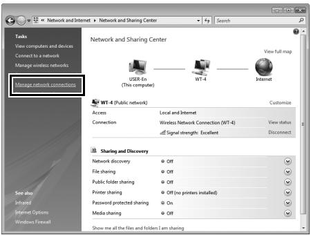
3 Right-click the [Wireless Network Connection] icon and select [Properties] from the menu that appears.
![NIKON WT-4 - Right-click the [Wireless Network Connection] icon and select [Properties] from the menu that appears. - 1](/content/2025/01/116040/images/d629c4def7265a15dc20d773c30c2b56aac38f613c17719aa4dd077c280892a2.jpg)
4 A "User Account Control" dialog will be displayed; click [Allow].
5 Select [Internet Protocol Version 4 (TCP/IPv4)] and click [Properties].
![NIKON WT-4 - Select [Internet Protocol Version 4 (TCP/IPv4)] and click [Properties]. - 1](/content/2025/01/116040/images/dd7cdfdd18b2de4474865ec4736db12c55d8de4a7ec8272d56206d77ceba9fbf.jpg)
6 Enter an IP address and sub-net mask for the ftp server and click [OK].
![NIKON WT-4 - Enter an IP address and sub-net mask for the ftp server and click [OK]. - 1](/content/2025/01/116040/images/b047507b338af501f21cd3e06acfac55cd7eda3db8e1c9145cf30b92134d5e96.jpg)
7 Go to the [System and Maintenance] > [Administrative Tools] control panel.
8 Double-click [IIS6 Manager].
![NIKON WT-4 - Double-click [IIS6 Manager]. - 1](/content/2025/01/116040/images/757b69b22a975815f68b3f35888e14ee94eb35993d223f19730d9c7c757d47d9.jpg)
9 A "User Account Control" dialog will be displayed; click [Allow].
10 Right-click [Default FTP Site] and select [Properties] from the menu that appears.
![NIKON WT-4 - Right-click [Default FTP Site] and select [Properties] from the menu that appears. - 1](/content/2025/01/116040/images/47af236c356ec85bb9328d32d909f324fb977be134918927161188294524598c.jpg)
11 Select the IP address entered in Step 6 and enter a [TCP port] number. The port number is normally 21.
![NIKON WT-4 - Select the IP address entered in Step 6 and enter a [TCP port] number. The port number is normally 21. - 1](/content/2025/01/116040/images/d9f0ef22647c66622f23f6b5cb77f61dc29f98624863d4d7f1dbfc09e8abc537.jpg)
12 Open the [Home Directory] tab and select [A directory located on this computer]. The root directory for images uploaded to the ftp server is listed in the [Local path] text box; choose a folder and select [Read], [Write], and [Log visits]. Click [OK] to close the properties dialog.
![NIKON WT-4 - Select the IP address entered in Step 6 and enter a [TCP port] number. The port number is normally 21. - 2](/content/2025/01/116040/images/e5fe63ebc8a4f8a49b6885849b175b1c233c140f82b2582b400fd765ffaeec44.jpg)
This completes ftp server setup. Proceed to "Copying Network Profiles to the Camera" (pg. 119).
1 Open the [Control Panel] > [Network and Internet Settings] > [Network Connections] control panel.
2 Right-click the [Wireless Network Connection] icon and select [Properties] from the menu that appears.
![NIKON WT-4 - Select the IP address entered in Step 6 and enter a [TCP port] number. The port number is normally 21. - 3](/content/2025/01/116040/images/cc16286b79f9f483481efbdcf6f5a90bcdb9fe34a8926301f8de0a0ac5b47f60.jpg)
3 Select [Internet Protocol (TCP/IP)] and click [Properties].
![NIKON WT-4 - Select the IP address entered in Step 6 and enter a [TCP port] number. The port number is normally 21. - 4](/content/2025/01/116040/images/b9b099cc19360d90b6d74f5863cce14152ee3db74eece22961fcd649b6a800c6.jpg)
4 Enter an IP address and sub-net mask for the ftp server and click [OK].
![NIKON WT-4 - Enter an IP address and sub-net mask for the ftp server and click [OK]. - 1](/content/2025/01/116040/images/2a6bff572dd23207ed2baf0a7fa20e336800807bdce9b88ccef1d4fe9a7bb9ef.jpg)
5 Go to the [System and Maintenance] > [Administrative Tools] control panel and open the [Internet Information Services] console.
![NIKON WT-4 - Go to the [System and Maintenance] > [Administrative Tools] control panel and open the [Internet Information Services] console. - 1](/content/2025/01/116040/images/4764a6c3dae5deb048d410cdf24fa8c8509b63c1ae8afcb4381e5a4516ed9923.jpg)
6 Right-click [Default FTP Site] and select [Properties] from the menu that appears.
![NIKON WT-4 - Right-click [Default FTP Site] and select [Properties] from the menu that appears. - 1](/content/2025/01/116040/images/408fafa102894627259c177c5f1ba61f9c5892314d0176b2f7a924950048b392.jpg)
7 Select the IP address entered in Step 4 and enter a [TCP Port] number. The port number is normally 21.
![NIKON WT-4 - Select the IP address entered in Step 4 and enter a [TCP Port] number. The port number is normally 21. - 1](/content/2025/01/116040/images/5048804a6381662bf64d3af8e7ba54f72b3d3844cd3c39535a291e14f869c88d.jpg)
8 Open the [Home Directory] tab and select [a directory located on this computer]. The root directory for images uploaded to the ftp server is listed in the [Local Path] text box; choose a folder and select [Read], [Write], and [Log visits]. Click [OK] to close the properties dialog.
![NIKON WT-4 - Open the [Home Directory] tab and select [a directory located on this computer]. The root directory for images uploaded to the ftp server is listed in the [Local Path] text box; choose a folder and select [Read], [Write], and [Log visits]. Click [OK] to close the properties dialog. - 1](/content/2025/01/116040/images/ee4d9291276e8181f026e805b8817bb7c2cbe0b61d189abedfd29f8e981f813b.jpg)
This completes ftp server setup. Proceed to "Copying Network Profiles to the Camera" (pg. 119).
1 Open [System Preferences] and click [Network].
![NIKON WT-4 - Open the [Home Directory] tab and select [a directory located on this computer]. The root directory for images uploaded to the ftp server is listed in the [Local Path] text box; choose a folder and select [Read], [Write], and [Log visits]. Click [OK] to close the properties dialog. - 2](/content/2025/01/116040/images/2e705ff7064a1abd077e34c84bb84e6503d575a33e3ccfdda7ae18d14421235e.jpg)
2 Select [AirPort] from the [Show] menu.
![NIKON WT-4 - Open the [Home Directory] tab and select [a directory located on this computer]. The root directory for images uploaded to the ftp server is listed in the [Local Path] text box; choose a folder and select [Read], [Write], and [Log visits]. Click [OK] to close the properties dialog. - 3](/content/2025/01/116040/images/7047b6a14a38d790460a73aa7757913f9dc3e1d3ad56ae08196afa22ff34e300.jpg)
3 Select [Manually] from the [Configure IPv4] menu and enter an IP address and sub-net mask.
![NIKON WT-4 - Open the [Home Directory] tab and select [a directory located on this computer]. The root directory for images uploaded to the ftp server is listed in the [Local Path] text box; choose a folder and select [Read], [Write], and [Log visits]. Click [OK] to close the properties dialog. - 4](/content/2025/01/116040/images/1e6dff3a2f5d461fdeeae05f5a43a390a9024e2a5762a9b8a5045312f986cb07.jpg)
Make a note of this address. It will be needed to set up the WT-4.
4 Click [Show All] to return to the System Preferences dialog.
![NIKON WT-4 - Click [Show All] to return to the System Preferences dialog. - 1](/content/2025/01/116040/images/60429af0a2d177c2b5bd1524ba1351e51bae9c00e2f4757b987e0108b163cc8a.jpg)
5 Click [Sharing].
![NIKON WT-4 - Click [Sharing]. - 1](/content/2025/01/116040/images/bab8c860226ec99686430218612f6ba7ce523d62c813adc4152b191e097ca75d.jpg)
6 Select [Services] and enable [FTP Access].
![NIKON WT-4 - Select [Services] and enable [FTP Access]. - 1](/content/2025/01/116040/images/81119dd94ebe6bd52211c4505629b24b9c212c6da480e45650e4209f21c39774.jpg)
This completes ftp server setup. Proceed to "Copying Network Profiles to the Camera" (pg. 119).
Copying Network Profiles to the Camera
Ad Hoc Networks
1 Connect the UC-E4 as shown below.
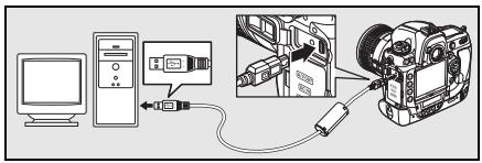
2 Turn the camera on.
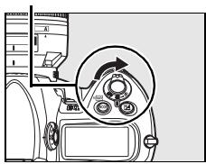
Power switch
3 Turn the computer on and start the WT-4 Setup Utility.
- Windows: Double-click the [WT-4 Setup Utility] icon on the desktop.
- Macintosh: Click the [WT-4WirelessSetup] icon in the Dock.
4 The dialog shown below will be displayed; click [Next].
![NIKON WT-4 - The dialog shown below will be displayed; click [Next]. - 1](/content/2025/01/116040/images/852ae18c65866044130338ec07b7a544f2a37c40d2503ae02fc9498319cf5add.jpg)
5 Select [Add/Edit profiles] and click [Next].
![NIKON WT-4 - Select [Add/Edit profiles] and click [Next]. - 1](/content/2025/01/116040/images/5bd63c0c22b93c2c3a7ad17d46d3e3d049a2cd4d1ebdf63d25815c1ff64309d2.jpg)
6 Select [Add new profile] and click [Next].
![NIKON WT-4 - Select [Add new profile] and click [Next]. - 1](/content/2025/01/116040/images/ef8689283f9e4829d671e829fd20ee28ef6fc6bdea87d1200f966c8b4b0a2c31.jpg)
7 Enter the following information and click [Next]:
- Profile name: Enter a name of up to 16 characters.
- Profile type: Choose [FTP Server].
- Interface type: Choose [Wireless & Ethernet] for networks that include wireless, or [Ethernet only] for Ethernet-only networks.
![NIKON WT-4 - Enter the following information and click [Next]: - 1](/content/2025/01/116040/images/05b4c0a09b10b280f8fd443c64f59c0a749011d5d9165273441dd1ee60867188.jpg)
8 Select [Manual setup] and click [Next].
![NIKON WT-4 - Select [Manual setup] and click [Next]. - 1](/content/2025/01/116040/images/1780564b0eef7265052652702520ad8c6bca63c0b54318c6ee9708438ca55151.jpg)
9
Enter the following information and click [Next].
- Network name (SSID): Enter a network name or choose from a list of existing networks. Do not change the name if it is supplied automatically.
- Communication mode: Select [Ad hoc].
- Channel: Select a channel. Note that if a matching SSID is detected on a different channel, the WT-4 may change the channel automatically.
- Authentication: Choose the type of authentication used on the network. In ad-hoc mode, the camera supports open system and shared key authentication.
- Encryption: The type of encryption used on the network. Choose from [None] (open networks only), 64-bit WEP, and 128-bit WEP.
- Encryption key: If the network uses encryption, enter the network key. The number of characters required depends on the type of key used:
| WEP (64-bit) | WEP (128-bit) | |
| Number of characters (ASCII) | 5 | 13 |
| Number of characters (hex) | 10 | 26 |
- Key Index: If [WEP64] or [WEP128] is selected for [Encryption], choose a key index (the default index is [1]). A key index is not required when [None] is selected.
![NIKON WT-4 - Select [Manual setup] and click [Next]. - 2](/content/2025/01/116040/images/d23df5fda00649c62b19b5ac45842ac6d4dc6f4bb58f03ef15eb297f94064294.jpg)
Enter the following information and click [Next].
- Obtain IP address automatically: Select this option if the network is configured to supply IP addresses automatically. If the network does not include a DHCP server, addresses will be supplied by Auto IP (pg. 180).
- IP address: If the network is configured for manual IP addressing, enter an IP address for the WT-4.
- Subnet mask: If the network is configured for manual IP addressing, enter a subnet mask for the WT-4.
- Default gateway: If the network requires a gateway address, select this option and enter the address supplied by the network administrator. This option applies only if [FTP Server] is selected for [Profile type] in Step 7.
- DNS Server: If a Domain Name Server exists on the network, select this option and enter the address supplied by the network administrator. This option applies only if [FTP Server] is selected for [Profile type] in Step 7.
![NIKON WT-4 - Select [Manual setup] and click [Next]. - 3](/content/2025/01/116040/images/19241bd919c15eac26162497b2e75f4b8894f94e1d8897ecbdb9b959da2f34e6.jpg)
11 Enter ftp settings and click [Next].
- FTP server: Enter the URL or IP address of the ftp server.
- FTP server port: Enter the port number for the ftp server. The default port is 21.
- FTP path: Choose the folder to which pictures will be uploaded. If no path is specified, pictures will be uploaded to the folder specified in Step 12 of "Creating an ftp Server: Windows Vista" (Windows Vista) or Step 8 of "Creating an ftp Server: Windows XP" (Windows XP) or to the home folder for the current user (Mac OS X).
- Anonymous login: Select this option for anonymous login, or leave this option unchecked to supply a [UserID] and [Password].
- Use proxy server: If a proxy server is required for ftp, select this option and enter the server name and port number for the proxy server.
- PASV mode: Select this option to use PASV mode.
![NIKON WT-4 - Enter ftp settings and click [Next]. - 1](/content/2025/01/116040/images/7161bd93e5b4cac31345acce044ed36f887f859bb755a2b161df4579601afd2f.jpg)
12 Confirm that settings are correct and click [Next].
![NIKON WT-4 - Confirm that settings are correct and click [Next]. - 1](/content/2025/01/116040/images/ebe8545dedfa7d791a6881b91b5479e5a3c7ee75803279430a18ad2fd197d034.jpg)
13 Select [Finish wizard] and click [Next].
![NIKON WT-4 - Select [Finish wizard] and click [Next]. - 1](/content/2025/01/116040/images/d4fbbfa7459d9584ae879b46b73aff151ee853aa5aaab36b07397712d926ff56.jpg)
14 Turn the camera off and disconnect the USB cable.
![NIKON WT-4 - Select [Finish wizard] and click [Next]. - 2](/content/2025/01/116040/images/2de9f0fdb92b9ca6d6bc032c199929384ca182113c6ab800421d2ea98b64a0bc.jpg)
![NIKON WT-4 - Select [Finish wizard] and click [Next]. - 3](/content/2025/01/116040/images/2fb47a0180e9ea058698d89b881c2a52a2ec3e12a8186a7051da37e6f0e7b142.jpg)
The network profile has now been copied to the camera. Proceed to "Connecting to the ftp Server" (pg. 140).
1 Connect the UC-E4 as shown below.

2 Turn the camera on.
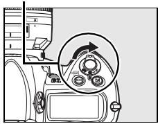
Power switch
3 Turn the computer on and start the WT-4 Setup Utility.
- Windows: Double-click the [WT-4 Setup Utility] icon on the desktop.
- Macintosh: Click the [WT-4WirelessSetup] icon in the Dock.
4 The dialog shown below will be displayed; click [Next].
![NIKON WT-4 - The dialog shown below will be displayed; click [Next]. - 1](/content/2025/01/116040/images/6e58989dc6f805a67b1029e741e7f0a1c352a31f7ff92347f726272c11f0afa3.jpg)
5 Select [Add/Edit profile] and click [Next].
![NIKON WT-4 - Select [Add/Edit profile] and click [Next]. - 1](/content/2025/01/116040/images/7a67039dfe86b7b12d5d6ba2b4ce86cd1c9a0795c509cb67527ebb75d8ef6ac3.jpg)
6 Select [Add new profile] and click [Next].
![NIKON WT-4 - Select [Add new profile] and click [Next]. - 1](/content/2025/01/116040/images/71034e3d57163df975fc2e5e265cae1af36d906a05d6c555899d3d531a047b13.jpg)
7 Enter the following information and click [Next]:
- Profile name: Enter a name of up to 16 characters.
- Profile type: Choose [FTP Server].
- Interface type: Choose [Wireless & Ethernet] for networks that include wireless, or [Ethernet only] for Ethernet-only networks.
![NIKON WT-4 - Enter the following information and click [Next]: - 1](/content/2025/01/116040/images/e6fdbc35ac9e959380766ec48cfc68f340114eca17c0c052d9bed9b42ff676e2.jpg)
8 Select [Manual setup] and click [Next].
![NIKON WT-4 - Select [Manual setup] and click [Next]. - 1](/content/2025/01/116040/images/f90df3b7a5d4d8ebd3f250f508dd9137ef5dd5a04e6f24569608d9248dfcc465.jpg)
![NIKON WT-4 - Select [Manual setup] and click [Next]. - 2](/content/2025/01/116040/images/725739c077e629a4e40a7def5de86438b1680b4faf6591307e5e2908d0e88193.jpg)
"Automatic Setup"
Choose [Automatic setup (recommended)] when using a new network for the first time. The following dialog will be displayed. Select [Infrastructure network (recommended)] (if more than one infrastructure network exists, choose a network from the pull-down menu) and click [Next] to proceed to Step 11 (pg. 137).
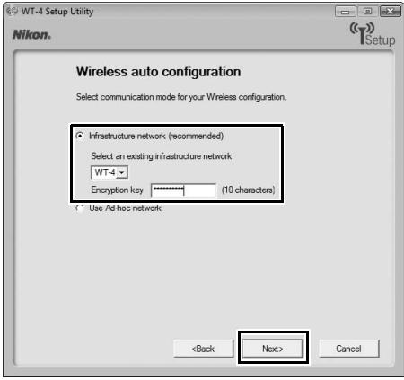
The [Automatic setup (recommended)] option can not be used with existing network profiles, third-party wireless LAN adapters, networks using static IP addresses, Windows XP SP1, Mac OS X, or computers that are not configured for connection to a wireless LAN access point.
9
Enter the following information and click [Next].
- Network name (SSID): Enter a network name or choose from a list of existing networks. Do not change the name if it is supplied automatically.
- Communication mode: Select [Infrastructure].
- Authentication: Choose the authentication used on the network. In infrastructure mode, the camera supports WPA-PSK, WPA2-PSK, open system, and shared key authentication.
- Encryption: Choose the encryption used on the network. The options available depend on the authentication used:
Open: None, 64- or 128-bit WEP
Shared: 64- or 128-bit WEP
WPA-PSK: TKIP, AES
WPA2-PSK: AES
- Encryption key: If the network uses encryption, enter the network key. The number of characters required depends on the type of key used:
| WEP (64-bit) | WEP (128-bit) | TKIP, AES | |
| Number of characters (ASCII) | 5 | 13 | 8-63 |
| Number of characters (hex) | 10 | 26 | 64 |
- Key Index: If [WEP64] or [WEP128] is selected for [Encryption], choose a key index (the default index is [1]). A key index is not required when [None] is selected.
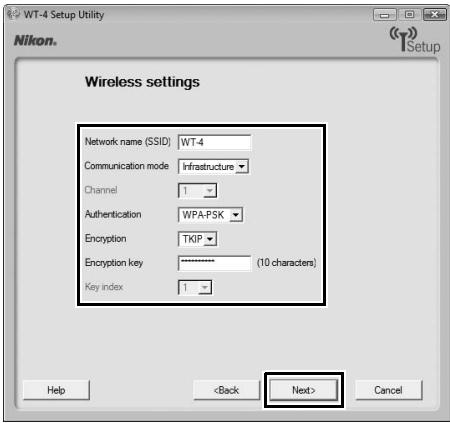
10 Enter the following information and click [Next].
- Obtain IP address automatically: Select this option if the network is configured to supply IP addresses automatically. If the network does not include a DHCP server, addresses will be supplied by Auto IP (pg. 180).
- IP address: If the network is configured for manual IP addressing, enter an IP address for the WT-4.
- Subnet mask: If the network is configured for manual IP addressing, enter a subnet mask for the WT-4.
- Default gateway: If the network requires a gateway address, select this option and enter the address supplied by the network administrator. This option applies only if [FTP Server] is selected for [Profile type] in Step 7.
- DNS Server: If a Domain Name Server exists on the network, select this option and enter the address supplied by the network administrator. This option applies only if [FTP Server] is selected for [Profile type] in Step 7.
![NIKON WT-4 - Enter the following information and click [Next]. - 1](/content/2025/01/116040/images/a168f896332663b5287738a842430601e1045f33fee489b53d7ea00f477f79d3.jpg)
11 Enter ftp settings and click [Next].
- FTP server: Enter the URL or IP address of the ftp server.
- FTP server port: Enter the port number for the ftp server. The default port is 21.
- FTP path: Choose the folder to which pictures will be uploaded. If no path is specified, pictures will be uploaded to the folder specified in Step 12 of "Creating an ftp Server: Windows Vista" (Windows Vista) or Step 8 of "Creating an ftp Server: Windows XP" (Windows XP) or to the home folder for the current user (Mac OS X).
- Anonymous login: Select this option for anonymous login, or leave this option unchecked to supply a [UserID] and [Password].
- Use proxy server: If a proxy server is required for ftp, select this option and enter the server name and port number for the proxy server.
- PASV mode: Select this option to use PASV mode.
![NIKON WT-4 - Enter ftp settings and click [Next]. - 1](/content/2025/01/116040/images/8e1be506de3038365350437f4370866213edb17f4c5138dd2f17fae8cbbc4201.jpg)
12 Confirm that settings are correct and click [Next].
![NIKON WT-4 - Confirm that settings are correct and click [Next]. - 1](/content/2025/01/116040/images/2e15fca9b90350939291381857131ec60fe23e51f41609460226bc82fbc29c46.jpg)
13 Select [Finish wizard] and click [Next].
![NIKON WT-4 - Select [Finish wizard] and click [Next]. - 1](/content/2025/01/116040/images/4ccadcc7f1d84984f6325269f17d2af8ddf844350faf1c0cedd0d70c972ecc5c.jpg)
14 Turn the camera off and disconnect the USB cable.
![NIKON WT-4 - Select [Finish wizard] and click [Next]. - 2](/content/2025/01/116040/images/788386cfef31a119ff03aac6b7b298b2c78e23de1149ffd58356f9a992ee5286.jpg)
![NIKON WT-4 - Select [Finish wizard] and click [Next]. - 3](/content/2025/01/116040/images/ae1e9e659a18b721d010a1a5b10c7d473255fb0ccb0729ac627ec05ac4eac6cd.jpg)
The network profile has now been copied to the camera. Proceed to "Connecting to the ftp Server" (pg. 140).
Connecting to the ftp Server
Before connecting the WT-4, select [MTP/PTP] for the [USB] option in the camera setup menu (pg. 7) and confirm that the host computer is running and the user is logged in.
1 Turn the camera off and insert the memory card containing the pictures to be sent (if the camera is equipped with multiple memory card slots, the card can be inserted into any slot).
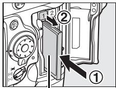
Front
To access the network via Ethernet, connect the Ethernet cable (pg. 2). Note that wireless transfer is disabled while an Ethernet cable is connected. Disconnect the Ethernet cable before accessing a wireless network. Turn the WT-4 off before connecting or disconnecting the Ethernet cable.
2 Open the WT-4 USB connector cover and connect the USB cable from the WT-4 to the camera USB connector.
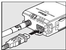
3 Turn the camera on.
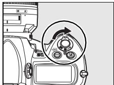
4 Select [Transfer mode] for the [Wireless transmitter] > [Mode] option in the camera setup menu (pg. 152).
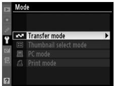
5 A list of available connection profiles will be displayed. Highlight the desired profile and press © .
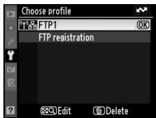
Viewing Profile Information
Press the camera O-m (?) button to view information on the selected profile.
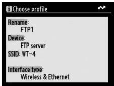
Editing ftp Server Profiles
To edit the ftp server profile, press the camera button after turning on the WT-4. See the Menu Guide for more information (pg. 153).
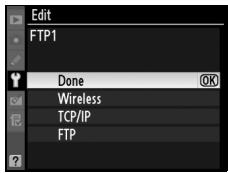
6 Select [Wireless transmitter] > [Transfer settings] and adjust settings as described on pages pp. 169-170.
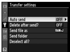
7 Turn on the WT-4.
Power switch

8 Confirm that the selected profile is displayed in green in the top level of the wireless transmitter menu. For information on what to do if an error is displayed, see "Troubleshooting" (pg. 178).
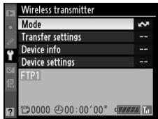
Ad-hoc Networks (Windows Vista)
To connect to an ad-hoc network using Windows Vista, turn the WT-4 on and follow the steps below on the computer.
1 Click the "Start" orb and select [Connect To].
![NIKON WT-4 - Click the "Start" orb and select [Connect To]. - 1](/content/2025/01/116040/images/dda85a8e10b4dd9713673a7ca1a7ffc9edf98f1eef03fa05bf1de976879a1e2a.jpg)
2 Select the network name (SSID) for the WT-4 and click [Connect].
![NIKON WT-4 - Select the network name (SSID) for the WT-4 and click [Connect]. - 1](/content/2025/01/116040/images/cbeb5fc719ca2e0971fc66bf03c685b3b0bc5b08147f92a14fe07e311cf1556a.jpg)
3 Enter the network security key and click [Connect].
![NIKON WT-4 - Enter the network security key and click [Connect]. - 1](/content/2025/01/116040/images/f3cc7ac6c55622204710311d10aec0d3d8adc95d038f6a1d57c0897eb8025ab6.jpg)
4 Click [Close].
![NIKON WT-4 - Click [Close]. - 1](/content/2025/01/116040/images/22c68b934afbccd357787a6c82ab371af28599d24b46fe23c7901b9a2f6f551e.jpg)
Uploading Images
1 Press the button to view pictures on the memory card. Display the first picture to be sent in single-image playback or highlight it in the thumbnail list.
2 While pressing the button, press the center of the multi selector (D3) or the button (D300). The image will be marked with a white "send" icon and transmission will begin immediately. During upload, images are marked with
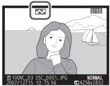
a green "sending" icon. Repeat this process to send additional images (pictures will be sent in the order selected).
Images that have been successfully uploaded are marked with a blue "sent" icon. Images can be resent by pressing the center of the multi selector while pressing the 3 button (D3) or the button (D300) to change the blue "sent" icon to a white "send" icon.

D300 Retouch Options
When [Wireless transmitter] > [Mode] > [Transfer mode] is selected in the camera setup menu and the WT-4 is on, the button on the D300 is used during playback to select pictures for upload, preventing it from being used to select pictures for other operations, such as side-by-side comparison. To restore normal operation, select another option for [Wireless transmitter] > [Mode].
3 Turn the WT-4 off and wait for the POWER LED (pg. 3) to turn from green to yellow and then go out, then disconnect the USB cable. The destination folder can be selected using the Setup Utility (pp. 50, 126).
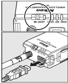
Interrupting Transmission
To cancel transmission of images marked with a white "send" icon or green "sending" icon, select the images during playback and press the center of the multi selector while pressing the l button (D3) or the l button (D300). The icon will be removed. Any of the following actions will also interrupt transmission:
- Turning the camera or WT-4 off
- Selecting [Yes] for [Wireless transmitter] > [Transfer settings] > [Deselect all?]
During Upload
Do not remove the memory card or disconnect the Ethernet cable during upload.
File Names
To prevent files from being overwritten during transfer, select [On] for the [File number sequence] option in the camera Custom Settings menu before shooting. When uploading files from multiple cameras to the same server, assign each camera its own folder.
Voice Memos
Voice memos can not be uploaded separately, but will be included when associated pictures are transmitted. Voice recordings can not be selected for upload.
Transfer Status
During playback, the status of images selected for uploaded is shown as follows:
: "Send"
Images that have been selected for upload are marked with a white icon.

: "Sending"
A green icon is displayed during upload.

图:“Sent”
Images that have been uploaded successfully are marked with a blue icon.

Loss of Signal
Transmission may be interrupted if the signal is lost (pg. 148).
Transmission can be resumed by turning the WT-4 off and then on again.
Turning the Camera Off
"Send" marking will be saved if the camera or WT-4 is turned off while transmission is in progress. Transmission of images marked with a "send" icon will resume when the camera or WT-4 is turned on.
Removing the "Send," "Sending," and "Sent" Icons
"Send," "sending," and "sent" icons can be removed from all images by selecting [Yes] for [Wireless transmitter] > [Transfer settings] > [Deselect all?] (pg. 170).
Network Status
The status of the link between the host and the WT-4 is shown by the status LEDs and by the display in the top level of the wireless transmitter menu.
The Status LEDs
The POWER LED lights when the WT-4 is on. Signal quality is shown by the LINK LED: the faster the LED blinks, the better the signal and the faster data can be transmitted. The ERROR LED blinks to show that an error has occurred.

Status LEDs
| Status | POWER | LINK | ERROR |
| WT-4 off | ● (off) | ● (off) | ● (off) |
| USB cable not connected | ○ (on) | ● (off) | ● (off) |
| Connecting to host | ○ (on) | ○ (on) | ● (off) |
| Waiting to send or sending data | ○ (on) | (blinks) | ● (off) |
| Connection error | (blinks) | ● (off) | (blinks) |
| WT-4 hardware or battery malfunction. | (blinks) | (blinks) | (blinks) |
The Status Display
Network status can also be viewed in the top level of the wireless transmitter menu.

Menu Guide
This section describes the settings available for the [Wireless transmitter] option in the camera setup menu when the WT-4 is connected.

| Menu item | Pg. |
| Mode | pg. 152 |
| Choose Profile | pg. 152 |
| FTP Registration (for Connection to ftp Servers Only) | pg. 153 |
| Editing ftp Profiles | pg. 153 |
| Transfer Settings (Transfer Mode Only) | pg. 169 |
| Auto Send | pg. 169 |
| Delete After Send? | pg. 169 |
| Send File As | pg. 170 |
| Send Folder | pg. 170 |
| Deselect All? | pg. 170 |
| Print (Print Mode Only) | pg. 171 |
| Device Info | pg. 172 |
| Battery Info | pg. 172 |
| MAC Address | pg. 172 |
| Firmware Version | pg. 172 |
| Device Settings | pg. 173 |
| Auto Power Off | pg. 173 |
| Format Transmitter's Memory | pg. 173 |
Mode
Choose from [Transfer mode] (pg. 70), [Thumbnail select mode] (pg. 79), [PC mode] (pg. 90), and [Print mode] (pg. 97). Selecting any of these options displays a profile list showing the connections available in the selected mode.
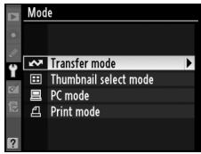
Choose Profile
Selecting an option from the [Mode] menu displays a profile list showing the connections available in the selected mode. The WT-4 can store a total of up to nine host, server, and printer profiles. To delete a profile, highlight it in the profile list and press
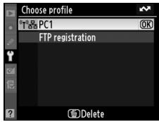
the 串 button. To edit an ftp server profile, highlight the profile and press the 串 button (pg. 153).
To view profile information, highlight the desired profile and press the On(?) button. The following information will be displayed.
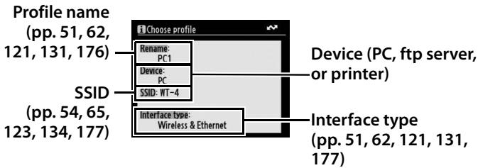
Using the Menus
If the shutter-release button on the camera is pressed while menus are displayed, the monitor will turn off and any changes to the current profile will be lost. Select [Monitor off delay] in the Custom Settings menu and choose a longer monitor off delay.
FTP Registration (for Connection to ftp
Servers Only)
In transfer mode, ftp profiles can be created without using the WT-4 Setup Utility. See the Appendix for more information (pg. 175). This option is only available when the WT-4 is connected to the camera via USB and the WT-4 is on.
Editing ftp Profiles
To edit an ftp server profile, highlight it in the profile list in transfer mode and press the button. Choose the settings to be edited from [Wireless], [TCP/IP], and [FTP], or select [Done] to save changes and return to the profile list. Only ftp server profiles can be

edited in this fashion; to edit other profiles, use the WT-4 Setup Utility. This option is only available when the WT-4 is connected to the camera via USB and the WT-4 is on.

Text Entry
The following dialog is displayed when text entry is required.
Keyboard area: Use multi selector to highlight letters, press center to select.
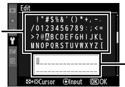
Text display area: Text appears in this area. To move cursor, press while using up, down, left, and right buttons on multi selector.
Use the multi selector to highlight the desired character in the keyboard area and press the center of the multi selector to insert the highlighted character at the current cursor position (note that if a character is entered when the field is full, the last character in the field will be deleted). To delete the character under the cursor, press the button. To move the cursor to a new position, press the button while using the multi selector.
To complete entry and return to the previous menu, press the 念 button. To exit to the previous menu without completing text entry, press MENU.
Wireless
This option contains settings for connection to a wireless network and is only displayed if the interface type for the selected profile is [Wireless & Ethernet]. The wireless menu has two pages of options; to scroll between pages, press the multi selector up or down.
Wireless Menu, Page 1/2
SSID: A BSS- or ESS-ID is required for connection to a wireless LAN adapter or access point. To change the BSS- or ESS-ID, highlight the current ID, press the multi selector to the right, and enter a new ID as described in the note on the previous page. Press @ to return to the wireless menu (1/2).
Communication mode: Choose a mode according to how the wireless network is set up.
| Option | Description |
| Infrastructure (default) | Connection to wireless network is via access point. |
| Ad-hoc | Direct peer-to-peer wireless connection to host. |
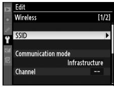
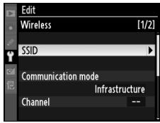
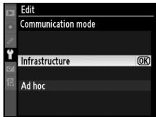
Ethernet Networks
No adjustments to wireless LAN settings are required when the camera is connected to a LAN by an Ethernet cable.
1 Choose channel.
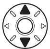
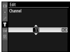
2 Return to wireless menu (1/2).

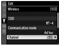
- Not required if [Infrastructure] is selected for [Communication mode].
Authentication: Choose the type of authentication used by the computer or access point. The camera supports WPA-PSK, WPA2-PSK, open system, and shared key authentication. WPA-PSK and WPA2-PSK are available only in infrastructure mode.
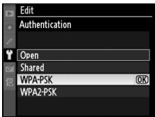
1 Highlight encryption method.

Encryption
The type of encryption available depends on the option selected for [Authentication] (pp. 54, 65, 155):
-Open: No encryption, WEP
- Shared: WEP
WPA-PSK: TKIP, AES
- WPA2-PSK: AES
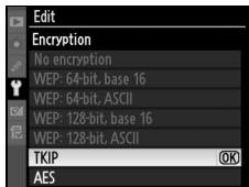
2 Return to wireless menu (2/2).

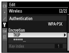
3 Highlight encryption key. Skip Steps 3-5 if [No encryption] was selected in Steps 1-2.
![NIKON WT-4 - Highlight encryption key. Skip Steps 3-5 if [No encryption] was selected in Steps 1-2. - 1](/content/2025/01/116040/images/0bf91b22e580918b4716f7b77be60eb836ae913c9d0e2a016bd3523134b05888.jpg)
![NIKON WT-4 - Highlight encryption key. Skip Steps 3-5 if [No encryption] was selected in Steps 1-2. - 2](/content/2025/01/116040/images/28e501a4371755d7e86a22ce8c8c4b7337e0e03a6f43d7245a23ecee7a870783.jpg)
4 Edit encryption key:
- Base 16: Press multi selector left or right to select character, up or down to change. 64-bit keys require 10 digits, 128-bit keys 26 digits, TKIP and AES keys 64

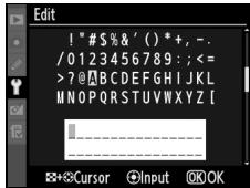
- ASCII: Enter key as described on page 26. 64-bit keys are 5 characters long, 128-bit keys 13 characters long, TKIP and AES keys 8 to 63 characters long.
5 Return to wireless menu (2/2).

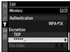
Key index: In infrastructure networks that use WEP encryption, choose the key index used by the host or access point.
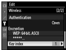
1 Choose index.

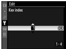
2 Return to wireless menu (1/2).

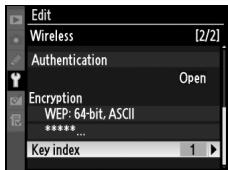
TCP/IP
Adjust TCP/IP settings as described on the following pages. The TCP/IP menu has two pages of options; to scroll between pages, press the multi selector up or down.

TCP/IP Menu, Page 1/2
Obtain automatically: Highlight this option and press the multi selector right to toggle it on (☑) or off. Turn this option on if the wireless network is configured to supply an IP address automatically by DHCP server or Auto IP (pg. 180). Otherwise turn it off and enter the address and sub-net mask supplied by the network administrator as described below.
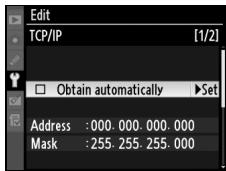
1 Highlight [Address].

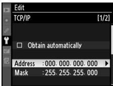
2 Enter edit mode.

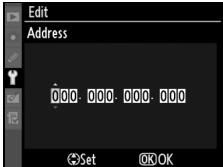
3 Press multi selector left or right to select, up or down to change.

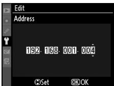
4 Exit to TCP/IP menu (1/2). If sub-net mask is required, proceed to Step 5.

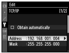
5 Highlight [Mask].
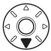
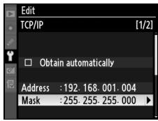
6 Enter edit mode.


7 Choose sub-net mask.

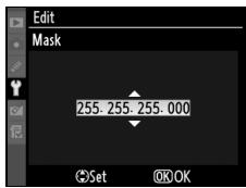
8 Exit to TCP/IP menu (1/2).

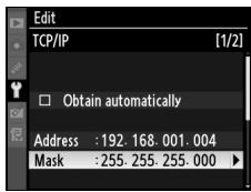
TCP/IP Menu, Page 2/2
Use gateway: Highlight this option and press the multi selector right to toggle it on (☑) or off. If the network requires a gateway address, turn this option on and enter the address supplied by the network administrator as described below.

1 Highlight [Address].

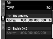
2 Enter edit mode.


3 Press multi selector left or right to select, up or down to change.

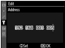
4 Return to TCP/IP menu (2/2).

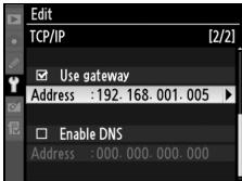
Enable DNS: Highlight this option and press the multi selector right to toggle it on (☑) or off. If a Domain Name Server (DNS) exists on the network, turn this option on and enter the address supplied by the network administrator as described below.
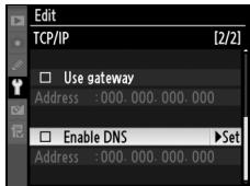
1 Highlight [Address].
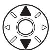
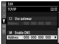
2 Enter edit mode.

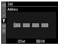
3 Press multi selector left or right to select, up or down to change.

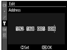
4 Return to TCP/IP menu (2/2).

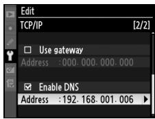

FTP
Adjust ftp settings as described on the following pages. The ftp menu has three pages of options; to scroll between pages, press the multi selector up or down.
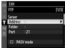
FTP Menu, Page 1/3
Server
1 Highlight [Address].
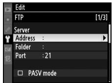
2 Display text entry dialog.

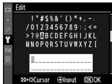
3 Enter server address (required; pg. 153).

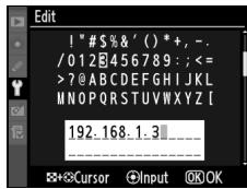
4 Return to ftp menu (1/3).

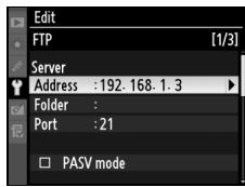
5 Highlight [Folder].

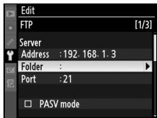
6 Display text entry dialog.

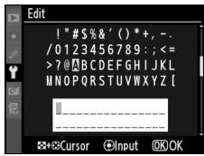
7 Enter destination folder name (pg. 153).

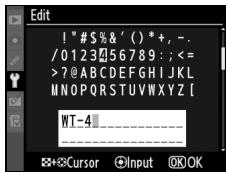
8 Return to ftp menu (1/3).

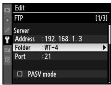
9 Highlight [Port].
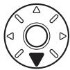
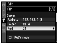
10 Enter edit mode.


11 Press multi selector left or right to select, up or down to change.

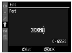
12 Return to ftp menu (1/3).

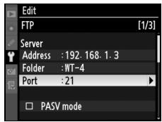
PASV mode: Highlight this option and press the multi selector right to toggle PASV mode on (☑) or off. Turn this option off to use normal (PORT) mode. Be sure the server supports PASV mode before turning this option on.
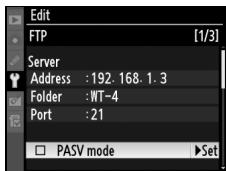
FTP Menu, Page 2/3
Anonymous login: Highlight this option and press the multi selector right to toggle it on (☑) or off. Turn this option on for anonymous login, off to enter a user name and password as described below.
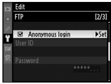
1 Highlight [UserID].

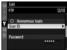
2 Display text entry dialog.

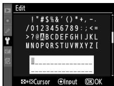
3 Enter user name (pg. 153).

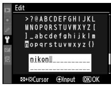
4 Return to ftp menu (2/3).

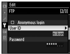
5 Highlight [Password].

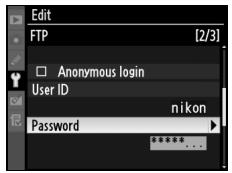
6 Display text entry dialog.

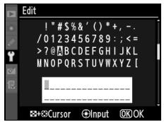
7 Enter password (pg. 153).

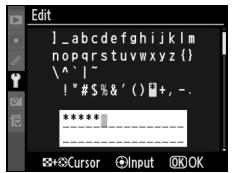
8 Return to ftp menu (2/3). Password is disguised as a row of dots.

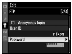
FTP Menu, Page 3/3
Use proxy server: Highlight this option and press the multi selector right to toggle it on (☑) or off. If a proxy server is required for ftp, turn this option on and enter an address and port number as described below.
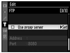
1 Highlight [Address].

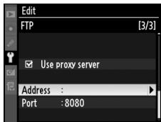
2 Display text entry dialog.


3 Enter proxy server address (pg. 153).

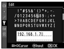
4 Return to ftp menu (3/3).

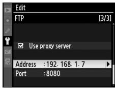
5 Highlight [Port].

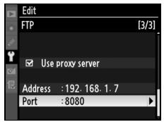
6 Enter edit mode.


7 Press multi selector left or right to select, up or down to change.

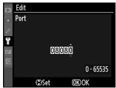
8 Return to ftp menu (3/3).

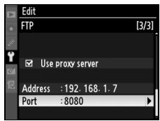
Transfer Settings (Transfer Mode Only)
The following settings are available in transfer mode:
Auto Send
Choose whether to upload photographs to the server as they are taken.
| Option | Description |
| 0n | Photos are uploaded immediately after being recorded to camera memory card. * Be sure memory card is inserted in camera before shooting. |
| 0ff (default) | Photos are not automatically uploaded as they are taken. Photos can be selected for transmission when camera is in playback mode. |
- Pictures will not be uploaded to the server when the WT-4 is turned off. Pictures will instead be marked with a "send" indicator as they are recorded to the memory card.
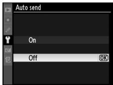
Delete After Send?
Select [Yes] to delete photographs from the camera memory card automatically once upload is complete (the default option is [No]). Deletion is suspended during live view, slide shows, and playback zoom and while the [Delete], [Hide image], [Copy
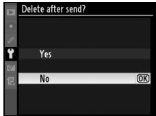
image(s)] (D3 only), [Slide show], [Print set], [White balance] (preset manual), [Retouch], [Choose slot] (D3 only) and [Choose folder] (D300 only) menus are displayed and resumes when these operations end.
Send File As
When uploading NEF + JPEG images to an ftp server, choose whether to send both NEF (RAW) and JPEG files or only the JPEG files.
| Option | Description |
| NEF (RAW) + JPEG (default) | Upload both NEF (RAW) and JPEG files. JPEG files are sent first. |
| JPEG only | Upload JPEG files only. |
Send Folder
All files in the selected folder (including those already marked as "sent") will be uploaded, beginning when the folder is selected.
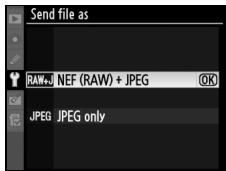
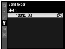
Deselect All?
Select [Yes] to remove "send," "sending," and "sent" marking from all images on the memory card. Upload of any images marked with a "sending" icon will immediately be terminated.

Print (Print Mode Only)
Choose a printer from the profile list. Once a connection has been established, photographs can be printed as described in the camera manual. This option is only available when the WT-4 is connected to the camera via USB and the WT-4 is on.
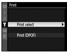
Print Mode
The following restrictions apply to the WT-4 print mode option:
- NEF (RAW) and TIFF images can not be printed. To print images in these formats, transfer them to the computer and use ViewNX (supplied) or optional software packages such as Capture NX.
- Index print is not available.
- Images will not be played back in the camera monitor when the button is pressed.
Device Info
This menu displays the following information about the WT-4. This option is only available when the WT-4 is connected to the camera via USB and the WT-4 is on.
Battery Info
Displays information on the battery inserted in the WT-4. The [Charging life] display shows battery age; replace [Charging life] reaches [4].
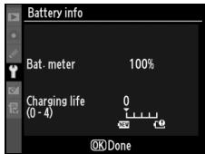
MAC Address
Shows the MAC address of the WT-4.
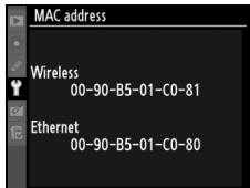
Firmware Version
Displays the WT-4 firmware version.
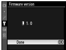
Device Settings
Format the transmitter's internal memory and choose the delay before the WT-4 turns off automatically. This option is only available when the WT-4 is connected to the camera via USB and the WT-4 is on.
Auto Power Off
Set the time delay until the WT-4 power automatically turns off after the USB connection between the camera and WT-4 is terminated.
| Option | Description |
| Always On (default) | The WT-4 does not turn off automatically. |
| Auto off delay | Choose the delay before the WT-4 turns off automatically from 30 seconds, 1 minute, 10 minutes, and 30 minutes. |
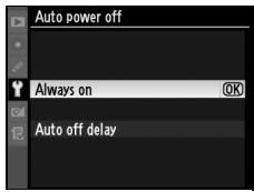
Format Transmitter's Memory
Format internal memory. All images and voice memos stored in internal memory will be deleted.
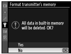
Appendices
Creating ftp Profiles Using Camera Menus
In transfer mode, the camera menus can be used in place of the WT-4 Setup Utility to create ftp profiles. Before creating an ftp profile with the camera menus, set the camera [USB] option to [MTP/PTP] and connect the WT-4. To prevent unexpected loss of power, be sure the battery is fully charged or use an optional AC adapter.
1 Open the WT-4 USB connector cover and connect the USB cable from the WT-4 to the camera USB connector.
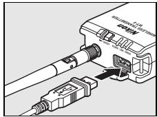
2 Turn the camera on.
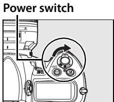
Using the Menu
If the shutter-release button on the camera is pressed while menus are displayed, the monitor will turn off and any changes to the current profile will be lost. Select [Monitor off delay] in the Custom Settings menu and choose a longer monitor off delay.
Firewalls
The WT-4 uses TCP ports 20 and 21 for ftp. It may be necessary to adjust firewall settings before connecting to a server behind a firewall.
Editing Existing ftp Profiles
See the Menu Guide for information on using camera menus to edit existing ftp profiles.
3 Turn on the WT-4.
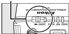
Power switch
4 Select [Transfer mode] for [Wireless transmitter] > [Mode] (pg. 152).
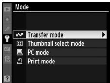
5 A profile list will be displayed showing the connections available in transfer mode. Highlight [FTP registration] and press the multi selector to the right. Note a new ftp profile can not be created if the camera already contains nine profiles; if necessary, delete a profile using
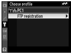
6 The registration dialog shown at right will be displayed. Press or to highlight an option, then press to the right to select. Select [Done] to proceed to Step 5 when settings are complete.
Rename: The dialog shown at right will be displayed. Enter a profile name of up to 16 characters as described in "Text Entry" (pg. 153) and press the 念 button to return to the registration dialog.
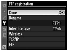
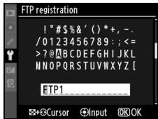
Interface type: The dialog shown at right will be displayed. Highlight one of the following options and press the ^ button to return to the registration dialog.
| Option | Description |
| Wireless & Ethernet (default) | Connect via wireless and/ or Ethernet. |
| Ethernet only | Connect via Ethernet only. |
Wireless: If [Wireless & Ethernet] is selected for [Interface type], select this option to adjust wireless settings as described in the Menu Guide (pp. 154-157). Press to return to the registration dialog when settings are complete.
TCP/IP: Adjust TCP/IP settings as described in the Menu Guide (pp. 158-161). Press to return to the registration dialog when settings are complete.
FTP: Adjust ftp settings as described in the Menu Guide (pp. 162-168). Press to return to the registration dialog when settings are complete.
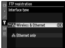

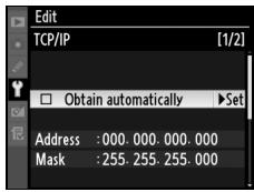

7 A confirmation dialog will be displayed. Choose from the following options:
- Yes: Open a connection to the new server and return to the top level of the wireless transmitter menu.
- No: Return to Step 3 without connecting to the server.
Errors
An error will be displayed if the new profile does not match server settings. Edit wireless, TCP/IP, and ftp settings as described in the Menu Guide (pg. 153).
Troubleshooting
6n
| Problem | Solution | Page |
| “POWER” LED does not light. | ·Turn the WT-4 on. | 71,82,91,103,141 |
| ·Confirm that the battery is inserted and fully charged. | 8,172 | |
| [Wireless transmitter] option not available. | ·Select [MTP/PTP] for [USB] option in camera setup menu. | 7 |
| ·Confirm that the WT-4 is connected and on. | 70,81,90,102,140 | |
| The [Print], [Device info], and [Device settings] menus cannot be selected. | Confirm that the WT-4 is connected and on. | 70,81,90,102,140 |
| Excessive radio interference. | Reorient the antenna. | — |
| All LEDs blink at once. | WT-4 hardware or battery malfunction. Contact a Nikon-authorized service representative. | — |
| Camera displays TCP/IP or FTP error. | ·Check settings for host and/or wireless LAN adapter and adjust camera settings appropriately. | 54,65,123,134,153 |
| ·Check firewall settings. | 5 | |
| Camera displays wireless error. | ·Confirm that host and wireless LAN adapter are on. | — |
| ·Ensure that there are no obstacles between WT-4 and wireless LAN adapter. | — | |
| ·Check settings for host and/or wireless LAN adapter and adjust camera settings appropriately. | 54,65,123,134,153 | |
| Camera displays “Ethernet cable is not connected”. | Connect Ethernet cable or change interface setting to [Wireless & Ethernet]. | 51,62,121,131,177 |
| Memory card error displayed. | Confirm that memory card is properly inserted. | 102 |
| Error displayed stating that no images are available for printing. | Only JPEG images can be printed from the camera. Transfer NEF (RAW) and TIFF images to computer and print them using Capture NX (available separately) or ViewNX. | — |
| Transfer interrupted before all photographs are sent. | Transfer will resume if WT-4 is turned off and then on again. | 71, 82, 91, 103, 141 |
| USB cable disconnected during transmission. | Reconnect the USB cable. Do not turn the camera off. | — |
Glossary
Ad-hoc: Devices in an ad-hoc wireless network communicate directly ("peer to peer"), without a wireless access point.
AES (Advanced Encryption Standard): An encryption standard developed for use by the American government. AES has been praised for combining strong encryption with rapid processing.
Auto IP (APIPA—Automatic Private IP Addressing): Allows devices in a network to automatically assign themselves unique IP addresses if no DHCP server is found on the network. Auto IP uses addresses from 169.254.1.0 to 169.254.254.255 and a sub-net mask of 255.255.0.0. These addresses are neither global nor private but are reserved for Auto IP.
BSS-ID (Basic Service Set ID): All wireless devices on an ad-hoc wireless network share the same BSS-ID. The BSS-ID may be up to thirty-two characters long and is case sensitive. See also Ad-hoc.
Channel: When multiple wireless LANs with different ESS-IDs are operating on a single frequency within a given area, transmission speeds will drop. Specifying a separate channel (frequency) for each network can prevent interference and increase transmission speeds (note that all devices in the same network must be set to the same channel). In the IEEE 802.11a standard, the 5 GHz band is divided into 19 channels, each separated by 20MHz . In the IEEE 802.11b/g standard, the 2.4 GHz band is divided into 14 channels, each separated by 4MHz .
DHCP (Dynamic Host Configuration Protocol) Server: Each device in a TCP/IP network requires an IP address. If a DHCP server is present on the network, IP addresses will be assigned automatically.
DNS (Domain Name Server): A server that contains a database of IP addresses and host names for the machines it administers and that converts host names to IP addresses in response to queries from clients. Each DNS can also query other Domain Name Servers for addresses not listed in its database.
ESS-ID (Extended Service Set ID): Multiple BSSs can be configured to form an ESS, allowing users to roam between wireless access points. Only devices with the same ESS-ID as a given access point can communicate with that access point. The ESS-ID may be up to thirty-two characters long and is case sensitive.
Ethernet: The name given to the IEEE 802.3 LAN standard. Devices in an Ethernet network are connected via UTP cables for transmission speeds of up to 10 Mbps (10 base-T) or 100 Mbps (100 base-TX).
Gateway: A network node that acts as an entrance to another network, for example between a company network and the Internet.
IEEE 802.11a/b/g: Wireless LAN standards proposed by the 802 committee, which develops LAN technology standards for the IEEE.
IIS (Internet Information Services): Microsoft's name for its Web server software. Notable for its close connection to Windows-based systems through Active Server Pages (ASPs). When installed as part of the operating system, IIS makes it relatively easy to build web a server.
Infrastructure: Devices in an infrastructure network communicate via wireless access points that may be connected to an Ethernet network, allowing wireless and Ethernet devices to coexist on a single network.
IP address: The address given to each node in a TCP/IP network. All nodes in a TCP/IP network must have a unique IP address. Private IP addresses are recommended for nodes that are part of a local network.
Key index: A number identifying which WEP key is to be used for encryption when communicating via an access point with more than one WEP key. All devices on the network must use the same key index.
LAN (Local Area Network): A network of computers located in relatively close proximity to one another. LANs generally support data transfer speeds of 10-100 Mbps.
MAC (Media Access Control) Address: A unique hardware address for each device on a network, required when sending and receiving packets.
Open system: The name given to a wireless network using no authentication (open authentication). Open systems are relatively insecure, as a password is not required to gain access to the server.
PASV mode: PASV mode is used by clients behind firewalls, when it allows the ftp server to supply the port number.
Private IP address: An IP address that is only visible within a local network. Because packets using a private IP address can not be transmitted to another network, they are usually sent between networks via a proxy server or NAT. Private IP addresses in the range 10.0.0.0–10.255.255.255 are termed "class A." Class B addresses are in the range 172.16.0.0–172.31.255.255, class C addresses in the range 192.168.0.0–192.168.255.255. The class of address used depends on the size of the network. Class C addresses are often used for small networks.
Protocol: A set of rules for passing information back and forth between devices in a network. By defining such elements of communication as how links are established, how receipt of a signal is acknowledged, how data are encoded, and how to handle errors, a protocol ensures that data are transmitted without loss of information.
Proxy: A server that stands between large networks and local networks or computers, typically to ensure security. One element of a firewall.
PTP-IP (Picture Transfer Protocol over Internet Protocol): A commonly used name for the CIPA DC-005-2005 image transfer protocol for transmitting images over LANs. It represents an extension to the Picture Transfer Protocol (PTP) used to transfer images between cameras and computers connected via USB cable. The WT-4 uses PTP-IP to communicate with host computers.
Shared key: An authentication system in which WEP keys are used to establish whether a client has access to the network. Communication is restricted to devices with the same WEP key.
SS-ID (Service Set ID): An SS-ID prevents interference between devices in different networks by allowing communication only between devices that share an SS-ID. See BSS-ID, ESS-ID.
Sub-net mask: A mask that divides a network into sub-nets.
TCP/IP (Transmission Control Protocol/Internet Protocol): A dual protocol consisting of a transport-layer protocol (TCP) that divides data into packets which it later reassemblies, and a network protocol (IP) that handles transmission of the packets between points in the network. It can be implemented on different platforms, allowing data to be transmitted between machines with different operating systems.
TKIP (Temporal Key Integrity Protocol): An encryption standard using dynamic WPA-PSK keys that change periodically or after a specified amount of data have been transmitted, making it more secure than WEP, which uses fixed keys.
UDP (User Datagram Protocol): A fast but unreliable transport layer transmission protocol using the OSI model.
USB (Universal Serial Bus): A standard for connecting peripheral devices. USB supports data transfer rates of up to 480 Mbps (USB 2.0). Devices connected via USB can be connected and disconnected with the power on ("hot plug") and do not require separate IRQ (interrupt request) numbers, preventing conflicts with other devices.
WAN (Wide Area Network): A network connecting computers or LANs in widely separated locations. The Internet is an example of a WAN.
WEP (Wired Equivalent Privacy): A type of encryption in which the data transmitted between devices is encoded using a shared encryption key (WEP key).
Wireless LAN access point: A wireless transceiver that acts as the connection between wireless devices and a wireless network.
WPA-PSK (WiFi Protected Access with Pre-Shared Key): A type of authentication for wireless networks using previously-established (pre-shared) TKIP or AES keys. Wireless devices using this form of authentication can only communicate with devices with the same pre-shared key.
Specifications
■ Wireless Transmitter WT-4/WT-4A/WT-4B/WT-4C/WT-4D/WT-4E
Wireless
| Standards | WT-4/WT-4A/WT-4B/WT-4C/WT-4D: IEEE 802.11a/b/g, ARIB STD-T66, ARIB STD-T71 WT-4E: IEEE 802.11b/g, ARIB STD-T66 |
| Communications protocols | IEEE 802.11a/g: OFDM IEEE 802.11b: DBPSK, DQPSK, CCK |
| Operating frequency | WT-4: 5170-5320 MHz (34/36/38/40/42/44/46/48/52/56/60/64) 2412-2472 MHz (1-13) WT-4A: 5180-5320 MHz (36/40/44/48/52/56/60/64) 5745-5825 MHz (149/153/157/161/165) 2412-2462 MHz (1-11) WT-4B: 5180-5320 MHz (36/40/44/48/52/56/60/64) 5500-5700 MHz (100/104/108/112/116/120/124/128/132/136/140) 2412-2472 MHz (1-13) WT-4C: 5180-5320 MHz (36/40/44/48/52/56/60/64) 5745-5825 MHz (140/153/157/161/165) 2412-2472 MHz (1-13) WT-4D: 5745-5825 MHz (140/153/157/161/165) 2412-2472 MHz (1-13) WT-4E: 2412-2462 MHz (1-11) |
| Range (line of sight)* | IEEE802.11a: Approximately 260 m (853 ft.) IEEE802.11b/g: Approximately 180 m (590 ft.) |
| Data rates† | IEEE 802.11a/g: 6, 9, 12, 18, 24, 36, 48, and 54 Mbps IEEE 802.11b: 1, 2, 5.5, and 11 Mbps |
| Security | TKIP, AES, 128/64-bit (104/40-bit) WEP |
| Access protocols | Infrastructure/ad-hoc |
- With large antenna at wireless LAN access point. Range may vary with signal strength and presence or absence of obstacles.
Maximum logical data rates according to IEEE standard. Actual rates may differ.
| Ethernet | |
| Standards | IEEE 802.3u (100 base-TX)/IEEE 802.3 (10 base-T) |
| Data rates | 10/100 Mbps with auto detect |
| Port | 100 base-TX/10 base-T (AUTO-MDIX) |
| Data transfer protocols | PTP-IP, ftp |
| Power consumption | 4.5 W maximum |
| Power source | Rechargeable EN-EL3e Li-ion battery ×1 (available separately), EH-6 AC adapter (available separately) |
| Operating environment | Temperature: 0–40 °C (32–131 °F) Humidity: less than 85% (no condensation) |
| Weight | 131 g/4.6 oz. (body only) |
| Dimensions (W × H × D) | 65 mm × 125 mm × 35 mm (2.6 in. × 4.9 in. × 1.4 in.) |
Battery Life
The length of time batteries can be used and the number of shots that can be uploaded before recharging varies with the condition of the batteries, signal strength, and how camera and WT-4 are used. The following measurements were performed using a fully-charged EN-EL3e battery (1500 mAh) at a temperature of 23^ ( 73.4^ ) while continuously uploading images with an average file size of 3 Mbytes to a host computer running Windows Vista Ultimate over an infrastructure network with the WT-4 in transfer mode.
| Network | Wireless (802.11a) | Wireless (802.11g) | Ethernet (100 base-TX) |
| No. of shots uploaded | 4,500 | 4,500 | 10,000 |
| Battery life | 150 min. (2.5 hr.) | 150 min. (2.5 hr.) | 200 min. (3.3 hr.) |
To ensure maximum battery performance:
- Keep the battery contacts clean. Soiled contacts can reduce battery performance.
- Use EN-EL3e batteries immediately after charging. Batteries will lose their charge if left unused.
- Periodically check the battery level using [Wireless Transmitter] > [Device info] > [Battery info].
- The battery level displayed by the camera may vary with changes in temperature.
Index
Symbols


76,147
A
ACAdapter 9
Ad-hoc 16, 17, 26, 38, 48, 72, 83, 92, 105, 119, 142, 154, 180
Antenna 2,3,8,178
[Auto power off] 9,173
[Auto send] 169
B
[Battery info] 172
BSS-ID 30,36,54,65,154,180
C
Camera Control Pro 2 4,90,94
Channel 41,54,123,155,183
Connecting the WT-4 70,81,90,102,140,175
D
[Delete after send?] 169
[Deselect all?] 170
[Device info] 172
[Device settings] 173
DHCP server 56,67,125,136,158,180
Domain Name Server (DNS) 56, 67, 125, 136, 161, 180
E
Encryption 19,21,23,30,32,36,41,42,45,54,65,123,134,156
key 19,21,23,30,32,36,41,42,45,54,65,123,134,156
Errors 178
ftp 178
TCP/IP 178
wireless 178
ESS-ID 30,36,54,65,154,180
Ethernet 2,4,5,51,62,121,131,177,178,180
F
File names 78,146,149
[Firmware Version] 172
Folders 50,61,75,87,113,116,126,137,163
[Format transmitter's memory] 173
[FTP] 162,177
ftp server 108, 126, 137, 162
G
Gateway 125, 136, 160, 180
Infrastructure 16,21,32,42,59,129,154,181
IP address 56,67,110,115,117,125,136,158,177,181
M
[MAC address] 172
Memory cards 70,81,102
151-173, 175-177
entering text in 153
[Mode] 4,71,82,91,103,152
P
password 50,61
PASVmode 126,137,164,181
PC mode 4,90
Port 5,112,116,126,137,163,175
[Print] 171
Print mode 4,97
Printing 4,102,171
Proxy 126, 137, 167, 181
PTP-IP 182,184
s
[Send file as] 170
[Send folder] 170
SS-ID 30,36,54,65,123,134,154,182
Status LEDs 2,3,77,88,95,104
T
[TCP/IP] 158,177
TCP/IP 56,67,125,136,158,177,182
Thumbnail select mode 4, 79
Transfer mode 4,70,176
[Transfer Settings] 169
U
Upload 70,74,145
deleting images after 169
Interrupting 75,146
selecting images for 74,145
[USB] 7
User ID 126, 137, 165
W
[Wireless] 154, 177
Wireless LAN 16
access point 16,21,32,42,64,133,154,182
[Wireless transmitter] 151
WT-4 Setup Utility 10,48,97,119
No reproduction in any form of this manual, in whole or in part (except for brief quotation in critical articles or reviews), may be made without written authorization from NIKON CORPORATION.