
WT-2 - Wireless transmitter NIKON - Free user manual and instructions
Find the device manual for free WT-2 NIKON in PDF.

| Product Type | Wireless transmitter for compatible Nikon cameras |
| Wireless Standard | IEEE 802.11b/g |
| Data rates | Up to 54 Mbit/s (802.11g), 11 Mbit/s (802.11b) |
| Range (with standard antenna WA-S1) | Approx. 30 m (line of sight) |
| Range (with long-range antenna WA-E1) | Approx. 150 m (line of sight) |
| Operating frequency | WT-2: 2412–2472 MHz (13 channels); WT-2A: 2412–2462 MHz (11 channels) |
| Security | WEP 64/128-bit, TKIP |
| Supported protocols | FTP (image transfer), PTP/IP (remote control) |
| Dimensions (W × H × D) | 146.5 × 34.5 × 65.5 mm |
| Weight (without antenna) | 210 g |
| Power consumption | Max 3.4 W (standby: 200 mA, transmitting: 250 mA at 13.5 V) |
| Power supply | Via the camera's power contact (USB cable required) |
| Operating temperature | 0°C to 40°C |
| Operating humidity | Up to 85% (without condensation) |
| Package contents | WT-2 transmitter, standard antenna WA-S1, USB cable, Wireless Connecting Utility software CD, User's Manual |
| Compatibility | Nikon cameras with USB connector and PTP mode |
| Indicator lights | POWER (green), LINK (orange), BUSY (green) |
| Antenna | Removable (standard WA-S1 supplied, long-range WA-E1 optional) |
| Mounting on the camera | Locking ring on the tripod socket thread |
| Care and cleaning | Keep dry, do not disassemble, use a soft cloth for cleaning |
| Safety | Do not expose to water, do not use in flammable gas environments, follow hospital/aircraft instructions |
| Spare parts and repairability | Long-range antenna WA-E1 available separately; repair by Nikon authorized center |
| General information | Compliant with FCC Class B; for home or office use |
Frequently Asked Questions - WT-2 NIKON
User questions about WT-2 NIKON
0 question about this device. Answer the ones you know or ask your own.
Ask a new question about this device
Download the instructions for your Wireless transmitter in PDF format for free! Find your manual WT-2 - NIKON and take your electronic device back in hand. On this page are published all the documents necessary for the use of your device. WT-2 by NIKON.
USER MANUAL WT-2 NIKON
Wireless Transmitter
Wireless Transmitter
WT-2
Trademark Information
Macintosh and Mac OS are trademarks of Apple Computer, Inc. Microsoft and Windows are registered trademarks of Microsoft Corporation. All other trade names mentioned in this manual or the other documentation provided with this Nikon product are trademarks or registered trademarks of their respective holders.
Apple Public Source License
This product includes Apple mDNS source code that is subject to the terms of the Apple Public Source License located at URL http://developer.apple.com/darwin/.
Portions Copyright (c) 1999-2004 Apple Computer, Inc. All Rights Reserved.
This file contains Original Code and/or Modifications of Original Code as defined in and that are subject to the Apple Public Source License Version 2.0 (the 'License'). You may not use this file except in compliance with the License. Please obtain a copy of the License at http://www.opensource.apple.com/apsl/ and read it before using this file.
The Original Code and all software distributed under the License are distributed on an 'AS IS' basis, WITHOUT WARRANTY OF ANY KIND, EITHER EXPRESS OR IMPLIED, AND APPLE HEREBY DISCLAIMS ALL SUCH WARRANTIES, INCLUDING WITHOUT LIMITATION, ANY WARRANTIES OF MERCHANTABILITY, FITNESS FOR A PARTICULAR PURPOSE, QUIET ENJOYMENT OR NON-INFRINGEMENT. Please see the License for the specific language governing rights and limitations under the License.
For Your Safety
To prevent damage to your Nikon product or injury to yourself or to others, read the following safety precautions in their entirety before using this equipment. Keep these safety instructions where all those who use the product will read them.
The consequences that could result from failure to observe the precautions listed in this section are indicated by the following symbol:

This icon marks warnings, information that should be read before using this Nikon product to prevent possible injury.
WARNINGS

Do not disassemble
Failure to observe this precaution could result in fire, electric shock, or other injury. Should the product break open as the result of a fall or other accident, disconnect the camera power source and take the product to a Nikon-authorized service representative for inspection.

Turn camera off immediately in the event of malfunction
Should you notice smoke or an unusual smell coming from the equipment, immediately remove the battery from the camera, taking care to avoid burns. Continued operation could result in injury. After removing the battery, take the equipment to a Nikon-authorized service representative for inspection.

Keep dry
Do not immerse in or expose to water or rain. Failure to observe this precaution could result in fire or electric shock.

Do not use in the presence of flammable gas
Failure to observe this precaution could result in explosion or fire.

Do not handle with wet hands
Failure to observe this precaution could result in electric shock.

Keep out of reach of children
Failure to observe this precaution could result in injury.

Follow the instructions of hospital and airline personnel
This device emits radio frequency radiation that could interfere with medical or navigational equipment. Do not use this device in a hospital or on board an airplane without first obtaining the permission of hospital or airline staff.

Do not expose to high temperatures
Do not leave the device in a closed vehicle under the sun or in other areas subject to extremely high temperatures. Failure to observe this precaution could result in fire or in damage to the casing or internal parts.

Observe caution when using the WA-E1
When using the WA-E1 extended range antenna (available separately), be careful not to put the tip of the antenna in your eye accidentally. Failure to observe this precaution could result in blindness or other visual impairment.
Notices
- No part of the manuals included with this product may be reproduced, transmitted, transcribed, stored in a retrieval system, or translated into any language in any form, by any means, without Nikon's prior written permission.
-
Nikon reserves the right to change the specifications of the hardware and software described in these manuals at any time and without prior notice.
-
Nikon will not be held liable for any damages resulting from the use of this product.
- While every effort has been made to ensure that the information in these manuals is accurate and complete, we would appreciate it were you to bring any errors or omissions to the attention of the Nikon representative in your area (address provided separately).
Notice for Customers in the U.S.A.
U.S.A. Federal Communications Commission (FCC)
Declaration of Conformity
This device complies with Part 15 of the FCC rules. Operation of the device is subject to the following two conditions: (1) this device may not cause harmful interference, and (2) this device must accept any interference received, including interference that may cause undesired operation.
Products that contain a radio transmitter are labeled with FCC ID and may also carry the FCC logo.
Nikon
WT-2A

Tested To Comply
With FCC Standards
FOR HOME OR OFFICE USE
FCC Radio Frequency Interference Statement
This equipment has been tested and found to comply with the limits for a Class B digital device, pursuant to Part 15 of the FCC rules. These limits are designed to provide reasonable protection against harmful interference in a residential installation. This equipment generates, uses, and can radiate radio frequency energy and, if not installed and used in accordance with the instructions, may cause harmful interference to radio communications. However, there is no guarantee that interference will not occur in a particular installation. If this equipment does cause harmful interference to radio or television reception, which can be determined by turning the equipment off and on, the user is encouraged to try to correct the interference by one or more of the following measures:
- Reorient or relocate the receiving antenna.
- Increase the separation between the equipment and receiver.
- Connect the equipment into an outlet on a circuit different from that to which the receiver is connected.
- Consult the dealer or an experienced radio/television technician for help.
FCC Radiation Exposure Statement
The available scientific evidence does not show that any health problems are associated with using low power wireless devices. There is no proof, however, that these low power wireless devices are absolutely safe. Low power Wireless devices emit low levels of radio frequency energy (RF) in the microwave range while being used. Whereas high levels of RF can produce health effects (by heating tissue), exposure to low level RF that does not produce heating effects causes no known adverse health effects. Many studies of low level RF exposures have not found any biological effects. Some studies have suggested that some biological effects might occur, but such findings have not been confirmed by additional research. The Wireless Transmitter (WT-2A) has been tested and found to comply with the Federal Communications Commission (FCC) guidelines on radio frequency energy (RF) exposures. The maximum SAR levels tested for the Wireless Transmitter (WT-2A) has been shown to be 0.267 W/kg at Head.
This device should not be co-located or operated with any other antenna or transmitter.
CAUTION
Modifications
The FCC requires the user to be notified that any changes or modifications made to this device that are not expressly approved by Nikon Corporation may void the user's authority to operate the equipment.
Notice for customers in the State of California, U.S.A.
WARNING: Handling the cord on this product will expose you to lead, a chemical known to the State of California to cause birth defects or other reproductive harm. Wash hands after handling.
Nikon Inc.,
1300 Walt Whitman Road, Melville, New York
11747-3064, U.S.A.
Tel.: 631-547-4200
Notice for customers in Canada CAUTION
This class B digital apparatus meets all requirements of the Canadian Interference Causing Equipment Regulations.
ATTENTION
Notice for Customers in the U.S.A...... ii
Notice for customers in Canada ..... iii
Introduction.... 1
Supported Protocols ......2
ftp 2
PTP/IP 2
Parts of the WT-2 3
Setup 4
Step 1—Connect the WT-2....4
Step 2—Select PTP....5
Uploading Images: ftp Mode...... 5
Setup Using the Connection Wizard ......6
Connecting to the Server 9
Uploading Images 10
Interrupting Transmission 11
The Icon 11
Network Status....12
Controlling the Camera: PTP/IP Mode... 14
Installing Pairing Software....14
Setup Using the Connection Wizard .....15
Pairing 17
Connecting to the Computer 20
Controlling the Camera 21
Network Status....22
Menu Guide 24
Wireless LAN system 24
Mode....24
Settings 24
Network Settings 25
Pairing Options (PTP/IP Mode Only) ......36
Auto Send (FTP Mode Only) 37
Delete After Send (FTP Mode Only)......37
Send File As (FTP Mode Only)......38
Send Folder (FTP Mode Only) 38
Deselect All (FTP Mode Only)......38
Appendices 39
Installing Pairing Software....39
Installation (Windows XP)......39
Installation (Mac OS X) 41
Sample ftp Settings 42
Preparation....42
Building a Network 43
Configuring the Server 43
Configuring the Wireless LAN Adapter ....45
Configuring the WT-2......46
Uploading Pictures....48
Troubleshooting....50
Glossary....51
Specifications 54
Index 55
Introduction
Thank you for purchasing a WT-2 or WT-2A wireless transmitter for compatible Nikon digital cameras. The WT-2 is for use only in Austria, Belgium, Denmark, Finland, France, Germany, Greece, Italy, Japan, the Netherlands, Portugal, Spain, Sweden, Switzerland, and the United Kingdom. The WT-2A is for use only in Canada and the United States of America. The principal difference between the WT-2 and WT-2A is in the number of channels supported (see pg. 54); unless otherwise stated, all references to the WT-2 also apply to the WT-2A.
This manual describes how to connect the WT-2 and control the camera from a computer running Nikon Capture 4 version 4.2 or later (available separately) or transmit images to a server over a wireless LAN. Before using the WT-2, be sure to read the notices and warnings on pages i–iii.
The following symbols and conventions are used throughout this manual:

This icon marks cautions, information that should be read before use to prevent damage to the WT-2.

This icon marks notes, information that should be read before using the device.

This icon marks tips, additional information that may be helpful when using the WT-2.

This icon indicates that more information is available elsewhere in this manual.

Background Knowledge
This manual assumes basic knowledge of ftp servers and wireless local area networks (LAN). For more information on installing, configuring, and using devices in a wireless network, contact the manufacturer or network administrator.

Life-Long Learning
As part of Nikon's "Life-Long Learning" commitment to ongoing product support and education, continually-updated information is available on-line at the following sites:
- For users in the U.S.A.: http://www.nikonusa.com/
- For users in Europe and Africa: http://www.europe-nikon.com/support
- For users in Asia, Oceania, and the Middle East: http://www.nikon-asia.com/
Visit these sites to keep up-to-date with the latest product information, tips, answers to frequently-asked questions (FAQs), and general advice on digital imaging and photography. Additional information may be available from the Nikon representative in your area. See the URL below for contact information:
http://nikonimaging.com/
Supported Protocols
The WT-2 wireless transmitter is a wireless LAN adapter that allows the camera to be controlled remotely from a computer running Nikon Capture 4 version 4.2 or later (available separately) or photographs to be upload to an ftp server over a wireless LAN. The WT-2 supports the following protocols:
ftp (5)
New photographs and photographs stored on the camera memory card can be uploaded to an ftp server via a wireless LAN.
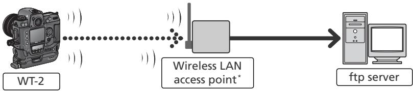
flowchart
graph LR
    A["WT-2 Device"] -->|Wireless LAN access point*| B["Wireless LAN"]
    B --> C["ftp server"]
* Infrastructure mode only; not required in ad-hoc mode (27).
PTP/IP (14)
The camera can be controlled from a computer on the same network and pictures saved directly to the computer hard disk using Nikon Capture 4 version 4.2 or later (available separately; connection via router not supported).
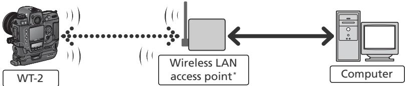
flowchart
graph LR
    A["WT-2"] -->|Wireless LAN access point*| B["Computer"]
    B -->|Wireless LAN access point*| A
* Infrastructure mode only; not required in ad-hoc mode (27).
An environment with a wireless LAN is required to use the WT-2. An ftp server is required for ftp. Operation has been confirmed on the following systems:
- ftp: Windows Server 2003, Windows 2000 Server, Windows XP Professional, Windows 2000 Professional, Mac OS X Server, Mac OS X. Internet ftp connections and ftp servers running third-party software are not supported.
- PTP/IP: Windows XP Professional, Windows XP Home Edition, Mac OS X (version 10.3 or later).
For the latest information on supported operating systems, see the Nikon website for your area (💡 1).
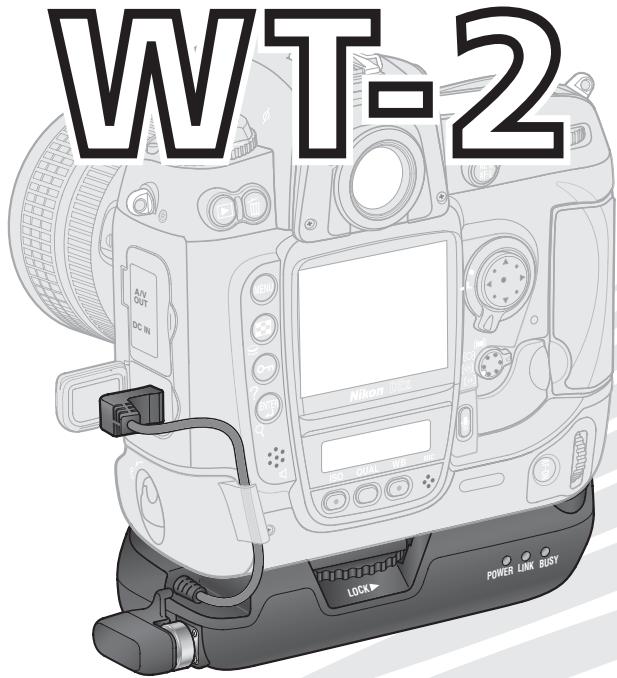
Parts of the WT-2
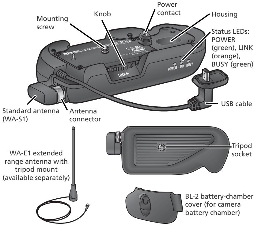
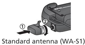
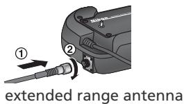
Attaching an antenna
Reorienting the Antenna
Before reorienting the WA-S1, unscrew it from the antenna connector. When using the WA-E1 (available separately), be careful not to kink or tug the cable.
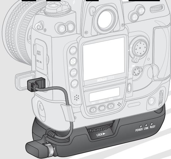
Step 1—Connect the WT-2
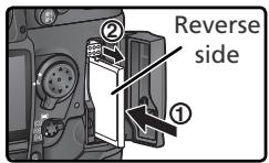
1 Turn the camera off.
2 Remove the cover protecting the camera power contact. The cover can be stored in the housing on the WT-2.
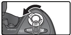
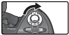
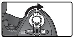
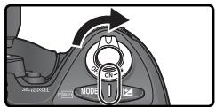
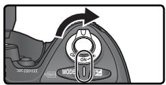
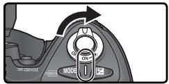
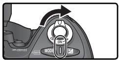
3 Place the camera on the WT-2 and rotate the knob in the direction shown to fasten the WT-2 to the camera tripod mount.
4 Open the camera USB connector cover and connect the USB cable to the USB connector.
5 Pass the cable over the guide on the BL-2 battery-chamber cover.

natural_image
Two-step diagram showing a mechanical component being inserted into a housing, with arrows indicating direction (no text or symbols present)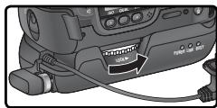
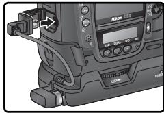
natural_image
Close-up of a camera module with adjustment knobs and a digital display (no visible text or symbols)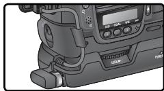
natural_image
Close-up of a professional video camera with LCD screen and buttons (no visible text or symbols)Disconnecting the WT-2
To disconnect the WT-2:
1 Turn the camera off.
2 Disconnect the USB cable.
3 Rotate the knob clockwise to unscrew the WT-2 from the camera tripod mount.
4 Replace the cover on the camera power contact.
Step 2—Select PTP
The camera must be in PTP mode to communicate with the WT-2.
1 Turn the camera on.
2 Set the USB option in the camera setup menu to PTP.
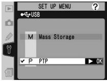
The Wireless LAN option in the camera setup menu will now be available. See "Menu Guide" (24) for details.
Uploading Images: ftp Mode
In ftp mode, photographs can be uploaded to an ftp server over a wireless network. The principal steps involved in connecting to an ftp server for the first time are as follows:
1—Adjusting Settings 6–8
2—Connecting to the Server.... 9
3—Uploading Images 10–11
Step 1 can be omitted once the WT-2 has been set up for connection to a particular server.

Firewalls
ftp mode uses TCP ports 20 and 21. It may be necessary to adjust firewall settings before connecting to a server behind a firewall.
Setup Using the Connection Wizard
First-time setup can be completed with the help of the Connection Wizard. Before starting the Connection Wizard, make sure that network is active and the destination ftp server is running. To prevent changes to settings from being lost should the camera monitor turn off automatically, use the optional AC adapter or choose the maximum camera monitor off delay.
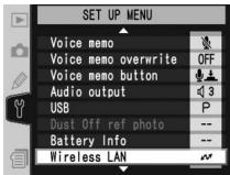
1 Turn the camera on.
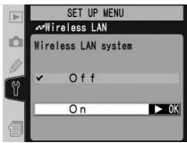
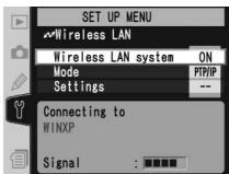
2 Check that Off is selected for the Wireless LAN > Wireless LAN system option in the camera setup menu 📋 24).
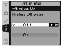
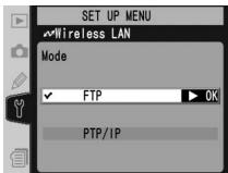
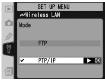
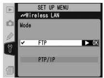
3 Select FTP for Wireless LAN>Mode (24).
Wireless Network Settings
For information on adjusting wireless network settings without using the Connection Wizard, see "Menu Guide" (26–35). See page 25 for information on loading settings files created with a computer.
ftp Mode Settings
In addition to the settings made with the Connection Wizard, the following options are available in ftp mode:
| Option | Description | |
| Auto send | Upload photos to server as they are taken. | 37 |
| Delete after send? | Delete photos from camera memory card after upload. | 37 |
| Send file as: | Send NEF+JPEG images as JPEG only or as NEF and JPEG. | 38 |
| Send folder | Upload all photos in selected folder. | 38 |
| Deselect all? | Deselect all images selected for upload. | 38 |
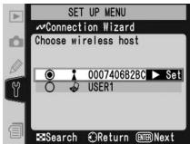
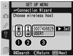
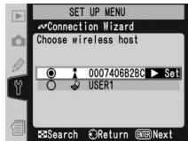
4 In the top level of the wireless LAN menu, press the Ⓧ button to start the Connection Wizard. A list of available connections will be displayed. Press the multi selector up or down to highlight the desired connection and press the multi selector to the right to select it.

① Selected connection is marked with Ⓞ icon.
② Infrastructure connections are marked with 🔊 icon, ad-hoc connections with 🔊 icon (27).
③ SS-ID (not displayed if SS-ID is unavailable).

Connection Not Available
If the desired connection is not listed, press the ⏻ button to search again. If the connection still can not be found, check settings on the network.
5 Press the ENTER button.

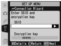
SS-ID
If prompted for an SS-ID, press the multi selector to the right and enter the connection SS-ID as described on page 26.


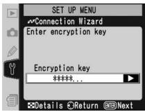
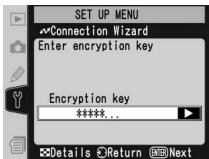
Encryption Key
If prompted for an encryption key, press the multi selector to the right and enter a key as described on page 27.
Errors
If an error is displayed, press the multi selector to the left to return to the previous dialog and enter a valid value for the affected setting.
Related Settings
To access advanced settings when entering data in steps 5–9, press the ☑ button. The related section of the network settings menu will be displayed (26–35).
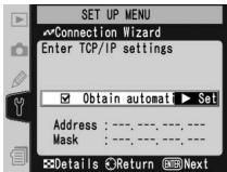
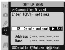
6 If the network is configured to supply an IP address automatically by DHCP server or Auto IP (51), press the multi selector to the right to select Obtain automatically. If the network requires a fixed IP address or subnet mask, enter the information supplied by the network administrator (28). Press the button to proceed to Step 7.
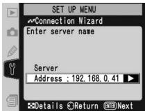
7 Press the multi selector to the right and enter the server URL or IP address as described on page 32. Press the ENTER button to proceed to Step 8.

"UNABLE TO LOCATE SERVER"
If this error is displayed, press the multi selector to the left to return to Step 6 or 7 and enter a valid IP address and server name.
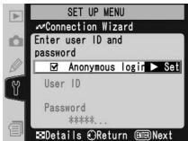
8 If anonymous login is permitted, press the multi selector to the right to select Anonymous login. Otherwise enter a user ID and password as described on page 33. Press the button to proceed to Step 9.
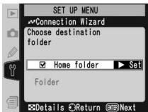
9 To upload images to the server's home directory (34), press the multi selector to the right to select Home folder. To choose a different folder, enter the folder name as described on page 34. Press the button to proceed to Step 10.
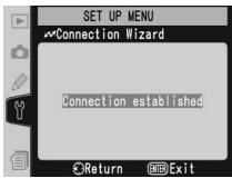
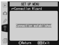
10 The dialog shown at right is displayed when setup is complete. Press the ENTER button to exit the wizard and return to the wireless LAN menu.
"WIRELESS ERROR," "TCP/IP ERROR," "FTP ERROR"
The above errors indicate that the associated wireless network options are set incorrectly. After checking settings for the host or access point, press the ⚙ button to restart the Connection Wizard and adjust camera settings to match. For more information, see "Sample ftp Settings" ⚙ 42).
Connecting to the Server
1 Turn the camera off and insert the memory card containing the pictures to be sent.
2 Turn the camera on.
3 Select FTP for the Wireless LAN>Mode option in the camera setup menu (24).
4 Select On for Wireless LAN>Wireless LAN system (24).
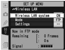
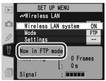
5 Confirm that "Now in FTP mode" is shown in the top level of the wireless LAN menu. For information on what to do if an error is displayed, see "Troubleshooting" (50).
Uploading Images
1 Press the 📋 button to view pictures on the memory card. Display the first picture to be sent in single-image playback or highlight it in the thumbnail list.
2 Press the center of the multi selector while pressing the Ⓒ button. The image will be marked with a white "send" icon and transmission will begin immediately. During upload, images are marked with a green "sending" icon. Repeat this process to send additional images (pictures will be sent in the order selected).
Images that have been successfully uploaded are marked with a blue “sent” icon.

natural_image
Illustration of a person by the sea with a sailboat and mountains in the background (no text or symbols)
natural_image
Two abstract circular icons: one with a checkered pattern inside a circle, the other with a triangular symbol inside a circle (no text or symbols)
natural_image
Illustration of a woman by the sea with a sailboat and mountains in the background (no text or symbols)
natural_image
Illustration of a person looking at a sailboat on water with mountains in the background (no text or symbols)During Upload
Do not remove the memory card from the camera during upload.
File Names
If the destination folder on the ftp server contains files with the same names as images selected for upload, the files on the server will be replaced by the images uploaded from the camera.
Loss of Signal
Transmission may be interrupted if the signal is lost (13). Transmission can be resumed by turning the camera off and then on again, activating the camera exposure meters, or selecting On for Wireless LAN > Wireless LAN system once the signal is restored.
Voice Memos
Voice memos can not be uploaded separately, but will be included when the associated pictures are transmitted.
Interrupting Transmission
To cancel transmission of images marked with a white "send" icon or green "sending" icon, select the images during playback and press the center of the multi selector while pressing the ⏻ button. The icon will be removed. Any of the following actions will also interrupt transmission:
- Turning the camera off
- Choosing Off in the Wireless LAN > Wireless LAN system menu
- Selecting Yes for Wireless LAN > Settings > Deselect all?
The Icon
The status of images selected for uploaded is indicated during playback by the color of the icon.
White: "Send"
Images that have been selected for upload are marked with a white "send" icon (☐).
natural_image
Illustration of a person with short hair looking at mountains and water, no text or symbols presentGreen: "Sending"
During upload, the 📄 icon is displayed in green.
natural_image
Illustration of a person looking at mountains and water, with no visible text or symbolsBlue: "Sent"
Images that have been uploaded successfully are marked with a blue 📄 icon.
natural_image
Illustration of a person looking at mountains and water, no text or symbols presentTurning the Camera Off
"Send" marking will be saved if the camera is turned off or Off is selected for Wireless LAN>Wireless LAN system while transmission is in progress. Transmission of images marked with a "send" icon will resume when the camera is turned on, the shutter-release button is pressed halfway, or On is selected for Wireless LAN>Wireless LAN system.
Resuming Transmission
When transmission resumes, the file that was being transmitted when the interruption occurred will be uploaded under a new name created by adding a number between 1 and 9 in front of the extension (e.g., "DSC_0001-1.jpg").
Removing the Icon
"Send," "sending," and "sent" icons can be removed from all images by selecting Yes for Wireless LAN>Settings>Deselect all? 📋 38).
Network Status
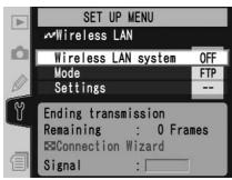
The status of the link between the server and the WT-2 is shown by the status LEDs and by the display in the top level of the wireless LAN menu.
The Status LEDs
The POWER LED lights when the WT-2 is receiving power from the camera. Signal quality is shown by the LINK LED: the faster the LED blinks, the better the signal and the faster data can be transmitted. The BUSY LED lights while data are being sent.

| Status | POWER | LINK | BUSY |
| Camera or exposure meters off, or Off selected for Wireless LAN > Wireless LAN system | (off) | (off) | (off) |
| Connecting to ftp server | (on) | (on) | (off) |
| Waiting to send data | (on) | (blinks) | (off) |
| Sending data | (on) | (blinks) | (on) |
| Connection error | (blinks) | (off) | (off) |
| WT-2 hardware malfunction | (blinks) | (blinks) | (blinks) |
The Status Display
Network status can also be viewed in the top level of the wireless LAN menu.
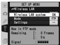
Status
The status of the connection between the server and the camera. “Now in FTP mode” is displayed when the camera is connected.

Now sending
The name of the file currently being sent.

Remaining
The estimated time required to send the remaining images (frames).

Signal
A five-level indicator of signal quality.

Error
Any errors that prevent the camera from connecting to the server.

Controlling the Camera: PTP/IP Mode
In PTP/IP mode, a camera equipped with a WT-2 can be controlled over a wireless network from a computer running Nikon Capture 4 version 4.2 or later (available separately) and photographs saved directly to the computer hard disk. Before the camera can be controlled from the computer, wireless settings must be adjusted appropriately and the camera and computer must be "paired" using special software. The principal steps involved in using PTP/IP mode for the first time are as follows:
1—Installing Pairing Software 39
2—Setup Using the Connection Wizard ..... 15–16
3—Pairing....17–19
4—Connecting to the Computer 20
5—Controlling the Camera....21
Steps 1–3 can be omitted once the WT-2 has been set up for connection to a particular computer.
Installing Pairing Software
The Wireless Connecting Utility supplied with the WT-2 must be installed on the host computer before it can be paired with the camera. See page 39 for more information.
Wireless Network Settings
For information on adjusting wireless network settings without using the Connection Wizard, see "Menu Guide" (26–31). See page 25 for information on loading settings files created with a computer.
Firewalls
PTP/IP mode uses UDP port 5353. It may be necessary to adjust firewall settings before connecting to a computer behind a firewall.
Setup Using the Connection Wizard
First-time setup can be completed with the help of the Connection Wizard. Make sure the network is active before starting. To prevent changes to settings from being lost should the camera monitor turn off automatically, use the optional AC adapter or choose the maximum camera monitor off delay.
1 Turn the camera on.
2 Check that Off is selected for Wireless LAN> Wireless LAN system in the camera setup menu 24).

3 Select PTP/IP for Wireless LAN>Mode (24).
4 In the top level of the wireless LAN menu, press the Ⓧ button to start the Connection Wizard. A list of available connections will be displayed. Press the multi selector up or down to highlight the desired connection and press the multi selector to the right to select it.
① Selected connection is marked with Ⓞ icon.
② Infrastructure connections are marked with ▲ icon, ad-hoc connections with 🔊 icon (27).
③ SS-ID (not displayed if SS-ID is unavailable).
Connection Not Available
If the desired connection is not listed, press the ⚙ button to search again. If the connection still can not be found, check settings on the network.
5 Press the ENTER button.

SS-ID
If prompted for an SS-ID, press the multi selector to the right and enter the connection SS-ID as described on page 26.

Encryption Key
If prompted for an encryption key, press the multi selector to the right and enter a key as described on page 27.
6 If the network is configured to supply an IP address automatically by DHCP server or Auto IP (51), press the multi selector to the right to select Obtain automatically. If the network requires a fixed IP address or subnet mask, enter the information supplied by the network administrator (28). Press the button to proceed to Step 7.
7 The dialog shown at right is displayed when setup is complete. Press the button to exit the wizard and return to the wireless LAN menu.
Errors
If an error is displayed, press the multi selector to the left and enter a valid setting. A "WIRELESS ERROR" or "TCP/IP ERROR" indicates that the associated options are set incorrectly. After checking settings for the host or access point, press the ⏻ button to restart the Connection Wizard and adjust camera settings to match.
Related Settings
To access advanced settings when entering data in steps 5–6, press the ⏻ button. The related section of the network settings menu will be displayed (💡 26–31).
Pairing
Once wireless network settings have been adjusted, the camera and computer must be “paired” before they can communicate in PTP/IP mode for the first time. “Pairing” allows the computer to control the camera by establishing permissions between the two devices.
1 Turn the camera on.
2 Select PTP/IP for the Wireless LAN>Mode option in the camera setup menu (💡 24).
3 Select On for Wireless LAN>Wireless LAN system (24).
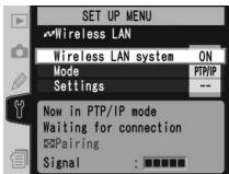
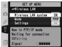
4 Confirm that "Now in PTP/IP mode/Waiting for connection" is displayed in the top level of the wireless LAN menu. For information on what to do if an error is displayed, see "Troubleshooting" (50).
5 Press the camera 📋 button. The message shown at right will be displayed, with the camera name in blue (💡 36).

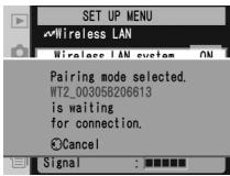
Pairing
The camera connection list (36) can store the names of up to ten computers (note that attempting to control the camera simultaneously from multiple computers may produce unexpected results; 21). When the connection list is full, computers can be deleted from the list to make room for additional pairings.
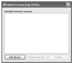
6 On the computer: Turn on the computer and start the Wireless Connecting Utility. Click Add device.
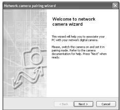
7 On the computer: Click Next.
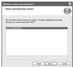
8 On the computer: A list of available cameras will be displayed. Select the desired camera and click Next.
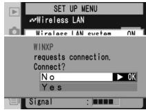
9 On the camera: A message will be displayed in the camera monitor stating that the computer is requesting a connection. Highlight Yes and press the multi selector to the right. The message "Connected to (computer name)" will be displayed when pairing is complete.
Mac OS X
Although the illustrations on these pages are taken from Windows XP, the pairing process for Mac OS X is identical to that described here.
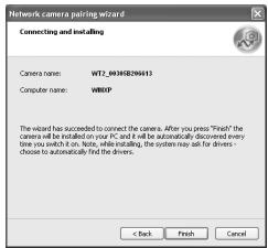
10 On the computer: Click Finish. If instructed to install a driver, follow the on-screen instructions to complete installation. If a dialog appears prompting you to select a program to perform an action, click Cancel.
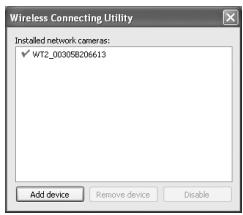
11 On the computer: A check mark will appear next to the camera name in the Wireless Connecting Utility window. Pairing is now complete; close the Wireless Connecting Utility.
The Wireless Connecting Utility Window
Installed network cameras: A list of the cameras with which the computer can pair.
Add device: Add a camera to the list of installed network cameras.
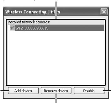
Remove device: Remove the selected device from the list of installed network cameras. To reconnect with this device, delete the computer from the camera connection list ⏻ 36) and repeat the pairing process.
Disable/Enable: Disable or enable the selected pairing.
Connecting to the Computer
1 Turn on a computer that has been paired with the camera (17) and wait for it to start up.
2 Turn the camera on.
3 Select PTP/IP for the Wireless LAN>Mode option in the camera setup menu (24).
4 Select On for Wireless LAN>Wireless LAN system (24).
5 Confirm that "Now in PTP/IP mode/Waiting for connection" is displayed in the top level of the wireless LAN menu. For information on what to do if an error is displayed, see "Troubleshooting" (50).
6 The connection is complete when the message, "Connected to (computer name)," is displayed in the pairing options menu. If the camera continues to display the "waiting for connection" message, repeat the steps described in "Pairing" (17).

Controlling the Camera
1 Complete the steps in "Connecting to a Computer" (20).
2 Start Nikon Capture 4 Camera Control on the host computer and confirm that PC is displayed in the camera's top control panel.
![P 125 F5.6 [ ] PC ( 45 )](/content/2020/05/116038/images/00bd12cc98f0af041bced8b6c95c078932cb6682f5a6c2fc00999f3bb215c4e0.jpg)
3 Control the camera as described in the Nikon Capture 4 User's Manual. Any photographs taken while the camera is connected will be recorded directly to the computer hard disk.
Loss of Signal During Transfer
A loss of signal may interrupt the connection while pictures are being transferred to Nikon Capture 4 Camera Control. If the POWER LED on the WT-2 is blinking ⏻ 22, select Off for the Wireless LAN>Wireless LAN system option in the camera setup menu and then select On again. Transfer will resume when the connection is re-established. Do not turn the camera off. Transfer can not be resumed once the camera is turned off.
Connecting to Multiple Computers
Any computer enabled in the connection list can connect to the camera when running Nikon Capture 4 Camera Control. Note, however, that attempting to control the camera simultaneously from multiple computers may produce unexpected results. Nikon recommends disabling the other connections if you are unsure whether the other computers in the connection list are running Nikon Capture 4 Camera Control (36).
Network Status
The status of the link between the computer and the WT-2 is shown by the status LEDs and by the display in the top level of the wireless LAN menu.
The Status LEDs
The POWER LED lights when the WT-2 is receiving power from the camera. Signal quality is shown by the LINK LED: the faster the LED blinks, the better the signal and the faster data can be transmitted. The BUSY LED lights when a connection is established.

| Status | POWER | LINK | BUSY |
| Camera or exposure meters off, or Off selected for Wireless LAN > Wireless LAN system | (off) | (off) | (off) |
| Connecting to computer | (on) | (on) | (off) |
| Waiting for connection; pairing possible | (on) | (blinks) | (off) |
| Connected; camera control possible | (on) | (blinks) | (on) |
| Connection error | (blinks) | (off) | (off) |
| WT-2 hardware malfunction | (blinks) | (blinks) | (blinks) |
The Status Display
Network status can also be viewed in the top level of the wireless LAN menu.
Status

The status of the connection between the computer and the camera. "Connected to (computer name)" is displayed when the camera is connected.
Signal

A five-level indicator of signal quality.
Error

Any errors that prevent the camera from connecting to the computer.
Menu Guide
This section describes the settings available for the Wireless LAN option in the camera setup menu when the WT-2 is connected.
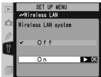
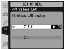
Wireless LAN system
Turn the WT-2 transceiver on or off.
| Option | Description |
| Off (default) | WT-2 receives no power from camera. Select this option to reduce drain on batteries. |
| On | WT-2 on; wireless communication possible. If ftp mode is selected, transmission of images marked with “send” icon begins immediately. |
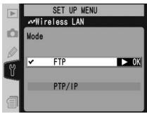
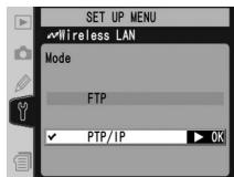
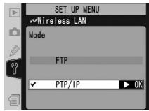
Mode
Choose FTP for ftp mode (💡 5), PTP/IP for PTP/IP mode (💡 14).

Settings
Adjust wireless network settings (💡 25–35), ftp settings (💡 37–38), or PTP/IP settings (💡 36).
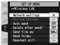
Network Settings
Adjust settings for connection to a wireless network or ftp server (26–35, or see page 42 for sample ftp settings). These settings can also be made with the help of the Connection Wizard (6, 14) or by loading a settings file that has been saved to the camera memory card with a computer (25). To prevent the
camera monitor from turning off while adjusting settings, set the Monitor off Custom Setting to 10m or use an optional EH-6 AC adapter to power the camera.
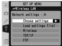
Choose Settings
Camera network settings are saved in one of four banks. Any changes to settings using the menus or Connection Wizard will be saved in the current bank, and are recalled when this bank is selected again.
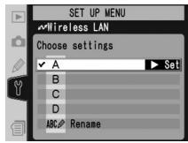
| Option | Description |
| A–D | Select bank. |
| Rename | Rename selected bank. |
Load Settings File
Load a network settings file that has been saved to the camera memory card using a computer.

| Option | Description |
| No (default) | Exit without changing settings. |
| Yes | Load Wireless, TCP/IP, and FTP settings from memory card. |

Creating a Settings File
An application for creating settings files is available from the websites listed on page 1 of this manual. After creating a settings file, save it to the root directory of the memory card using a CompactFlash card reader or PCMCIA memory card adapter. No more than one settings file should be stored on the memory card at a time. Additional information is available from the download site.
Wireless
Adjust settings for connection to a wireless network. The wireless menu has two pages of options; to scroll between pages, press the multi selector up or down.
![SET UP MENU Wireless LAN Wireless [1/2] SSID Communication mode Infrastructure Channel : --](/content/2020/05/116038/images/8bc740ccf831da5c13f7363040651944046840702ba6e0e815298476e71b1215.jpg)
Wireless Menu, Page 1/2
SSID: A BSS- or ESS-ID is required for connection to a wireless LAN adapter or access point. Leave this field blank to allow the network to set the SS-ID automatically ("any" connection). To change the BSS- or ESS-ID, highlight the current ID, press the multi selector to the right, and enter a new ID as described in the note below. Press 📋 to return to the wireless menu (1/2).
![SET UP MENU Wireless LAN Wireless [1/2] SSID Communication mode Infrastructure Channel : --](/content/2020/05/116038/images/acb67fd53cc5b3ba98c8afde0ed86eea5a288fb3f6907dde72ea8fd5252cb3d2.jpg)
Text Entry in the "Settings" Menu
If text entry is required to complete the selected setting, the following dialog will be displayed.
Keyboard area
Use multi selector to highlight letters, press center to select.
![SET UP MENU + cursor Input OK ! # $ % & ( ) * +, -. /0123456789: : = ?@ABCDEFGHIJKLMNOPQRSTUVWXYZ [ ] _ abc defghijklm](/content/2020/05/116038/images/fe3725ff469fc826c9f4e805f5b1c507850e307d06b2bf23e83340fed6e5ff37.jpg)
Text display area
Text appears in this area. To move cursor, press ☐ while using up, down, left, and right buttons on multi selector.
Use the multi selector to highlight the desired character in the keyboard area and press the center of the multi selector to insert the highlighted character at the current cursor position. To delete the character under the cursor, press the 📋 button. To move the cursor to a new position, press the ⏻ button while using the multi selector. No more than thirty-two characters can be entered; if additional characters are entered when the display is full, all characters after the thirty-third will be deleted.
To complete entry and return to the previous menu, press the ENTER button. To exit to the setup menu without completing text entry, press MENU.
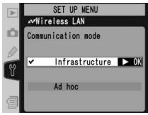
Communication mode: Choose a mode according to how the wireless network is set up.
| Option | Description |
| Infrastructure (default) | Connection to wireless network is via access point. |
| Ad-hoc | Direct peer-to-peer wireless connection to host using IEEE 802.11b standard (IEEE 802.11g is not available in this mode). |
Channel\*
1

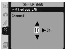
Choose channel. ^†
2

![SET UP MENU Wireless LAN Wireless [1/2] SSID Communication mode Ad hoc Channel : 10](/content/2020/05/116038/images/d04a77c5052fabf816e0ff7ab60962f9001040c758df5c5b4d0e61c78fa029c4.jpg)
Return to wireless menu (1/2).
* Not required if Infrastructure is selected for Communication mode.
† The WT-2 offers a choice of thirteen channels (1–13), the WT-2A a choice of eleven channels (1–11).
Wireless Menu, Page 2/2
Encryption
1

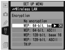
Highlight encryption method.
2

![SET UP MENU Wireless LAN Wireless [2/2] Encryption WEP: 64-bit, base *****...](/content/2020/05/116038/images/2be288ce4e7fb6020a8d0992ac446685ec862e6e6dd4413405d389b446606dec.jpg)
Return to wireless menu (2/2).
3

![SET UP MENU Wireless LAN Wireless [2/2] Encryption WEP: 64-bit, base 16 *****.](/content/2020/05/116038/images/e52ce17fa8f3089a96525df966bddefade1eac402af87826bb50f74f6c4c1e8e.jpg)
Highlight encryption key.
4

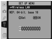
Edit encryption key:
- Base 16: press multi selector left or right to select character, up or down to change. 64-bit keys are 10 digits long, 128-bit keys 26 digits long.
- ASCII/TKIP: enter key as described on page 26. 64-bit keys are 5 characters long, 128-bit keys 13 characters long, TKIP keys 8 to 64 characters long.
5

![SET UP MENU Wireless LAN Wireless [2/2] Encryption WEP: 64-bit, base 16 *****.](/content/2020/05/116038/images/37178913d97e744246dbdee22291950082e10028f0c1230b5a42e72e7ed822b6.jpg)
Return to wireless menu (2/2).
TCP/IP
Adjust TCP/IP settings as described on the following pages. The TCP/IP menu has three pages of options; to scroll between pages, press the multi selector up or down.
![SET UP MENU Wireless LAN TCP/IP [1/3] Obtain automat: Set Address : 000.000.000.000 Mask : 255.255.255.000](/content/2020/05/116038/images/26145c73d0903c2da4586cfab8b5f241b694b3f90d65fa5768677d71486972c2.jpg)
TCP/IP Menu, Page 1/3
Obtain automatically: Highlight this option and press the multi selector right to toggle it on (✓) or off. Turn this option on if the wireless network is configured to supply an IP address automatically by DHCP server or Auto IP (51). Otherwise turn it off and enter the address and subnet mask supplied by the network administrator as described on the following page.
![SET UP MENU Wireless LAN TCP/IP [1/3] Obtain automat: Set Address : 000.000.000.000 Mask : 255.255.255.000](/content/2020/05/116038/images/fb9f91af6b3a6baa0f073c091fee15e2e07cfe79f839245e6a4f53b7f7d58557.jpg)
1

![SET UP MENU Wireless LAN TCP/IP [1/3] Obtain automatically Address : 000.000.000.0 Mask : 255.255.255.000](/content/2020/05/116038/images/76abbdee2a409d307f5bf40aeb82f402437f3da2928a0316251f18fa3cfd69dd.jpg)
Highlight Address.
2

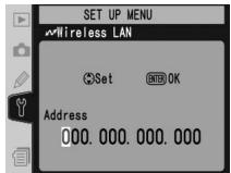
Enter edit mode.
3

Press multi selector left or right to select, up or down to change.
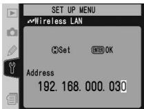
4

![SET UP MENU Wireless LAN TCP/IP [1/3] Obtain automatically Address : 192.168.000.0 Mask : 255.255.255.000](/content/2020/05/116038/images/18672005b8698f72a4983576db916501693d66cf81fb1dc139dc384e1c6a46f0.jpg)
Exit to TCP/IP menu (1/3). If subnet mask is required, proceed to Step 5.
5

![SET UP MENU Wireless LAN TCP/IP [1/3] Obtain automatically Address : 192.168.000.030 Mask : 255.255.255.0](/content/2020/05/116038/images/859bea6593ffe45a2e721beee5b984ada23985eb9344311b99e9921f41070ffa.jpg)
Highlight Mask.
6

Enter edit mode.
7

Choose subnet mask.
8

![SET UP MENU Wireless LAN TCP/IP [1/3] Obtain automatically Address : 192.168.000.030 Mask : 255.255.255.0](/content/2020/05/116038/images/81cff67433919ef4276266f90ce10ee99e743946ec1b7edf4f11ff30f112f2a9.jpg)
Exit to TCP/IP menu (1/3).
TCP/IP Menu, Page 2/3
Use gateway: Highlight this option and press the multi selector right to toggle it on (√) or off. If the network requires a gateway address, turn this option on and enter the address supplied by the network administrator as described below.
![SET UP MENU Wireless LAN TCP/IP [2/3] □ Use gateway ▶ Set Address : 000.000.000.000 □ Enable DNS Address : 000.000.000.000](/content/2020/05/116038/images/2a950918a191b6c7396b9e61afd3ca0354c1ae1a7133c0aef504db6863e73d63.jpg)
1

![SET UP MENU Wireless LAN TCP/IP [2/3] Use gateway Address : 000,000,000.0 Enable DNS Address : 000,000,000.000](/content/2020/05/116038/images/89897368f4f0289636c621c7a298b809dec8cdbc08e25af6e5f868b39286b2b8.jpg)
Highlight Address.
2


Enter edit mode.
3

Press multi selector left or right to select, up or down to change.
4

![SET UP MENU Wireless LAN TCP/IP [2/3] Use gateway Address : 255.255.255.0 Enable DNS Address : 000.000.000.000](/content/2020/05/116038/images/c66fc6121d8796cd5c853c573c8e111b2bdd60d9531ca878ab81857b67ed3e6e.jpg)
Return to TCP/IP menu (2/3).
Enable DNS: Highlight this option and press the multi selector right to toggle it on (√) or off. If a Domain Name Server (DNS) exists on the network, turn this option on and enter the address supplied by the network administrator as described below.
![SET UP MENU Wireless LAN TCP/IP [2/3] Use gateway Address : 255.255.255.000 Enable DNS Set Address : 000.000.000.000](/content/2020/05/116038/images/befc0b94659db9be315c074dd93cc4db4324ad1edd2c945e65d7f0122ea5724e.jpg)
1

![SET UP MENU Wireless LAN TCP/IP [2/3] Use gateway Address : 255,255,255.000 Enable DNS Address : 000.000.000.0](/content/2020/05/116038/images/b5f84e06af7e86546a66fe5400b4a7b8176c088886350d36787190b3db4c2e4f.jpg)
Highlight Address.
2

Enter edit mode.
3

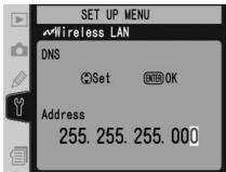
Press multi selector left or right to select, up or down to change.
4

![SET UP MENU Wireless LAN TCP/IP [2/3] Use gateway Address : 255.255.255.000 Enable DNS Address : 255.255.255.0](/content/2020/05/116038/images/921f75f4fe8c2083a2fff65ca66f2de0f2391a74ec62f0dd5cbfef85c64c9ffe.jpg)
Return to TCP/IP menu (2/3).
TCP/IP Menu, Page 3/3
MAC address: This field lists the twelve-digit Media Access Control (MAC) address for the WT-2.
![SET UP MENU Wireless LAN TCP/IP [3/3] MAC address 00-30-58-20-66-13](/content/2020/05/116038/images/91409d31d0eb75b067d7cf1019ff7f4aa03a144689c844e9b0d79f54a538f52e.jpg)
FTP (FTP Mode Only)
Adjust ftp settings as described on the following pages. The ftp menu has four pages of options; to scroll between pages, press the multi selector up or down.
![SET UP MENU Wireless LAN FTP [1/4] Server Address : 192.168.0.30 Port : 21 □ PASV mode](/content/2020/05/116038/images/f9a604d72b77bc7c3009b0a1f4ec0fd3de83542a832473fe9197e0694b6fe08e.jpg)
FTP Menu, Page 1/4
Server
1

![SET UP MENU Wireless LAN FTP [1/4] Server Address : Port : 21 □ PASV mode](/content/2020/05/116038/images/a1f5b6219edfa554ae9b4bdda285537374facf1ad20acbcdc7a060fba2f7536e.jpg)
Highlight Address.
2

![SET UP MENU + cursor Input ENTER OK ! '# $% & ( ) * +, -. /0123456789: : < = ? ? @ A B C D E F G H I J K L M N O P Q R S T U V W X Y Z [ ] _ a b c d e f g h i j k l m n o p q r s t u v w x y z { }](/content/2020/05/116038/images/06dc919ffc45b209048ea87734ef23c619774f5cc7d8582f4e2a46fe59dc957f.jpg)
Display text entry dialog (26).
3

![SET UP MENU Wireless LAN FTP [1/4] Server Address : 192.168.0.30 Port : 21 PASV mode](/content/2020/05/116038/images/674c2bddefeb2e3c28772b9f99cf0c07050323809873ef7f11d87f9230813a79.jpg)
Enter URL or IP address of ftp server (if unsure of correct address, contact server administrator). Press ENTER button to return to ftp menu (1/4). If port number is required, proceed to Step 4.
4

![SET UP MENU Wireless LAN FTP [1/4] Server Address : 192.168.0.30 Port : 21 □ PASV mode](/content/2020/05/116038/images/2ef3eb294d0b63ea350847e679397097782e067132448ec05fb8e0ab55bf9f78.jpg)
Highlight Port.
5

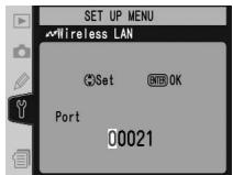
Enter edit mode.
6

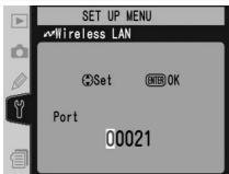
Press multi selector left or right to select, up or down to change.
7

![SET UP MENU Wireless LAN FTP [1/4] Server Address : 192.168.0.30 Port : 21 □ PASV mode](/content/2020/05/116038/images/c59447f20803f9c4b7d5929a156856c6d53a895def15966ae6751ef13997567f.jpg)
Return to ftp menu (1/4).
PASV mode: Highlight this option and press the multi selector right to toggle PASV mode on (√) or off. Turn this option off to use normal (PORT) mode. Be sure the server supports PASV mode before turning this option on.
![SET UP MENU Wireless LAN FTP [1/4] Server Address : 192.168.0.30 Port : 21 □ PASV mode ▶ Set](/content/2020/05/116038/images/278d34fc46eb9e18b6aac4c04bd49fabd07377c7fa7f0f3594b5f7a4d9a33fff.jpg)
FTP Menu, Page 2/4
Anonymous login: Highlight this option and press the multi selector right to toggle it on (✓) or off. Turn this option on for anonymous login, off to enter a user name and password as described below.
![SET UP MENU Wireless LAN FTP [2/4] Anonymous login Set User ID Password *****...](/content/2020/05/116038/images/482b529ce7d33e9cd07376936fd7e4c3a0c65112a9a5342dbb0989b63e66fd51.jpg)
1

![SET UP MENU Wireless LAN FTP [2/4] Anonymous login User ID Password *****...](/content/2020/05/116038/images/42c38a22cf2a9bbe908aed4915b6d81188682ddf4ea4205cd1e613ccc2cb08ec.jpg)
Highlight User ID.
2

Display text entry dialog (26).
![SET UP MENU + cursor INPUT ENTER OK ! ' # $ % & ' ( ) * +, -. /0123456789 : : < = ??@ABCDEFGHIJKLMNOPQRSTUVWXYZ [ ] _abcdefghijklmnopqrstuvwxyz { } nopqrstuvwxyz { }](/content/2020/05/116038/images/39fb54be436284f698aa8e9ced5625925f3d57d760acfa8e7288d1e3d86e94ca.jpg)

26).
3 Enter user name for login to ftp server and press ENTER button to return to ftp menu (2/4).
4

Highlight Password.
![SET UP MENU Wireless LAN FTP [2/4] Anonymous login User ID anonymous Password *****...](/content/2020/05/116038/images/cfa48b9e3cdae2ef199e2a8e2180e32c597da87a8f891b995afc37e5c3ee11e9.jpg)
5

Display text entry dialog (26).
![SET UP MENU + cursor INPUT ENTER OK ! ' # $ % & ' ( ) * +, -. /0123456789 : : < = ??@ABCDEFGHIJKLMNOPQRSTUVWXYZ [ ] _abcdefghijklmnopqrstuvwxyz { } nopqrstuvwxyz { }](/content/2020/05/116038/images/91382255a907a5db709a1d3975ebdba49076a8df4290f5f486871c136e0c9314.jpg)

26).
6

![SET UP MENU Wireless LAN FTP [2/4] Anonymous login User ID anonymous Password *****...](/content/2020/05/116038/images/f1ce197d2ca5063e6bea4cabc782c227210e53a42daeccbddadc2238344c50e0.jpg)
After entering password for login to ftp server, press ENTER button to return to ftp menu (2/4). Password is disguised as row of dots.
FTP Menu, Page 3/4
Use home folder: Highlight this option and press the multi selector right to toggle it on (✔) or off. Turn this option on to upload files to the server's default "home" folder, off to specify a directory as described below.
![SET UP MENU Wireless LAN FTP [3/4] Home folder Set Folder](/content/2020/05/116038/images/e9614e8335226ebac7ede9cbb80108b816e915e88daeffa9682ed6c70d7fc805.jpg)
1

![SET UP MENU Wireless LAN FTP [3/4] Home folder Folder](/content/2020/05/116038/images/1482c915eb9c43616ac0e55b7dca3d50a4ae8f206ec2152180fce73c449eb449.jpg)
Highlight Folder.
2

Display text entry dialog (26).
![SET UP MENU + cursor Input ENTER OK ! ' # $ % & ' ( ) * +, -. /0123456789 : : < = ??@ABCDEFGHIJKLMNOPQRSTUVWXYZ [ ] _abcdefghijklmnopqrstuvwxyz { } nopqrstuvwxyz { }](/content/2020/05/116038/images/3e25057c6d645f50fff476f21121f633afa1c1963091277a88ab0c5e17873cdc.jpg)

26).
3

![SET UP MENU Wireless LAN FTP [3/4] Home folder Folder WT-2](/content/2020/05/116038/images/3bcb65e5e97869075995879750ae18f6f5df8fd1f64e84abea6d35c8b1d6bd5e.jpg)
After entering name of destination folder on ftp server, press ENTER button to return to ftp menu (3/4).

Home Folder
On a Windows ftp server, the home folder is the same as the home directory (45). On a Macintosh, the home folder is the root directory of the user folder for the current account.
FTP Menu, Page 4/4
Use proxy server: Highlight this option and press the multi selector right to toggle it on (√) or off. If a proxy server is required for ftp, turn this option on and enter an address and port number as described below.
![SET UP MENU Wireless LAN FTP [4/4] □ Use proxy serve ▶ Set Address : Port : 8080](/content/2020/05/116038/images/a53a0849988850716deb4b628c97acc8ea6dc24f21c48338f93bbff376713701.jpg)
1

![SET UP MENU Wireless LAN FTP [4/4] Use proxy server Address : Port : 8080](/content/2020/05/116038/images/c345ba80e2078713c12046670fae8aae8521a66e74ab9218ba27f7935cf9ba6f.jpg)
Highlight Address.
2

Display text entry dialog (26).
![SET UP MENU + cursor Input ENTER OK ! ' # $ % & ' ( ) * +, -. /0123456789 : : < = ??@ABCDEFGHIJKLMNOPQRSTUVWXYZ [ ] _abcdefghijklmnopqrstuvwxyz { } nopqrstuvwxyz { }](/content/2020/05/116038/images/7415296ba21f285aaa35620f6612e45b1f934dd66060fce9368f48e6d1b4b5b6.jpg)

26).
3
Enter proxy server address and press ENTER button to return to ftp menu (4/4).
4

![SET UP MENU Wireless LAN FTP [4/4] Use proxy server Address : 192.168.1.254 Port : 8080](/content/2020/05/116038/images/695f7263554980ba7a385c0ec55d17dc076ceb68945235a04ba06f51800da550.jpg)
Highlight Port.
5

Enter edit mode.
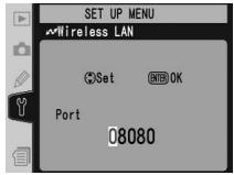
6

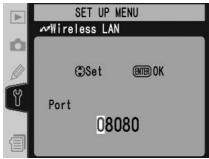
Press multi selector left or right to select, up or down to change.
7

![SET UP MENU Wireless LAN FTP [4/4] Use proxy server Address : 192.168.1.254 Port : 8080](/content/2020/05/116038/images/de29ce8afba810fe32dd53c8ed42bc3c802b7e77bfed678b7c3493757edc3b49.jpg)
Return to ftp menu (4/4).
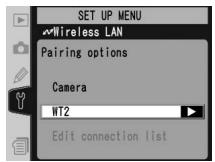
Pairing Options (PTP/IP Mode Only)
This menu offers the following pairing options (for more information on pairing, see page 17):
Camera
The name under which the camera is registered when paired with a computer. The default name is "WT2_" followed by the MAC address of the WT-2. To use a different name, highlight the current name in the pairing options menu, press the multi selector to the right, and edit the name as described on page 26. The maximum length is thirty-nine characters.
Edit Connection List
Selecting this option displays the computers with which the camera is paired. To enable or disable a pairing with a selected computer or delete computers from the list, highlight the computer name and press the multi selector to the right. The menu shown at right will be displayed.
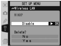
| Option | Description |
| Enable | Enable pairing with selected computer. |
| Disable | Disable pairing with selected computer. |
| Delete | Select Yes to delete selected computer from connection list. Camera can not be used with computer in PTP/IP mode until camera has been removed from list of installed network cameras in Wireless Connecting Utility (19) and pairing performed again. |
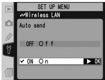
Auto Send (FTP Mode Only)
Choose whether to upload photographs to the server as they are taken.
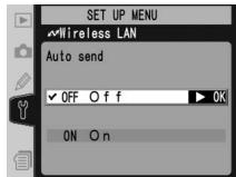
| Option | Description |
| Off (default) | Photos are not automatically uploaded to server as they are taken. Photos can be selected for transmission when camera is in playback mode. |
| On | Photos are uploaded immediately after being recorded to camera memory card.* Be sure memory card is inserted in camera before shooting. |
* Pictures will not be uploaded to the server if Off is selected in the Wireless LAN>Wireless LAN system menu. Pictures will instead be marked with a "send" indicator as they are recorded to the memory card.
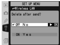
Delete After Send (FTP Mode Only)
Select On to delete photographs from the camera memory card automatically after they have been successfully uploaded to the server (the default option is Off). Files that were uploaded before this option was selected are not affected. Photographs will not be deleted while displayed in slide shows or in the delete, print set, and preset white balance menus. Sequential file numbering is used while this option is in effect, regardless of the option selected for the File No. Seq. Custom Setting.
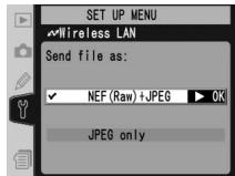
Send File As (FTP Mode Only)
When uploading NEF+JPEG images to an ftp server, choose whether to send both NEF (RAW) and JPEG files or only the JPEG files.
| Option | Description |
| NEF (Raw) + JPEG (default) | Upload both NEF (RAW) and JPEG files. JPEG files are sent first. |
| JPEG only | Upload JPEG files only. |
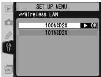
Send Folder (FTP Mode Only)
All files in the selected folder (including those already marked as "sent") will be uploaded in ascending order by file number, beginning when the folder is selected. The folder itself will not be uploaded. This option is not available when the memory card contains no folders.
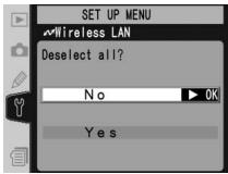
Deselect All (FTP Mode Only)
Select Yes to remove "send," "sending," and "sent" marking from all images on the memory card. Upload of any images marked with a "sending" icon will immediately be terminated.
Appendices
Installing Pairing Software
This section describes how to install the pairing software supplied with the WT-2 (17). This software is required when using the WT-2 in PTP/IP mode (14).

Supported Operating Systems
This software requires Mac OS X version 10.3 or later or preinstalled versions of Windows XP Professional or Windows XP Home Edition.
Installation (Windows XP)
1 Start the computer and log in to an account with administrator privileges.
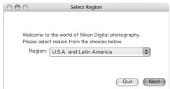
2 Insert the supplied installer CD in a CD-ROM drive. The "Select Region" dialog will be displayed; select a region and click Next.
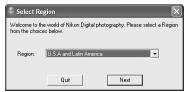

If the "Select Region" Dialog Is Not Displayed
If the "Select Region" dialog is not displayed, select My Computer from the Start menu and double-click the icon for the CD-ROM drive containing the installer CD.
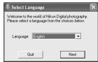
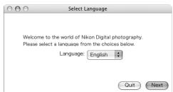
3 Select a language and click Next.
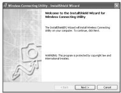
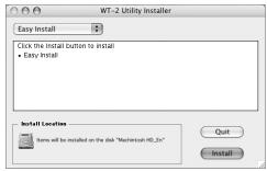
4 Click Easy Install.
5 Click Next.

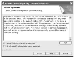
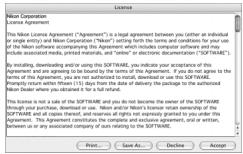
6 A license agreement will be displayed. After reading the agreement, select I accept the terms in the license agreement and click Next to accept and proceed with installation.
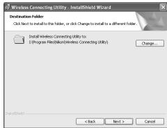
7 The default install location is displayed. Click Next to install the software to this folder. To choose another folder, click Change... and navigate to the desired location.
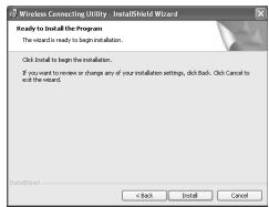
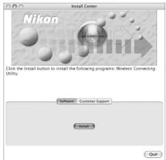
8 Clicking Next in Step 7 displays the dialog shown at right. Click Install.
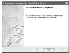
9 Click Finish.
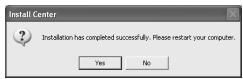
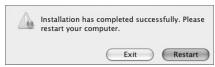
10 Click Yes to restart the computer.
Installation (Mac OS X)
1 Start the computer and log in to an account with administrator privileges.
2 Insert the supplied installer CD in a CD-ROM drive. Double-click the installer CD icon on the desktop, and then double-click the Welcome icon.
3 The "Select Region" dialog will be displayed. Select a region and click Next.
4 Select a language and click Next.
5 Click Install.
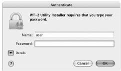
6 Enter the administrator name and password and click OK.
7 A license agreement will be displayed. After reading the agreement, click Accept to accept its terms and proceed with installation.
8 Click Install.
9 Click Yes to add the Wireless Connecting Utility to the Dock, No to proceed without adding it to the Dock.

10 Click Quit.
11 Click Restart to restart the computer.
Sample ftp Settings
The following pages describe how to set up a simple infrastructure network using the WT-2 and a Windows XP Professional ftp server. Encryption and network security are not discussed.
1—Preparation.... 42
2—Building a Network.... 43
3—Configuring the Server 43–45
4—Configuring the Wireless LAN Adapter ..... 45
5—Configuring the WT-2....46–47
6—Uploading Pictures....48–49
Preparation
Ready the following items:
- D2X digital camera
- ftp server ^1
^1 Windows XP Professional computer with Internet Information Services (IIS) installed.
^2 Bridge type. Additional settings may be required when using wireless router. See documentation provided by manufacturer for details.
Building a Network
Configure the network as shown below. In this example, the wireless LAN access point is connected by a cable to the server, and the server is not connected to any other network devices.
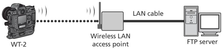
flowchart
graph LR
    A["WT-2"] -->|Wireless LAN access point| B["LAN cable"]
    B --> C["FTP server"]
Configuring the Server
The following example assumes that Windows XP Professional and Internet Information Services (IIS) are already installed (IIS is included in the standard install of Windows XP Professional; for more information, contact Microsoft). Be sure to use characters supported by the WT-2 📋 26) when specifying such settings as user ID, password, and folder names.
Entering an IP Address
Open the Network and Internet Settings>Network Connections control panel. Right-click the Local Area Connection icon and select Properties from the menu that appears.
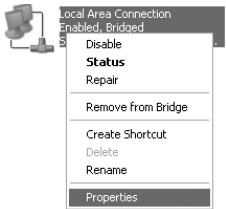
Select Internet Protocol (TCP/IP) and click Properties to display the "Internet Protocol (TCP/IP)" dialog. Enter an IP address and subnet mask for the ftp server.
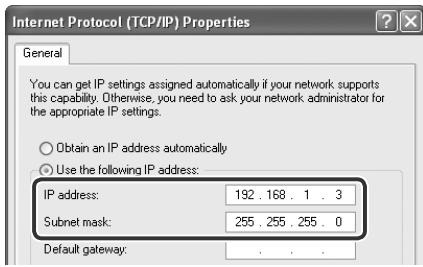
In this example, it is assumed that network uses class C private IP addresses and subnet masks. Be sure IP address differs from addresses assigned to wireless LAN adapter and WT-2. For example, if ftp server is assigned 192.168.1.3, 192.168.1.1 can be assigned to adapter and 192.168.1.2 to WT-2. All addresses must be in same class.
Creating an FTP Site
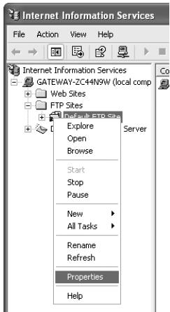
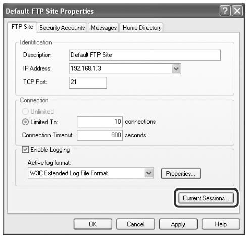
Go to the Performance and Maintenance>Administrative Tools control panel and open the Internet Information Services console. Right-click the Default FTP site folder and choose Properties from the menu that appears. In the “Default FTP Site Properties” dialog, open “FTP Site” and enter a TCP Port number. The port number is normally 21.

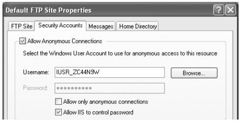
Open “Security Accounts” and select Allow Anonymous Connections and Allow IIS to control password. Make sure the default user ID (composed of “IUSR” plus the computer name) is unchanged and leave the password field blank.
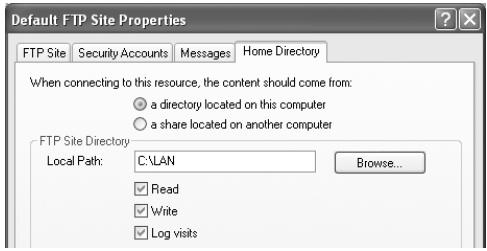
Next, open "Home Directory" and select A directory located on this computer. The root directory for images uploaded to the ftp server is listed in the Local Path text box; choose a folder and check Read, Write, and Log visits.
Before proceeding to the next step, click OK to close the properties dialog.
Configuring the Wireless LAN Adapter
The minimum information needed to configure a wireless LAN adapter is listed below. Contact the manufacturer for details.
| Wireless mode | 802.11b or 802.11g |
| SS-ID ^1 | D2X |
| Encryption (WEP) | Off |
| "Any" connection ^2 | Disabled |
| Channel | Any |
| IP address ^3 | Obtain IP address automatically: OffIP address: 192.168.1.1Subnet mask: 255.255.255.000 |
| Default gateway | 000.000.000.000 |
| DNS | 000.000.000.000 |
| MAC address ^4 | Unspecified |
^1 Same SS-ID must be assigned to WT-2.
^2 Not required if adapter does not support “any” connection.
^3 In this example, it is assumed that network uses class C private IP addresses and subnet masks. Address assigned to adapter must differ from addresses of server and WT-2. For example, if ftp server is 192.168.1.3, 192.168.1.1 can be assigned to adapter and 192.168.1.2 to WT-2. All addresses must be in same class.
^4 If MAC address is required, enter MAC address for WT-2 (☐ 31).
Configuring the WT-2
Before adjusting network settings as shown below, select Off in the Wireless LAN > Wireless LAN system menu.

Wireless
| SSID1 | D2X |
| Communication mode | Infrastructure |
| Channel | — |
| Encryption | None |
^1 Same SS-ID must be assigned to wireless LAN adapter.
TCP/IP
| IP address1 | Obtain automatically: OffAddress: 192.168.1.2Mask: 255.255.255.000 |
| Gateway | Use gateway: Off |
| DNS | Enable DNS: Off |
^1 In this example, it is assumed that network uses class C private IP addresses and subnet masks. Address assigned to WT-2 must differ from addresses of server and wireless LAN adapter. For example, if ftp server is 192.168.1.3, 192.168.1.1 can be assigned to adapter and 192.168.1.2 to WT-2. All addresses must be in same class.
FTP
| Server | Address: 192.168.1.3 ^1 Port: 21 |
| PASV mode | Off |
| Anonymous login | On |
| User ID | |
| Password | |
| Home folder ^2 | On |
| Folder | |
| Use proxy server | Off |
^1 Enter address assigned ftp server (☐ 44).
^2 Photographs are uploaded to folder selected in "Home Directory" tab of "Default FTP Site Properties" dialog (45).
Uploading Pictures
This section describes how to upload pictures as they are taken. For best results, the WT-2 and wireless LAN adapter should be within a few meters with no obstacles between them.
1 Set the Wireless LAN>Mode option in the camera setup menu to FTP and select On for Wireless LAN>Wireless LAN system.
2 Confirm that a connection has been established. To check the connection from the camera, confirm that "Now in FTP mode" is displayed in the top level of the wireless LAN menu. For information on what to do if the camera shows "WIRELESS ERROR," "TCP/IP ERROR," or "FTP ERROR," see "Troubleshooting" (50).
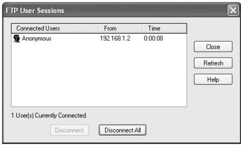
To check the status of the connection from the computer, right-click the Default FTP site folder and select Properties from the menu that appears. Open “FTP Site” and click Current Sessions....
Confirm that "Anonymous" is listed under "Connected Users." For information on what to do if no connection is listed, see "Troubleshooting" (50).
3 Select On for Wireless LAN>Auto send. Take a picture and confirm that the image has been uploaded to the specified folder on the ftp server.
Troubleshooting
| Problem | Solution | |
| “POWER” LED does not light. | Turn camera on.Press shutter-release button halfway to activate exposure meters.SelectOnforWireless LAN>Wireless LAN systemoption in camera setup menu.Reattach WT-2. | 5—244 |
| All LEDs blink at once. | WT-2 hardware error. Contact a Nikon-authorized service representative. | — |
| Wireless LANoption not available in camera setup menu. | SelectPTPforUSBoption in camera setup menu. | 5 |
| Excessive radio interference. | Change orientation of camera or antenna. | — |
| Camera displays wireless, TCP/IP, or FTP error. | Check settings for host and/or wireless LAN adapter and adjust camera settings appropriately. | 262832 |
| Can not connect to ftp server. | Check settings for server and/or wireless LAN adapter and adjust camera settings as described in “Sample ftp Settings.” | 42 |
| Transfer interrupted before all photographs are sent. | Transfer will resume if camera is turned off and then on again, exposure meters are reactivated, orOnforWireless LAN>Wireless LAN systemoption in camera setup menu. | 11 |
Glossary
Ad-hoc
Devices in an ad-hoc wireless network communicate directly ("peer to peer"), without a wireless access point. The WT-2 supports an ad-hoc mode for direct wireless connection to a computer or ftp server.
"Any" connection
Allows devices to connect to wireless network without an SS-ID. Can be used for wireless “hot spots” but is not as secure as connections that require an SS-ID.
Auto IP (APIPA—Automatic Private IP Addressing)
Allows devices in a network to automatically assign themselves unique IP addresses if no DHCP server is found on the network. Auto IP uses addresses from 169.254.1.0 to 169.254.254.255 and a subnet mask of 255.255.0.0. These addresses are neither global nor private but are reserved for Auto IP.
BSS-ID (Basic Service Set ID)
All wireless devices on an ad-hoc wireless network share the same BSS-ID. The BSS-ID may be up to thirty-two characters long and is case sensitive. See also Ad-hoc.
Channel
When multiple wireless LANs with different ESS-IDs are operating on a single frequency within a given area, transmission speeds will drop. Specifying a separate channel (frequency) for each network can prevent interference and increase transmission speeds (note that all devices in the same network must be set to the same channel). In the IEEE 802.11b/g standard, the 2.4 GHz band is divided into 14 channels, each separated by 4 MHz.
DHCP (Dynamic Host Configuration Protocol) Server
Each device in a TCP/IP network requires an IP address. If a DHCP server is present on the network, IP addresses will be assigned automatically. A DHCP server will not be present on networks that consist solely of Windows Me, Windows 98, or Windows 95 computers. DHCP may be enabled on other networks; consult the network administrator or see the manual provided with the router or operating system.
DNS (Domain Name Server)
A server that contains a database of IP addresses and host names for the machines it administers and that converts host names to IP addresses in response to queries from clients. Each DNS can also query other Domain Name Servers for addresses not listed in its database.
ESS-ID (Extended Service Set ID)
Multiple BSSs can be configured to form an ESS, allowing users to roam between wireless access points. Only devices with the same ESS-ID as a given access point can communicate with that access point. The ESS-ID may be up to thirty-two characters long and is case sensitive.
Gateway
A network node that acts as an entrance to another network, for example between a company network and the Internet.
IIS (Internet Information Services)
Microsoft's name for its Web server software. Notable for its close connection to Windows-based systems through Active Server Pages (ASPs). When installed as part of the operating system, IIS makes it relatively easy to build web a server.
Infrastructure
Devices in an infrastructure network communicate via one or more wireless access points. The WT-2 supports an infrastructure mode for connection to a wireless network via an access point.
IP address
Address given to each node in a TCP/IP network. All nodes in a TCP/IP network must have a unique IP address. Private IP addresses are recommended for nodes that are part of a local network.
LAN (Local Area Network)
A network of computers located in relatively close proximity to one another. LANs generally support data transfer speeds of 10–100 Mbps.
MAC (Media Access Control) Address
A unique hardware address for each device on a network, required when sending and receiving packets.
PASV mode
PASV mode is used by clients behind firewalls, when it allows the ftp server to supply the port number.
Private IP address
An IP address that is only visible within a local network. Because packets using a private IP address can not be transmitted to another network, they are usually sent between networks via a proxy server or NAT. Private IP addresses in the range 10.0.0.0–10.255.255.255 are termed “class A.” Class B addresses are in the range 172.16.0.0–172.31.255.255, class C addresses in the range 192.168.0.0–192.168.255.255. The class of address used depends on the size of the network. Class C addresses are often used for small networks.
Protocol
A set of rules for passing information back and forth between devices in a network. By defining such elements of communication as how links are established, how receipt of a signal is acknowledged, how data are encoded, and how to handle errors, a protocol ensures that data are transmitted without loss of information.
Proxy
A server that stands between large networks and local networks or computers, typically to ensure security. One element of a firewall.
PTP/IP (Picture Transfer Protocol over Internet Protocol)
An image transfer for transmitting images over wireless LANs. It represents an extension to the Picture Transfer Protocol (PTP) used to transfer images between cameras and computers connected via USB cable.
SS-ID (Service Set ID)
An SS-ID prevents interference between devices in different networks. See BSS-ID, ESS-ID.
Subnet mask
A mask that divides a network into subnets.
TCP/IP (Transmission Control Protocol/Internet Protocol)
A dual protocol consisting of a transport-layer protocol (TCP) that divides data into packets which it later reassembles, and a network protocol (IP) that handles transmission of the packets between points in the network. It can be implemented on different platforms, allowing data to be transmitted between machines with different operating systems.
TKIP (Temporal Key Integrity Protocol)
An encryption method which uses dynamic keys that change periodically or after a specified amount of data have been transmitted, making it more secure that WEP, which uses fixed keys.
UDP (User Datagram Protocol)
A fast but unreliable transport layer transmission protocol using the DSI model.
USB (Universal Serial Bus)
A standard for connecting peripheral devices. USB supports data transfer rates of up to 480 Mbps (USB 2.0). Devices connected via USB can be connected and disconnected with the power on (“hot plug”) and do not require separate IRQ (interrupt request) numbers, preventing conflicts with other devices.
WEP (Wired Equivalent Privacy)
A privacy protocol intended to provide users of wireless networks with the same level of privacy as a wired network. When using WEP, enter the encryption key provided by the network administrator.
Wireless LAN access point
A wireless transceiver that acts as the connection between wireless devices and a wireless network.
Specifications
| Standards | IEEE 802.11b/g (standard wireless LAN protocol), ARIB STD-T66 (standard for low power data communications systems) |
| Communication protocols | IEEE 802.11g: OFDMIEEE 802.11b: DBPSK, DQPSK, CCK |
| Range (line of sight) | Approximately 30 m (98') with WA-S1 standard antennaApproximately 150 m (492') with WA-E1 extended range antenna and large antenna at wireless LAN access point |
| Operating frequency | WT-2: 2412–2472 MHz (13 channels)WT-2A: 2412–2462 MHz (11 channels) |
| Data rates* | IEEE 802.11g: 6, 9, 12, 18, 24, 36, 48, and 54 MbpsIEEE 802.11b: 1, 2, 5.5, and 11 Mbps |
| Security | TKIP, 128/64-bit (104/40-bit) WEP |
| Access protocols | Infrastructure/ad-hoc |
| Current consumption | Sleep: 200 mA maximum (at input voltage of 13.5 V)Send: 250 mA maximum (at input voltage of 13.5 V) |
| Power consumption | 3.4 W maximum |
| Operating environment | Temperature: 0–40 °C (32–131 °F)Humidity: less than 85% (no condensation) |
| Weight | 210 g/7.4 oz (excluding antenna) |
| Dimensions (W × H × D) | 146.5 mm × 34.5 mm × 65.5 mm (5.8" × 1.4" × 2.6") |
* Maximum logical data rates according to IEEE standard. Actual rates may differ.
Index
Symbols
, 11
A
Access point. See Wireless LAN, access point
Ad-hoc, 27
Antenna, 3
Auto send, 37
B
BSS-ID, 26, 51
BUSY. See Status LEDs
C
Channel, 27
Choose settings, 25
Connection list, 19, 36
Connection Wizard, the, 6, 14
Connecting the WT-2, 4
D
Delete after send?, 37
Deselect all?, 38
DHCP server, 8, 16, 28, 51
Domain Name Server (DNS), 31, 51
E
Encryption, 27
key, 7, 15, 27
Errors, 8, 16
ftp, 8, 50
TCP/IP, 8, 16, 50
wireless, 8, 16, 50
ESS-ID, 26, 51
F
File names, 10, 13
Folders, 8, 34. See also Send folder
FTP, 24
ftp
errors. See Errors, ftp
mode, 2, 5
server, 2, 42
FTP ERROR. See Errors, ftp
G
Gateway, 30
|
IP address, 8, 16, 28, 52
Infrastructure, 27
L
LAN. See Wireless LAN
LED. See Status LEDs
LINK. See Status LEDs
Link quality, 13, 23
Load settings file?, 25
M
MAC address, 31
Memory cards, 9, 25, 37
Menus, 24–38
entering text in, 26
Mode, 24
N
Network settings, 25
Network settings files, 25
Nikon Capture 4, 2, 14, 21
P
Pairing, 14, 17, 39
Pairing options, 36
Password, 33
PASV mode, 33, 52
Port, 32
POWER. See Status LEDs
Proxy, 35, 53
PTP, 5
PTP/IP, 14, 53
mode, 2, 14
S
Send folder, 38
Send file as, 38
Server. See ftp, server
Settings, 24
Settings files. See Network
settings files; Load set- tings file
SS-ID, 7, 15, 26
Status. See Link quality; Status LEDs
Status LEDs, 3, 12, 22
T
TCP/IP, 28
TCP/IP, 8, 16, 28, 53
U
Upload, 10
deleting images after, 37
interrupting, 11
selecting images for, 10
USB, 5
User ID, 8, 33
V
Voice memos, 10
W
Wireless, 26
Wireless LAN, 5, 24
Wireless LAN, 5, 24
access point, 2, 45
configuration, 45
Wireless LAN system, 6, 20, 24
Apple Public Source License
U.S.A. Federal Communications Commission (FCC)
1300 Walt Whitman Road, Melville, New York
11747-3064, U.S.A.
Tel.: 631-547-4200
This class B digital apparatus meets all requirements of the Canadian Interference Causing Equipment Regulations.
Table des matières
Installation (Windows XP)......39
Installation (Mac OS X) 41
natural_image
Two-step diagram showing a mechanical component being inserted into a housing, with arrows indicating direction (no text or symbols present)
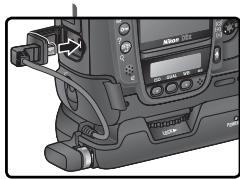
natural_image
Close-up of a camera module with attached cable and control panel (no visible text or symbols)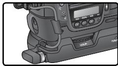
natural_image
Close-up of a professional video camera with LCD screen and buttons (no visible text or symbols)Déconnexion du WT-2
natural_image
Illustration of a woman by the sea with a sailboat and mountains in the background (no text or symbols)
natural_image
Two abstract circular icons: one with a checkered pattern inside a circle, the other with a triangular symbol inside a circle (no text or symbols)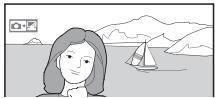
natural_image
Illustration of a woman with shoulder-length hair facing a lakeside scene with a sailboat and mountains in the background (no text or symbols)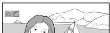
natural_image
Illustration of a person looking at mountains and waves (no text or symbols)natural_image
Illustration of a person looking at a scenic lake with mountains and a camera icon in the background (no text or symbols)natural_image
Illustration of a person looking at mountains and waves, with a camera icon in the corner (no text or symbols)Bleu : « Envoyé »
natural_image
Illustration of a person looking at mountains and waves, no text or symbols present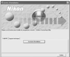
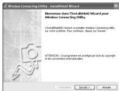
Installation (Mac OS X)
Auto IP (APIPA—Automatic Private IP Addressing)
LAN (Local Area Network)
WEP (Wired Equivalent Privacy)
Adresse IP, 8, 16, 28, 52
Adresse MAC, 31
Annotations vocales, 10
Antenne, 3
Assistant connexion, 6, 14
B
BSS-ID, 26, 51
Cartes mémoire, 9, 25, 37
Charger paramètres ?, 25
TCP/IP, 8, 16, 28, 53
No reproduction in any form of this manual, in whole or in part (except for brief quotation in critical articles or reviews), may be made without written authorization from NIKON CORPORATION.