HFSC-50LITGR - Cooker Heinner - Free user manual and instructions
Find the device manual for free HFSC-50LITGR Heinner in PDF.

| Type | Gas cooker (freestanding) |
| Brand | Heinner |
| Model | HFSC-50LITGR |
| Width | 50 cm |
| Depth | 60 cm |
| Height | 85 cm |
| Weight | Approximately 40 kg |
| Power supply | 220-240 V ~ 50/60 Hz |
| Gas type | LPG (liquid petroleum gas) / Natural gas (convertible) |
| Hob burners | 4 burners (including 1 rapid burner) |
| Oven volume | Approximately 50 L |
| Oven functions | Conventional heating with thermostat, gas grill |
| Temperature range | 50 - 250 °C |
| Timer | Mechanical timer (up to 120 minutes) with buzzer |
| Safety features | Flame failure device on hob, oven gas safety valve |
| Ignition | Automatic electric ignition (piezoelectric) |
| Cleaning | Hob: wipe with damp cloth; oven: use mild detergent and damp cloth |
| Spare parts availability | Replacement parts available through Heinner authorized service centers |
| Repair index | Repairable by qualified technicians; user-serviceable parts: none |
| Country of origin | China |
| Certifications | CE, Gas Appliance Directive |
Frequently Asked Questions - HFSC-50LITGR Heinner
User questions about HFSC-50LITGR Heinner
0 question about this device. Answer the ones you know or ask your own.
Ask a new question about this device
Download the instructions for your Cooker in PDF format for free! Find your manual HFSC-50LITGR - Heinner and take your electronic device back in hand. On this page are published all the documents necessary for the use of your device. HFSC-50LITGR by Heinner.
USER MANUAL HFSC-50LITGR Heinner
natural_image
White and black electric stove with four gas stove units (no visible text or symbols)natural_image
Diagram of a house interior with a stove, air vent, and cooling system (no text or symbols)
natural_image
Diagram of a house interior showing fire extinguishing with steam rising from the chimney (no text or symbols)natural_image
Diagram showing a window and vertical structure with an arrow indicating direction, no text or symbols present
natural_image
Simple line drawing of a room interior with a door, window, and coffee cup (no text or symbols)VII. Conectare si siguranta
CONECTAREA LA SURSA DE ALIMENTARE CU ENERGIE ELECTRICĂ
natural_image
Three-step diagram showing a lathe, hand press, and top-down view of a mechanical component (no text or symbols)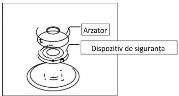
Şekil 18
natural_image
Hand holding a tool with a circular arrow indicating rotation (no text or symbols)Varugam sa acoperiti duza cu degetul, sa deschideti supapa de gaz, si verificati daca exis scurgeri folosind spuma de sapun.
natural_image
Mechanical assembly diagram showing a screwdriver inserted into a component with a tool inserted (no text or labels visible)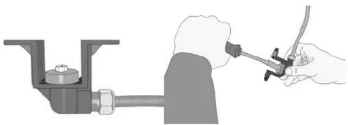
natural_image
Illustration of a hand using a tool to adjust or install a pipe fitting into a valve (no text or symbols present)natural_image
Technical illustration of a mechanical assembly with no visible text or symbolsnatural_image
Close-up of a hand using a tool to cut or mark a component, no visible text or symbols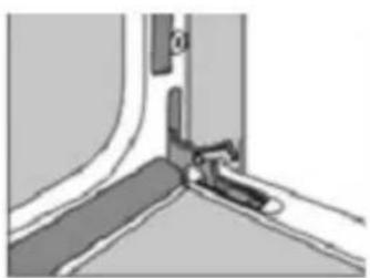
natural_image
Close-up of a mechanical joint or bracket with a handle and mounting bracket (no text or symbols visible)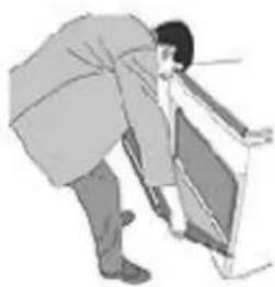
natural_image
Illustration of a person bending over a computer monitor (no text or symbols visible)natural_image
Illustration of a hand pressing down on a car door panel with a circular knob (no text or symbols)XIX. Indepartarea tavitei interioare
natural_image
Diagram of a square frame with two arrows indicating direction, no text or symbols presentnatural_image
3D rendering of a metallic X-shaped mechanical component with a central hole (no text or symbols)
INFORMATII PRIVIND DESEURI DE ECHIPAMENTE ELECTRICE SI ELECTRONICE (DEEE)
natural_image
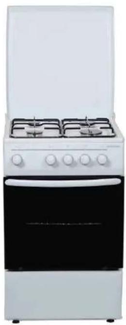
White and black electric stove with four gas stove handles open (no visible text or symbols)- Cooker
- 4 burnes
• safety device for stove and oven
• Color: White/stainless steel
Thank you for purchasing this product!
I. Introduction
Please read the instructions carefully and keep the manual for future briefings.
This manual is designed to give all necessary instructions concerning installation, use and maintenance of the unit.
To operate the unit correctly and safely, please read this instruction manual carefully before installation and use.
II. Your package
i
▶ Cooker
User Manual
Warranty card
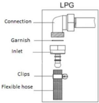
LPG conversation nozzle set
LPG hose entry
This user manual is available for the below models:
| Product code | Features |
| HFSC-50LIT | 4 burners, safety system, lamp, ignition, timer, 50 x 50 cm, white |
| HFSC-50LITG | 4 burners, safety system, lamp, ignition, timer,gGrill, 50 x 50 cm, white |
| HFSC-50LITGR | 4 burners, safety system, lamp, ignition, timer, Grill, Rotisor, 50 x 50 cm, white |
| HFSC-60LITGR | 4 burners, safety system, lamp, ignition, timer, Grill, Rotisor, 50 x 60 cm, white |
III. SAFETY PRECAUTIONS
ATTENTION
This product must be placed on flat surface.
- Using the appliance generates heat and humidity in the room. Make sure your kitchen is well ventilated.
- Intense and prolonged use of the appliance may require additional ventilation, as, for example, start and increase mechanical ventilation where there.
- When the stove is hot, do not touch its glass door freehand.
- This serves as a cooking stove. It should not be used for other purposes, for example, heating the room. All our products are exclusively for domestic use, not commercial.
- Before you start using the machine, place the curtains, paper or flammable objects away from the device. Do not store combustible or flammable objects near the appliance.
- This unit can be used by children aged 8 years or older and people with physical, sensory or mental capabilities or lack of experience and knowledge, if you were given supervision or instruction concerning use of the appliance in safe manner and that understand the risks.
Children should not be allowed to play with the appliance. Cleaning and maintenance should not be performed by children aged less than 8 years without supervision.
- Wear gloves when the stove is in operation. Do not touch hot surfaces.
- Do not lift the appliance by holding the handle.
- Do not use the stove in potentially explosive.
- If your installation security regime is less than 16 Amp, ask a qualified electrician to mind a 16 Amp fuse.
- When using the oven, some parts may become hot. Children must be supervised and keep a distance and watching constant.
- Do not splash tray inside the oven or cold water when the surface of the appliance is still hot. Steam rises can cause burns, and the sudden change in temperature can damage the surface of the device.
Warning: All our appliances are only for domestic use, not for commercial use.
THIS APPLIANCE SHALL BE INSTALLED IN ACCORDANCE WITH THE REGULATIONS IN FORCE AND ONLY USED IN A WELL VENTILATED SPACE. READ THE INSTRUCTIC BEFORE INSTALLING OR USING THIS APPLIANCE
• WARNING: This appliance must be earthed!
- Please find required information as power and ratings for your cooker from rating label is which located behind of appliance.
• Ensure that the electricity supply is turned OFF before installing your appliance.
- Ensure that the appliance is switched off before replacing the lamp to avoid the possibility of electric shock.
- If the supply cord is damaged, it must be replaced by the manufacturer, its services agent or similar qualified persons in order to avoid hazard.
- Keep the electrical cable of your cooker away from the hot areas; do not let them touch the appliance. Keep them away from sharp sides and heated surfaces.
• Usage of your appliance creates moisture and heat in the room; make sure that your kitchen is well ventilated.
- Prolonged intensive use of the appliance may call for additional ventilation, for example opening increasing the level of mechanical ventilation where present.
- When the cooker is hot never touch the cooker glass by hand.
- This appliance is for cooking purposes only. It must not be used for other purposes, for example room heating. All our appliances are only for domestic use, not for commercial use.
- Before starting to use your appliance, keep curtains, paper or inflammable things away from your appliance. Do not keep combustible or inflammable things in or near the appliance.
- This appliance can be used by children aged from 8 years and above and persons with reduced physical, sensory or mental capabilities or lack of experience and knowledge if they have been given supervision or instruction concerning use of the appliance in a safe way and understand the hazards involved. Children shall not play with the appliance. Cleaning and user maintenance shall not be made by children unless they are older than 8 and supervised.
• Use glove when using cooker. Do not touch on hot surfaces.
- Do not carry cooker to hold from handle
- Do not use cooker in potentially explosive atmospheres.
- If the current rate of the fuse in your installation is less than 6 Amp, have a qualified electrician fit a6 Amp fuse.
- When the oven is being used, some parts may become hot; children should be kept away and supervised at all times.
- Do not splash cool water in an oven tray or inside the oven when the surface of the appliance is still hot. Arising steam may cause burns and sudden temperature exchange may cause damages on the surface of the appliance
- WARNING: Accessible parts may become hot during use. Young children should be kept away.
- WARNING: The appliance and its accessible parts become hot during use. Care should be taken to avoid touching heating elements. Children less than 8 years of age shall be kept away unless continuously supervised.
- Do not use harsh abrasive cleaners or sharp metal scrapers to clean the oven door glass since they can scratch the surface which may result in shattering of the glass.
- If the current rate of the fuse in your installation is less than 6 Ampere, have a qualified electrician fit a 6 A. fuse.
- This appliance is produced in accordance with the safety regulations. Incorrect use will harm people and appliance.
- The cooker must be supplied via a suitable double pole isolating switch, having contact separation of at least 3 mm in all poles placed in a readily accessible position adjacent to the unit.
- Children should be supervised to ensure that they do not play with the appliance. Never let them play with the appliance.
- The cooker may be located in a kitchen, a kitchen/diner or bed-sitting room but not in a room containing a bath or shower.
- Caution: glass lids may shatter when heated. Turn off all the burners before shutting the lid. Any spillage should be removed from the lid before opening.
- In models that have digital timer, after power cut set your digital timer rightly. Otherwise, your oven will not operate.
- Caution: Accessible parts may be hot when the grill is in use. Young children should be kept away"
- Do not put flammable, combustible, explosive liquid able or deformable by heat any material in the oven against possible risk of danger even if your appliance is not in use.
- Bread may catch fire if the toasting time is too long. Close supervision is necessary during toasting
- For cleaning fan guard panel (optional) the cooker must be switched off before removing the guard and after cleaning, the guard must be replaced in correct position into the cooker.
- WARNING: Before obtaining access to terminals, all supply circuits must be disconnected.
- WARNING: Unattended cooking on a hob with fat or oil can be dangerous and may result in fire. NEVER try to extinguish a fire with water, but switch off the appliance and then cover flame e.g. with a lid or a fire blanket.
• WARNING: Danger of fire: do not store items on the cooking surfaces.
- WARNING: If the surface is cracked, switch off the appliance to avoid the possibility of electric shock.
IV. Technical details
| SPECIFICATIONS | 50 x 50 | 50 x 60 | 60 x 60 |
| External width | 500 mm | 500 mm | 600 |
| Exterior Depth | 600 mm | 660 mm | 660 |
| Exterior Height | 850 mm | 850 mm | 850 |
| Interior width | 395 mm | 395 mm | 445 |
| Internal depth | 405 mm | 405 mm | 445 |
| Internal height | 330 mm | 330 mm | 330 |
| Power lamp * | 15-25 W | ||
| Thermostat | 50 - 250 °C | ||
| The heating of the bottom | 800 W | 800 W | 1300 W |
| The heating of the upper | 650 W | 650 W | 850 W |
| The heating element of the grill * | 1500 W | 1500 W | 2000 W |
| Power supply * | 220-240V AC, or 230V AC, 50 - 60 Hz. | ||
* = optional depending on model
| BURNER INJECTOR VALUES ACCORDING TO THE GAS TYPE | LPG | Natural gas | Natural gas | Natural gas | ||
| G30-30 mbar | G20-20 mbar | G20-25 mbar | G25-25 mbar | |||
| Wok Burner* | Injector | mm | 0.90 | 1.20 | 1.20 | 1.20 |
| Power | KW | 3.00 | 2.70 | 2.79 | 2.70 | |
| Consumption | gr/h, m3/h | 236 | 0.275 | 0.290 | 0.311 | |
| Rapid Burner | Injector | mm | 0.80 | 1.15 | 1.05 | 1.20 |
| Power | KW | 2.50 | 2.50 | 2.50 | 2.70 | |
| Consumption | gr/h, m3/h | 197 | 0.234 | 0.237 | 0.310 | |
| Semi-rapid Burner | Injector | mm | 0.65 | 0.97 | 0.92 | 0.94 |
| Power | KW | 1.70 | 1.70 | 1.70 | 1.70 | |
| Consumption | gr/h, m3/h | 133 | 0.168 | 0.160 | 0.195 | |
| Auxiliary Burner | Injector | mm | 0.50 | 0.72 | 0.70 | 0.72 |
| Power | KW | 0.90 | 0.90 | 0.95 | 0.90 | |
| Consumption | gr/h, m3/h | 70 | 0.085 | 0.094 | 0.105 | |
| Oven Burner | Injector | mm | 0.75 | 1.10 | 1.00 | 1.10 |
| Power | KW | 2.20 | 2.20 | 2.30 | 2.30 | |
| Consumption | gr/h, m3/h | 173 0.218 | 0.220/0.219 | 0.256/0.254 | ||
| Grill Burner | Injector | mm | 0.60 | 0.92 | 0.85 | 0.94 |
| Power | KW | 1.45 | 1.45 | 1.40 | 1.75 | |
| Consumption | gr/h, m3/h | 114 0.144 | 0.132/0.131 | 0.185/0.186 | ||
* = optional depending on model
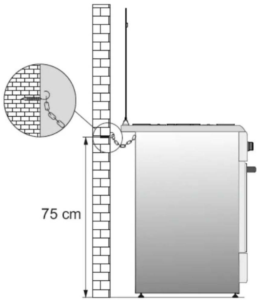
V. Fixing in the wall
FIXING IN THE WALL (\*) Optional
To use the stove safely, make sure first that it fixed on the wall using the chain and hook screw provided. Make sure the hook that was screwed into the wall.
WARNING
To prevent tilt device, you must install these means of stabilization. See the instructions for installation.
VI. Gas network connection
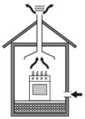
WARNING! This appliances must be installed only in a room ventilated permanent, confirm with regulations.
This unit is not connected to a combustion products evacuation. Will be installed and connected in accordance with regulations in terms of installation. Increased attention will be given to ventilation requirements applicable areas.
natural_image
Diagram of a greenhouse with a stove inside, showing airflow and ventilation (no text or symbols)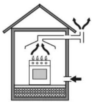
natural_image
Diagram of a house interior showing fire extinguishing from a stove, with airflow arrows indicating heat distribution (no text or labels)The use of a gas cooking appliance generates heat and humidity in the room where it is installed. Make sure the kitchen is well ventilated: keep natural ventilation holes free or install a mechanical ventilation (fume extraction).
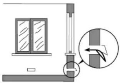
Intense and prolonged use of the appliance may require additional ventilation, such as opening a window, or more effective means of ventilation, and mechanical ventilation increased intensity where there.
natural_image
Diagram showing a window and vertical structure with an arrow indicating direction, no text or symbols present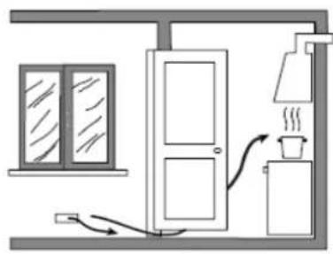
natural_image
Simple line drawing of a room interior with a window, door, and coffee cup (no text or symbols)VII. Connection and safety
ELECTRICAL CONNECTION
• The adjustment conditions for this appliance are stated on the rating label.
- Your appliance requires 6 Ampere supply according to total power of your cooker. Please find all required values from rating label of your cooker. If necessary, installation by a qualified electrician is recommended.
- Electrical connection of the cooker-+ should only be made to connections/sockets with an earth system installed in compliance with local regulations. If there are no connections/sockets with an earth system in place where the cooker will be installed, immediately contact a qualified electrician to install. The manufacturer is not responsible for damages that will arise because of the appliance not be connected to an earth system.
- Your cooker is for use with 220-240V AC or 230VAC for mono phase electric supply. If your supply is different from the specified value, contact your authorized service agent.
- When placing your cooker to its location, ensure that it is at the counter level. Bring it to the counter level by adjusting the feet if necessary.
- Before installation, ensure that the local distribution conditions (nature and pressure of gas) and settings adjustment device are compatible.
- Conditions of adjustment for this unit are mention the energy label (or on the rating plate identification).
- This unit is not connected to a combustion products evacuation. Will be installed and connected in accordance with regulations in terms of installation. Attention will be paid to the applicable requirements venting incidents.
- Fit the hose clamp. Push one end of the pipe until it touches the hose.
- To check the seal: make sure the command buttons on the control panel are closed, but the gas cylinder is opened. Apply some soap bubbles in the connection. If gas leaks occur, the foam will form in the area.
- The cooker must be in a well-ventilated room, on a flat surface.
- Check the gas.
- When you place the stove in place, make sure it is leveled. If needed, adjust the feet.
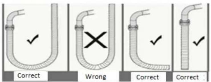
- Do not leave gas hose near hot areas, especially in the back of the oven. Do not move the appliance connected to the gas, because the force that can weaken the hose, causing gas leaks.
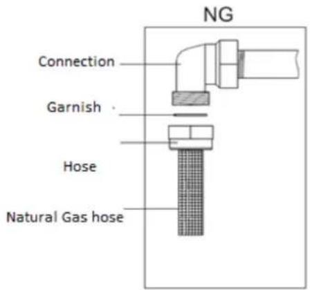
- Please use flexible hoses to connect to the gas.
- Sign in LPG cooker quickly and without risk of leakage. Min. 40 cm Max. 125 cm.
- When you do check for gas leaks, never use lighters, matches, cigarettes or other.
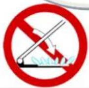
Attention: Do not close the lid when the burners are on.
Connection diagram for LPG
Connection diagram for Natural Gas
VIII. Cooker description
Symbols function cooker:

Closed

Small flame

Big Flame

Ignition

Manual Using

Timer

Oven burner

Oven lamp

Grill burner

Grill & turnspit

Turnspit
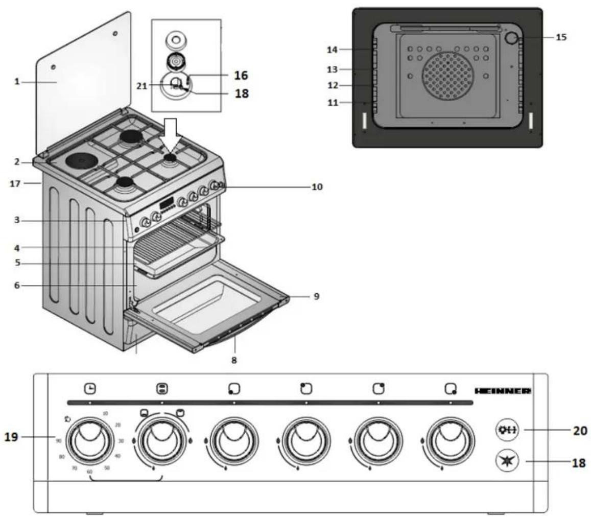
- Top cover
- Cooktop
- Control panel
- Ware grid
- Tray
- Cavity
- Buttom cover
- Door handle
- Wall fixing chain
- Timer
-
Nozzles
-
Oven door
-
Knobs control
- Buttom shelve
- Middle down shelve
-
Top shelfve
-
Higher level
- Oven lamp (Optional)
- Safety Device for Burner
- Ignition
- Rotisserie&Lamp(Optional)
IX. Using the cooker
CAUTION: THIS APPLIANCE MUST ONLY BE INSTALLED IN A PERMANENTLY VENTILATED ROOM IN COMPLIANCE WITH THE APPLICABLE REGULATIONS.
This appliance is not connected to a combustion products evacuation device. It shall be installed and connected in accordance with current installation regulations. Particular attention shall be given to the relevant requirements regarding ventilation.
Attention: Before using the appliance please remove it from all bands flammable polystyrene packaging or other packaging. Also, remove the user manual and any other flammable materials inside the cooker.
The use of a gas cooking appliance results in production of heat and moisture in the room in which it is installed. Ensure that the kitchen is well ventilated: keep naturel ventilation holes open or install a mechanical ventilat, ion device (mechanical extractor hood).
Prolonged intervise use of the appliance may call for additional ventilation, for example opening of a window, or more effective ventilation, for example increasing the level of mechanical ventilation where present.
The use of gas burners:
Burner operated by each knob in hand marked with signs on the side of each button on the control panel.
Press and turn the knob corresponding to the opposite clockwise until the symbol (+). To turn off the burner, turn the corresponding knob clockwise until it stops. Button are different symbols for off, for maximum flame intensity and minimum intensity of the flame.
-
Your oven is equipped with burners on gas, use the knob to turn the burners properly.
-
Safety device when the flame is extinguished cooker control valve immediately cease gas supply. To operate the burners of this type, you have to press the button and turn it counterclockwise. After ignition, you should wait about 5-10 seconds to activate the gas safety system. If the burner goes out for any reason, close the gas control valve and wait at least one minute before trying again.
Using oven heating elements:
- At first using the oven, it will give off an odor that comes from the heating elements. To get rid of it, put it to idle for 45-60 minutes at a temperature of 250 °C.
- Oven control knob must be set to the desired value, otherwise it will not work.
- Cooking time: Results may vary depending on the voltage and materials with different qualities, in various amounts and at various temperatures.
- During the cooking in the oven, its door should not be opened frequently. Otherwise, hot air circulation may be unbalanced and results may vary.
- Use cake baking forms give better results. We've got heat for 5-10 minutes before starting to cook.
Before using the stove, make sure the burner caps are properly positioned. Their correct positioning is illustrated below:
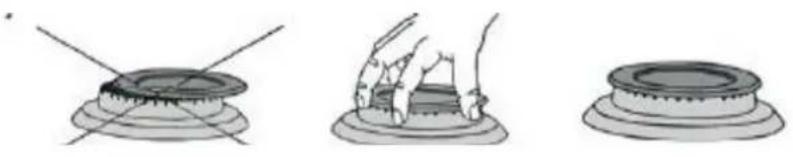
natural_image
Three-step illustration showing a hand pressing down on a circular object, with no text or symbols present.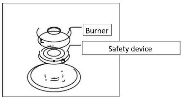
| THE BURNER STAIN DIAMENTER PAN | |
| Pan wok burner 24 - 28 cm | |
| Fast burner 22 - 26 cm | |
| Semi-fast burner | 18 - 22 cm |
| Auxiliary burner | 12 - 18 cm |
Smart Burner Cell (Optional)
1- Cooking time is adjusted by turning the control knob to the right (Example: 30 mins.) as below:
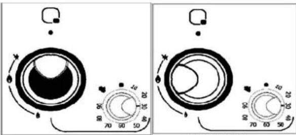
Şekil 18
2- After the time is adjusted, press the burner control knob and turn it to the left (counterclockwise) to the flame symbol and ignite burner. After the burning commences, make the safety system go on by keeping the knob pressed down for 5-10 seconds.
3- If the burning does not take place after you press and release the knob, repeat the 2nd step.
4- After the duration that was set in the timer, the flame on the burner will be automatically cut off and a notification "bing" sound will be heard. End the process by turning the control knob of the smart burner to ( ) position.
WARNING: Time setting is not possible when the knob on position with hand mark C. Burner runs forever.
Using gas oven:
Which burner will be used with which corresponding knob is defined by signs on the knob frame or on command panel.
Control for oven burner: Push forward and turn the corresponding knob in counter clockwise direction to the max. (+) symbol. To turn off the burner turn the corresponding knobs clockwise until it stop
Shown on the knob are different symbols for off as ●, for maximum flame as ◆ and minimum flame as ◆.
Control for grill burner: Push forward and turn the corresponding knob in clockwise direction to the max.
(+) symbol.
Notes:
* When you start to operate oven burners please do not close oven door and wait 3 minutes as open position.
* If your cooker has two separate control knob to operate oven and grill burner please push forward and turn the corresponding knob in counter clockwise direction to the max.
* If your cooker has thermostat, mentioned control knob should be positioned to desired temperature value. (Optional)
*If your cooker has smart gas oven option (timer with cut off function), please follow up recommendations as mentioned on smart burner cell.
* If your cooker has mechanical timer, timer knob should be positioned to desired timing value. End of adjusted cooking time, will heard "bing" tone from timer. The timer is only for warning about time. It can not operate the cooker.
Cooking Time Table:
| Meals | Temperature (°C) | Rack position | Cooking time (min.) |
| Creamed cake | 150 - 170 | 2 | 30 - 35 |
| Pastry | 200 - 220 | 2 | 35 - 45 |
| Biscuit | 160 - 170 | 3 | 20 - 25 |
| Cookie | 160 – 170 | 3 | 20 - 35 |
| Cake | 160 - 180 | 2 | 25 - 35 |
| Braided cookie | 200 - 220 | 2 | 30 - 40 |
| Filo pastry | 180 - 220 | 2 | 35 - 45 |
| Savory pastry | 160 - 180 | 2 | 20 - 30 |
| Lamb meat | 200 - 230 | 1 | 90 - 120 |
| Veal | 200 - 230 | 1 | 90 - 120 |
| Mutton | 210 - 230 | 1 | 90 - 120 |
| Chicken (in | 210 - 230 | 1 | 75 – 100 |
| Fish | 190 - 210 | 2 | 40 – 50 |
Note: The results may change according to the area voltage and material having different quality, amount and temperatures. Using cake forms while cooking cake gives better result.
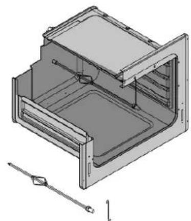
USING TURNSPIT (\*) Optional
If your cooker has turnspit option please follows recommendations as below; Install turnspit hook to the fixing hole on the cavity. Put the cooking item (chicken etc.) on grill swollen and fix by sword and screws. Than install them on turnspit motor as shown in below figures and operate turnspit system from command knob from control panel.
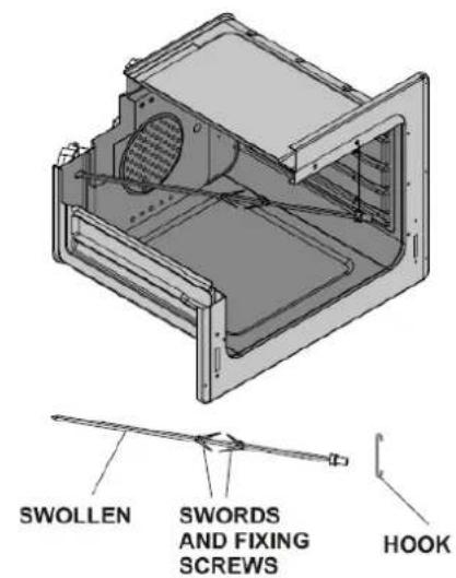
natural_image
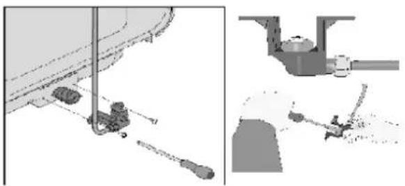
Technical line drawing of a mechanical housing or enclosure with internal components and a tool, no text or symbols present.X. Change nozzels
-
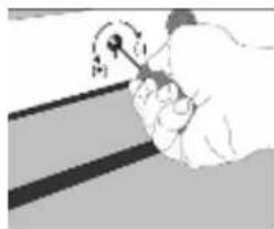
First, disconnect the gas supply to the cooker. Please use a special screwdriver to remove the nozzle and install new ones.
-
Please use a special screwdriver nozzle removal and installation of new ones.
natural_image
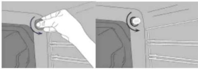
Hand holding a tool with a circular arrow and pointer, pointing at a surface (no text or symbols visible)- Please cover the nozzle with your finger to open the gas valve and check for leaks using soap bubbles.
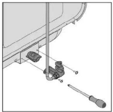
Nozzle change operation for oven burners:
Please remove back cover of cooker and remove nozzle fixing body from burner. Then remove nozzle from injector body with special nozzle driver for change nozzle. After change close nozzle hole by finger, open gas valve and check gas leakage by soap foam from round of nozzle-body connection surface. Then re-install nozzle body to the burner by screws.
natural_image
Mechanical assembly diagram showing a tool inserted into a component with a screwdriver inserted (no text or labels)
natural_image
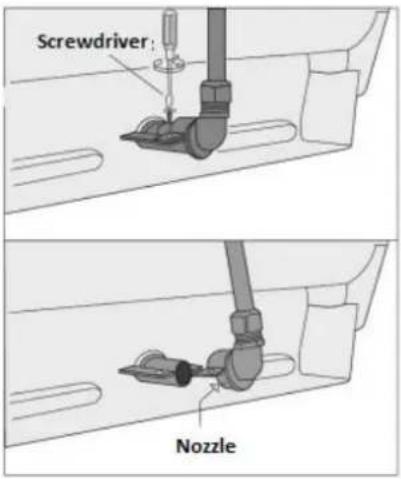
Illustration of a hand using a tool to adjust or install a pipe fitting into a valve (no text or symbols present)XI. Burners oven
Please remove the cover from the top of the stove and fixtures remove nozzle stove. Then remove the injector nozzle body with a screwdriver specially designed.
After a change, cover the nozzle orifice finger, open the gas valve and check for leaks using soap bubbles in the record. Then reinstall the stove nozzle screws.
For other types of burners:
natural_image
Technical illustration of mechanical assembly with tool and component views (no text or symbols)XII. Intensity adjustment flame gas valve
To adjust the oven according to the type of gas, carefully perform the adjustment for low intensity flame, turning with a screwdriver small, as indicated below, the screw in the center of the gas valve and replace the nozzle.
| From LPG to natural gas From natural gas to LPG | ||
| Fast burner | 3 turning it counterclockwise | 3 turning in clockwise |
| Semi-fast burner | 2,5 turning it counterclockwise | 2,5 turning in clockwise |
| Auxilliary burner | 2 turning it counterclockwise | 2 turning in clockwise |
| Burner pan wok | 4 turning it counterclockwise | 4 turning in clockwise |
| Oven burner | 4,5 turning it counterclockwise | 4,5 turning in clockwise |
| Grill burner | 4turning it counterclockwise | 4 turning in clockwise |
XIII. If the burner is not functioning
- Please check the main gas valve.
• Gas hose can be broken or bent. - Please check connection oven gas hose.
- Please check the gas flow noise.
- Please check whether the gas valve is suitable for your oven.
- If you can not resolve the problem, contact the support of producer/supplier, service agent or qualified service personnel.
XIV. Using the heat display
Safety plate is designed to protect the control panel and buttons when the furnace operates in mode "Barbecue". Place the plate in the control panel opening safety glass front door of the oven.
Then fix between microwave safe plate and the front door, closing it gently on the latter.
Please use this safety plate to avoid damage to the control panel and buttons because of heat when the furnace operates in mode "Barbecue".
It is important when cooking on the grill, to keep the door open at the specified distance. Safety plate provide ideal conditions for cooking, preserving at the same time, control panel and buttons.
XV. IF THE APPLIANCE DOES NOT OPERATE
| Problem | Possible Causes | Suggested Solutions |
| Oven is not working | Fuse malfunction or automatic fuse blown | Check the general fuse box and correct if there are any thrown breakers. Check the general fuse box to see if the automatic fuse or the breakers are thrown off. If the problem repeats, call technical service to remove the reason of the fuse blowing. |
| The device is unplugged to (grounded) power socket | Make sure the unit is plugged in | |
| Oven light is not working | Oven lamp is defective. | Change the lamp. |
| There is no any current | Check the general fuse box and correct if there are any thrown breakers. Check the general fuse box to see if the automatic fuse or the breakers are thrown off. If the problem repeats, call technical service to remove the reason of the fuse blowing. | |
| Oven is not heating | Oven temperature and/or cooking mode has not been selected | Set the cooking mode and temperature |
| There is no any current | Check the general fuse box and correct if there are any thrown breakers. Check the general fuse box to see if the automatic fuse or the breakers are thrown off. If the problem repeats, call technical service to remove the reason of the fuse blowing. |
Gas equipments
| Does not spark ignition. | There is no any current | Check the general fuse box and correct if there are any thrown breakers. |
| Main gas valve is turned off | Turn on the main gas valve | |
| Gas hose is bent. | Connect the gas hose out properly. | |
| Gas does not come | Burner injectors are clogged. Clean the injectors | |
| Gas hose is bent. | Connect the gas hose out properly. | |
| Uneven flame / No flame | Burner injectors are clogged. | Clean the injectors |
| Burners might be wet. | Dry the burner parts carefully. | |
| Burner caps might not be placed correctly. | Make sure the caps and the burners are placed correctly. | |
| Main gas valve is turned off | Turn on the main gas valve | |
| Empty gas bottle (LPG is used) Replace with new bottle | ||
Digital Timer/ Display (models with digital timer)
| Problem | Possible Causes | Suggested Solutions |
| Time display is flashing or lit up clock. | Before power failure occurs. | Set the current time. Turn off the cooking mode and re-rotate the cooking mode you desired |
If the problem is not solved:
3) Cut the electricity connection of unit (turn off the circuit breaker)
4) Call the manufacturer, its services agent or similar qualified persons
IMPORTANT
Do not try to repair the device yourself. There are no any parts inside the product may be repaired by customer.
XVI. Cleaning and maintenance
- When the oven is in operation or soon after beginning operation, it is extremely hot. You need to avoid touching heating elements.
- Never clean the inside panel cover, trays and any other parts of the oven and brush tools harsh scouring pads or knives. Do not use abrasive cleaning agents and detergents and aggressive.
- After cleaning the internal parts of the oven with a cloth soaked with soap, rinse it, then dry it thoroughly with a soft cloth.
- Clean glass surfaces with specially formulated cleaning agents.
- Do not clean the oven with a cleaning device on steam.
- Before opening the top cover of the stove, clean spilled liquids on it. Also, before you get out, make sure that cooking surface has cooled well enough.
- Never use flammable agents such as acid, paint thinner or benzine to clean the oven.
- Do not wash any of the parts of the oven dishwasher.
XVII. Removing the oven door
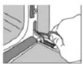
natural_image
Illustration of a hand using a tool to adjust or install a component, no text or symbols visible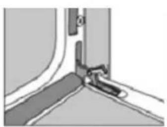
natural_image
Close-up of a mechanical joint or bracket detail with no visible text or symbols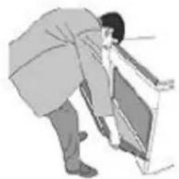
natural_image
Illustration of a person bending over a chair (no text or symbols visible)XVIII. Changing oven lamp
Let the oven cavity and grill burner or heating elements cool down. Cut off the electrical connection of your appliance before chancing the inner lamp. Change with a 15-25W, 300 C° temperature resistant lamp.
natural_image
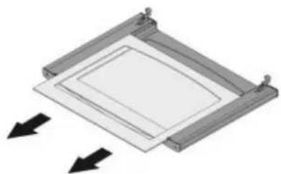
Illustration of a hand pressing a button on a vehicle door panel (no text or symbols visible)XIX. Removing interior tray
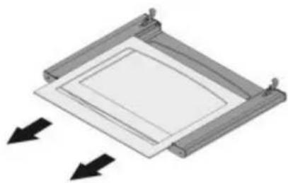
natural_image
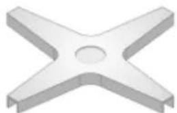
Diagram of a square frame with two arrows indicating direction, no text or symbols presentXX. Using the pot support
Pot holder's wear is useful to use of the burners pots with small diameter. Place holder in the middle, then put the kettle to use it.
natural_image
3D rendering of a metallic X-shaped mechanical component with a central hole (no text or symbols)
Environment friendly disposal
You can help protect the environment!
Please remember to respect the local regulations: hand in the non-working electrical equipment's to an appropriate waste disposal center.

HEINNER is a registered trademark of Network One Distribution SRL. Other brands and product names are trademarks or registered trademarks of their respective holders.
No part of the specifications may be reproduced in any form or by any means or used to make any derivative such as translation, transformation, or adaptation without permission from NETWORK ONE DISTRIBUTION.
Copyright © 2013 Network One Distribution. All rights reserved.
www.heinner.com, http://www.nod.ro
http://www.heinner.com, http://www.nod.ro

This product is in conformity with norms and standards of European Community
Importer: Network One Distribution
Marcel Iancu Street, 3-5, Bucharest, Romania
Tel: +40 21 211 18 56, www.heinner.ro, www.nod.ro
HEINNER
ПЕЧКА
Модел: HFSC-50SW
HFSC-50LIT
HFSC-50LITG
HFSC-50LITGR
HFSC-60LITGR
natural_image
White electric stove with four gas stove handles and open top (no visible text or symbols)natural_image
Diagram of a house interior with a stove and airflow arrows, no text or symbols present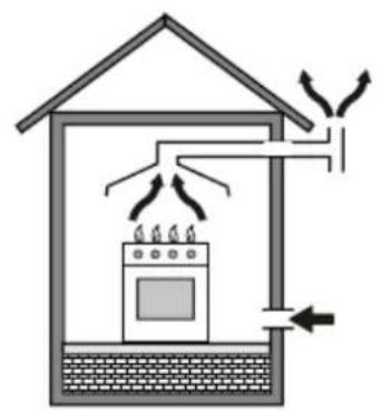
natural_image
Diagram of a house interior with a stove, air ducts, and cooling system (no text or symbols)natural_image
Diagram showing a window and vertical structure with an arrow indicating direction, no text or symbols present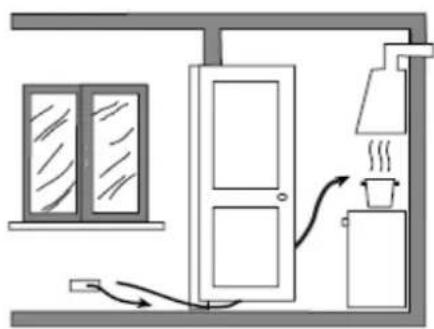
natural_image
Simple line drawing of a room interior with a door, cabinet, and heating unit (no text or symbols)natural_image
Three-step diagram showing a lathe, hand press, and top-down view of a mechanical component (no text or symbols)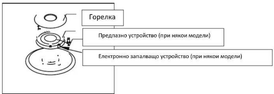
Şekil 18
natural_image
Technical line drawing of a mechanical housing or enclosure with internal components and a tool, no text or symbols present.X. Смяна на дюзите
natural_image
Illustration of a hand holding a tool with a circular arrow and pointer (no text or symbols)natural_image
Mechanical assembly diagram showing a tool inserted into a component with labeled parts (no text or symbols present)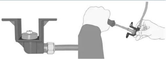
natural_image
Illustration of a hand using a tool to adjust or install a pipe fitting into a valve (no text or symbols present)XI. ЗА ГОРЕЛКИТЕ НА ФУРНАТА
natural_image
Technical diagram of a mechanical assembly with no visible text or symbols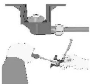
natural_image
Diagram of a mechanical assembly with a pipe and tool, no visible text or symbolsnatural_image
Illustration of a hand using a tool to cut or mark a piece of material, no text or symbols visible
natural_image
Pure mechanical assembly diagram without any text, numbers, or symbols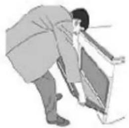
natural_image
Illustration of a person bending over a chair (no text or symbols visible)natural_image
Illustration of a hand pressing down on a mechanical component with a circular knob (no text or symbols)natural_image
Diagram of a square frame with arrows indicating direction, no text or symbols presentnatural_image
3D rendering of a metallic X-shaped mechanical component with a central hole (no text or symbols)
ИЗХВЪРЛЯНЕТО НА ОТПАДЪЦИТЕ ПО ОТГОВОРЕН НАЧИН КЪМ ОКОЛНАТА СРЕДА
Copyright © 2013 Network One Distribution. All rights reserved.
www.heinner.com, http://www.nod.ro
http://www.heinner.com, http://www.nod.ro

natural_image
White gas stove with four stoves and open lid, no visible text or symbolsnatural_image
Diagram of a house interior with a stove, air vent, and cooling system (no text or labels)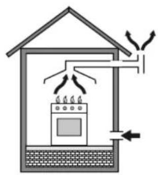
natural_image
Diagram of a house interior showing airflow from a stove to a roof, with no text or symbols present.natural_image
Diagram showing a window and vertical structure with an arrow indicating direction (no text or symbols)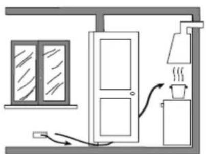
natural_image
Simple line drawing of a room with a door, window, and heating unit (no text or symbols)natural_image
Three-step diagram showing a mechanical assembly: top view, hand pressing on a circular component, and bottom view (no text or symbols)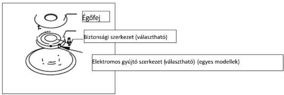
Şekil 18
natural_image
Technical line drawing of a mechanical housing assembly with internal components and a tool (no text or symbols)natural_image
Hand holding a tool with a circular arrow indicating rotation (no text or symbols)natural_image
Mechanical assembly diagram showing a screwdriver inserted into a pipe and two parts mounted on a base (no text or symbols visible)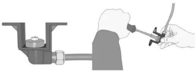
natural_image
Illustration of a hand using a tool to adjust or install a pipe fitting into a valve (no text or symbols present)XI. A SÜTŐ ÉGŐKNÉL
natural_image
Technical illustration of a mechanical assembly with tool and component details (no text or symbols)natural_image
Close-up of a hand using a sewing machine to trim or cut a garment (no text or symbols visible)
natural_image
Pure mechanical assembly diagram showing a bracket and mounting bracket without any text or symbols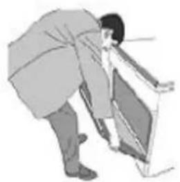
natural_image
Illustration of a person bending over a door (no text or symbols visible)XVIII. Izzócsere
natural_image
Illustration of a hand pressing a button on a vehicle door panel (no text or symbols visible)natural_image
Diagram of a square frame with arrows indicating direction, no text or symbols presentnatural_image
3D rendering of a metallic X-shaped mechanical part with a central hole (no text or symbols)
KÖRNYEZETTUDATOS HULLADÉKKEZELÉS
Copyright © 2013 Network One Distribution. All rights reserved.
http://www.heinner.com, http://www.nod.ro