USER MANUAL WR450F-2007 YAMAHA
OWNER'S SERVICE MANUAL
MANUEL D'ATELIER DU
PROPRIETAIRE
FAHRER- UND
WARTUNGS-HANDBUCH
MANUAL DE SERVICIO
DEL PROPIETARIO
WR450F(W)
5TJ-28199-44
EC010010
WR450F(W)
OWNER'S SERVICE MANUAL
©2006 by Yamaha Motor Co., Ltd.
1st Edition, August 2006
All rights reserved.
Any reprinting or unauthorized use
without the written permission of
Yamaha Motor Co., Ltd.
is expressly prohibited.
Printed in Japan
WR450F(W)
MANUEL D'ATELIER
DU PROPRIETAIRE
©2006 Yamaha Motor Co., Ltd.
Congratulations on your purchase of a Yamaha WR series. This model is the culmination of Yamaha's vast experience in the production of pacesetting racing machines. It represents the highest grade of craftsmanship and reliability that have made Yamaha a leader.
This manual explains operation, inspection, basic maintenance and tuning of your machine. If you have any questions about this manual or your machine, please contact your Yamaha dealer.
NOTE:
Yamaha continually seeks advancements in product design and quality. Therefore, while this manual contains the most current product information available at the time of printing, there may be minor discrepancies between your machine and this manual. If you have any questions concerning this manual, please consult your Yamaha dealer.
WARNING
PLEASE READ THIS MANUAL CAREFULLY AND COMPLETELY BEFORE OPERATING THIS MACHINE. DO NOT ATTEMPT TO OPERATE THIS MACHINE UNTIL YOU HAVE ATTAINED A SATISFACTORY KNOWLEDGE OF ITS CONTROLS AND OPERATING FEATURES AND UNTIL YOU HAVE BEEN TRAINED IN SAFE AND PROPER RIDING TECHNIQUES. REGULAR INSPECTIONS AND CAREFUL MAINTENANCE, ALONG WITH GOOD RIDING SKILLS, WILL ENSURE THAT YOU SAFETY ENJOY THE CAPABILITIES AND THE RELIABILITY OF THIS MACHINE.
INTRODUCTION
THIS MACHINE IS DESIGNED STRICTLY FOR COMPETITION USE, ONLY ON A CLOSED COURSE. It is illegal for this machine to be operated on any public street, road, or highway. Off-road use on public lands may also be illegal. Please check local regulations before riding.
- THIS MACHINE IS TO BE OPERATED BY AN EXPERIENCED RIDER ONLY.
Do not attempt to operate this machine at maximum power until you are totally familiar with its characteristics.
- THIS MACHINE IS DESIGNED TO BE RIDDEN BY THE OPERATOR ONLY.
Do not carry passengers on this machine.
- ALWAYS WEAR PROTECTIVE APPAREL.
When operating this machine, always wear an approved helmet with goggles or a face shield. Also wear heavy boots, gloves, and protective clothing. Always wear proper fitting clothing that will not be caught in any of the moving parts or controls of the machine.
- ALWAYS MAINTAIN YOUR MACHINE IN PROPER WORKING ORDER.
For safety and reliability, the machine must be properly maintained. Always perform the pre-operation checks indicated in this manual. Correcting a mechanical problem before you ride may prevent an accident.
NOTICE IMPORTANTE
- GASOLINE IS HIGHLY FLAMMABLE.
Always turn off the engine while refueling. Take care to not spill any gasoline on the engine or exhaust system. Never refuel in the vicinity of an open flame, or while smoking.
- GASOLINE CAN CAUSE INJURY.
If you should swallow some gasoline, inhale excess gasoline vapors, or allow any gasoline to get into your eyes, contact a doctor immediately. If any gasoline spills onto your skin or clothing, immediately wash skin areas with soap and water, and change your clothes.
- ONLY OPERATE THE MACHINE IN AN AREA WITH ADEQUATE VENTILA-TION.
Never start the engine or let it run for any length of time in an enclosed area. Exhaust fumes are poisonous. These fumes contain carbon monoxide, which by itself is odorless and colorless. Carbon monoxide is a dangerous gas which can cause unconsciousness or can be lethal.
- PARK THE MACHINE CAREFULLY; TURN OFF THE ENGINE.
Always turn off the engine if you are going to leave the machine. Do not park the machine on a slope or soft ground as it may fall over.
- THE ENGINE, EXHAUST PIPE, MUFFLER, AND OIL TANK WILL BE VERY HOT AFTER THE ENGINE HAS BEEN RUN.
Be careful not to touch them or to allow any clothing item to contact them during inspection or repair.
-
PROPERLY SECURE THE MACHINE BEFORE TRANSPORTING IT.
When transporting the machine in another vehicle, always be sure it is properly secured and in an upright position and that the fuel cock is in the “OFF” position. Otherwise, fuel may leak out of the carburetor or fuel tank.
-
L'ESSENCE EST HAUTE-MENT INFLAMMABLE.
This manual will provide you with a good basic understanding of features, operation, and basic maintenance and inspection items of this machine. Please read this manual carefully and completely before operating your new machine. If you have any questions regarding the operation or maintenance of your machine, please consult your Yamaha dealer.
NOTE:
This manual should be considered a permanent part of this machine and should remain with it even if the machine is subsequently sold.
EC060000
NOTICE
Some data in this manual may become outdated due to improvements made to this model in the future. If there is any question you have regarding this manual or your machine, please consult your Yamaha dealer.
EC070001
F.I.M. MACHINE WEIGHTS:
Weights of machines without fuel
The minimum weights for motocross machines are:
for the class 125 cc ...... minimum
88 kg (194 lb)
for the class 250 cc ...... minimum
98 kg (216 lb)
for the class 500 cc ...... minimum
102 kg (225 lb)
In modifying your machine (e.g., for weight reduction), take note of the above limits of weight.
AU NOUVEAU PROPRIETAIRE
The Safety Alert Symbol means ATTENTION!
BECOME ALERT! YOUR SAFETY IS
INVOLVED!

WARNING
Failure to follow WARNING instructions could result in severe injury or death to the machine operator, a bystander, or a person inspecting or repairing the machine.
CAUTION:
A CAUTION indicates special precautions that must be taken to avoid damage to the machine.
NOTE:
A NOTE provides key information to make procedures easier or clearer.
EC082000
FINDING THE REQUIRED PAGE
-
This manual consists of seven chapters; "General Information", "Specifications", "Regular inspection and adjustments", "Engine", "Chassis", "Electrical" and "Tuning".
-
The table of contents is at the beginning of the manual. Look over the general layout of the book before finding then required chapter and item.
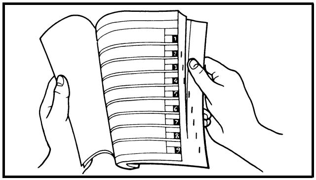
Bend the book at its edge, as shown, to find the required fore edge symbol mark and go to a page for required item and description.

All of the procedures in this manual are organized in a sequential, step-by-step format. The information has been complied to provide the mechanic with an easy to read, handy reference that contains comprehensive explanations of all disassembly, repair, assembly, and inspection operations.
In this revised format, the condition of a faulty component will precede an arrow symbol and the course of action required will follow the symbol, e.g.,
- Bearings
Pitting/damage → Replace.
EC084002
HOW TO READ DESCRIPTIONS
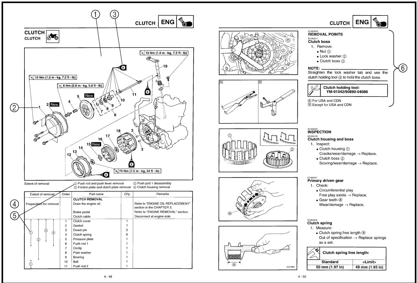
To help identify parts and clarify procedure steps, there are exploded diagrams at the start of each removal and disassembly section.
- An easy-to-see exploded diagram ① is provided for removal and disassembly jobs.
- Numbers ② are given in the order of the jobs in the exploded diagram. A number that is enclosed by a circle indicates a disassembly step.
- An explanation of jobs and notes is presented in an easy-to-read way by the use of symbol marks ③. The meanings of the symbol marks are given on the next page.
- A job instruction chart ④ accompanies the exploded diagram, providing the order of jobs, names of parts, notes in jobs, etc.
- Extent of removal ⑤ is provided in the job instruction chart to save the trouble of an unnecessary removal job.
- For jobs requiring more information, the step-by-step format supplements ⑥ are given in addition to the exploded diagram and job instruction chart.
ILLUSTRATED SYMBOLS (Refer to the illustration)
Illustrated symbols ① to ⑦ are designed as thumb tabs to indicate the chapter's number and content.
① General information
② Specifications
③ Regular inspection and adjustments
④ Engine
⑤ Chassis
⑥ Electrical
⑦ Tuning
Illustrated symbols ⑧ to ⑭ are used to identify the specifications appearing in the text.
⑧ With engine mounted
⑨ Special tool
⑩ Filling fluid
⑪ Lubricant
⑫ Tightening
⑬ Specified value, Service limit
⑭ Resistance (Ω), Voltage (V), Electric current (A)
Illustrated symbols ⑮ to ⑱ in the exploded diagrams indicate grade of lubricant and location of lubrication point.
⑮ Apply engine oil
⑯ Apply molybdenum disulfide oil
⑰ Apply lightweight lithium-soap base grease
⑱ Apply molybdenum disulfide grease
Illustrated symbols ⑲ to ⑳ in the exploded diagrams indicate where to apply a locking agent and where to install new parts.
⑲ Apply locking agent (LOCTITE®)
⑳ Use new one
SYMBOLES GRAPHIQUES (Voir l'illustration)
CHECKING OF CONNECTION 1-6
SPECIAL TOOLS 1-7
CONTROL FUNCTIONS ...... 1-10
MULTI-FUNCTION DISPLAY 1-14
FUEL 1-21
STARTING AND BREAK-IN 1-22
TORQUE-CHECK POINTS 1-26
CLEANING AND STORAGE 1-27
CHAPTER 2
SPECIFICATIONS
GENERAL SPECIFICATIONS ......2-1
MAINTENANCE SPECIFICATIONS .....2-4
GENERAL TORQUE
SPECIFICATIONS 2-20
DEFINITION OF UNITS ......2-20
LUBRICATION DIAGRAMS ......2-21
CABLE ROUTING DIAGRAM ......2-23
CHAPTER 3
REGULAR INSPECTION AND
ADJUSTMENTS
MAINTENANCE INTERVALS ......3-1
CONNEXIONS ...... 1-6
OUTILS SPECIAUX.... 1-7
FONCTIONS DES
COMMANDES 1-10
ECRAN MULTIFONCTION...... 1-14
CARBURANT......1-21
MISE EN MARCHE ET
RODAGE....1-22
POINTS DE VERIFICATION
DES COUPLES
DE SERRAGE 1-26
NETTOYAGE ET REMISAGE... 1-27
CHAPITRE 2 CARACTERISTIQUES
CARACTERISTIQUES
GENERALES....2-1
CARACTERISTIQUES
D'ENTRETIEN 2-4
CARACTERISTIQUES
GENERALES DE COUPLE ..... 2-20
DEFINITION DES UNITES ...... 2-20
DIAGRAMMES
DE LUBRIFICATION ...... 2-21
DIAGRAMME
DE CHEMINEMENT
DES CABLES 2-23
CHAPITRE 3 CONTROLES ET REGLAGES PERIODIQUES
PROGRAMME D'ENTRETIEN ... 3-1
CONTROLE ET ENTRETIEN
AVANT UTILISATION ...... 3-4
MOTEUR 3-5
CHASSIS 3-25
PARTIE ELECTRIQUE ...... 3-48
INHALT
KICK AXLE AND SHIFT SHAFT .....4-74
AC MAGNETO
AND STARTER CLUTCH 4-82
ENGINE REMOVAL 4-89
CRANKCASE AND CRANKSHAFT .....4-95
TRANSMISSION, SHIFT CAM
AND SHIFT FORK 4-104
CHAPTER 5 CHASSIS
FRONT WHEEL AND REAR WHEEL .....5-1
FRONT BRAKE AND REAR BRAKE .....5-10
FRONT FORK 5-26
HANDLEBAR 5-39
STEERING 5-46
SWINGARM 5-52
REAR SHOCK ABSORBER 5-60
CHAPITRE 4 MOTEUR
SELLE, RESERVOIR
DE CARBURANT
ET CACHES LATERAUX......4-1
TUBE D'ECHAPPEMENT
ET SILENCIEUX 4-3
RADIATEUR 4-5
CARBURATEUR 4-8
SYSTEME D'INDUCTION
D'AIR......4-22
ARBRES A CAMES....4-24
CULASSE......4-33
SOUPAPES ET RESSORTS
DE SOUPAPES......4-37
CYLINDRE ET PISTON......4-46
EMBRAYAGE......4-52
FILTRE A HUILE, POMPE
A EAU ET COUVERCLE
DE CARTER MOTEUR
(DROIT) 4-59
BALANCIER 4-66
POMPE A HUILE 4-70
CHAPITRE 7 MISE AU POINT
MOTEUR 7-1
CHASSIS 7-9
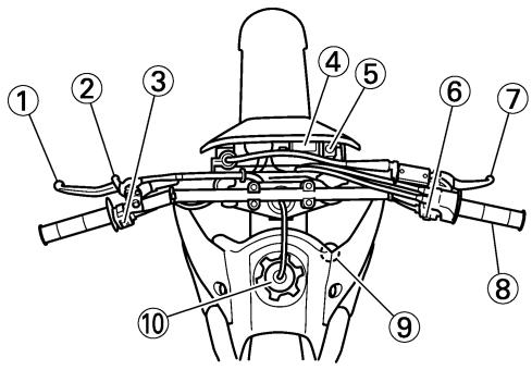
① Clutch lever
② Hot starter lever
③ “ENGINE STOP” button
④ Multi-function display
⑤ Main switch
⑥ Start switch
⑦ Front brake lever
⑧ Throttle grip
⑨ Radiator cap
⑩ Fuel tank cap
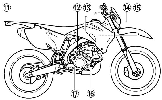
⑪ Taillight
⑫ Kickstarter
⑬ Fuel tank
⑭ Headlight
⑮ Radiator
⑯ Coolant drain bolt
⑰ Rear brake pedal
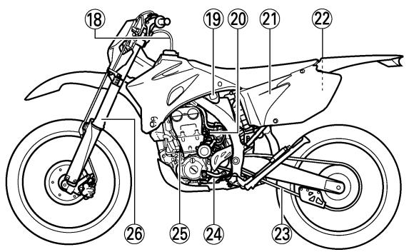
⑱ Valve joint
⑲ Fuel cock
⑳ Cold starter knob
②1 Air cleaner
② Catch tank
②3 Drive chain
⑳ Shift pedal
⑲ Oil dipstick
⑳ Front fork
NOTE:
- The machine you have purchased may differ slightly from those shown in the following.
- Designs and specifications are subject to change without notice.
RENSEIGNEMENTS GENERAUX DESCRIPTION
There are two significant reasons for knowing the serial number of your machine:
- When ordering parts, you can give the number to your Yamaha dealer for positive identification of the model you own.
- If your machine is stolen, the authorities will need the number to search for and identify your machine.
EC121001
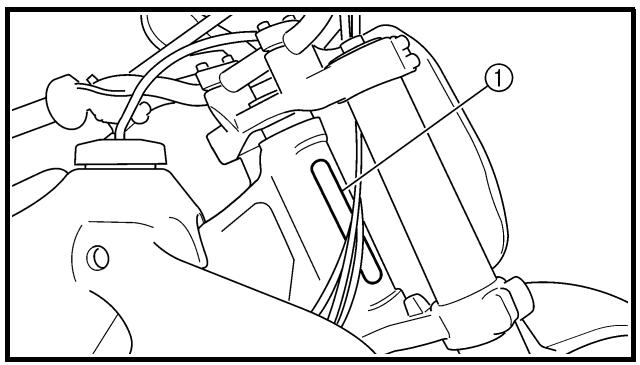
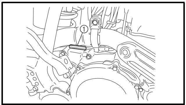
VEHICLE IDENTIFICATION NUMBER
The vehicle identification number ① is stamped on the right of the steering head pipe.
natural_image
Technical line drawing of a mechanical assembly with labeled component (1), no readable text or symbols present
natural_image
Technical line drawing of a mechanical assembly with no visible text or symbols
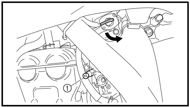
EC123001
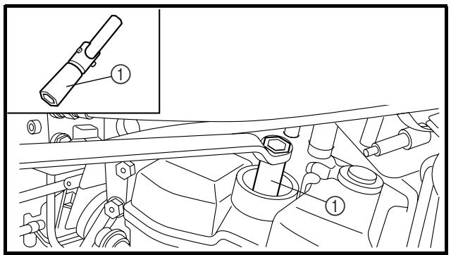
ENGINE SERIAL NUMBER
The engine serial number ① is stamped into the elevated part of the right-side of the engine.
EC124000
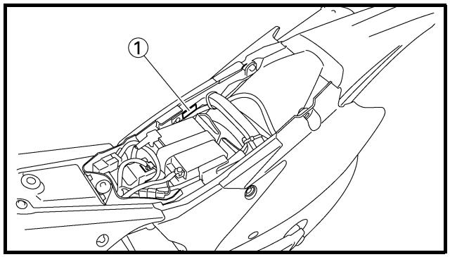
MODEL LABEL
The model label ① is affixed to the frame under the rider's seat. This information will be needed to order spare parts.
IDENTIFICATION DE LA MOTO
-
Remove all dirt, mud, dust, and foreign material before removal and disassembly. When washing the machine with high pressured water, cover the parts as follows.
-
Silencer exhaust port
- Side cover air intake port
• Water pump housing hole at the bottom
- Drain hole on the cylinder head (right side)
-
All electrical components
-
Use proper tools and cleaning equipment. Refer to "SPECIAL TOOLS" section.
- When disassembling the machine, keep mated parts together. They include gears, cylinders, pistons, and other mated parts that have been “mated” through normal wear. Mated parts must be reused as an assembly or replaced.
- During the machine disassembly, clean all parts and place them in trays in the order of disassembly. This will speed up assembly time and help assure that all parts are correctly reinstalled.
- Keep away from fire.
PREPARATION A LA DEPOSE ET AU DEMONTAGE
ALL REPLACEMENT PARTS
- We recommend to use Yamaha genuine parts for all replacements. Use oil and/or grease recommended by Yamaha for assembly and adjustment.
EC133000
GASKETS, OIL SEALS AND O-RINGS
- All gaskets, oil seals, and O-rings should be replaced when an engine is overhauled. All gasket surfaces, oil seal lips, and O-rings must be cleaned.
- Properly oil all mating parts and bearings during reassembly. Apply grease to the oil seal lips.
EC134000
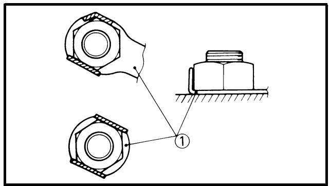
LOCK WASHERS/PLATES AND COTTER PINS
- All lock washers/plates ① and cotter pins must be replaced when they are removed. Lock tab(s) should be bent along the bolt or nut flat(s) after the bolt or nut has been properly tightened.
EC135001
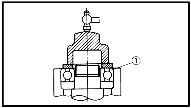
BEARINGS AND OIL SEALS
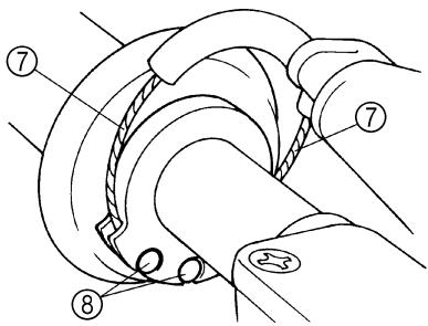
- Install the bearing(s) ① and oil seal(s) ② with their manufacturer's marks or numbers facing outward. (In other words, the stamped letters must be on the side exposed to view.) When installing oil seal(s), apply a light coating of light-weight lithium base grease to the seal lip(s). Oil the bearings liberally when installing.
CAUTION:
Do not use compressed air to spin the bearings dry. This causes damage to the bearing surfaces.
PIECES DE RECHANGE
EC136000
CIRCLIPS
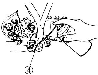
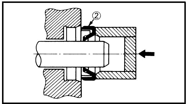
- All circlips should be inspected carefully before reassembly. Always replace piston pin clips after one use. Replace distorted circlips. When installing a circlip ①, make sure that the sharp-edged corner ② is positioned opposite to the thrust ③ it receives. See the sectional view.
④ Shaft
CIRCLIPS
natural_image
Two-panel line drawing showing a hand holding a tool, with no text or symbols present.
natural_image
Diagram of electrical testing setup with wires, probes, and a multimeter (no text or symbols)
natural_image
Diagram of a hand connecting two cables to a multimeter connected by a cable (no text or symbols present)
EC1C0001
CHECKING OF CONNECTION
Dealing with stains, rust, moisture, etc. on the connector.
- Disconnect:
- Connector
-
Dry each terminal with an air blower.
-
Connect and disconnect the connector two or three times.
-
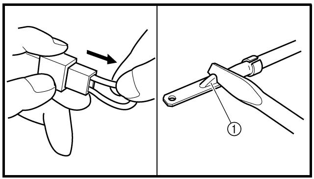
Pull the lead to check that it will not come off.
-
If the terminal comes off, bend up the pin ① and reinsert the terminal into the connector.
-
Connect:
- Connector
NOTE:
The two connectors "click" together.
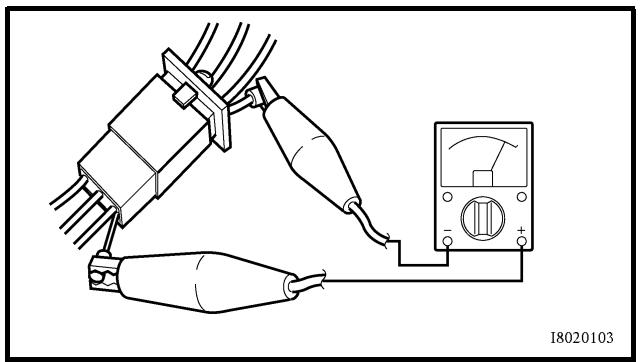
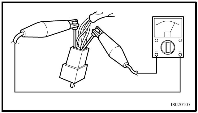
- Check for continuity with a tester.
NOTE:
- If there in no continuity, clean the terminals.
- Be sure to perform the steps 1 to 7 listed above when checking the wire harness.
- For a field remedy, use a contact revitalizer available on the market.
- Use the tester on the connector as shown.
VERIFICATION DES CONNEXIONS
The proper special tools are necessary for complete and accurate tune-up and assembly. Using the correct special tool will help prevent damage caused by the use of improper tools or improvised techniques. The shape and part number used for the special tool differ by country, so two types are provided. Refer to the list provided to avoid errors when placing an order.
NOTE:
- For U.S.A. and Canada, use part number starting with "YM-", "YU-" or "ACC-".
- For others, use part number starting with "90890-".
| Part number | Tool name/How to use | Illustration |
| YU-3097, 90890-01252YU-1256 | Dial gauge and standStandThese tools are used to check each part for runout or bend. | YU-3097YU-1256 | 90890-01252 |
| YU-90050, 90890-01274YU-90050, 90890-01275YM-91044, 90890-04081YU-90063, 90890-01278 | Crankshaft installing toolCrankshaft installing potCrankshaft installing boltSpacer (crankshaft installer)Adapter (M12)These tools are used to install the crankshaft. | YU-90050YU-90063YM-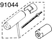 | 90890-0127490890-90890-90890-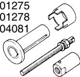 |
| YU-1304, 90890-01304 | Piston pin pullerThis tool is used to remove the piston pin. | YU-1304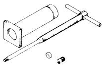 | 90890-01304 |
| YU-24460-01, 90890-01325YU-33984, 90890-01352 | Radiator cap testerAdapterThese tools are used for checking the cooling system. | YU-24460-01YU-33984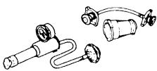 | 90890-0132590890-01352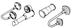 |
| YU-33975, 90890-01403 | Ring nut wrenchThis tool is used when tighten the steering ring nut to specification. | YU-33975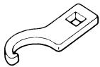 | 90890-01403 |
| YM-01494, 90890-01494 | Damper rod holderUse this tool to remove and install the damper rod. | YM-01494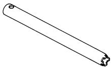 | 90890-01494 |
| YM-A0948, 90890-01502 | Fork seal driverThis tool is used when install the fork oil seal. | YM-A0948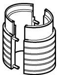 | 90890-01502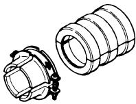 |
| YS-1880-A, 90890-01701 | Sheave holderThis tool is used for when loosening or tightening the flywheel magneto securing nut. | YS-1880-A | 90890-01701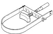 |
| YU-3112-C, 90890-03112 | Pocket testerUse this tool to inspect the coil resistance, output voltage and amperage. | YU-3112-C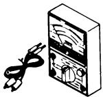 | 90890-03112 |
| YM-33277-A, 90890-03141 | Timing lightThis tool is necessary for checking ignition timing. | YM-33277-A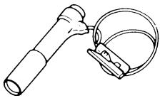 | 90890-03141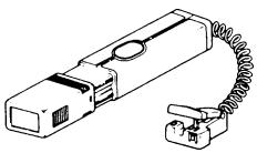 |
| YM-4019, 90890-04019 | Valve spring compressorThis tool is needed to remove and install the valve assemblies. | YM-4019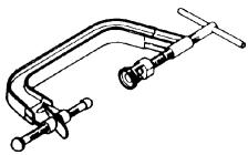 | 90890-04019 |
| YM-91042, 90890-04086 | Clutch holding toolThis tool is used to hold the clutch when removing or installing the clutch boss securing nut. | YM-91042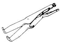 | 90890-04086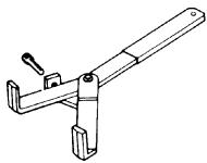 |
| YM-4116, 90890-04116YM-4097, 90890-04097 | Valve guide removerIntake 4.5 mm (0.18 in)Exhaust 5.0 mm (0.20 in)This tool is needed to remove and install the valve guide. | YM-4116YM-4097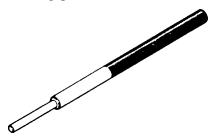 | 90890-0411690890-04097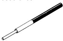 |
| YM-4117, 90890-04117YM-4098, 90890-04098 | Valve guide installerIntakeExhaustThis tool is needed to install the valve guide. | YM-4117YM-409 | 90890-0411790890-(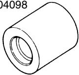 |
| YM-4118, 90890-04118YM-4099, 90890-04099 | Valve guide reamerIntake 4.5 mm (0.18 in)Exhaust 5.0 mm (0.20 in)This tool is needed to rebore the new valve guide. | YM-4118 2G82 | 90890-04118§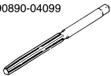 |
| YM-04142, 90890-04142 | Rotor pullerThis tool is used to remove the flywheel magneto. | YM-04142 | 90890-04142 |
| YU-A9642, 90890-04152 | Crankcase separating toolThese tool is used to remove the crankshaft from either case. | YU-A9642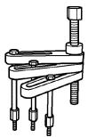 | 90890-04152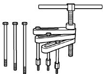 |
| YM-3448790890-06754 | Dynamic spark testerIgnition checkerThis instrument is necessary for checking the ignition system components. | YM-34487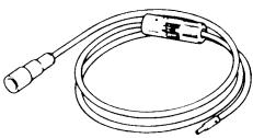 | 90890-06754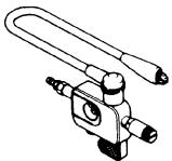 |
| YB-35956-A, 90890-06756 | Vacuum/pressure pump gauge setThis tool is used to check the air induction system. | YB-35956-A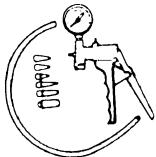 | 90890-06756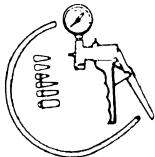 |
| 90890-85505 | YAMAHA Bond No. 1215(ThreeBond® No. 1215)This sealant (Bond) is used for crankcase mating surface, etc. | 90890-85505 | 90890-85505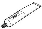 |
OUTILS SPECIAUX
EC150000
CONTROL FUNCTIONS
MAIN SWITCH
Functions of the respective switch positions are as follows:
ON:
The engine can be started only at this position.
OFF:
All electrical circuits are switched off.
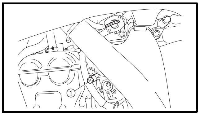
Main switch indicator light
The main switch ① is equipped with an indicator light ② to avoid forgetting to turn it off. This light functions as follows.
- It lights up with the main switch "ON".
- It goes out when the engine increases its speed after being started.
- It lights up again when the engine is stopped.
NOTE:
If the indicator light will not light up with the main switch "ON", it shows a lack of the battery voltage. Recharge the battery.
natural_image
Technical line drawing of a mechanical device with labeled component (1), no readable text or symbols present.
EC151000
The “ENGINE STOP” button ① is located on the left handlebar. Continue pushing the “ENGINE STOP” button till the engine comes to a stop.
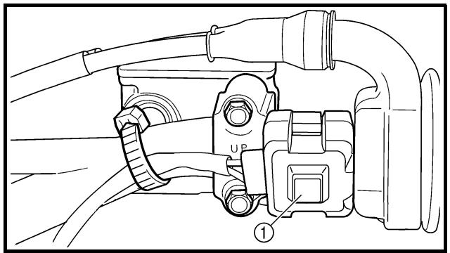
START SWITCH
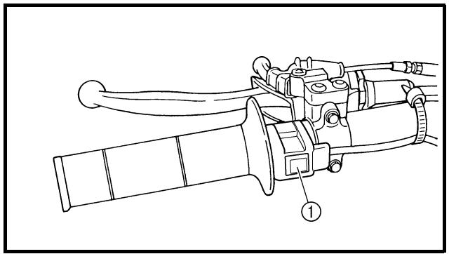
The start switch ① is located on the right handlebar. Push this switch to crank the engine with the starter.
FONCTIONS DES COMMANDES
EC152000
CLUTCH LEVER
The clutch lever ① is located on the left handlebar; it disengages or engages the clutch. Pull the clutch lever to the handlebar to disengage the clutch, and release the lever to engage the clutch. The lever should be pulled rapidly and released slowly for smooth starts.
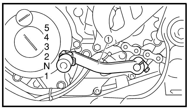
EC153000
SHIFT PEDAL
The gear ratios of the constant-mesh 5 speed transmission are ideally spaced. The gears can be shifted by using the shift pedal ① on the left side of the engine.
EC154000
KICKSTARTER
Rotate the kickstarter ① away from the engine. Push the starter down lightly with your foot until the gears engage, then kick smoothly and forcefully to start the engine. This model has a primary kickstarter so the engine can be started in any gear if the clutch is disengaged. In normal practices, however, shift to neutral before starting.
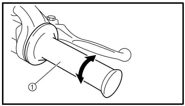
EC155001
THROTTLE GRIP
The throttle grip ① is located on the right handlebar; it accelerates or decelerates the engine. For acceleration, turn the grip toward you; for deceleration, turn it away from you.
EC156000
FRONT BRAKE LEVER
The front brake lever ① is located on the right handlebar. Pull it toward the handlebar to activate the front brake.
LEVIER D'EMBRAYAGE
The rear brake pedal ① is located on the right side of the machine. Press down on the brake pedal to activate the rear brake.
FUEL COCK
The fuel cock supplies fuel from the tank to carburetor and also filters the fuel. The fuel cock has three positions:
OFF: With the lever in this position fuel will not flow. Always return the lever to this position when the engine is not running.
ON: With the lever in this position fuel flows to the carburetor. Normal riding is done with the lever in this position.
RES: With the lever in this position fuel flows to the carburetor from the reserve section of the fuel tank after the main supply of the fuel has been depleted. Normal riding is possible with the lever is in this position, but it is recommended to add fuel as soon as possible.
natural_image
Technical line drawing of a car interior showing dashboard, steering wheel, and gear mechanism (no text or symbols)
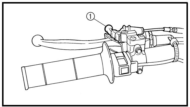
COLD STARTER KNOB
When cold, the engine requires a richer air-fuel mixture for starting. A separate starter circuit, which is controlled by the cold starter knob ①, supplies this mixture. Pull the cold starter knob out to open the circuit for starting. When the engine has warmed up, push it in to close the circuit.
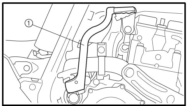
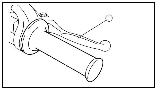
HOT STARTER LEVER
The hot starter lever ① is used when starting a warm engine.
Use the hot starter lever when starting the engine again immediately after it was stopped (the engine is still warm). Pulling the hot starter lever injects secondary air to thin the air-fuel mixture temporarily, allowing the engine to be started more easily.
PEDALE DE FREIN ARRIERE
SIDESTAND
This sidestand ① is used to support only the machine when standing or transporting it.
WARNING
- Never apply additional force to the side-stand.
- Hold up the sidestand before starting out.
EC15F000
VALVE JOINT
This valve joint ① prevents fuel from flowing out and is installed to the fuel tank breather hose.
CAUTION:
In this installation, make sure the arrow faces the fuel tank and also downward.
SPARK PLUG WRENCH
This spark plug wrench ① is used to remove and install the spark plug.
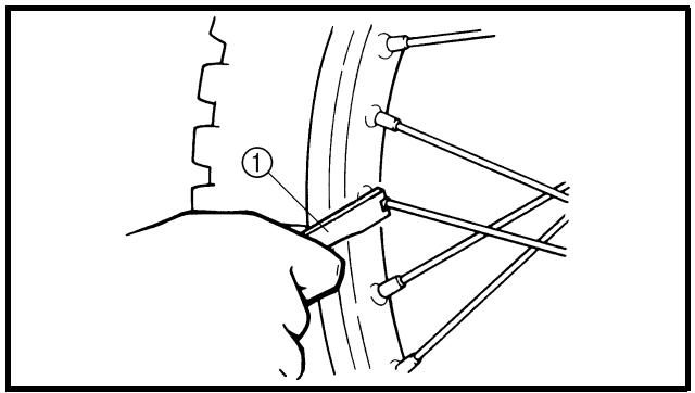
NIPPLE WRENCH
This nipple wrench ① is used to tighten the spoke.
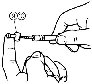
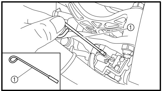
The jet needle pull-up tool ① is used to pull the jet needle out of the carburetor.
BEQUILLE LATERALE
MULTI-FUNCTION DISPLAY
WARNING
Be sure to stop the machine before making any setting changes to the multi-function display.
The multi-function display is equipped with the following:
BASIC MODE:
- Speedometer
- Clock
- Two tripmeters (which shows the distance that has been traveled since it was last set to zero)
RACE MODE:
- Timer (which shows the time that has been accumulated since the start of timer measurement)
- Tripmeter (which shows the accumulated travel distance in timer measurement)
- Change tripmeter digits (capable of change to any given ones)
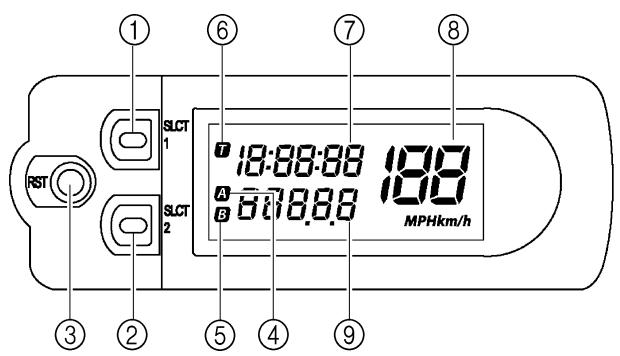
DESCRIPTION
① Select button "SLCT 1"
② Select button "SLCT 2"
③ Reset button "RST"
Screen display:
④ Tripmeter indicator A
⑤ Tripmeter indicator B
⑥ Timer indicator T
⑦ Clock/Timer
⑧ Speedometer
⑨ Odometer/Tripmeter
NOTE:
The operation buttons can be pushed in the following two manners:
Short push: Push the button. (☐)
Long push: Push the button for 2 seconds or more. (→)
ECRAN MULTIFONC-TION
! AVERTISSEMENT
flowchart
graph TD
    A["RST"] --> B["SLCT1"]
    A --> C["SLCT2"]
    B --> D["12:00:00"]
    C --> D
    D --> E["12:00:00"]
    E --> F["RST"]
    style A fill:#f9f,stroke:#333
    style D fill:#ccf,stroke:#333
    style E fill:#cfc,stroke:#333
flowchart
graph TD
    A["+"] --> B["SLCT1"]
    B --> C["SLCT2"]
    C --> D["-"]
    style A fill:#fff,stroke:#000
    style B fill:#fff,stroke:#000
    style C fill:#fff,stroke:#000
    style D fill:#fff,stroke:#000
    subgraph Display
        E["12:00:00 A 10.0 MPH"] --> F["Digital Display"]
BASIC MODE
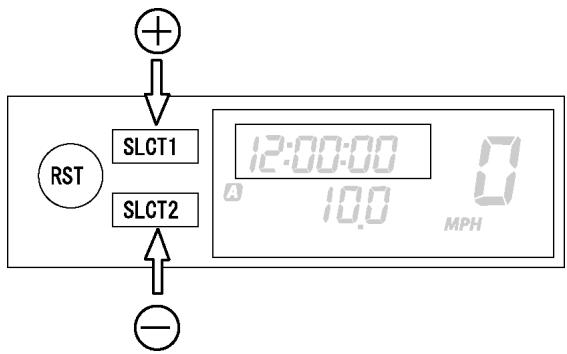
Changing speedometer display (for U.K.)
- Push the "SLCT2" button for 2 seconds or more to change the speedometer units.
The speedometer display will change in the following order:
MPH → km/h → MPH.
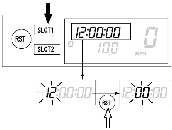
Setting the time
- Push the "SLCT1" button for 2 seconds or more to enter the time setting mode.
- Push the "RST" button to change the display for time indication. The display will change in the following order:
Hour → Minute → Second → Hour.
NOTE:
The digits capable of setting go on flashing.
-
Push the "SLCT1" button (plus) or "SLCT2" button (minus) and change the time. A long push on the button will fast-forward the time.
-
To end the setting, push the "RST" button for 2 seconds or more.
NOTE:
- In a 30-second absence of button operation, the setting will come to an end with the indicated time.
- To reset the seconds, push the "SLCT1" button or "SLCT2" button.
MODE DE BASE
flowchart
graph TD
    A["SLCT1"] --> B["12:00:00 MPH"]
    C["SLCT2"] --> B
    B --> D["0 1025"]
    D --> E["A 10.0"]
    E --> F["B 20.0"]
    F --> G["RST"]
    G --> H["SLCT1"]
    G --> I["SLCT2"]
    H --> J["12:00:00 MPH"]
    I --> J
    J --> K["A 10.0"]
    K --> L["A 0.0"]
flowchart
graph TD
    A["SLCT1"] --> B["12:00:00"]
    C["SLCT2"] --> D["10.0"]
    B --> E["MPH"]
    D --> E
    F["RST"] --> G["SLCT1"]
    F --> H["SLCT2"]
    G --> I["0:00:00"]
    H --> J["0.0"]
    I --> K["MPH"]
Changing odometer and tripmeter A/B (TRIP A/B)
- Push the "SLCT2" button to change the tripmeter display. The display will change in the following order:
Odometer → TRIP A → TRIP B → TRIP A → Odometer.
NOTE:
To reset the digits, select the tripmeter involved and push the "RST" button for 2 seconds or more.
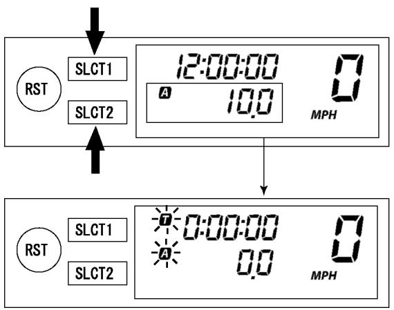
CHANGEOVER TO BASIC MODE/RACE MODE
NOTE:
- Measurement using the timer function can be made in RACE MODE.
- Indicator T will light up as an identifier that shows RACE MODE has been selected.
- RACE MODE cannot display the functions as in BASIC MODE.
- Changeover to RACE MODE forces the digits for tripmeter A (TRIP A) in BASIC MODE to be reset.
Changeover from BASIC MODE to RACE MODE
- Push the "SLCT1" button and "SLCT2" button for 2 seconds or more at the same time to change over to RACE MODE.
NOTE:
Changeover to RACE MODE will put manual start measurement on standby causing T and A to flash. (For manual start, refer to "Putting measurement on standby" in "RACE MODE".)
flowchart
graph TD
    A["RST"] --> B["SLCT1"]
    A --> C["SLCT2"]
    B --> D["T 0: 15:08 A 10.3 MPH"]
    C --> D
    E["RST"] --> F["SLCT1"]
    E --> G["SLCT2"]
    F --> H["T 0:00:00 A 0.0 MPH"]
    G --> H
    H --> I["12:00:00 A 0.0 MPH"]
Returning to BASIC MODE from RACE MODE
NOTE:
It is possible to return to BASIC MODE with timer measurement at a stop.
- Check that the timer is not in operation. If the timer is in operation, stop the timer by pushing the "SLCT1" button and "SLCT2" button at the same time.
- Push the "SLCT1" button and "SLCT2" button for 2 seconds or more at the same time to change over to BASIC MODE.
RACE MODE
Putting measurement on standby
NOTE:
Starting measurement consists of the following two starts, either of which can be selected.
- Manual start
Starting measurement by the rider himself operating the button. (A long push on “SLCT2” button will put measurement on standby.)
- Auto start
Starting timer measurement automatically on detection of the movement of the machine. (A long push on "SLCT1" button will put measurement on standby.)
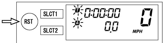
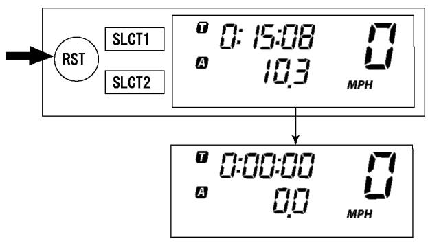
Manual start
NOTE:
Initial setting at changeover to RACE MODE will remain for manual start.
- Check that changeover to RACE MODE has been made. (Refer to “Changeover from BASIC MODE to RACE MODE”.)
NOTE:
When the machine is made ready for a run by manual start, T and A will start flashing.
flowchart
graph TD
    A["RST"] --> B["SLCT1"]
    A --> C["SLCT2"]
    B --> D["0: 15:08 A 10.3 MPH"]
    C --> E["0:00:00 A 0.0 MPH"]
    E --> F["0:00:00 A 0.0 MPH"]
    F --> G["0:15:08 A 10.3 MPH"]
- Start timer measurement by pushing the "RST" button.
- When stopping timer measurement, pushing the "SLCT1" button and "SLCT2" button at the same time.
NOTE:
If the machine is run while timer measurement is not made, no change will occur to the digit in tripmeter A (TRIP A).
- To resume the measurement, again push the "SLCT1" button and "SLCT2" button at the same time.
Auto start
- Check that changeover has been made to RACE MODE. (Refer to "Changeover from BASIC MODE to RACE MODE".)
- Make the machine ready for a run by pushing the "SLCT1" button for 2 seconds or more.
NOTE:
When measurement is made ready for a run by auto start, T and A will start flashing. Timer display will turn on scrolling from left to right.
- Run the machine and start timer measurement.
- To stop timer measurement, pushing the "SLCT1" button and the "SLCT2" button at the same time.
NOTE:
If the machine is run while timer measurement is not made, no change will occur to the digit in tripmeter A (TRIP A).
flowchart
graph TD
    A["RST"] --> B["SLCT1"]
    A --> C["SLCT2"]
    B --> D["0:15:08"]
    C --> E["A 10.3 MPH"]
    D --> F["0:15:08"]
    E --> F
    G["0:15:08"] --> H["A -0.0 MPH"]
flowchart
graph TD
    A["RST"] --> B["SLCT1"]
    A --> C["SLCT2"]
    B --> D["0: 15:08"]
    C --> E["A 10.3 MPH"]
    D --> F["0:00:00"]
    E --> F
    G["0:00:00"] --> H["A 0.0 MPH"]
flowchart
graph TD
    A["+"] --> B["SLCT1"]
    B --> C["RST"]
    C --> D["SLCT2"]
    D --> E["+"]
    E --> F["0:15:08 50 MPH"]
    F --> G["+"]
    G --> H["10.4"]
    H --> I["SLCT2"]
    I --> J["+"]
    J --> K["10.2"]
    K --> L["-"]
Resetting measurement data
NOTE:
Resetting can be made in the following two manners.
Resetting is possible while timer measurement is made:
- Reset tripmeter A.
Resetting is possible while timer measurement is not made:
- Reset tripmeter A and timer.
Resetting tripmeter A (TRIP A)
-
Check that the timer is in operation. If the timer is not in operation, start the timer by pushing the "SLCT1" button and "SLCT2" button at the same time.
-
Reset tripmeter A (TRIP A) display by pushing the "RST" button for 2 seconds or more.
NOTE:
If reset, A and travel distance display will go on flashing for four seconds.
Resetting tripmeter A (TRIP A) and timer
- Check that the timer is not in operation. If the timer is in operation, stop it by pushing the "SLCT1" button and "SLCT2" button at the same time.
- Reset all measured data by pushing the "RST" button for 2 seconds or more.
NOTE:
- Resetting will reset the timer display and travel distance display and put measurement on standby.
- Auto start attempt will put measurement on standby as such. Likewise, manual start attempt will put measurement on standby as such.
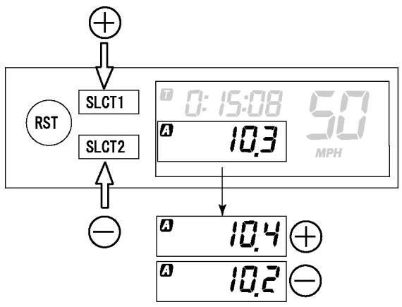
Correcting tripmeter A (TRIP A)
- Change the travel distance display by pushing the "SLCT1" button (plus) or "SLCT2" button (minus). A long push on the button will fast-forward the change.
NOTE:
Change can be made any time while timer measurement is or is not being made.
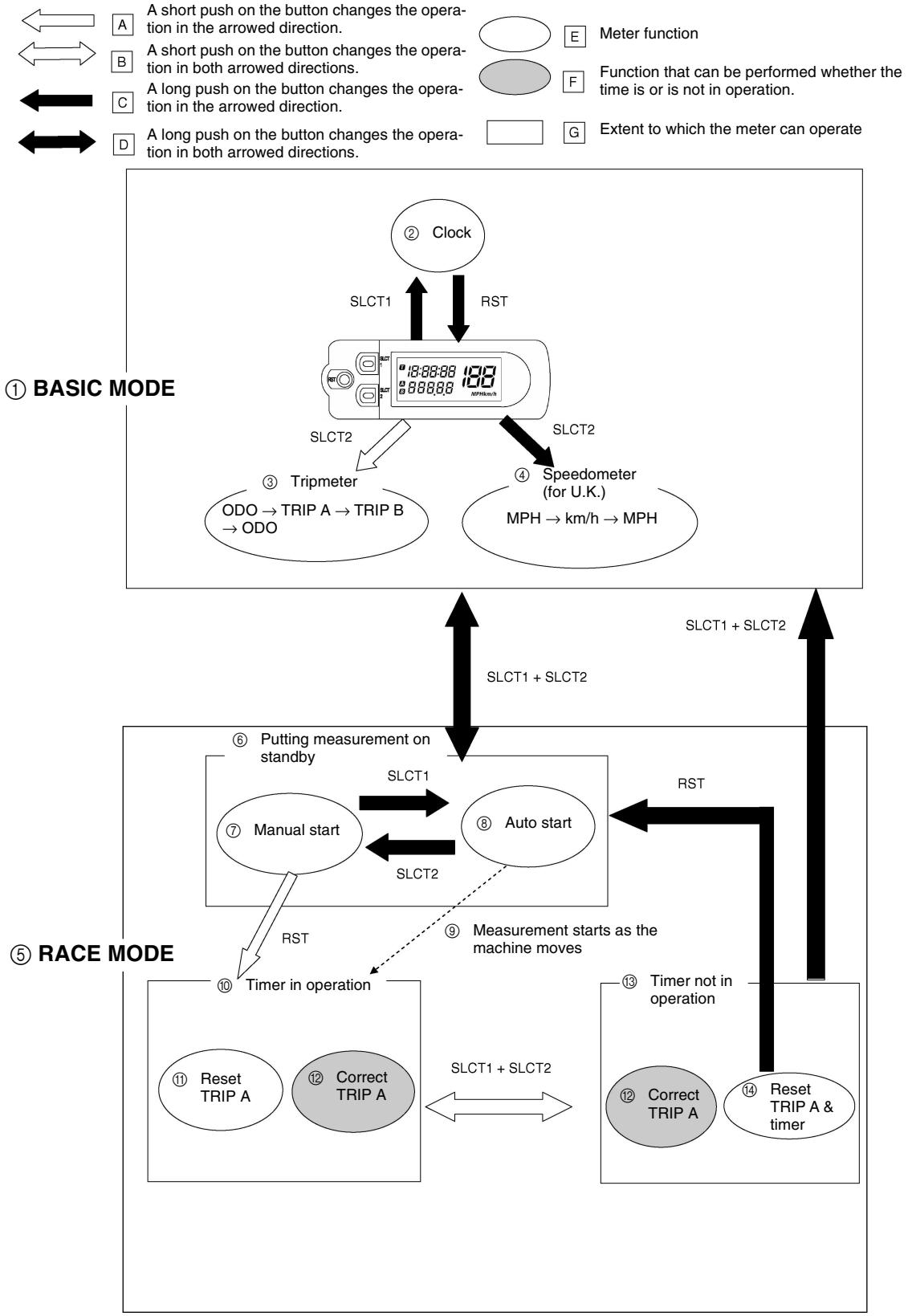
The following diagram illustrates the multi-function display regarding the direction and operation condition involved in each of its functions.
flowchart
graph TD
    A["① BASIC MODE"] --> B["② Clock"]
    B --> C["SLCT1"]
    C --> D["③ Tripmeter"]
    D --> E["ODO → TRIP A → TRIP B → ODO"]
    C --> F["SLCT2"]
    F --> G["④ Speedometer (for U.K.)"]
    G --> H["MPH → km/h → MPH"]
    I["⑤ RACE MODE"] --> J["⑥ Putting measurement on standby"]
    J --> K["Manual start"]
    K --> L["SLCT1 + SLCT2"]
    L --> M["SLCT2"]
    M --> N["⑦ Manual start"]
    N --> O["RST"]
    O --> P["Measurement starts as the machine moves"]
    P --> Q["⑧ Auto start"]
    Q --> R["SLCT1 + SLCT2"]
    R --> S["SLCT2"]
    S --> T["⑨ Measurement starts as the machine moves"]
    T --> U["SLCT1 + SLCT2"]
    V["⑬ Reset TRIP A & timer"] --> W["⑭ Correct TRIP A"]
    W --> X["SLCT1 + SLCT2"]
    X --> Y["SLCT2"]
    Y --> Z["⑮ Timer not in operation"]
    Z --> AA["SLCT1 + SLCT2"]
    AB["A short push on button changes the operation in the arrowed direction."] --> AC["E Meter function"]
    AD["A short push on button changes the operation in both arrowed directions."] --> AE["F Function that can be performed whether the time is or is not in operation."]
    AF["A long push on button changes the operation in the arrowed direction."] --> AG["G Extent to which the meter can operate"]
DIAGRAMME DE FONCTIONNEMENT
N.B.:
Always use the recommended fuel as stated below. Also, be sure to use new gasoline the day of a race.

Recommended fuel: Premium unleaded gasoline only with a research octane number of 95 or higher.
CAUTION:
Use only unleaded gasoline. The use of leaded gasoline will cause severe damage to the engine internal parts such as valves, piston rings, and exhaust system, etc.
NOTE:
If knocking or pinging occurs, use a different brand of gasoline or higher octane grade.
WARNING
- For refueling, be sure to stop the engine and use enough care not to spill any fuel. Also be sure to avoid refueling close to a fire.
- Refuel after the engine, exhaust pipe, etc. have cooled off.
CARBURANT
Never start or run the engine in a closed area. The exhaust fumes are poisonous; they can cause loss of consciousness and death in a very short time. Always operate the machine in a well-ventilated area.
CAUTION:
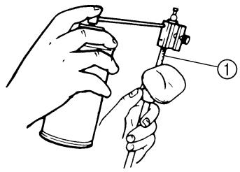
- The carburetor on this machine has a built-in accelerator pump. Therefore, when starting the engine, do not operate the throttle or the spark plug will foul.
- Unlike a two-stroke engine, this engine cannot be kick started when the throttle is open because the kickstarter may kick back. Also, if the throttle is open the air/fuel mixture may be too lean for the engine to start.
- Before starting the machine, perform the checks in the pre-operation check list.
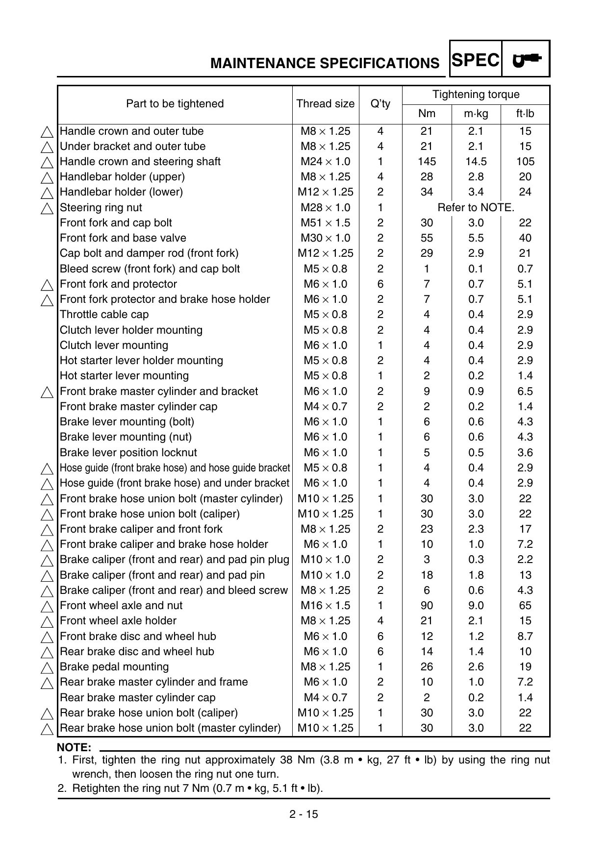
AIR FILTER MAINTENANCE
According to “AIR FILTER CLEANING” section in the CHAPTER 3, apply the foam-air-filter oil or its equivalent to the element. (Excess oil in the element may adversely affect engine starting.)
STARTING A COLD ENGINE
NOTE:
This model is equipped with an ignition circuit cut-off system. The engine can be started under the following conditions.
- When the transmission is in neutral.
- When the clutch is disengaged with the transmission in any position. However, it is recommended to shift into neutral before starting the engine.
- Inspect the coolant level.
- Turn the fuel cock to "ON".
- Push the main switch to "ON".
- Shift the transmission into neutral.
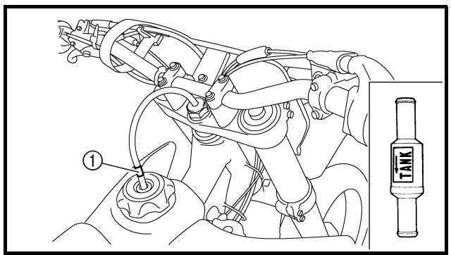
- Fully open the cold starter knob ①.
- Start the engine by pushing the start switch or by kicking the kickstarter.
If the engine fails to start by pushing the start switch, release the switch, wait a few seconds, and then try again. Each starting attempt should be as short as possible to preserve the battery. Do not crank the engine more than 10 seconds on any one attempt. If the engine does not start with the starter motor, try using the kickstarter.
WARNING
- If the starter motor will not turn when pushing the start switch, stop pushing it immediately and kick start the engine in order to avoid the load on the motor.
-
Do not open the throttle while kicking the kickstarter. Otherwise, the kickstarter may kick back.
-
Return the cold starter knob to its original position and run the engine at 3,000 \~ 5,000 r/min for 1 or 2 minutes.
NOTE:
Since this model is equipped with an accelerator pump, if the engine is raced (the throttle opened and closed), the air/fuel mixture will be too rich and the engine may stall. Also unlike a two-stroke engine, this model can idle.
CAUTION:
Do not warm up the engine for extended periods of time.
N.B.:
STARTING A WARM ENGINE
Do not operate the cold starter knob and throttle. Pull the hot starter lever ① and start the engine by pushing the start switch or by kicking the kickstarter forcefully with a firm stroke.
As soon as the engine starts, release the hot starter lever to close the air passage.
Restarting an engine after a fall
Pull the hot starter lever and start the engine. As soon as the engine starts, release the hot starter lever to close the air passage.
The engine fails to start
Pull the hot starter lever all the way out and while holding the lever, kick the kickstarter 10 to 20 times to clear the engine.
Then, restart the engine.
Refer to "Restarting an engine after a fall".
| | Throttle grip operation* | Cold starter knob | Hot starter lever |
| Starting a cold engine | Air temperature = less than 5 °C (41 °F) | Open 3 or 4 times | ON | OFF |
| Air temperature = more than 5 °C (41 °F) | None | ON | OFF |
| Air temperature (normal temperature) = between 5 °C (41 °F) and 25 °C (77 °F) | None | ON/OFF | OFF |
| Air temperature = more than 25 °C (77 °F) | None | OFF | OFF |
| Starting an engine after a long period of time | None | ON | OFF |
| Restarting a warm engine | None | OFF | ON |
| Restarting an engine after a fall | None | OFF | ON |
* Operate the throttle grip before kick starting.
CAUTION:
Observe the following break-in procedures during initial operation to ensure optimum performance and avoid engine damage.
MISE EN MARCHE A CHAUD
- Before starting the engine, fill the fuel tank with the fuel.
- Perform the pre-operation checks on the machine.
- Start and warm up the engine. Check the idle speed, and check the operation of the controls and the "ENGINE STOP" button. Then, restart the engine and check its operation within no more than 5 minutes after it is restarted.
- Operate the machine in the lower gears at moderate throttle openings for five to eight minutes.
- Check how the engine runs when the machine is ridden with the throttle 1/4 to 1/2 open (low to medium speed) for about one hour.
- Restart the engine and check the operation of the machine throughout its entire operating range. Restart the machine and operate it for about 10 to 15 more minutes. The machine will now be ready to race.
CAUTION:
- After the break-in or before each race, you must check the entire machine for loose fittings and fasteners as per "TORQUE-CHECK POINTS".
Tighten all such fasteners as required.
- When any of the following parts have been replaced, they must be broken in. CYLINDER AND CRANKSHAFT:
About one hour of break-in operation is necessary.
PISTON, RING, VALVES, CAMSHAFTS AND GEARS:
These parts require about 30 minutes of break-in operation at half-throttle or less. Observe the condition of the engine carefully during operation.
PROCEDURE DE RODAGE
PISTON, SEGMENT, SOUPAPES,
ARBRES A CAMES ET
PIGNONS:
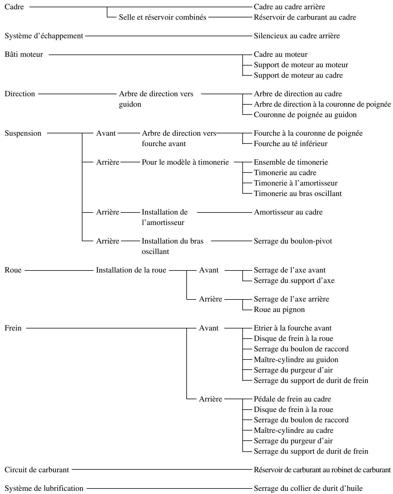
flowchart
graph TD
    A["Frame construction"] --> B["Combined seat and tank"]
    B --> C["Frame to rear frame"]
    B --> D["Fuel tank to frame"]
    E["Exhaust system"] --> F["Silencer to rear frame"]
    G["Engine mounting"] --> H["Frame to engine"]
    H --> I["Engine bracket to engine"]
    H --> J["Engine bracket to frame"]
    K["Steering"] --> L["Steering shaft to handlebar"]
    L --> M["Steering shaft to frame"]
    L --> N["Steering shaft to handle crown"]
    L --> O["Handle crown to handlebar"]
    P["Suspension"] --> Q["Front"]
    P --> R["Steering shaft to front fork"]
    R --> S["Front fork to handle crown"]
    R --> T["Front fork to under bracket"]
    U["Rear"] --> V["For link type"]
    V --> W["Assembly of links"]
    V --> X["Link to frame"]
    V --> Y["Link to shock absorber"]
    V --> Z["Link to swingarm"]
    AA["Rear"] --> AB["Installation of shock absorber"]
    AB --> AC["Shock absorber to frame"]
    AA --> AD["Rear"]
    AD --> AE["Installation of swingarm"]
    AE --> AF["Tightening of pivot shaft"]
    AG["Wheel"] --> AH["Installation of wheel"]
    AH --> AI["Front"]
    AH --> AJ["Rear"]
    AJ --> AK["Tightening of front axle"]
    AJ --> AL["Tightening of axle holder"]
    AJ --> AM["Wheel to sprocket"]
    AN["Brake"] --> AO["Front"]
    AO --> AP["Caliper to front fork"]
    AP --> AQ["Brake disc to wheel"]
    AQ --> AR["Tightening of union bolt"]
    AR --> AS["Master cylinder to handlebar"]
    AR --> AT["Tightening of air bleeder"]
    AR --> AU["Tightening of brake hose holde"]
    AN --> AV["Rear"]
    AV --> AW["Brake pedal to frame"]
    AW --> AX["Brake disc to wheel"]
    AX --> AY["Tightening of union bolt"]
    AY --> AZ["Master cylinder to frame"]
    AZ --> BA["Tightening of air bleeder"]
    AZ --> BB["Tightening of brake hose holde"]
    BC["Fuel system"] --> BD["Fuel tank to fuel cock"]
    BE["Lubrication system"] --> BF["Tightening of oil hose clamp"]
NOTE:
Concerning the tightening torque, refer to "MAINTENANCE SPECIFICATIONS" section in the CHAPTER 2.
POINTS DE VERIFICATION DES COUPLES DE SERRAGE
CLEANING AND STORAGE
EC1B1000
CLEANING
Frequent cleaning of your machine will enhance its appearance, maintain good overall performance, and extend the life of many components.
- Before washing the machine, block off the end of the exhaust pipe to prevent water from entering. A plastic bag secured with a rubber band may be used for this purpose.
- If the engine is excessively greasy, apply some degreaser to it with a paint brush. Do not apply degreaser to the chain, sprockets, or wheel axles.
- Rinse the dirt and degreaser off with a garden hose; use only enough pressure to do the job.
CAUTION:
Excessive hose pressure may cause water seepage and contamination of wheel bearings, front forks, brakes and transmission seals. Many expensive repair bills have resulted from improper high pressure detergent applications such as those available in coin-operated car washers.
- After the majority of the dirt has been hosed off, wash all surfaces with warm water and a mild detergent. Use an old toothbrush to clean hard-to-reach places.
- Rinse the machine off immediately with clean water, and dry all surfaces with a soft towel or cloth.
- Immediately after washing, remove excess water from the chain with a paper towel and lubricate the chain to prevent rust.
- Clean the seat with a vinyl upholstery cleaner to keep the cover pliable and glossy.
NETTOYAGE ET REMISAGE
NETTOYAGE
If your machine is to be stored for 60 days or more, some preventive measures must be taken to avoid deterioration. After cleaning the machine thoroughly, prepare it for storage as follows:
- Drain the fuel tank, fuel lines, and the carburetor float bowl.
- Remove the spark plug, pour a tablespoon of SAE 10W-30 motor oil in the spark plug hole, and reinstall the plug. With the engine stop switch pushed in, kick the engine over several times to coat the cylinder walls with oil.
- Remove the drive chain, clean it thoroughly with solvent, and lubricate it. Reinstall the chain or store it in a plastic bag tied to the frame.
- Lubricate all control cables.
- Block the frame up to raise the wheels off the ground.
- Tie a plastic bag over the exhaust pipe outlet to prevent moisture from entering.
- If the machine is to be stored in a humid or salt-air environment, coat all exposed metal surfaces with a film of light oil. Do not apply oil to rubber parts or the seat cover.
NOTE:
Make any necessary repairs before the machine is stored.
| Model name: | WR450FW (USA, CDN, AUS, NZ)WR450F (EUROPE, ZA) |
| Model code number: | 5TJE (USA)5TJF (EUROPE)5TJG (CDN, AUS, NZ, ZA) |
| Dimensions: | USA, ZA, CDN | EUROPE, AUS, NZ |
| Overall length | 2,175 mm (85.63 in) | 2,190 mm (86.22 in) |
| Overall width | 825 mm (32.48 in) | ← |
| Overall height | 1,295 mm (50.98 in) | 1,300 mm (51.18 in) |
| Seat height | 980 mm (38.58 in) | 990 mm (38.98 in) |
| Wheelbase | 1,485 mm (58.46 in) | ← |
| Minimum ground clearance | 365 mm (14.37 in) | 370 mm (14.57 in) |
| Dry weight:Without oil and fuel | 112.5 kg (248.0 lb) |
| Engine:Engine typeCylinder arrangementDisplacementBore × strokeCompression ratioStarting system | Liquid cooled 4-stroke, DOHCSingle cylinder, forward inclined449 cm3(15.8 Imp oz, 15.2 US oz)95.0 × 63.4 mm (3.74 × 2.50 in)12.3 : 1Kick and electric starter |
| Lubrication system: | Dry sump |
Oil type or grade:Engine oil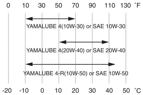 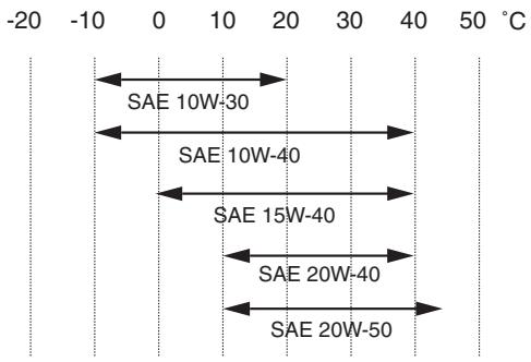 | (For USA and CDN)Yamalube 4, SAE10W30 or SAE20W40Yamalube 4-R, SAE10W50API service SG type or higher,JASO standard MA(Except for USA and CDN)SAE10W30, SAE10W40, SAE15W40,SAE20W40 or SAE20W50API service SG type or higher,JASO standard MA |
| Oil capacity:Engine oilPeriodic oil changeWith oil filter replacementTotal amount | 0.95 L (0.84 Imp qt, 1.00 US qt)1.0 L (0.88 Imp qt, 1.06 US qt)1.2 L (1.06 Imp qt, 1.27 US qt) |
| Coolant capacity (including all routes): | 1.0 L (0.88 Imp qt, 1.06 US qt) |
| Air filter: | Wet type element |
| Fuel:TypeTank capacityReserve | Premium unleaded gasoline only with a research octane number of 95 or higher.8.0 L (1.76 Imp gal, 2.11 US gal)1.1 L (0.24 Imp gal, 0.29 US gal) |
| Carburetor:TypeManufacturer | FCR MX39KEIHIN |
| Spark plug:Type/manufacturerGap | CR8E/NGK (resistance type)0.7 ~ 0.8 mm (0.028 ~ 0.031 in) |
| Clutch type: | Wet, multiple-disc |
| Transmission:Primary reduction systemPrimary reduction ratioSecondary reduction systemSecondary reduction ratioTransmission typeOperationGear ratio: 1st2nd3rd4th5th | Gear61/23 (2.652)Chain drive50/13 (3.846)Constant mesh, 5-speedLeft foot operation29/12 (2.417)26/15 (1.733)21/16 (1.313)21/20 (1.050)21/25 (0.840) |
| Chassis:Frame typeCaster angleTrail | USA, ZA, CDN | EUROPE, AUS, NZ |
| Semi double cradle27.3°117 mm (4.61 in) | ←27.0°116 mm (4.57 in) |
| Tire:TypeSize (front)Size (rear)Tire pressure (front and rear) | With tube80/100-21 51M (USA, CDN, ZA)90/90-21 54R (EUROPE, AUS, NZ)110/100-18 64M (USA, CDN, ZA)130/90-18 69R (EUROPE, AUS, NZ)100 kPa (1.0 kgf/cm2, 15 psi) |
| Brake: | |
| Front brake type | Single disc brake |
| Operation | Right hand operation |
| Rear brake type | Single disc brake |
| Operation | Right foot operation |
| Suspension: | |
| Front suspension | Telescopic fork |
| Rear suspension | Swingarm (link type monocross suspension) |
| Shock absorber: | |
| Front shock absorber | Coil spring/oil damper |
| Rear shock absorber | Coil spring/gas, oil damper |
| Wheel travel: | |
| Front wheel travel | 300 mm (11.8 in) |
| Rear wheel travel | 305 mm (12.0 in) |
| Electrical: | |
| Ignition system | CDI |
| Generator system | AC magneto |
| Battery type | YTZ7S |
| Battery voltage/capacity | 12 V/6 AH |
| Specific gravity | 1.310 |
| Headlight type: | Quartz bulb (halogen) |
| Bulb wattage × quantity: | |
| Headlight | 12 V 35/36.5 W × 1 |
| Taillight | 12 V 1.6/0.3 W × 1 |
MAINTENANCE SPECIFICATIONS
ENGINE
| Item | Standard | Limit |
Cylinder head:Warp limit | ---- | 0.05 mm(0.002 in) |
| Cylinder:Bore sizeOut of round limit | 95.00 ~ 95.01 mm(3.7402 ~ 3.7406 in)---- | ----0.05 mm(0.002 in) |
Camshaft:Drive methodCamshaft cap inside diameterCamshaft journal diameterShaft-to-cap clearanceCam dimensions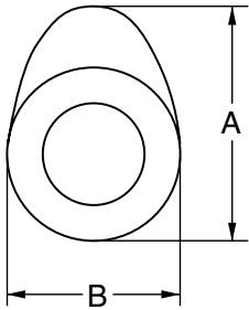 | Chain drive (Left)22.000 ~ 22.021 mm(0.8661 ~ 0.8670 in)21.959 ~ 21.972 mm(0.8645 ~ 0.8650 in)0.028 ~ 0.062 mm(0.0011 ~ 0.0024 in) | --------0.08 mm(0.003 in) |
| Intake | “A” | 30.100 ~ 30.200 mm(1.1850 ~ 1.1890 in) | 30.000 mm(1.1811 in) |
| “B” | 22.450 ~ 22.550 mm(0.8839 ~ 0.8878 in) | 22.350 mm(0.8799 in) |
| Exhaust | “A” | 30.200 ~ 30.300 mm(1.1890 ~ 1.1929 in) | 30.100 mm(1.1850 in) |
| “B” | 22.450 ~ 22.550 mm(0.8839 ~ 0.8878 in) | 22.350 mm(0.8799 in) |
Camshaft runout limit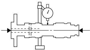 | ---- | 0.03 mm(0.0012 in) |
| Cam chain: | | | |
| Cam chain type/No. of links | | 98XRH2010-118M/118 | ---- |
| Cam chain adjustment method | | Automatic | ---- |
| Valve, valve seat, valve guide: | | | |
| Valve clearance (cold) | IN | 0.10 ~ 0.15 mm(0.0039 ~ 0.0059 in) | ---- |
| EX | 0.20 ~ 0.25 mm(0.0079 ~ 0.0098 in) | ---- |
| Valve dimensions: | | | |
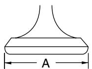 | 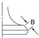 | 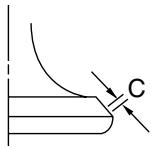 | 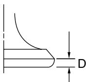 |
| Head Diameter | Face Width | Seat Width | Margin Thickness |
| “A” head diameter | IN | 26.9 ~ 27.1 mm(1.0591 ~ 1.0669 in) | ---- |
| EX | 27.9 ~ 28.1 mm(1.0984 ~ 1.1063 in) | ---- |
| “B” face width | IN | 2.26 mm (0.089 in) | ---- |
| EX | 2.26 mm (0.089 in) | ---- |
| “C” seat width | IN | 0.9 ~ 1.1 mm(0.0354 ~ 0.0433 in) | 1.6 mm(0.0630 in) |
| EX | 0.9 ~ 1.1 mm(0.0354 ~ 0.0433 in) | 1.6 mm(0.0630 in) |
| “D” margin thickness | IN | 1 mm (0.0394 in) | 0.85 mm(0.033 in) |
| EX | 1 mm (0.0394 in) | 0.85 mm(0.033 in) |
| Stem outside diameter | IN | 4.475 ~ 4.490 mm(0.1762 ~ 0.1768 in) | 4.445 mm(0.1750 in) |
| EX | 4.965 ~ 4.980 mm(0.1955 ~ 0.1961 in) | 4.935 mm(0.1943 in) |
| Guide inside diameter | IN | 4.500 ~ 4.512 mm(0.1772 ~ 0.1776 in) | 4.550 mm(0.1791 in) |
| EX | 5.000 ~ 5.012 mm(0.1969 ~ 0.1973 in) | 5.050 mm(0.1988 in) |
| Stem-to-guide clearance | IN | 0.010 ~ 0.037 mm(0.0004 ~ 0.0015 in) | 0.08 mm(0.003 in) |
| EX | 0.020 ~ 0.047 mm(0.0008 ~ 0.0019 in) | 0.10 mm(0.004 in) |
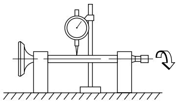
| Stem runout limit | | ---- | 0.01 mm(0.0004 in) |
 | | |
| Valve spring: | | | |
| Free length | IN | 39.46 mm (1.55 in) | 38.46 mm(1.51 in) |
| EX | 37.61 mm (1.48 in) | 36.61 mm(1.44 in) |
| Set length (valve closed) | IN | 27.87 mm (1.10 in) | ---- |
| EX | 28.38 mm (1.12 in) | ---- |
| Compressed force(installed) | IN | 130.2 ~ 149.8 N at 27.87 mm(13.28 ~ 15.28 kg at 27.87 mm,29.27 ~ 33.68 lb at 1.10 in) | ---- |
| EX | 123.1 ~ 141.7 N at 28.38 mm(12.55~ 14.45 kg at 28.38 mm,27.67 ~ 31.85 lb at 1.12 in) | ---- |
| Tilt limit * | IN | ---- | 2.5°/ 1.7 mm(2.5°/0.067 in) |
| EX | ---- | 2.5°/1.6 mm(2.5°/0.063 in) |
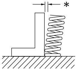 |
| Direction of winding (top view) | IN | Clockwise | ---- |
| EX | Clockwise | ---- |
| Piston: | | | |
| Piston to cylinder clearance | 0.040 ~ 0.065 mm(0.0016 ~ 0.0026 in) | 0.1 mm(0.004 in) |
| Piston size “D” | 94.945 ~ 94.960 mm(3.738 ~ 3.739 in) | ---- |
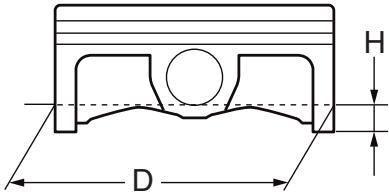 |
| Measuring point “H” | 8 mm (0.315 in) | ---- |
| Piston off-set | 1 mm (0.0394 in) | ---- |
| Piston pin bore inside diameter | 18.004 ~ 18.015 mm(0.7088 ~ 0.7093 in) | 18.045 mm(0.7104 in) |
| Piston pin outside diameter | 17.991 ~ 18.000 mm(0.7083 ~ 0.7087 in) | 17.971 mm(0.7075 in) |
Piston rings:Top ring: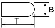 | | |
TypeDimensions (B × T)End gap (installed)Side clearance (installed)2nd ring: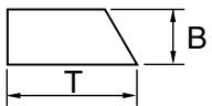 | Barrel1.2 × 3.5 mm (0.05 × 0.14 in)0.20 ~ 0.30 mm(0.008 ~ 0.012 in)0.030 ~ 0.065 mm(0.0012 ~ 0.0026 in) | --------0.55 mm(0.022 in)0.12 mm(0.005 in) |
TypeDimensions (B × T)End gap (installed)Side clearanceOil ring: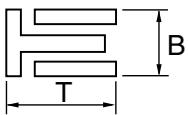 | Taper1.00 × 3.35 mm (0.04 × 0.13 in)0.35 ~ 0.50 mm(0.014 ~ 0.020 in)0.020 ~ 0.055 mm(0.0008 ~ 0.0022 in) | --------0.85 mm(0.033 in)0.12 mm(0.005 in) |
| Dimensions (B × T)End gap (installed) | 2.0 × 2.9 mm (0.08 × 0.11 in)0.2 ~ 0.5 mm (0.01 ~ 0.02 in) | ---- |
Crankshaft:Crank width “A”Runout limit “C”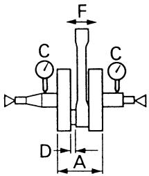 Big end side clearance “D”Small end free play “F” Big end side clearance “D”Small end free play “F” | 61.95 ~ 62.00 mm(2.439 ~ 2.441 in)0.03 mm (0.0012 in)0.15 ~ 0.45 mm(0.0059 ~ 0.0177 in)0.4 ~ 1.0 mm (0.02 ~ 0.04 in) | ----0.05 mm(0.002 in)0.50 mm(0.02 in)2.0 mm(0.08 in) |
| Balancer:Balancer drive method | Gear | ---- |
| Air filter oil grade: | Foam-air-filter oil or equivalent oil | ---- |
| Item | Standard | Limit |
| Clutch: | | |
| Friction plate thickness | 2.92 ~ 3.08 mm(0.115 ~ 0.121 in) | 2.8 mm(0.110 in) |
| Quantity | 8 | ---- |
| Clutch plate 1 thickness | 1.9 ~ 2.1 mm (0.075 ~ 0.083 in) | ---- |
| Quantity | 4 | ---- |
| Warp limit | ---- | 0.1 mm(0.004 in) |
| Clutch plate 2 thickness | 1.5 ~ 1.7 mm (0.059 ~ 0.067 in) | ---- |
| Quantity | 3 | ---- |
| Warp limit | ---- | 0.1 mm(0.004 in) |
| Clutch spring free length | 50.0 mm (1.97 in) | 49.0 mm(1.93 in) |
| Quantity | 6 | ---- |
| Clutch housing thrust clearance | 0.10 ~ 0.35 mm(0.0039 ~ 0.0138 in) | ---- |
| Clutch housing radial clearance | 0.010 ~ 0.044 mm(0.0004 ~ 0.0017 in) | ---- |
| Clutch release method | Inner push, cam push | ---- |
| Shifter: | | |
| Shifter type | Cam drum and guide bar | ---- |
| Guide bar bending limit | ---- | 0.05 mm(0.002 in) |
| Kickstarter: | | |
| Type | Ratchet type | ---- |
| Carburetor: | | |
| I. D. mark | 5TJE E0 | ---- |
| Main jet | (M.J) | #162 | ---- |
| Main air jet | (M.A.J) | ø2.0 | ---- |
| Jet needle | (J.N) | NFNT | ---- |
| Cutaway | (C.A) | 1.5 | ---- |
| Pilot jet | (P.J) | #45 | ---- |
| Pilot air jet | (P.A.J) | #70 | ---- |
| Pilot outlet | (P.O) | ø0.9 | ---- |
| Bypass | (B.P) | ø1.0 | ---- |
| Valve seat size | (V.S) | ø3.8 | ---- |
| Starter jet | (G.S) | #65 | ---- |
| Leak jet | (Acc.P) | #60 | ---- |
| Float height | (F.H) | 8 mm (0.31 in) | ---- |
| Engine idle speed | 1,750 ~ 1,850 r/min | ---- |
| Intake vacuum | 34.8 ~ 40.1 kPa(261 ~ 301 mmHg,10.28 ~ 11.85 inHg) | ---- |
| Hot starter lever free play | 3 ~ 6 mm (0.12 ~ 0.24 in) | ---- |
| Item | Standard | Limit |
| Lubrication system: | | |
| Oil filter type | Paper type | ---- |
| Oil pump type | Trochoid type | ---- |
| Tip clearance “A” | 0.12 mm or less(0.0047 in or less) | 0.20 mm(0.008 in) |
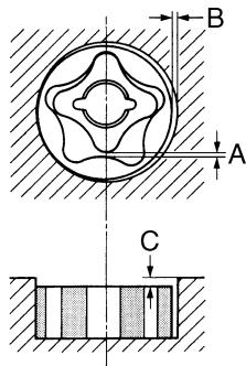 | | |
| Tip clearance “B” | 0.09 ~ 0.17 mm(0.0035 ~ 0.0067 in) | 0.24 mm(0.009 in) |
| Side clearance “C” | 0.03 ~ 0.10 mm(0.0012 ~ 0.0039 in) | 0.17 mm(0.007 in) |
| Bypass valve setting pressure | 40 ~ 80 kPa (0.4 ~ 0.8 kg/cm2,5.69 ~ 11.38 psi) | ---- |
| Cooling: | | |
| Radiator core size | | |
| Width | 120.2 mm (4.73 in) | ---- |
| Height (Left/Right) | 260 mm (10.24 in)/240 mm (9.45 in) | ---- |
| Thickness | 22 mm (0.87 in) | ---- |
| Radiator cap opening pressure | 110 kPa (1.1 kg/cm2, 15.6 psi) | ---- |
| Radiator capacity (total) | 0.57 L (0.50 Imp qt, 0.60 US qt) | ---- |
| Water pump | | |
| Type | Single-suction centrifugal pump | ---- |
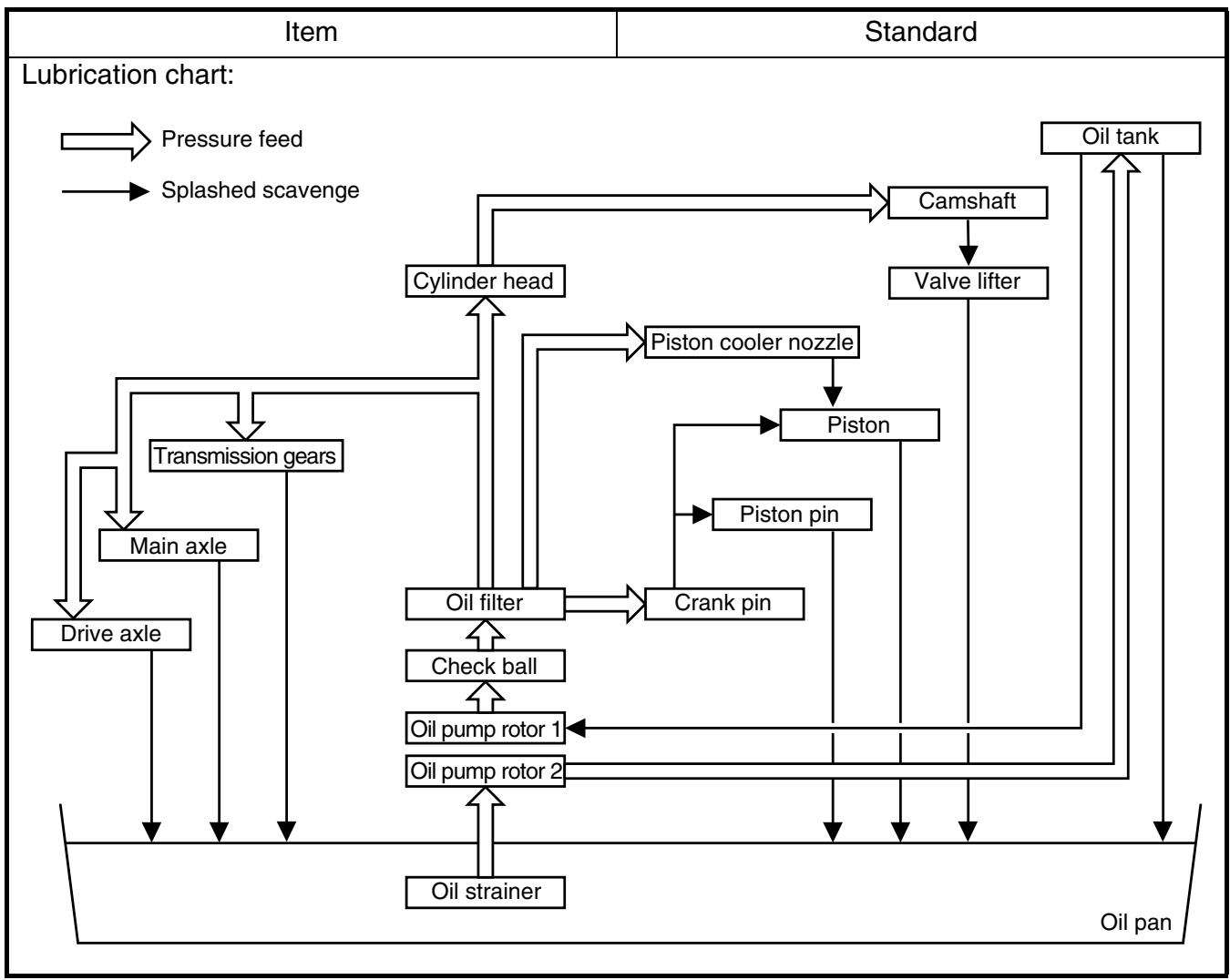
flowchart
graph TD
    A["Oil strainer"] --> B["Oil pump rotor 2"]
    B --> C["Oil pump rotor 1"]
    C --> D["Check ball"]
    D --> E["Oil filter"]
    E --> F["Cylinder head"]
    F --> G["Piston cooler nozzle"]
    G --> H["Piston"]
    H --> I["Crank pin"]
    I --> J["Piston pin"]
    J --> K["Piston"]
    K --> L["Valve lifter"]
    L --> M["Camshaft"]
    M --> N["Oil tank"]
    style A fill:#f9f,stroke:#333
    style N fill:#bbf,stroke:#333
| Part to be tightened | Thread size | Q'ty | Tightening torque |
| Nm | m·kg | ft·lb |
| Spark plug | M10S × 1.0 | 1 | 13 | 1.3 | 9.4 |
| Camshaft cap | M6 × 1.0 | 10 | 10 | 1.0 | 7.2 |
| Cylinder head blind plug screw | M12 × 1.0 | 1 | 28 | 2.8 | 20 |
| Cylinder head (stud bolt) | M8 × 1.25 | 1 | 15 | 1.5 | 11 |
| (bolt) | M10 × 1.25 | 4 | Refer to NOTE.*1 |
| (bolt) | M6 × 1.0 | 2 | 10 | 1.0 | 7.2 |
| Cylinder head cover | M6 × 1.0 | 2 | 10 | 1.0 | 7.2 |
| Cylinder | M6 × 1.0 | 1 | 10 | 1.0 | 7.2 |
| Timing chain tensioner | M6 × 1.0 | 2 | 10 | 1.0 | 7.2 |
| Tensioner cap bolt | M6 × 1.0 | 1 | 7 | 0.7 | 5.1 |
| Timing chain guide (rear) | M6 × 1.0 | 2 | 10 | 1.0 | 7.2 |
| Exhaust pipe (nut) | M8 × 1.25 | 1 | 20 | 2.0 | 14 |
| (bolt) | M8 × 1.25 | 1 | 20 | 2.0 | 14 |
| Silencer | M8 × 1.25 | 2 | 30 | 3.0 | 22 |
| Silencer clamp | M8 × 1.25 | 1 | 16 | 1.6 | 11 |
| Exhaust pipe protector | M6 × 1.0 | 3 | 10 | 1.0 | 7.2 |
| Spark arrester | M5 × 0.8 | 4 | 7 | 0.7 | 5.1 |
| Silencer cap | M5 × 0.8 | 6 | 5 | 0.5 | 3.6 |
| Air induction pipe | M6 × 1.0 | 2 | 10 | 1.0 | 7.2 |
| Air cut-off valve assembly and bracket | M6 × 1.0 | 2 | 10 | 1.0 | 7.2 |
| Bracket (air cut-off valve) and frame | M6 × 1.0 | 2 | 7 | 0.7 | 5.1 |
| Carburetor joint | M6 × 1.0 | 3 | 10 | 1.0 | 7.2 |
| Carburetor joint clamp | M4 × 0.7 | 1 | 3 | 0.3 | 2.2 |
| Air filter case | M6 × 1.0 | 2 | 8 | 0.8 | 5.8 |
| Air filter joint clamp | M6 × 1.0 | 1 | 3 | 0.3 | 2.2 |
| Air filter joint and air filter case | M5 × 0.8 | 1 | 4 | 0.4 | 2.9 |
| Throttle cable adjust bolt and locknut | M6 × 0.75 | 1 | 4 | 0.4 | 2.9 |
| Throttle cable (pull) | M6 × 1.0 | 1 | 4 | 0.4 | 2.9 |
| Throttle cable (return) | M12 × 1.0 | 1 | 11 | 1.1 | 8.0 |
| Throttle cable cover | M5 × 0.8 | 2 | 4 | 0.4 | 2.9 |
| Hot starter plunger | M12 × 1.0 | 1 | 2 | 0.2 | 1.4 |
| Hot starter cable adjust bolt and locknut | M6 × 0.75 | 1 | 4 | 0.4 | 2.9 |
| Air filter element | M6 × 1.0 | 1 | 2 | 0.2 | 1.4 |
| Radiator stay | M6 × 1.0 | 6 | 7 | 0.7 | 5.1 |
| Radiator | M6 × 1.0 | 4 | 10 | 1.0 | 7.2 |
| Radiator hose clamp | M6 × 1.0 | 8 | 2 | 0.2 | 1.4 |
| Radiator pipe 1, 2 | M10 × 1.0 | 2 | 10 | 1.0 | 7.2 |
| Impeller | M8 × 1.25 | 1 | 14 | 1.4 | 10 |
| Water pump housing cover | M6 × 1.0 | 3 | 10 | 1.0 | 7.2 |
| Coolant drain bolt | M6 × 1.0 | 1 | 10 | 1.0 | 7.2 |
| Oil pump cover | M4 × 0.7 | 1 | 2 | 0.2 | 1.4 |
| Oil pump | M6 × 1.0 | 2 | 10 | 1.0 | 7.2 |
| Oil pump drive gear shaft | M6 × 1.0 | 1 | 10 | 1.0 | 7.2 |

| Part to be tightened | Thread size | Q'ty | Tightening torque |
| Nm | m·kg | ft·lb |
| Engine oil drain bolt (oil filter) | M6 × 1.0 | 1 | 10 | 1.0 | 7.2 |
| Oil filter cover | M6 × 1.0 | 2 | 10 | 1.0 | 7.2 |
| Oil check bolt (cylinder head) | M6 × 1.0 | 1 | 10 | 1.0 | 7.2 |
| Oil hose clamp | — | 2 | 2 | 0.2 | 1.4 |
| Clutch cover | M6 × 1.0 | 7 | 10 | 1.0 | 7.2 |
| Crankcase cover (right) | M6 × 1.0 | 8 | 10 | 1.0 | 7.2 |
| M6 × 1.0 | 2 | 12 | 1.2 | 8.7 |
| Crankcase cover (left) | M6 × 1.0 | 8 | 10 | 1.0 | 7.2 |
| Idle gear cover (starter motor) | M6 × 1.0 | 2 | 10 | 1.0 | 7.2 |
| Crankcase | M6 × 1.0 | 12 | 12 | 1.2 | 8.7 |
| Clutch cable holder | M6 × 1.0 | 1 | 10 | 1.0 | 7.2 |
| Oil drain bolt (crankcase right) | M10 × 1.25 | 1 | 20 | 2.0 | 14 |
| (crankcase left) | M6 × 1.0 | 1 | 20 | 2.0 | 14 |
| Oil check bolt (crankcase) | M6 × 1.0 | 1 | 10 | 1.0 | 7.2 |
| Oil strainer | M6 × 1.0 | 1 | 10 | 1.0 | 7.2 |
| Crankcase bearing stopper | M6 × 1.0 | 4 | 14 | 1.4 | 10 |
| Crankcase bearing stopper | M6 × 1.0 | 8 | 10 | 1.0 | 7.2 |
| Drive axle oil seal stopper | M6 × 1.0 | 2 | 10 | 1.0 | 7.2 |
| Ratchet wheel guide | M6 × 1.0 | 2 | 12 | 1.2 | 8.7 |
| Kickstarter | M8 × 1.25 | 1 | 33 | 3.3 | 24 |
| Screw (kickstarter) | M6 × 1.0 | 1 | 7 | 0.7 | 5.1 |
| Starter clutch | M6 × 1.0 | 6 | 16 | 1.6 | 11 |
| Primary drive gear | M20 × 1.0 | 1 | 110 | 11.0 | 80 |
| Clutch boss | M20 × 1.0 | 1 | 75 | 7.5 | 54 |
| Clutch cable adjust bolt and locknut | M8 × 1.0 | 1 | 4 | 0.4 | 2.9 |
| Clutch spring | M6 × 1.0 | 6 | 10 | 1.0 | 7.2 |
| Balancer | M10 × 1.0 | 1 | 45 | 4.5 | 32 |
| Balancer driven gear | M14 × 1.0 | 1 | 50 | 5.0 | 36 |
| Balancer weight plate | M6 × 1.0 | 3 | 10 | 1.0 | 7.2 |
| Drive sprocket | M20 × 1.0 | 1 | 75 | 7.5 | 54 |
| Drive sprocket cover | M6 × 1.0 | 2 | 8 | 0.8 | 5.8 |
| Shift pedal | M6 × 1.0 | 1 | 12 | 1.2 | 8.7 |
| Shift guide | M6 × 1.0 | 2 | 10 | 1.0 | 7.2 |
| Stopper lever | M6 × 1.0 | 1 | 10 | 1.0 | 7.2 |
| Segment | M8 × 1.25 | 1 | 30 | 3.0 | 22 |
NOTE:
△ - marked portion shall be checked for torque tightening after break-in or before each race.
NOTE:
*1: Tighten the cylinder head bolts to 30 Nm (3.0 m • kg, 22 ft • lb) in the proper tightening sequence, remove and retighten the cylinder head bolts to 20 Nm (2.0 m • kg, 14 ft • lb) in the proper tightening sequence, and then tighten the cylinder head bolts further to reach the specified angle 180° in the proper tightening sequence.
EC212201
CHASSIS
| Item | Standard | Limit |
| Steering system:Steering bearing type | Taper roller bearing | ---- |
| Front suspension: | USA, CDN | EUROPE | AUS, NZ, ZA |
| Front fork travel | 300 mm (11.8 in) | ← | ← |
| Fork spring free length | 460 mm (18.1 in) | ← | ← |
| Spring rate, STD | K = 4.5 N/mm(0.459 kg/mm,25.7 lb/in) | ← | ← |
| Optional spring/spacer | Yes | ← | ← |
| Oil capacity | 648 cm ^3 (22.8 Imp oz,21.9 US oz) | 655 cm ^3 (23.1 Imp oz,22.1 US oz) | ← |
| Oil level | 132 mm (5.20 in) | 125 mm (4.92 in) | ← |
| <Min.~Max.>(From top of outer tube with inner tube and damper rod fully compressed without spring.) | 95 ~ 150 mm(3.74 ~ 5.91 in) | ← | ← |
| Oil grade | Suspension oil“S1” | ← | ← |
| Inner tube outer diameter | 48 mm (1.89 in) | ← | ← |
| Front fork top end | Zero mm (Zero in) | ← | ← |
| Rear suspension: | USA, CDN | EUROPE | AUS, NZ, ZA |
| Shock absorber travel | 130 mm (5.12 in) | ← | ← |
| Spring free length | 260 mm (10.24 in) | ← | ← |
| Fitting length | 252.5 mm (9.94 in) | 251.5 mm (9.90 in) | 252.5 mm (9.94 in) |
| <Min.~Max.> | 238.5 ~ 258.5 mm(9.39 ~ 10.18 in) | ← | ← |
| Spring rate, STD | K = 54.0 N/mm(5.50 kg/mm,308.0 lb/in) | ← | ← |
| Optional spring | Yes | ← | ← |
| Enclosed gas pressure | 1,000 kPa(10 kg/cm ^2 , 142 psi) | ← | ← |
| Swingarm:Swingarm free play limitEnd | ---- | 1.0 mm(0.04 in) |
| Item | Standard | Limit |
| Wheel: | | |
| Front wheel type | Spoke wheel | ---- |
| Rear wheel type | Spoke wheel | ---- |
| Front rim size/material | 21 × 1.60/Aluminum | ---- |
| Rear rim size/material | 18 × 2.15/Aluminum | ---- |
| Rim runout limit: | | |
| Radial | ---- | 2.0 mm(0.08 in) |
| Lateral | ---- | 2.0 mm(0.08 in) |
| Drive chain: | | |
| Type/manufacturer | DID520VM/DAIDO | ---- |
| Number of links | 113 links + joint | ---- |
| Chain slack | 48 ~ 58 mm (1.9 ~ 2.3 in) | ---- |
| Chain length (15 links) | ---- | 239.3 mm(9.42 in) |
| Front disc brake: | | |
| Disc outside dia. × Thickness | 250 × 3.0 mm (9.84 × 0.12 in) | 250 × 2.5 mm(9.84 × 0.10 in) |
| Pad thickness | 4.4 mm (0.17 in) | 1.0 mm(0.04 in) |
| Master cylinder inside dia. | 11.0 mm (0.433 in) | ---- |
| Caliper cylinder inside dia. | 27.0 mm (1.063 in) × 2 | ---- |
| Brake fluid type | DOT #4 | ---- |
| Rear disc brake: | | |
| Disc outside dia. × Thickness | 245 × 4.0 mm (9.65 × 0.16 in) | 245 × 3.5 mm(9.65 × 0.14 in) |
| Deflection limit | ---- | 0.15 mm(0.006 in) |
| Pad thickness | 6.4 mm (0.25 in) | 1.0 mm(0.04 in) |
| Master cylinder inside dia. | 11.0 mm (0.433 in) | ---- |
| Caliper cylinder inside dia. | 25.4 mm (1.000 in) × 1 | ---- |
| Brake fluid type | DOT #4 | ---- |
| Brake lever and brake pedal: | | |
| Brake lever position | 95 mm (3.74 in) | ---- |
| Brake pedal height(vertical height above footrest top) | 10 mm (0.39 in) | ---- |
| Clutch lever free play (lever end) | 8 ~ 13 mm (0.31 ~ 0.51 in) | ---- |
| Throttle grip free play | 3 ~ 5 mm (0.12 ~ 0.20 in) | ---- |
| Part to be tightened | Thread size | Q'ty | Tightening torque |
| Nm | m·kg | ft·lb |
| Handle crown and outer tube | M8 × 1.25 | 4 | 21 | 2.1 | 15 |
| Under bracket and outer tube | M8 × 1.25 | 4 | 21 | 2.1 | 15 |
| Handle crown and steering shaft | M24 × 1.0 | 1 | 145 | 14.5 | 105 |
| Handlebar holder (upper) | M8 × 1.25 | 4 | 28 | 2.8 | 20 |
| Handlebar holder (lower) | M12 × 1.25 | 2 | 34 | 3.4 | 24 |
| Steering ring nut | M28 × 1.0 | 1 | Refer to NOTE. |
| Front fork and cap bolt | M51 × 1.5 | 2 | 30 | 3.0 | 22 |
| Front fork and base valve | M30 × 1.0 | 2 | 55 | 5.5 | 40 |
| Cap bolt and damper rod (front fork) | M12 × 1.25 | 2 | 29 | 2.9 | 21 |
| Bleed screw (front fork) and cap bolt | M5 × 0.8 | 2 | 1 | 0.1 | 0.7 |
| Front fork and protector | M6 × 1.0 | 6 | 7 | 0.7 | 5.1 |
| Front fork protector and brake hose holder | M6 × 1.0 | 2 | 7 | 0.7 | 5.1 |
| Throttle cable cap | M5 × 0.8 | 2 | 4 | 0.4 | 2.9 |
| Clutch lever holder mounting | M5 × 0.8 | 2 | 4 | 0.4 | 2.9 |
| Clutch lever mounting | M6 × 1.0 | 1 | 4 | 0.4 | 2.9 |
| Hot starter lever holder mounting | M5 × 0.8 | 2 | 4 | 0.4 | 2.9 |
| Hot starter lever mounting | M5 × 0.8 | 1 | 2 | 0.2 | 1.4 |
| Front brake master cylinder and bracket | M6 × 1.0 | 2 | 9 | 0.9 | 6.5 |
| Front brake master cylinder cap | M4 × 0.7 | 2 | 2 | 0.2 | 1.4 |
| Brake lever mounting (bolt) | M6 × 1.0 | 1 | 6 | 0.6 | 4.3 |
| Brake lever mounting (nut) | M6 × 1.0 | 1 | 6 | 0.6 | 4.3 |
| Brake lever position locknut | M6 × 1.0 | 1 | 5 | 0.5 | 3.6 |
| Hose guide (front brake hose) and hose guide bracket | M5 × 0.8 | 1 | 4 | 0.4 | 2.9 |
| Hose guide (front brake hose) and under bracket | M6 × 1.0 | 1 | 4 | 0.4 | 2.9 |
| Front brake hose union bolt (master cylinder) | M10 × 1.25 | 1 | 30 | 3.0 | 22 |
| Front brake hose union bolt (caliper) | M10 × 1.25 | 1 | 30 | 3.0 | 22 |
| Front brake caliper and front fork | M8 × 1.25 | 2 | 23 | 2.3 | 17 |
| Front brake caliper and brake hose holder | M6 × 1.0 | 1 | 10 | 1.0 | 7.2 |
| Brake caliper (front and rear) and pad pin plug | M10 × 1.0 | 2 | 3 | 0.3 | 2.2 |
| Brake caliper (front and rear) and pad pin | M10 × 1.0 | 2 | 18 | 1.8 | 13 |
| Brake caliper (front and rear) and bleed screw | M8 × 1.25 | 2 | 6 | 0.6 | 4.3 |
| Front wheel axle and nut | M16 × 1.5 | 1 | 90 | 9.0 | 65 |
| Front wheel axle holder | M8 × 1.25 | 4 | 21 | 2.1 | 15 |
| Front brake disc and wheel hub | M6 × 1.0 | 6 | 12 | 1.2 | 8.7 |
| Rear brake disc and wheel hub | M6 × 1.0 | 6 | 14 | 1.4 | 10 |
| Brake pedal mounting | M8 × 1.25 | 1 | 26 | 2.6 | 19 |
| Rear brake master cylinder and frame | M6 × 1.0 | 2 | 10 | 1.0 | 7.2 |
| Rear brake master cylinder cap | M4 × 0.7 | 2 | 2 | 0.2 | 1.4 |
| Rear brake hose union bolt (caliper) | M10 × 1.25 | 1 | 30 | 3.0 | 22 |
| Rear brake hose union bolt (master cylinder) | M10 × 1.25 | 1 | 30 | 3.0 | 22 |
NOTE:
1. First, tighten the ring nut approximately 38 Nm (3.8 m • kg, 27 ft • lb) by using the ring nut wrench, then loosen the ring nut one turn.
2. Retighten the ring nut 7 Nm (0.7 m • kg, 5.1 ft • lb).
| Part to be tightened | Thread size | Q'ty | Tightening torque |
| Nm | m·kg | ft·lb |
| Rear wheel axle and nut | M20 × 1.5 | 1 | 125 | 12.5 | 90 |
| Driven sprocket and wheel hub | M8 × 1.25 | 6 | 50 | 5.0 | 36 |
| Nipple (spoke) | — | 72 | 3 | 0.3 | 2.2 |
| Disc cover and rear brake caliper | M6 × 1.0 | 2 | 10 | 1.0 | 7.2 |
| Protector and rear brake caliper | M6 × 1.0 | 2 | 7 | 0.7 | 5.1 |
| Chain puller adjust bolt and locknut | M8 × 1.25 | 2 | 19 | 1.9 | 13 |
| Engine mounting: | | | | | |
| Engine upper bracket and frame | M10 × 1.25 | 4 | 55 | 5.5 | 40 |
| Engine lower bracket and frame | M8 × 1.25 | 4 | 34 | 3.4 | 24 |
| Engine and engine bracket (lower) | M10 × 1.25 | 1 | 53 | 5.3 | 38 |
| Engine and engine bracket (upper) | M10 × 1.25 | 1 | 55 | 5.5 | 40 |
| Engine and frame (lower) | M10 × 1.25 | 1 | 53 | 5.3 | 38 |
| Engine guard | M6 × 1.0 | 3 | 7 | 0.7 | 5.1 |
| Regulator mounting | M6 × 1.0 | 2 | 7 | 0.7 | 5.1 |
| Pivot shaft and nut | M16 × 1.5 | 1 | 85 | 8.5 | 61 |
| Relay arm and swingarm | M14 × 1.5 | 1 | 70 | 7.0 | 50 |
| Relay arm and connecting rod | M14 × 1.5 | 1 | 80 | 8.0 | 58 |
| Connecting rod and frame | M14 × 1.5 | 1 | 80 | 8.0 | 58 |
| Rear shock absorber and frame | M10 × 1.25 | 1 | 56 | 5.6 | 40 |
| Rear shock absorber and relay arm | M10 × 1.25 | 1 | 53 | 5.3 | 38 |
| Rear frame and frame (upper) | M8 × 1.25 | 1 | 38 | 3.8 | 27 |
| Rear frame and frame (lower) | M8 × 1.25 | 2 | 32 | 3.2 | 23 |
| Swingarm and brake hose holder | M5 × 0.8 | 4 | 2 | 0.2 | 1.4 |
| Swingarm and patch | M4 × 0.7 | 4 | 2 | 0.2 | 1.4 |
| Drive chain tensioner mounting (upper) | M8 × 1.25 | 1 | 16 | 1.6 | 11 |
| Drive chain tensioner mounting (lower) | M8 × 1.25 | 1 | 16 | 1.6 | 11 |
| Chain support and swingarm | M6 × 1.0 | 3 | 7 | 0.7 | 5.1 |
| Seal guard and swingarm | M5 × 0.8 | 4 | 6 | 0.6 | 4.3 |
| Fuel tank mounting | M6 × 1.0 | 2 | 9 | 0.9 | 6.5 |
| Fuel tank and fuel cock | M6 × 1.0 | 2 | 4 | 0.4 | 2.9 |
| Fuel tank and seat set bracket | M6 × 1.0 | 1 | 7 | 0.7 | 5.1 |
| Fuel tank and fuel tank bracket | M6 × 1.0 | 4 | 7 | 0.7 | 5.1 |
| Seat mounting | M8 × 1.25 | 2 | 23 | 2.3 | 17 |
| Side cover mounting | M6 × 1.0 | 2 | 7 | 0.7 | 5.1 |
| Air scoop and fuel tank | M6 × 1.0 | 6 | 7 | 0.7 | 5.1 |
| Air scoop and radiator panel (lower) | M6 × 1.0 | 2 | 6 | 0.6 | 4.3 |
| Front fender mounting | M6 × 1.0 | 4 | 7 | 0.7 | 5.1 |
| Rear fender mounting (front) | M6 × 1.0 | 2 | 7 | 0.7 | 5.1 |
| Rear fender mounting (rear) | M6 × 1.0 | 2 | 11 | 1.1 | 8.0 |
| Multi-function display bracket mounting | M6 × 1.0 | 2 | 7 | 0.7 | 5.1 |
| Multi-function display mounting | M5 × 0.8 | 2 | 4 | 0.4 | 2.9 |
| Plate 1 and protector | M5 × 0.8 | 2 | 4 | 0.4 | 2.9 |
| Plate 2 and protector | — | 2 | 0.5 | 0.05 | 0.36 |
| Speed sensor lead holder and under bracket | M6 × 1.0 | 1 | 13 | 1.3 | 9.4 |
| Headlight body and headlight unit | — | 2 | 1 | 0.1 | 0.7 |
| Headlight mounting (left and right) | M6 × 1.0 | 2 | 7 | 0.7 | 5.1 |
| Taillight mounting | — | 3 | 1 | 0.1 | 0.7 |
| Taillight lead clamp and rear fender | — | 3 | 0.5 | 0.05 | 0.36 |
| Catch tank (upper) | M6 × 1.0 | 1 | 16 | 1.6 | 11 |
| Catch tank (lower) | M6 × 1.0 | 1 | 7 | 0.7 | 5.1 |
| Footrest bracket and frame | M10 × 1.25 | 4 | 55 | 5.5 | 40 |
| Sidestand mounting | M10 × 1.25 | 1 | 25 | 2.5 | 18 |
NOTE:
△- marked portion shall be checked for torque tightening after break-in or before each race.
EC212300
ELECTRICAL
| Item | Standard | Limit |
| Ignition system: | | |
| Advancer type | Electrical | ---- |
| C.D.I.: | | |
| Pickup coil resistance (color) | 248 ~ 372 Ω at 20 °C (68 °F)(White – Red) | ---- |
| CDI unit-model/manufacturer | 5TJ-E0/YAMAHA (For USA)5TJ-F0/YAMAHA(Except for USA) | ---- |
| Ignition coil: | | |
| Model/manufacturer | 5TA-10/DENSO | ---- |
| Minimum spark gap | 6 mm (0.24 in) | ---- |
| Primary winding resistance | 0.08 ~ 0.10 Ω at 20 °C (68 °F) | ---- |
| Secondary winding resistance | 4.6 ~ 6.8 kΩ at 20 °C (68 °F) | ---- |
| Charging system: | | |
| System type | AC magneto | ---- |
| Model (stator)/manufacturer | 5TJ 40/YAMAHA | ---- |
| Normal output | 14 V/120 W at 5,000 r/min | ---- |
| Charging coil resistance (color) | 0.288 ~ 0.432 Ω at 20 °C (68 °F)(White – Ground) | ---- |
| Lighting coil resistance (color) | 0.224 ~ 0.336 Ω at 20 °C (68 °F)(Yellow – Ground) | ---- |
| Rectifier/regulator: | | |
| Regulator type | Semiconductor short circuit | ---- |
| Model/manufacture | SH770AA/SHINDENGEN | ---- |
| Regulated voltage (AC) | 12.5 ~ 13.5 V | ---- |
| Regulated voltage (DC) | 14.0 ~ 15.0 V | ---- |
| Rectifier capacity (AC) | 12 A | ---- |
| Rectifier capacity (DC) | 8 A | ---- |
| Electric starting system: | | |
| Type | Constant mesh | ---- |
| Starter motor: | | |
| Model/manufacturer | 5UM20/YAMAHA | ---- |
| Operation voltage | 12 V | ---- |
| Output | 0.48 kW | ---- |
| Armature coil resistance | 0.0117 ~ 0.0143 Ω at 20 °C(68 °F) | ---- |
| Brush overall length | 7 mm (0.28 in) | 3.5 mm(0.14 in) |
| Brash quantity | 2 pcs. | ---- |
| Spring force | 3.92 ~ 5.88 N(400 ~ 600 g, 14.1 ~ 21.2 oz) | ---- |
| Commutator diameter | 17.6 mm (0.69 in) | 16.6 mm(0.65 in) |
| Mica undercut (depth) | 1.5 mm (0.06 in) | ---- |
MAINTENANCE SPECIFICATIONS
SPEC

| Item | Standard | Limit |
| Starter relay: | | |
| Model/manufacturer | 2768090-A/JIDECO | ---- |
| Amperage rating | 180 A | ---- |
| Coil winding resistance | 4.2 ~ 4.6 Ω at 20 °C (68 °F) | ---- |
| Starting circuit cut-off relay: | | |
| Model/manufacturer | ACM33221 M06/MATSUSHITA | ---- |
| Coil winding resistance | 75.69 ~ 92.51 Ω at 20 °C (68 °F) | ---- |
| Fuse (amperage × quantity): | | |
| Main fuse | 10 A × 1 | ---- |
| Reserve fuse | 10 A × 1 | ---- |
| Part to be tightened | Thread size | Q'ty | Tightening torque |
| Nm | m·kg | ft·lb |
| Stator | M5 × 0.8 | 2 | 7 | 0.7 | 5.1 |
| Holder (AC magneto lead) | M5 × 0.8 | 2 | 10 | 1.0 | 7.2 |
| Rotor | M12 × 1.25 | 1 | Refer to NOTE. |
| Neutral switch | M5 × 0.8 | 2 | 4 | 0.4 | 2.9 |
| Starter motor | M6 × 1.0 | 2 | 10 | 1.0 | 7.2 |
| Starter relay terminal | M6 × 1.0 | 2 | 4 | 0.4 | 2.9 |
| Pick-up coil | M6 × 1.0 | 2 | 10 | 1.0 | 7.2 |
NOTE:
Tighten the rotor nut to 65 Nm (6.5 m • kg, 47 ft • lb), loosen and retighten the rotor nut to 65 Nm (6.5 m • kg, 47 ft • lb).
GENERAL TORQUE SPECIFICATIONS/DEFINITION OF UNITS
EC220001
GENERAL TORQUE SPECIFICATIONS
This chart specifies torque for standard fasteners with standard I.S.O. pitch threads. Torque specifications for special components or assemblies are included in the applicable sections of this book. To avoid warpage, tighten multi-fastener assemblies in a crisscross fashion, in progressive stages, until full torque is reached. Unless otherwise specified, torque specifications call for clean, dry threads. Components should be at room temperature.
| A(Nut) | B(Bolt) | TORQUE SPECIFICATION |
| Nm | m•kg | ft•lb |
| 10 mm | 6 mm | 6 | 0.6 | 4.3 |
| 12 mm | 8 mm | 15 | 1.5 | 11 |
| 14 mm | 10 mm | 30 | 3.0 | 22 |
| 17 mm | 12 mm | 55 | 5.5 | 40 |
| 19 mm | 14 mm | 85 | 8.5 | 61 |
| 22 mm | 16 mm | 130 | 13 | 94 |
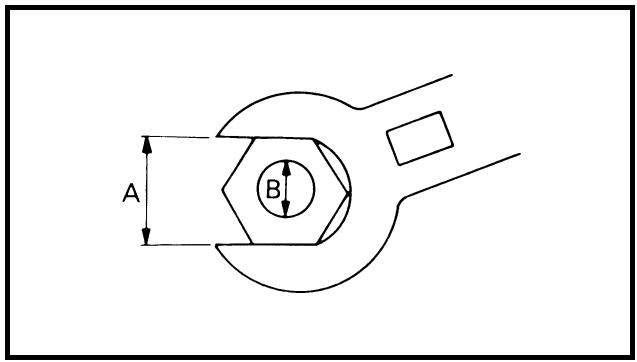
A: Distance between flats
B: Outside thread diameter
EC230000
DEFINITION OF UNITS
| Unit | Read | Definition | Measure |
| mmcm | millimetercentimeter | 10^-3 meter 10^-2 meter | LengthLength |
| kg | kilogram | 10^3 gram | Weight |
| N | Newton | 1kg × m/sec^2 | Force |
| Nm m • kg | Newton meterMeter kilogram | N × m m × kg | TorqueTorque |
| Pa | Pascal | N/m^2 | Pressure |
| N/mm | Newton per millimeter | N/mm | Spring rate |
| L cm^3 | LiterCubic centimeter | —— | Volume or capacityVolume or capacity |
| r/min | Revolution per minute | — | Engine speed |
CARACTERISTIQUES
CARACTERISTIQUES GENERALES
LUBRICATION DIAGRAMS
① Oil filter element
② Oil pump
③ Drive axle
④ Main axle
⑤ Crankshaft
⑥ Connecting rod
A From cylinder
B To oil tank
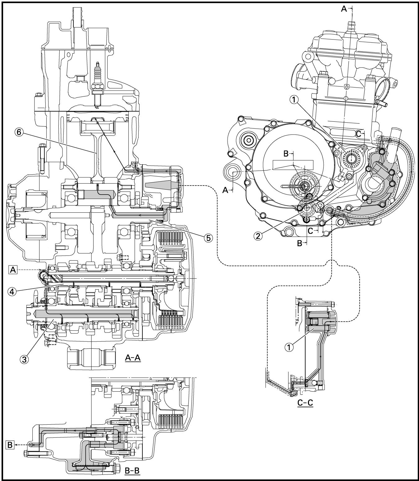
DIAGRAMMES DE LUBRIFICATION
① Intake camshaft
② Exhaust camshaft
A To main axle
B From oil pump
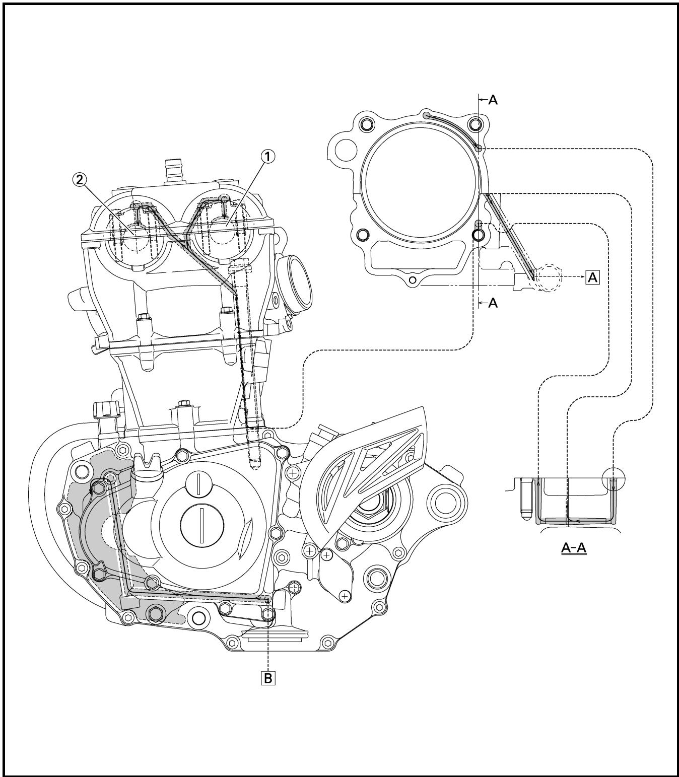
DIAGRAMMES DE LUBRIFICATION SCHMIERSYSTEM-SCHAUBILDER DIAGRAMAS DE ENGRASE
SPEC

① Fuel tank breather hose
② Clamp
③ Diode
④ Hot starter cable
⑤ Throttle position sensor lead
⑥ Wire harness
⑦ Hump (frame)
⑧ Negative battery lead
⑨ Starter motor lead
⑩ Neutral switch lead
⑪ AC magneto lead
⑫ Brake hose
⑬ Rectifier/regulator lead
⑭ Carburetor breather hose
⑮ Carburetor overflow hose
⑯ Catch tank breather hose

DIAGRAMME DE CHEMINEMENT DES CABLES
A Insert the end of the fuel tank breather hose into the hole in the steering stem.
B Fasten the throttle cable, hot starter cable and rectifier/regulator lead onto the frame. Locate the clamp end facing the lower side of the hot starter cable and cut off the tie end.
C Fasten the diode (at the marking), throttle cable and hot starter cable onto the frame. Locate the clamp end facing toward the lower right of the frame and with the tie end facing downward.
D Fasten the wire harness, throttle position sensor lead and clutch cable onto the frame. Pass the clamp through the hole in the stay (air cut-off valve). Locate the clamp end facing toward the lower side of the frame and cut off the tie end.
E Fasten the throttle position sensor lead onto the frame. Locate the clamp end facing toward the lower side of the frame and cut off the tie end.
F Pass the carburetor breather hoses, carburetor overflow hose and catch tank breather hose between the connecting rod and cross tube (frame).
G Pass the neutral switch lead on the inside of the engine bracket.
H Fasten the neutral switch lead and AC magneto lead onto the frame. Locate the clamp end facing toward the outside of the frame and tie end facing toward the rear of the frame.
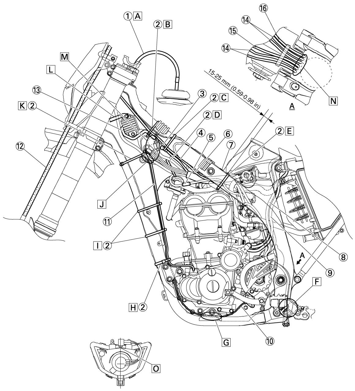
Fasten the AC magneto lead and neutral switch lead onto the frame. Locate the clamp end facing toward the rear of the frame and cut off the tie end.
☐ Pass the neutral switch lead and AC magneto lead on the inside of the wire harness.
K Fasten the AC magneto lead and neutral switch lead onto the frame.
L Pass the wire harness through the cable guide.
M Locate the couplers in the frame recess.
N Pass the carburetor breather hoses, carburetor overflow hose and catch tank breather hose so that the hoses do not contact the rear shock absorber.
☐ Secure the coupler by pushing it into the hole in
the headlight unit.

DIAGRAMME DE CHEMINEMENT DES CABLES KABELFÜHRUNGS-SCHAUBILD DIAGRAMA DE CABLEADO
SPEC

① Throttle cable (pull)
② Throttle cable (return)
③ Catch tank hose
④ Ignition coil
⑤ Clamp
⑥ Air induction hose (air cut-off valve - rear of cylinder head)
⑦ Catch tank breather hose
A Cross the pull and push throttle cables.
B Fasten the catch tank hose and air induction hose (air cut-off valve - rear of cylinder head) onto the frame. Locate the clamp end facing toward the lower side of the frame and cut off the tie end.
C Fasten the catch tank breather hose and carburetor breather hoses together.
D Pass the carburetor breather hose (of the throttle cable cover) through the hose holder.
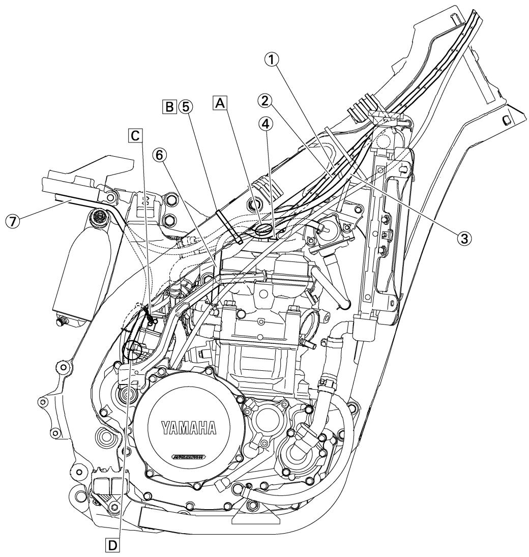
DIAGRAMME DE CHEMINEMENT DES CABLES KABELFÜHRUNGS-SCHAUBILD DIAGRAMA DE CABLEADO
SPEC

① Brake master cylinder
② Brake hose holder
③ Brake hose
A Install the brake hose so that its pipe portion directs as shown and lightly touches the projection on the brake caliper.
B Pass the brake hose into the brake hose holders.
C If the brake hose contacts the spring (rear shock absorber), correct its twist.
☐ Install the brake hose so that its pipe portion directs as shown and lightly touches the projection on the brake master cylinder.
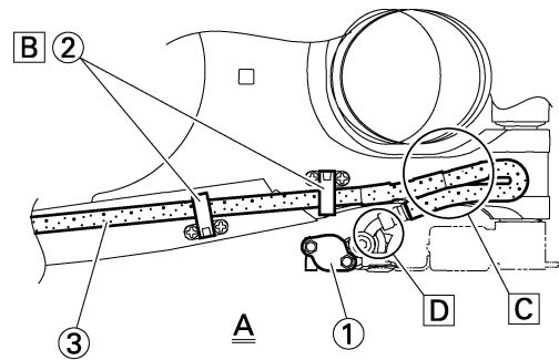
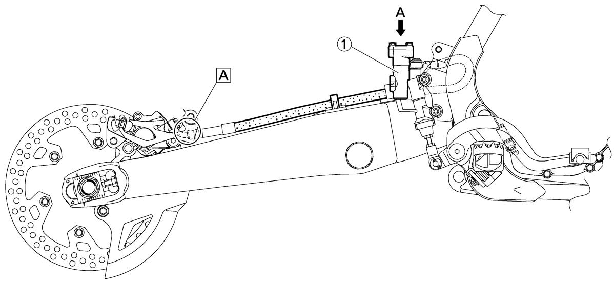
DIAGRAMME DE CHEMINEMENT DES CABLES KABELFÜHRUNGS-SCHAUBILD DIAGRAMA DE CABLEADO
SPEC

① Clamp
② Positive battery lead
③ Battery
④ Negative battery lead
⑤ Taillight coupler
⑥ CDI unit coupler (6-pin)
⑦ CDI unit coupler (3-pin)
⑧ CDI unit coupler (6-pin)
A Fasten the wire harness to the upper engine bracket (left side). Locate the clamp end facing toward the upper side of the frame with the tie end cut off on the inside of the frame.
B Fasten the wire harness to the upper engine bracket (left side). Locate the clamp end facing toward the upper side of the frame with the tie end cut off on the inside of the frame. Clamp the wire harness at the marking.
☐ Pass the starter motor lead through the hole in the relay holder.
D Fit the cover securely.
E Connect the wire harness to the starter relay.
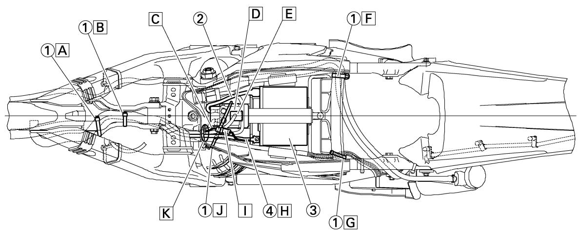
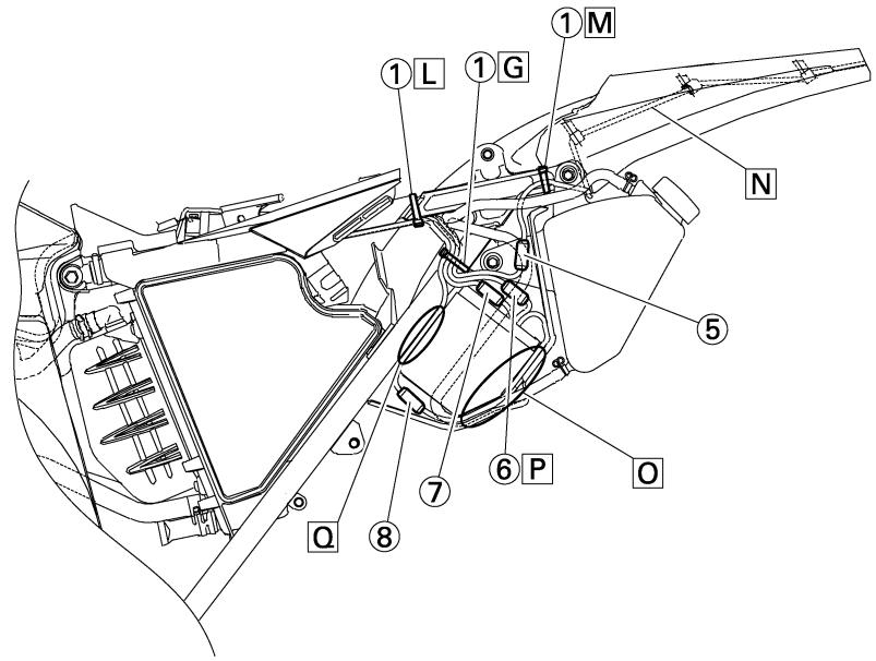
DIAGRAMME DE CHEMINEMENT DES CABLES KABELFÜHRUNGS-SCHAUBILD DIAGRAMA DE CABLEADO
SPEC

F Fasten the catch tank breather hose and catch tank hose to the rear frame. Clamp them close to where they are joined to the frame. Fasten the pipe tightly enough not to crush it. Locate the clamp end facing toward the rear of the frame with the tie end facing downward.
G Fasten the (three) CDI unit leads and taillight lead to the rear frame. Locate the clamp end facing toward the upper side of the frame and cut off the tie end.
H Connect the negative battery lead to the battery negative terminal.
☐ Connect the negative battery lead to the wire harness.
☐ Fasten the wire harness to the rear frame. Locate the clamp end facing toward the upper side of the frame and the tie end toward the inside of the frame. Clamp the wire harness at the marking.
K Pass the wire harness, starter relay lead, starting circuit cut-off relay lead and negative battery lead through the hole in the relay holder.
Fasten the (three) CDI unit leads and taillight lead to the rear frame. Locate the clamp end facing toward the lower side of the frame and cut off the tie end.
M Fasten the taillight lead to the rear frame. Locate the clamp end facing toward the upper side of the frame and cut off the tie end.
N Do not allow the taillight lead to slacken.
☐ Locate the CDI unit lead between the CDI unit and rear fender.
P Locate the CDI unit coupler in the clearance between the upper side of the CDI unit and lower side of the catch tank stay.
☐ Locate the CDI unit lead between the CDI unit and rear frame.
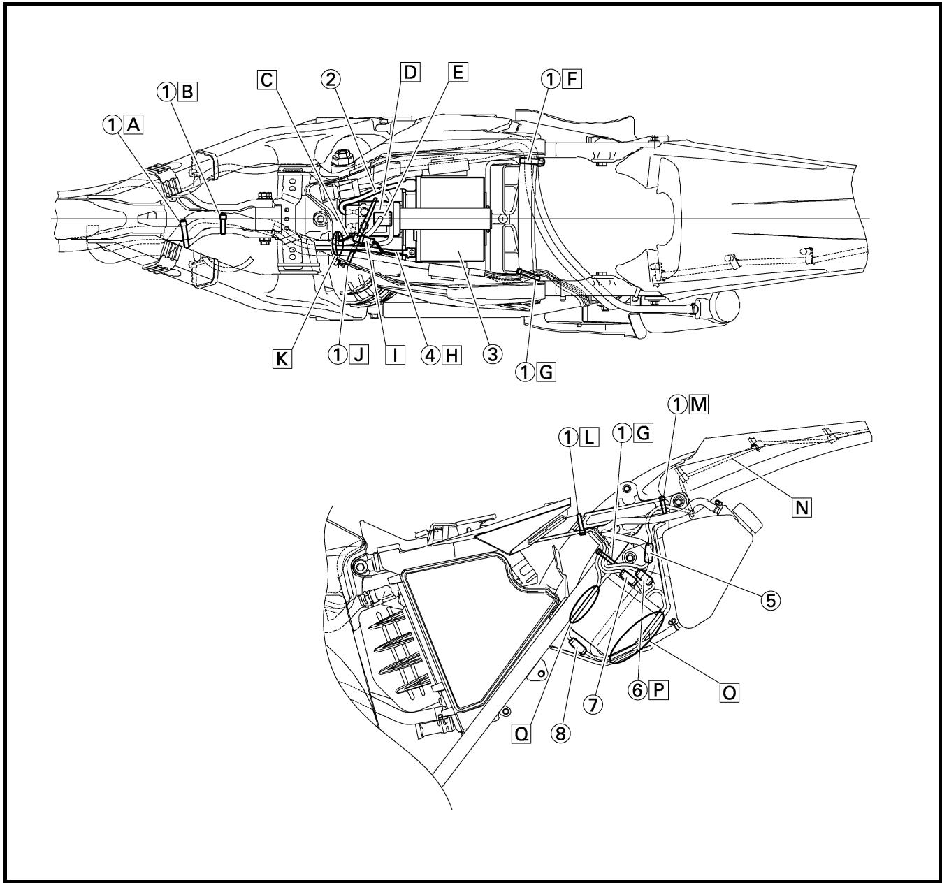
① Throttle cable
② Clamp
③ Brake hose
④ Clutch cable
⑤ Hose guide
⑥ Main switch coupler
⑦ Wire harness
⑧ Headlight coupler
⑨ Hot starter cable
⑩ Multi-function display bracket
⑪ Main switch
⑫ Upper bracket
⑬ Clutch switch coupler
⑭ Engine stop switch coupler
⑮ Multi-function display coupler
⑯ Start switch coupler
⑰ Speed sensor coupler
⑱ Speed sensor lead

DIAGRAMME DE CHEMINEMENT DES CABLES KABELFÜHRUNGS-SCHAUBILD DIAGRAMA DE CABLEADO
SPEC

A Fasten the start switch lead to the handlebar with the plastic bands.
B Fasten the engine stop switch lead and clutch switch lead to the handlebar with the plastic bands.
C Pass the brake hose through the hose guides.
☐ Secure the coupler by inserting it into the multifunction display bracket.
E Pass the throttle cables, clutch cable and hot starter cable between the upper bracket and multi-function display bracket.
F Fasten the multi-function display leads to the bracket. Cut off the tie end.
G Secure the coupler by pushing it into the hole in the multi-function display bracket.
H Secure the wire harness clip by pushing it into the hole in the multi-function display bracket on the inside.
Fasten the main switch lead (wire harness side) to the multi-function display bracket. Locate the clamp end facing toward the lower side of the frame and cut off the tie end.
☐ Pass the speed sensor lead through the guide on the outside of the front fork.
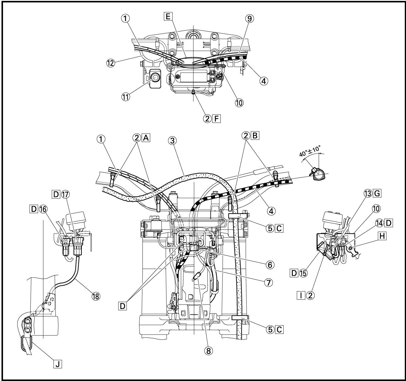
The following schedule is intended as a general guide to maintenance and lubrication. Bear in mind that such factors as weather, terrain, geographical location, and individual usage will alter the required maintenance and lubrication intervals. If you are a doubt as to what intervals to follow in maintaining and lubricating your machine, consult your Yamaha dealer.
* marked: For USA
| Item | After break-in | Every race | Every third (or 500 km) | Every fifth (or 1,000 km) | As required | Remarks |
| ENGINE OILReplace | ● | | | ● | | |
| VALVESCheck the valve clearancesInspectReplace | ● | | ● | ● | ● | The engine must be cold.Check the valve seats and valve stems for wear. |
| VALVE SPRINGSInspectReplace | | | | ● | ● | Check the free length and the tilt. |
| VALVE LIFTERSInspectReplace | | | | ● | ● | Check for scratches and wear. |
| CAMSHAFTSInspectReplace | | | | ● | ● | Inspect the camshaft surface.Inspect the decompression system |
| CAMSHAFT SPROCKETSInspectReplace | | | | ● | ● | Check for wear on the teeth and for damage. |
| PISTONInspectCleanReplace | | | | ● | ●●● | Inspect crackInspect carbon deposits and eliminate them. |
| PISTON RINGInspectReplace | | | | ●● | ● | Check ring end gap |
| PISTON PINInspectReplace | | | | ● | ● | |
| CYLINDER HEADInspect and clean | | | | ● | | Inspect carbon deposits and eliminate them.Change gasket |
| CYLINDERInspect and cleanReplace | | | | ● | ● | Inspect score marksInspect wear |
| CLUTCHInspect and adjustReplace | ● | ● | | | ● | Inspect housing, friction plate, clutch plate and spring |
| TRANSMISSIONInspectReplace bearing | | | | | ●● | |
| SHIFT FORK, SHIFT CAM, GUIDE BARInspect | | | | | ● | Inspect wear |
| ROTOR NUTRetighten | ● | | | ● | | |
| MUFFLERInspect and retightenCleanReplace | ● | ● | | ● | ● | * Whichever comes first |
| *SPARK ARRESTERClean | | | | | (Every six months)● | |
| CRANKInspect and clean | | | | ● | ● | |
| CARBURETORInspect, adjust and clean | ● | ● | | | | |
| AIR INDUCTION SYSTEMInspect and clean | ● | ● | | ● | ● | |
| SPARK PLUGInspect and cleanReplace | ● | | ● | | ● | |
| DRIVE CHAINLubricate, slack, alignmentReplace | ● | ● | | | ● | Use chain lubeChain slack: 48 ~ 58 mm(1.9 ~ 2.3 in) |
| COOLING SYSTEMCheck coolant level and leakageCheck radiator cap operationReplace coolantInspect hoses | ● | ● | | | ●● | Every two years |
| OUTSIDE NUTS AND BOLTSRetighten | ● | ● | | | | Refer to “STARTING AND BREAK-IN” section in the CHAPTER 1. |
| AIR FILTERClean and lubricateReplace | ● | ● | | | ● | Use foam air-filter oil or equivalent oil |
| OIL FILTERReplace | ● | | | ● | | |
| OIL STRAINER (frame)Clean | | | | ● | | |
| FRAMEClean and inspect | ● | ● | | | | |
| FUEL TANK, COCKClean and inspect | ● | | ● | | | |
| BRAKESAdjust lever position and pedal heightLubricate pivot pointCheck brake disc surfaceCheck fluid level and leakageRetighten brake disc bolts, caliper bolts, master cylinder bolts and union boltsReplace padsReplace brake fluid | ●●●●● | ●●●●● | | | ●● | Every one year |
| Item | After break-in | Every race | Every third (or 500 km) | Every fifth (or 1,000 km) | As re-quired | Remarks |
| FRONT FORKS | | | | | | |
| Inspect and adjust | ● | ● | | | | Suspension oil “S1” |
| Replace oil | ● | | | ● | ● |
| Replace oil seal | | | | | |
| FRONT FORK OIL SEAL AND DUST SEAL | | | | | | Lithium base grease |
| Clean and lube | ● | ● | | | |
| PROTECTOR GUIDE | | | | | | |
| Replace | | | | | ● | |
| REAR SHOCK ABSORBER | | | | | (After rain ride) | Molybdenum disulfide grease |
| Inspect and adjust | ● | ● | | |
| Lube | | | ● | | ● |
| Retighten | ● | ● | | | |
| DRIVE CHAIN GUARD AND ROLLERS | | | | | | |
| Inspect | ● | ● | | | | |
| SWINGARM | | | | | | Molybdenum disulfide grease |
| Inspect, lube and retighten | ● | ● | | | |
| RELAY ARM, CONNECTING ROD | | | | | | Molybdenum disulfide grease |
| Inspect, lube and retighten | ● | ● | | | |
| SIDESTAND Lubricate | | | | | ● | Lithium base grease |
| STEERING HEAD | | | | | | Lithium base grease |
| Inspect free play and retighten | ● | ● | | ● | ● |
| Clean and lube | | | | | |
| Replace bearing | | | | | |
| TIRE, WHEELS | | | | | | Lithium base grease |
| Inspect air pressure, wheel run-out, tire wear and spoke looseness | ● | ● | | | |
| Retighten sprocket bolt | ● | ● | | | |
| Inspect bearings | | | ● | | ● |
| Replace bearings Lubricate | | | ● | | |
| THROTTLE, CONTROL CABLE | | | | | | Yamaha cable lube or SAE 10W-30 motor oil |
| Check routing and connection | ● | ● | | | |
| Lubricate | ● | ● | | | |
| HOT STARTER, CLUTCH LEVER | | | | | ● | |
| Inspect free play | | | | | |
| BATTERY | | | | | ● | |
| Check terminal for looseness and corrosion | | | | | |
CONTROLES ET REGLAGES PERIODIQUES PROGRAMME D'ENTRETIEN
Before riding for break-in operation, practice or a race, make sure the machine is in good operating condition.
Before using this machine, check the following points.
GENERAL INSPECTION AND MAINTENANCE
| Item | Routine | Page |
| Coolant | Check that coolant is filled up to the radiator filler cap. Check the cooling system for leakage. | P.3-5 ~ 9 |
| Fuel | Check that a fresh gasoline is filled in the fuel tank. Check the fuel line for leakage. | P.1-21 |
| Engine oil | Check that the oil level is correct. Check the crankcase and oil line for leakage. | P.3-14 ~ 18 |
| Gear shifter and clutch | Check that gears can be shifted correctly in order and that the clutch operates smoothly. | P.3-9 ~ 10 |
| Throttle grip/Housing | Check that the throttle grip operation and free play are correctly adjusted. Lubricate the throttle grip and housing, if necessary. | P.3-10 ~ 11 |
| Brakes | Check the play of front brake and effect of front and rear brake. | P.3-25 ~ 31 |
| Chain | Check chain slack and alignment. Check that the chain is lubricated properly. | P.3-32 ~ 35 |
| Wheels | Check for excessive wear and tire pressure. Check for loose spokes and have no excessive play. | P.3-43 ~ 44 |
| Steering | Check that the handlebar can be turned smoothly and have no excessive play. | P.3-44 ~ 46 |
| Front forks and rear shock absorber | Check that they operate smoothly and there is no oil leakage. | P.3-35 ~ 42 |
| Cables (wires) | Check that the clutch and throttle cables move smoothly. Check that they are not caught when the handlebars are turned or when the front forks travel up and down. | — |
| Muffler | Check that the muffler is tightly mounted and has no cracks. | — |
| Sprocket | Check that the driven sprocket tightening bolt is not loose. | P.3-32 |
| Lubrication | Check for smooth operation. Lubricate if necessary. | P.3-47 |
| Bolts and nuts | Check the chassis and engine for loose bolts and nuts. | P.1-26 |
| Lead connectors | Check that the AC magneto, CDI unit, and ignition coil are connected tightly. | P.1-6 |
| Settings | Is the machine set suitably for the condition of the racing course and weather or by taking into account the results of test runs before racing? Are inspection and maintenance completely done? | P.7-1 ~ 20 |
CONTROLE ET ENTRETIEN AVANT UTILISATION
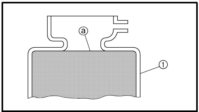
EC350000
ENGINE
COOLANT LEVEL INSPECTION
WARNING
Do not remove the radiator cap ①, drain bolt and hoses when the engine and radiator are hot. Scalding hot fluid and steam may be blown out under pressure, which could cause serious injury.
When the engine has cooled, place a thick towel over the radiator cap, slowly rotate the cap counterclockwise to the detent. This procedure allows any residual pressure to escape. When the hissing sound has stopped, press down on the cap while turning counterclockwise and remove it.
CAUTION:
Hard water or salt water is harmful to the engine parts. You may use distilled water, if you can't get soft water.
- Place the machine on a level place, and hold it in an upright position.
- Remove:
- Radiator cap
- Check:
- Coolant level ⓐ
Coolant level low → Add coolant.
① Radiator
COOLANT REPLACEMENT
WARNING
Do not remove the radiator cap when the engine is hot.
MOTEUR
CONTROLE DU NIVEAU DU LIQUIDE DE REFROIDISSEMENT
! AVERTISSEMENT
Take care so that coolant does not splash on painted surfaces. If it splashes, wash it away with water.
- Place a container under the engine.
-
Remove:
-
Seat
-
Left side cover
-
Remove the catch tank hose from the catch tank and drain the tank of its coolant.
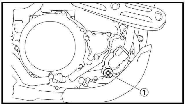
natural_image
Technical line drawing of a mechanical component with no visible text or symbols
- Remove:
- Coolant drain bolt ①
- Remove:
- Radiator cap
Drain the coolant completely.
- Clean:
- Cooling system
Thoroughly flush the cooling system with clean tap water.
-
Install:
-
Copper washer New
- Coolant drain bolt
10 Nm (1.0 m · kg, 7.2 ft · lb)
ATTENTION:
Recommended coolant: High quality ethylene glycol anti-freeze containing anti-corrosion for aluminum engine
Coolant ① and water
(soft water) ② mixing ratio: 50%/50%
Coolant capacity:
1.0 L (0.88 Imp qt, 1.06 US qt)
CAUTION:
- Do not mix more than one type of ethylene glycol antifreeze containing corrosion inhibitors for aluminum engine.
- Do not use water containing impurities or oil.
Handling notes of coolant:
The coolant is harmful so it should be handled with special care.
WARNING
- When coolant splashes to your eye. Thoroughly wash your eye with water and see your doctor.
- When coolant splashes to your clothes. Quickly wash it away with water and then with soap.
- When coolant is swallowed. Quickly make him vomit and take him to a doctor.
9. Install:
- Radiator cap
Start the engine and warm it up for a several minutes.
10. Check:
- Coolant level
Coolant level low → Add coolant.
CHANGEMENT DU LIQUIDE DE REFROIDISSEMENT KÜHLFLÜSSIGKEIT WECHSELN CAMBIO DEL REFRIGERANTE
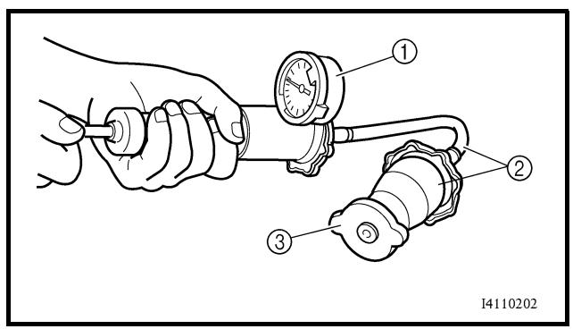
EC355000
RADIATOR CAP INSPECTION
1. Inspect:
- Seal (radiator cap) ①
- Valve and valve seat ②
Crack/damage → Replace.
Exist fur deposits ③ → Clean or replace.
EC356001
RADIATOR CAP OPENING PRESSURE INSPECTION
1. Attach:
- Radiator cap tester ① and adapter ②
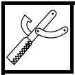
Radiator cap tester:
YU-24460-01/90890-01325
Adapter:
YU-33984/90890-01352
NOTE:
Apply water on the radiator cap seal.
③ Radiator cap
- Apply the specified pressure.

Radiator cap opening pressure: 110 kPa (1.1 kg/cm ^2 , 15.6 psi)
3. Inspect:
- Pressure
Impossible to maintain the specified pressure for 10 seconds → Replace.
CONTROLE DU BOUCHON DE RADIATEUR
1. Contrôler:
EC357002
COOLING SYSTEM INSPECTION
- Inspect:
- Coolant level
- Attach:
- Radiator cap tester ① and adapter ②
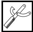
Radiator cap tester:
YU-24460-01/90890-01325
Adapter:
YU-33984/90890-01352
- Apply the specified pressure.

Standard pressure: 180 kPa (1.8 kg/cm ^2 , 25.6 psi)
NOTE:
- Pressure
Impossible to maintain the specified pressure for 10 seconds → Repair.
- Radiator
- Radiator hose joint
Coolant leakage → Repair or replace.
- Radiator hose
Swelling → Replace.
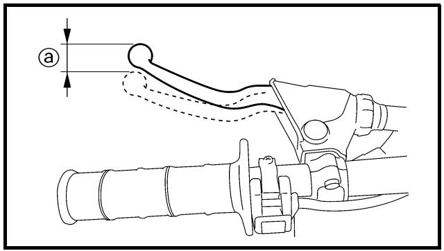
EC359020
CLUTCH ADJUSTMENT
- Check:
- Clutch lever free play @
Out of specification → Adjust.

Clutch lever free play ⓐ: 8 \~ 13 mm (0.31 \~ 0.51 in)
CONTROLE DU CIRCUIT DE REFROIDISSEMENT
- Contrôler:
2. Adjust:
- Clutch lever free play
Clutch lever free play adjustment steps:
- Loosen the locknut ①.
- Turn the adjuster ② until free play ⓐ is within the specified limits.
- Tighten the locknut.

Locknut:
4 Nm (0.4 m · kg, 2.9 ft · lb)
NOTE:
- Make minute adjustment on the lever side using the adjuster ③.
- After adjustment, check proper operation of clutch lever.
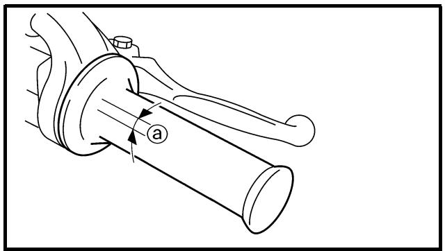
EC35A001
THROTTLE CABLE ADJUSTMENT
1. Check:
- Throttle grip free play @
Out of specification → Adjust.

Throttle grip free play ⓐ:
3 \~ 5 mm (0.12 \~ 0.20 in)
2. Adjust:
- Throttle grip free play
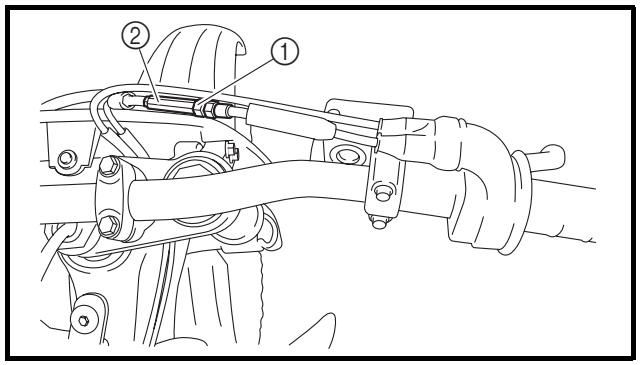
Throttle grip free play adjustment steps:
- Slide the adjuster cover.
- Loosen the locknut ①.
- Turn the adjuster ② until the specified free play is obtained.
- Tighten the locknut.

Locknut:
4 Nm (0.4 m • kg, 2.9 ft • lb)
NOTE:
Before adjusting the throttle cable free play, the engine idle speed should be adjusted.

WARNING
After adjusting the throttle cable free play, start the engine and turn the handlebar to right and left and make sure that the engine idling does not run faster.
2. Régler:
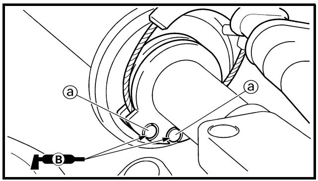
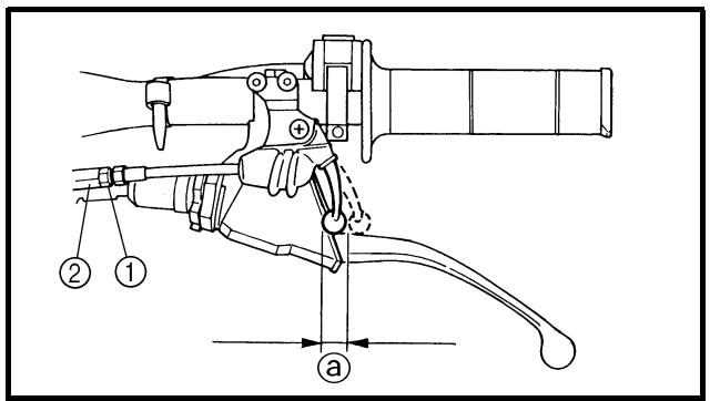
THROTTLE LUBRICATION
1. Remove:
- Cover (throttle cable cap) ①
- Cover (grip cap) ②
- Throttle cable cap ③
2. Apply:
- Lithium soap base grease
On the throttle cable end ⓐ.
3. Install:
- Throttle cable cap
- Screw (throttle cable cap)
4 Nm (0.4 m · kg, 2.9 ft · lb)
- Cover (grip cap)
- Cover (throttle cable cap)
HOT STARTER LEVER ADJUSTMENT
1. Check:
- Hot starter lever free play @
Out of specification → Adjust.

Hot starter lever free play ⓐ: 3 \~ 6 mm (0.12 \~ 0.24 in)
2. Adjust:
• Hot starter lever free play
| Hot starter lever free play adjustment steps:Loosen the locknut 1.Turn the adjuster 2 until free play @ is within the specified limits.Tighten the locknut. |
 | Locknut:4 Nm (0.4 m • kg, 2.9 ft • lb) |
NOTE:
After adjustment, check proper operation of hot starter.
GRAISSAGE DE L'ACCELERATEUR
Proper air filter maintenance is the biggest key to preventing premature engine wear and damage.
CAUTION:
Never run the engine without the air filter element in place; this would allow dirt and dust to enter the engine and cause rapid wear and possible engine damage.
- Open the air filter case cover ①
NOTE:
Loosen the quick screw ② and pull on it to open the air filter case cover.
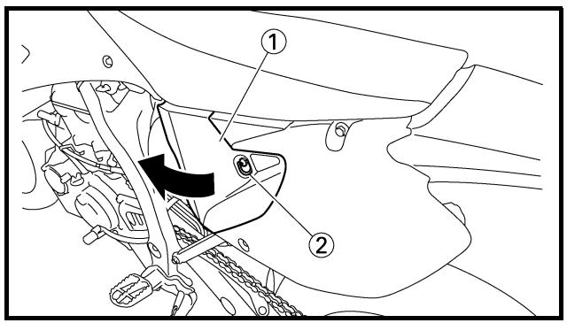
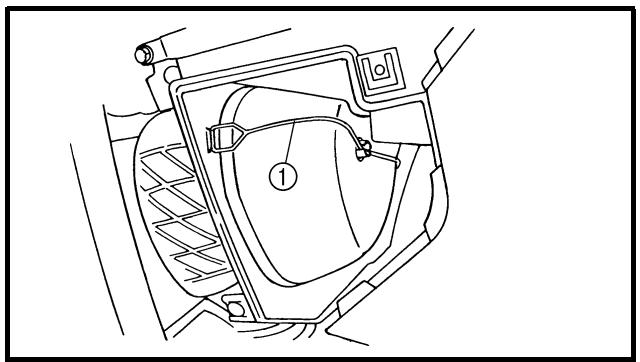
natural_image
Technical line drawing of a mechanical component with no visible text or symbols
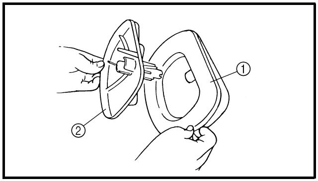
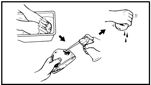
- Unhook:
- Binder ①
-
Remove:
-
Air filter element ①
-
Filter guide ②
-
Clean:
- Air filter element
Clean them with solvent.
NOTE:
After cleaning, remove the remaining solvent by squeezing the element.
NETTOYAGE DU FILTRE A AIR
N.B.:
- Air filter element
Damage → Replace.
- Apply:
- Foam-air-filter oil or equivalent oil to the element.
NOTE:
- Filter guide ①
NOTE:
- Air filter element ①
NOTE:
Align the projection ⓐ on filter guide with the hole ⓑ in air filter case.
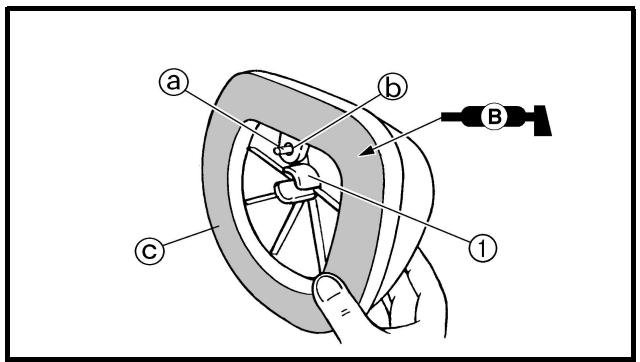
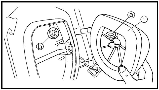
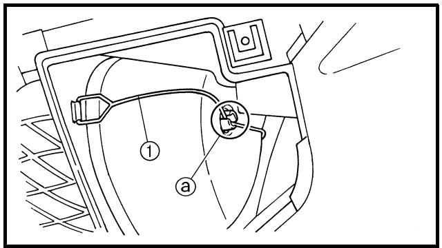
- Hook:
- Binder ①
NOTE:
Hook the binder ① so that it contacts the filter guide projections ⓐ.
ATTENTION:
- Stand the machine on a level surface.
NOTE:
- When checking the oil level make sure that the machine is upright.
- Place the machine on a suitable stand.
WARNING
Never remove the oil tank cap just after high speed operation. The heated oil could spurt out. causing danger. Wait until the oil cools down to approximately 70 °C (158 °F).
- Idle the engine more than 3 minutes while keeping the machine upright. Then stop the engine and inspect the oil level.
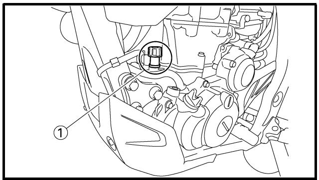

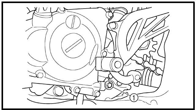
natural_image
Technical line drawing of a mechanical assembly with gears and levers (no text or symbols)
- Remove:
- Oil tank plug ①
- Inspect:
- Oil level
Check that the engine oil is above the level mark ⓐ and that the oil does not come out when the check bolt ① is removed.
Below the level mark ⓐ → Add oil through the filler cap hole until it is above the level mark ⓐ.
Oil comes out at the check bolt → Drain the oil until it stops coming out.
NOTE:
When inspecting the oil level, do not screw the oil level gauge into the oil tank.
Insert the gauge lightly.
CONTROLE DU NIVEAU D'HUILE MOTEUR
- Do not add any chemical additives. Engine oil also lubricates the clutch and additives could cause clutch slippage.
- Do not allow foreign material to enter the crankcase.
(Except for USA and CDN)

Recommended oil:
SAE10W30, SAE10W40,
SAE15W40, SAE20W40 or
SAE20W50
API service SG type or higher,
JASO standard MA
CAUTION:
CAUTION:
When the oil tank is empty, never start the engine.
(USA et CDN)

Huile recommandée:
Yamalube 4, SAE10W30
ou SAE20W40
Yamalube 4-R,
SAE10W50
API Service de type SG
et au-delà/JASO MA
ATTENTION:
-
Idle the engine more than 10 seconds while keeping the machine upright. Then stop the engine and add the oil to the maximum level.
-
Install:
- Oil tank plug
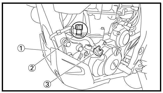
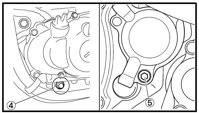
natural_image
Technical line drawing of a mechanical assembly showing internal components and a close-up view (no text or symbols)
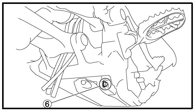
ENGINE OIL REPLACEMENT
- Start the engine and let it warm up for several minutes.
- Stop the engine and place an oil pan under the drain bolt.
- Remove:
- Engine guard ①
- Oil tank plug ②
- Oil filler cap ③
- Drain bolt (with gasket) ④
- Oil filter drain bolt (O-ring) ⑤
- Drain bolt (with gasket) ⑥
Drain the crankcase and oil tank of its oil.
- If the oil filter is to be replaced during this oil change, remove the following parts and reinstall them.
Replacement steps:
- Remove the oil filter cover ① and oil filter element ②.
- Check the O-rings ③, if cracked or damaged, replace them with a new one.
- Install the oil filter element and oil filter cover.

Oil filter cover:
10 Nm (1.0 m • kg, 7.2 ft • lb)
5. Install:
- Gaskets
New
- Oil filter drain bolt
10 Nm (1.0 m · kg, 7.2 ft · lb)
- Drain bolt (crankcase right)
- Drain bolt (crankcase left)
natural_image
Technical line drawing of a mechanical assembly with no visible text or symbols

Oil quantity:
Periodic oil change:
0.95 L (0.84 Imp qt, 1.00 US qt)
With oil filter replacement:
1.0 L (0.88 Imp qt, 1.06 US qt)
Total amount:
1.2 L (1.06 Imp qt, 1.27 US qt)
7. Install:
- Oil filler cap ①
8. Inspect:
- Engine (for oil leaks)
- Oil level
Refer to "ENGINE OIL LEVEL INSPECTION".
9. Check:
- Oil pressure
Checking steps:
- Slightly loosen the oil gallery bolt ①.
- Start the engine and keep it idling until oil starts to seep from the oil gallery bolt. If no oil comes out after one minute, turn the engine off so it will not seize.
- Check oil passages, oil filter and oil pump for damage or leakage.
- Start the engine after solving the problem(s) and recheck the oil pressure.
- Tighten the oil gallery bolt to specification.

Oil gallery bolt:
10 Nm (1.0 m • kg, 7.2 ft • lb)
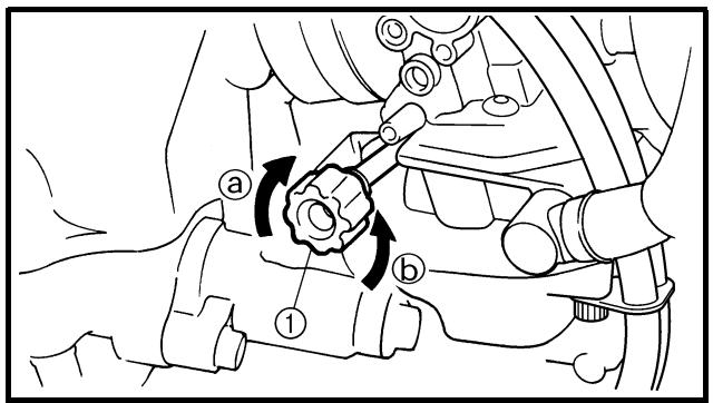
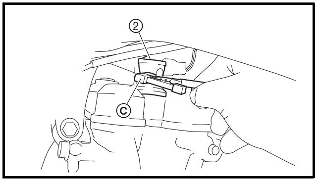
EC35M021
IDLE SPEED ADJUSTMENT
- Start the engine and thoroughly warm it up.
- Adjust:
- Idle speed
Adjustment steps:
- Turn the throttle stop screw ① until the specified engine idling speed.
NOTE:
Using a digital engine tachometer for idle speed adjustment, detect the engine idling speed by bringing the sensing element © of the engine tachometer close to the ignition coil ②.
To increase idle speed →
Turn the throttle stop screw ① in ⓐ.
To decrease idle speed →
Turn the throttle stop screw ① out ⑥.

Engine idling speed: 1,750 \~ 1,850 r/min
VALVE CLEARANCE ADJUSTMENT
NOTE:
- The valve clearance should be adjusted when the engine is cool to the touch.
- The piston must be at Top Dead Center (T.D.C.) on compression stroke to check or adjust the valve clearance.
1. Remove:
- Seat
- Fuel tank
Refer to “SEAT, FUEL TANK AND SIDE COVERS” section in the CHAPTER 4.
2. Remove:
- Air cut-off valve assembly
Refer to “AIR INDUCTION SYSTEM” section in the CHAPTER 4.
- Spark plug
- Engine stay (upper)
- Cylinder head cover
Refer to “CAMSHAFTS” section in the CHAPTER 4.
3. Remove:
- Timing plug ①
- Straight plug ②
- O-ring
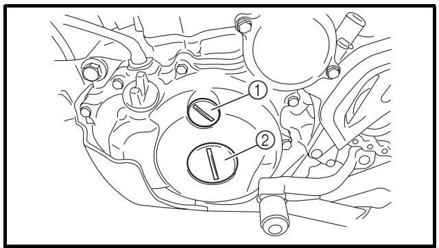

4. Check:
- Valve clearance
Out of specification → Adjust.

Valve clearance (cold):
Intake valve:
0.10 \~ 0.15 mm
(0.0039 \~ 0.0059 in)
Exhaust valve:
0.20 \~ 0.25 mm
(0.0079 \~ 0.0098 in)
Checking steps:
- Turn the crankshaft counterclockwise with a wrench.
- Align the T.D.C. mark ⓐ on the rotor with the align mark ⓑ on the crankcase cover when piston is at T.D.C. on compression stroke.
REGLAGE DU JEU AUX SOUPAPES
N.B.:
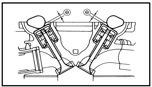
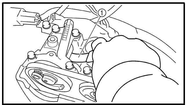
natural_image
Technical line drawing of a mechanical assembly with hands and components (no text or symbols)
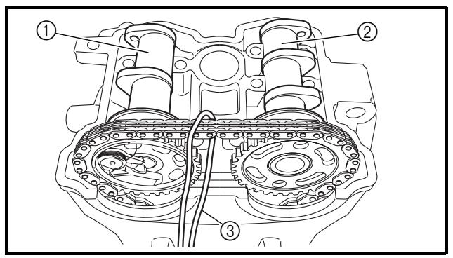
NOTE:
In order to be sure that the piston is at Top Dead Center, the punch mark © on the exhaust camshaft and the punch mark ⓐ on the intake camshaft must align with the cylinder head surface, as shown in the illustration.
- Measure the valve clearance ⓔ using a feeler gauge ①.
NOTE:
Record the measured reading if the clearance is incorrect.
5. Adjust:
- Valve clearance
Adjustment steps:
- Loosen the timing chain tensioner cap bolt.
- Remove the timing chain tensioner and camshaft caps.
NOTE:
Remove the camshaft cap bolts in a criss-cross pattern from the outside working inwards.
- Remove the camshaft (exhaust ① and intake ②).
NOTE:
Attach a wire ③ to the timing chain to prevent it from falling into the crankcase.
N.B.:
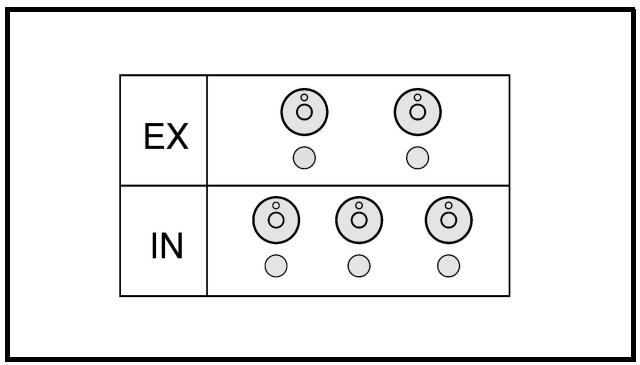
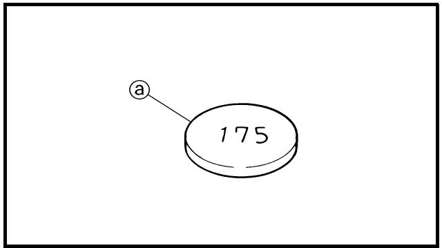
- Remove the valve lifters ④ and the pads ⑤.
- Place a rag in the timing chain space to prevent pads from falling into the crank-case.
- Identity each valve lifter and pad position very carefully so that they can be reinstalled in their original place.
- Select the proper pad using the pad selecting table.
NOTE:
| Pad range | Pad Availability: 25 increments |
| No. 120 ~ No. 240 | 1.20 mm ~ 2.40 mm | Pads are available in 0.05 mm increments |
| NOTE: |
| The thickness @ of each pad is indicated inhundreds of millimeters on the pad upper surface. |
| Round off the last digit of the installed pad number to the nearest increment. |
| Last digit of pad number | Rounded value |
| 0, 1 or 2 | 0 |
| 4, 5 or 6 | 5 |
| 8 or 9 | 10 |
| EXAMPLE: |
| Installed pad number = 148 |
| Rounded off value = 150 |
| NOTE: |
| Pads can only be selected in 0.05 mm increments. |
- Locate the rounded-off value and the measured valve clearance in the chart “PAD SELECTION TABLE”. The field where these two coordinates intersect shows the new pad number to use.
NOTE:
Use the new pad number only as a guide when verifying the valve clearance adjustment.
- Install the new pads ⑥ and the valve lifters ⑦.
NOTE:
- Apply the engine oil on the valve lifters.
- Apply the molybdenum disulfide oil on the valve stem ends.
- Valve lifter must turn smoothly when rotated with a finger.
- Be careful to reinstall valve lifters and pads in their original place.
- Install the camshafts (exhaust and intake), the timing chain and the camshaft caps. Refer to “CAMSHAFTS” section in the CHAPTER 4.

Bolt (camshaft cap): 10 Nm (1.0 m • kg, 7.2 ft • lb)
- Install the timing chain tensioner.
Refer to “CAMSHAFTS” section in the CHAPTER 4.
NOTE:
Turn the crankshaft counterclockwise several turns so that the installed parts settle into the right position.
- Recheck the valve clearance.
- If the clearance is still incorrect, repeat all the clearance adjustment steps until the specified clearance is obtained.
6. Install:
- All removed parts
NOTE:
Install all removed parts in reversed order of their removal.
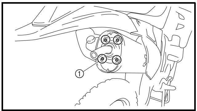
natural_image
Line drawing of a car interior showing steering wheel and dashboard (no text or symbols)
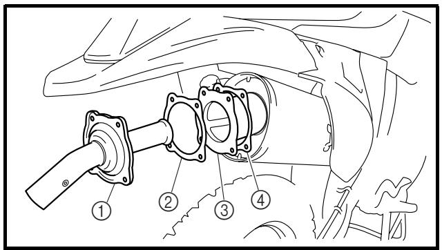
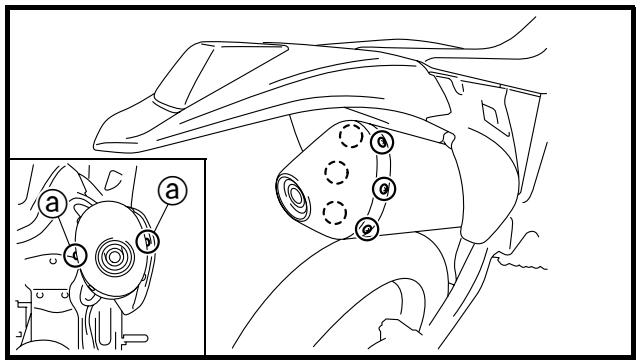
SPARK ARRESTER CLEANING (For USA)
WARNING
- Screw (silencer cap) ①
- Remove:
- Bolt (spark arrester) ①
-
Remove:
-
Tail pipe ①
- Gasket (tail pipe) ②
- Spark arrester ③
Pull the spark arrester out of the silencer.
-
Gasket (spark arrester) ④
-
Clean:
- Spark arrester Tap the spark arrester lightly, then use a wire brush to remove any carbon deposits.
-
Install:
-
Gasket (spark arrester)
- Spark arrester
Insert the spark arrester into the silencer and align the bolt holes.
- Gasket (tail pipe)
- Bolt (spark arrester)
7 Nm (0.7 m · kg, 5.1 ft · lb)
- Install:
- Silencer cap
5 Nm (0.5 m · kg, 3.6 ft · lb)
NOTE:
First tighten the two screws @ located horizontally apart, and then tighten the others.
NETTOYAGE DU PARE- ETINCELLES (USA)
! AVERTISSEMENT
Bleed the brake system if:
- The system has been disassembled.
- A brake hose has been loosened or removed.
• The brake fluid is very low.
- The brake operation is faulty.
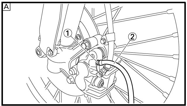
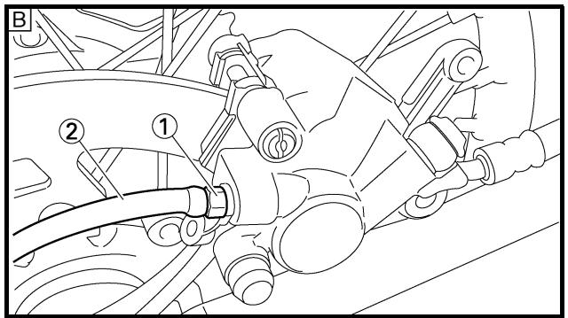
1. Remove:
- Master cylinder cap
- Diaphragm
- Reservoir float (front brake)
- Protector (rear brake)
2. Bleed:
- Brake fluid
A Front
B Rear
Air bleeding steps:
a. Add proper brake fluid to the reservoir.
b. Install the diaphragm. Be careful not to spill any fluid or allow the reservoir to overflow.
c. Connect the clear plastic tube ② tightly to the caliper bleed screw ①.
d. Place the other end of the tube into a container.
e. Slowly apply the brake lever or pedal several times.
f. Pull the lever in or push down on the pedal. Hold the lever or pedal in position.
g. Loosen the bleed screw and allow the lever or pedal to travel towards its limit.
h. Tighten the bleed screw when the lever or pedal limit has been reached; then release the lever or pedal.

Bleed screw:
6 Nm (0.6 m • kg, 4.3 ft • lb)
i. Repeat steps (e) to (h) until of the air bubbles have been removed from the system.
CHASSIS
PURGE D'AIR DU CIRCUIT DE FREINAGE
! AVERTISSEMENT
If bleeding is difficult, it may be necessary to let the brake fluid system stabilize for a few hours. Repeat the bleeding procedure when the tiny bubbles in the system have disappeared.
j. Add brake fluid to the level line on the reservoir.

WARNING
Check the operation of the brake after bleeding the brake system.
3. Install:
- Protector (rear brake)
- Reservoir float (front brake)
- Diaphragm
- Master cylinder cap
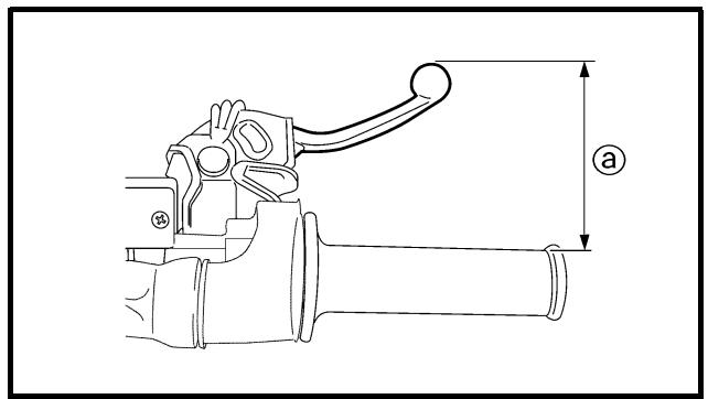
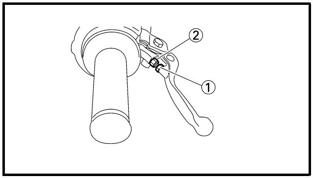
EC362040
| Brake lever position adjustment steps:Loosen the locknut 1.Turn the adjusting bolt 2 until the lever position @ is within specified position.Tighten the locknut. |
| Locknut:5 Nm (0.5 m • kg, 3.6 ft • lb) |
| CAUTION:Be sure to tighten the locknut, as it will cause poor brake performance. |
4. Install:
- Lever cover
N.B.:
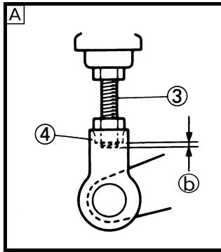
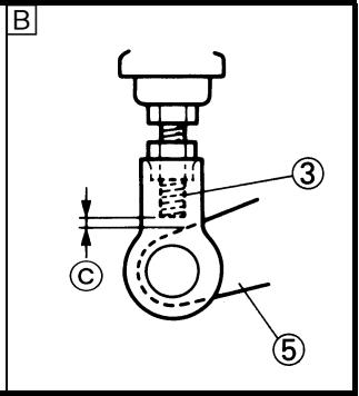
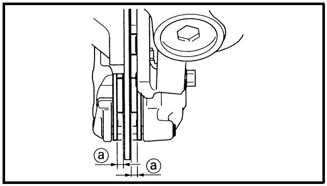
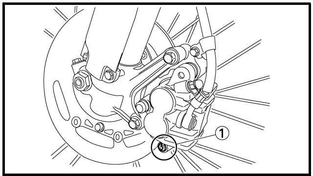
natural_image
Technical line drawing of a mechanical assembly with no visible text or symbols
EC364002 REAR BRAKE ADJUSTMENT
1. Check:
- Brake pedal height @
Out of specification → Adjust.

Brake pedal height ⓐ: 10 mm (0.39 in)
2. Adjust:
- Brake pedal height
Pedal height adjustment steps:
- Loosen the locknut ①.
- Turn the adjusting nut ② until the pedal height @ is within specified height.
- Tighten the locknut.

WARNING
- Adjust the pedal height between the maximum A and the minimum B as shown. (In this adjustment, the bolt ③ end ⑥ should protrude out of the threaded portion ④ but not be less than 2 mm (0.08 in) © away from the brake pedal ⑤).
• After the pedal height adjustment, make sure that the rear brake does not drag.
EC365080 FRONT BRAKE PAD INSPECTION AND REPLACEMENT
1. Inspect:
- Brake pad thickness @
Out of specification → Replace as a set.

Brake pad thickness ⓐ:
| Standard | |
| 4.4 mm (0.17 in) | 1.0 mm (0.04 in) |
2. Replace:
- Brake pad
Brake pad replacement steps:
- Remove the pad pin plug ①.
REGLAGE DU FREIN ARRIERE
- Contrôler:
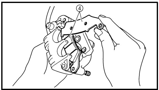
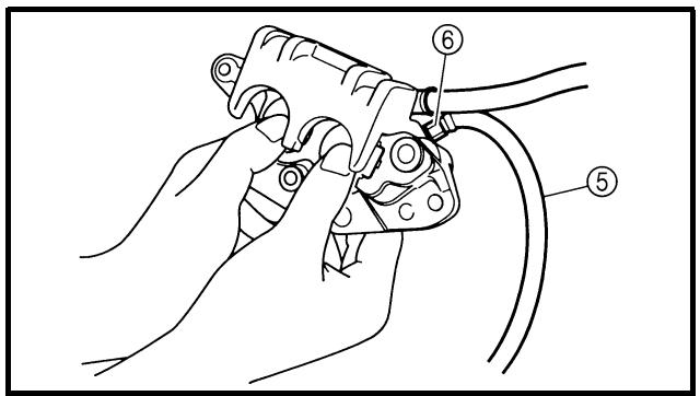
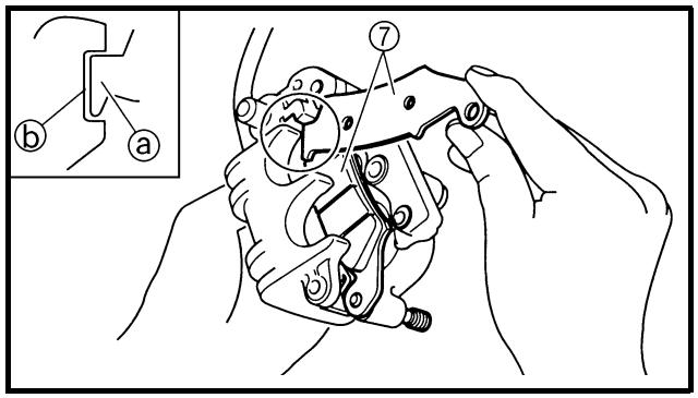
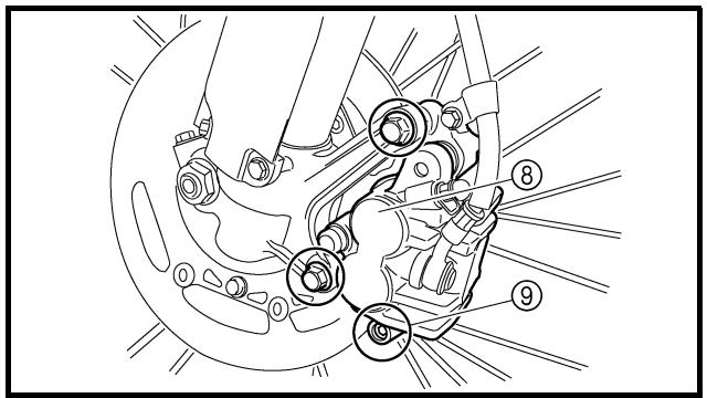
- Loosen the pad pin ②.
- Remove the caliper ③ from the front fork.
- Remove the pad pin and brake pads ④.
- Connect the transparent hose ⑤ to the bleed screw ⑥ and place the suitable container under its end.
- Loosen the bleed screw and push the caliper piston in.
CAUTION:
Do not reuse the drained brake fluid.
- Tighten the bleed screw.

Bleed screw:
6 Nm (0.6 m • kg, 4.3 ft • lb)
• Install the brake pads ⑦ and pad pin.
NOTE:
- Install the brake pads with their projections
① into the caliper recesses ②.
- Temporarily tighten the pad pin at this point.
- Install the caliper ⑧ and tighten the pad pin ⑨.

Bolt (caliper):
23 Nm (2.3 m • kg, 17 ft • lb)
Pad pin:
18 Nm (1.8 m • kg, 13 ft • lb)
natural_image
Technical line drawing of a bicycle brake system with no visible text or symbols
| • Install the pad pin plug 10. |
 | Pad pin plug:3 Nm (0.3 m • kg, 2.2 ft • lb) |
3. Inspect:
- Brake fluid level
Refer to "BRAKE FLUID LEVEL INSPECTION" section.
4. Check:
- Brake lever operation
A softly or spongy feeling → Bleed brake system.
Refer to "BRAKE SYSTEM AIR BLEEDING" section.
EC366060
REAR BRAKE PAD INSPECTION AND REPLACEMENT
1. Inspect:
- Brake pad thickness ⓐ
Out of specification → Replace as a set.
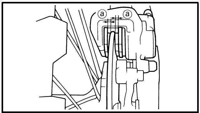
 Brake pad thickness @: Brake pad thickness @: |
| Standard | |
| 6.4 mm (0.25 in) | 1.0 mm (0.04 in) |
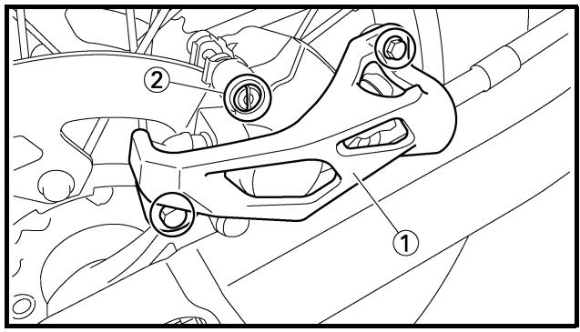
2. Replace:
- Brake pad
Brake pad replacement steps:
- Remove the protector ① and pad pin plug ②.
- Loosen the pad pin ③.
- Remove the rear wheel ④ and caliper ⑤. Refer to “FRONT WHEEL AND REAR WHEEL” section in the CHAPTER 5.
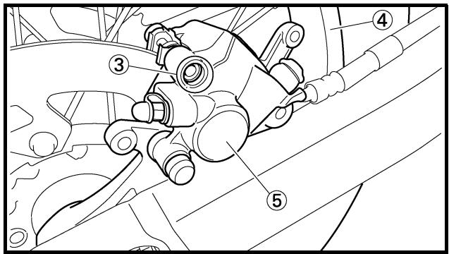
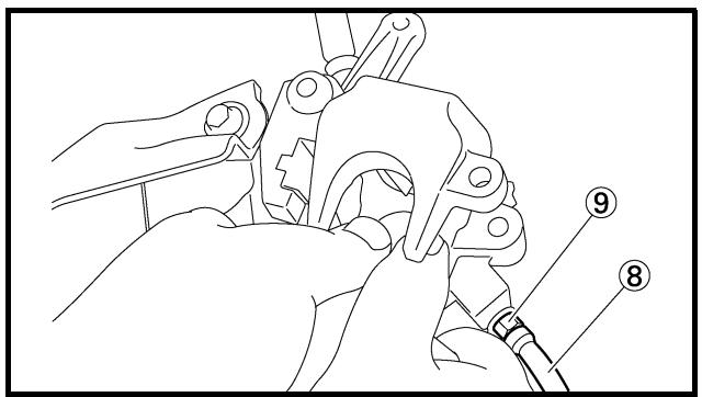
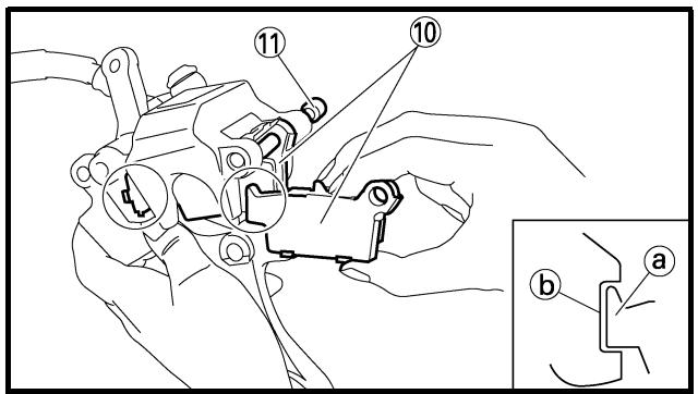
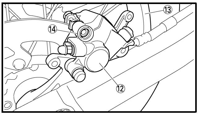
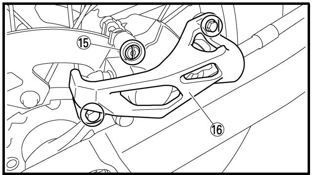
- Remove the pad pin ⑥ and brake pads ⑦.
- Connect the transparent hose ⑧ to the bleed screw ⑨ and place the suitable container under its end.
- Loosen the bleed screw and push the caliper piston in.
CAUTION:
Do not reuse the drained brake fluid.
- Tighten the bleed screw.

Bleed screw:
6 Nm (0.6 m • kg, 4.3 ft • lb)
- Install the brake pad ⑩ and pad pin ⑪.
NOTE:
- Install the brake pads with their projections
① into the caliper recesses ⑥.
- Temporarily tighten the pad pin at this point.
- Install the caliper ⑫ and rear wheel ⑬. Refer to “FRONT WHEEL AND REAR WHEEL” section in the CHAPTER 5.
- Tighten the pad pin ⑭.

Pad pin:
18 Nm (1.8 m • kg, 13 ft • lb)
- Install the pad pin plug ⑮ and protector ⑯.

Pad pin plug:
3 Nm (0.3 m • kg, 2.2 ft • lb)
Bolt (protector):
7 Nm (0.7 m • kg, 5.1 ft • lb)
natural_image
Technical line drawing of three mechanical clamping components (no text or symbols)
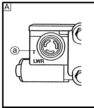
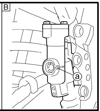
3. Inspect:
- Brake fluid level
Refer to “BRAKE FLUID LEVEL INSPECTION” section.
4. Check:
- Brake pedal operation
A softly or spongy feeling → Bleed brake system.
Refer to “BRAKE SYSTEM AIR BLEEDING” section.
EC36b000
REAR BRAKE PAD INSULATOR INSPECTION
1. Remove:
- Brake pad
Refer to “REAR BRAKE PAD INSPECTION AND REPLACEMENT” section.
2. Inspect:
- Rear brake pad insulator ① Damage → Replace.
EC367001
- Place the master cylinder so that its top is in a horizontal position.
2. Inspect:
- Brake fluid level
Fluid at lower level → Fill up.
① Lower level
A Front
B Rear

Recommended brake fluid: DOT #4
WARNING
- Sprocket teeth @ Excessive wear → Replace.
NOTE:
Replace the drive, driven sprockets and drive chain as a set.
DRIVE CHAIN INSPECTION
1. Measure:
- Drive chain length (15 links) ⓐ
Out of specification → Replace.

Drive chain length (15 links): : 239.3 mm (9.42 in)
NOTE:
- While measuring the drive chain length, push down on the drive chain to increase its tension.
- Measure the length between drive chain roller ① and ⑯ as shown.
- Perform this measurement at two or three different places.
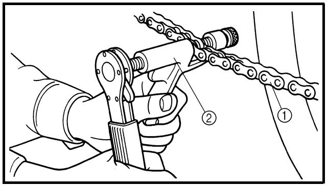
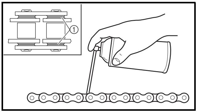
2. Remove:
- Drive chain ①
NOTE:
Remove the drive chain using a chain cutter ②.
3. Clean:
- Drive chain
Brush off as much dirt as possible.
Then clean the chain using the chain cleaner.
CAUTION:
This machine has a drive chain with small rubber O-rings ① between the side plates. Steam cleaning, high-pressure washes, certain solvent and kerosene can damage these O-rings.
CONTROLE DES PIGNONS
- Contrôler:
- Dents de pignon @
Usure excessive → Remplacer.
N.B.:
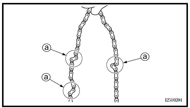
flowchart
graph TD
    A["Top Node"] --> B["Left Node"]
    B --> C["Right Node"]
    C --> D["Bottom Node"]
    style A fill:#f9f,stroke:#333
    style D fill:#bbf,stroke:#333
    note1["a"]
    note2["a"]
    note3["a"]
    note4["a"]
    note5["a"]
    note6["a"]
    note7["a"]
    note8["a"]
    note9["a"]
    note10["a"]
    note11["a"]
    note12["a"]
    note13["a"]
    note14["a"]
    note15["a"]
    note16["a"]
    note17["a"]
    note18["a"]
    note19["a"]
    note20["a"]
    note21["a"]
    note22["a"]
    note23["a"]
    note24["a"]
    note25["a"]
    note26["a"]
    note27["a"]
    note28["a"]
    note29["a"]
    note30["a"]
    note31["a"]
    note32["a"]
    note33["a"]
    note34["a"]
    note35["a"]
    note36["a"]
    note37["a"]
    note38["a"]
    note39["a"]
    note40["a"]
    note41["a"]
    note42["a"]
    note43["a"]
    note44["a"]
    note45["a"]
    note46["a"]
    note47["a"]
    note48["a"]
    note49["a"]
    note50["a"]
    note51["a"]
    note52["a"]
    note53["a"]
    note54["a"]
    note55["a"]
    note56["a"]
    note57["a"]
    note58["a"]
    note59["a"]
    note60["a"]
    note61["a"]
    note62["a"]
    note63["a"]
    note64["a"]
    note65["a"]
    note66["a"]
    note67["a"]
    note68["a"]
    note69["a"]
    note70["a"]
    note71["a"]
    note72["a"]
    note73["a"]
    note74["a"]
    note75["a"]
    note76["a"]
    note77["a"]
    note78["a"]
    note79["a"]
    note80["a"]
    note81["a"]
    note82["a"]
    note83["a"]
    note84["a"]
    note85["a"]
    note86["a"]
    note87["a"]
    note88["a"]
    note89["a"]
    note90["a"]
    note91["a"]
    note92["a"]
    note93["a"]
    note94["a"]
    note95["a"]
    note96["a"]
    note97["a"]
    note98["a"]
    note99["a"]
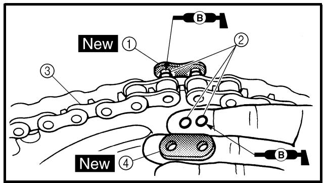
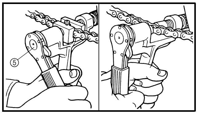
natural_image
Technical illustration showing two mechanical assembly steps: one for hand tooling a chain, the other for manual hand holding a chain (no text or symbols present)
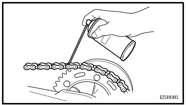
natural_image
Illustration of a hand using a tool to adjust a chain track with a gear (no text or symbols)
4. Inspect:
- O-ring ① (drive chain)
Damage → Replace the drive chain.
- Roller ②
- Side plate ③
Damage/wear → Replace the drive chain.
5. Check:
- Drive chain stiffness ⓐ
Clean and oil the chain and hold as illustrated.
Stiff → Replace the drive chain.
6. Install:
- Joint ① New
- O-ring ②
- Drive chain ③
NOTE:
When installing the drive chain, apply the lithium soap base grease on the joint and O-rings.
7. Install:
- Link plate ④ New
NOTE:
- Press the link plate onto the joint using a chain riveter ⑤.
- Rivet the end of the joint using a chain riveter.
- After riveting the joint, make sure its movement is smooth.
8. Lubricate:
- Drive chain
Drive chain lubricant: SAE 10W-30 motor oil or suitable chain lubricants
4. Contrôler:
DRIVE CHAIN SLACK ADJUSTMENT
- Elevate the rear wheel by placing the suitable stand under the engine.
- Check:
- Drive chain slack ⓐ
Above the seal guard installation bolt.
Out of specification → Adjust.
Drive chain slack:
48 \~ 58 mm (1.9 \~ 2.3 in)
NOTE:
Before checking and/or adjusting, rotate the rear wheel through several revolutions and check the slack several times to find the tightest point. Check and/or adjust the chain slack with the rear wheel in this “tight chain” position.
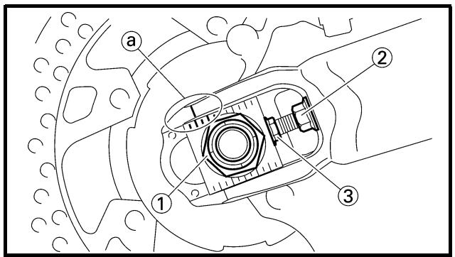
- Adjust:
- Drive chain slack
| Drive chain slack adjustment steps:Loosen the axle nut 1 and locknuts 2.Adjust the chain slack by turning the adjusters 3. |
| To tighten →Turn the adjuster 3 counterclockwise.To loosen →Turn the adjuster 3 clockwise and push wheel forward. |
| Turn each adjuster exactly the same amount to maintain correct axle alignment.(There are marks @ on each side of the chain puller alignment.)NOTE:Turn the adjuster so that the chain is in line with the sprocket, as viewed from the rear.CAUTION:Too small chain slack will overload the engine and other vital parts; keep the slack within the specified limits. |
REGLAGE DE LA TENSION DE LA CHAINE DE TRANSMISSION
natural_image
Technical line drawing of a motorcycle's front wheel and suspension mechanism (no text or symbols)
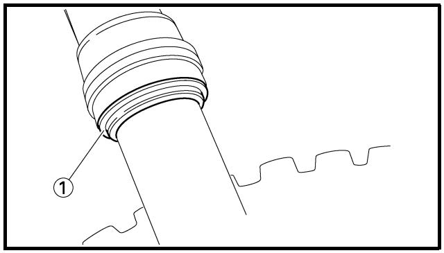
natural_image
Technical line drawing of a mechanical component with no visible text or symbols
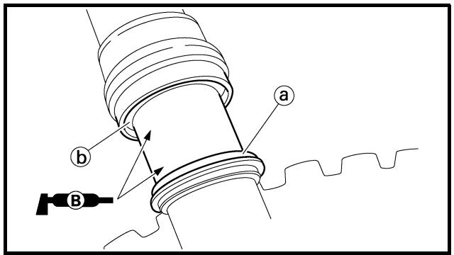
EC36C000
FRONT FORK INSPECTION
1. Inspect:
- Front fork smooth action
Operate the front brake and stroke the front fork.
Unsmooth action/oil leakage → Repair or replace.
EC36D001
FRONT FORK OIL SEAL AND DUST SEAL CLEANING
1. Remove:
NOTE:
Use a thin screw driver, and be careful not to damage the inner fork tube and dust seal.
2. Clean:
NOTE:
- Clean the dust seal and oil seal after every run.
- Apply the lithium soap base grease on the inner tube.
If the front fork initial movement feels stiff during a run, relieve the front fork internal pressure.
- Elevate the front wheel by placing a suitable stand under the engine.
- Remove the air bleed screw ① and release the internal pressure from the front fork.
- Install:
- Air bleed screw
1 Nm (0.1 m · kg, 0.7 ft · lb)
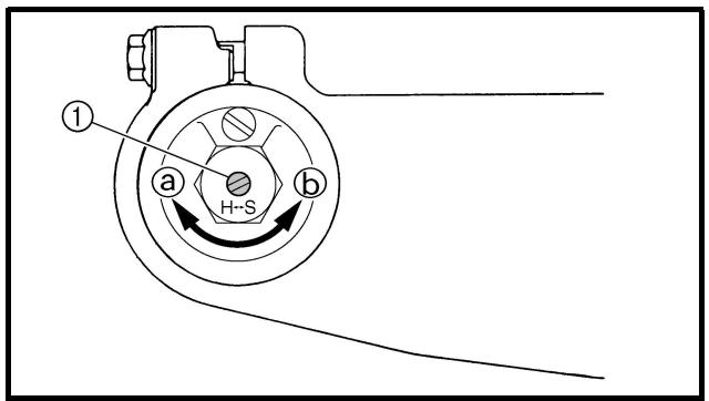
EC36H002
FRONT FORK REBOUND DAMPING FORCE ADJUSTMENT
1. Adjust:
- Rebound damping force
By turning the adjuster ①.
| Stiffer ⓐ → Increase the rebound damping force. (Turn the adjuster 1 in.) |
| Softer ⓑ → Decrease the rebound damping force. (Turn the adjuster 1 out.) |
 Extent of adjustment: Extent of adjustment: |
| Maximum | Minimum |
| Fully turned in position | 20 clicks out (from maximum position) |
REDUCTION DE LA PRESSION INTERNE DE LA FOURCHE
N.B.:
This is the position which is back by the specific number of clicks from the fully turned-in position.

Standard position: 8 clicks out
CAUTION:
Do not force the adjuster past the minimum or maximum extent of adjustment. The adjuster may be damaged.
WARNING
Always adjust each front fork to the same setting. Uneven adjustment can cause poor handling and loss of stability.
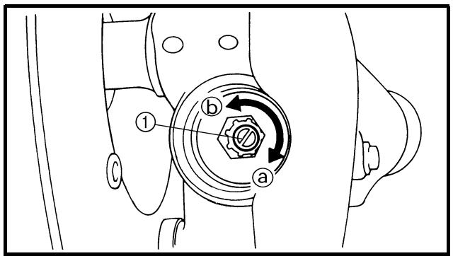
EC36J001
FRONT FORK COMPRESSION DAMPING FORCE ADJUSTMENT
- Remove:
- Rubber cap
- Adjust:
- Compression damping force
By turning the adjuster ①.
Stiffer ⓐ → Increase the compression damping force. (Turn the adjuster ① in.)
Softer ⑥ → Decrease the compression damping force. (Turn the adjuster ① out.)

Extent of adjustment:
| Maximum | Minimum |
| Fully turned in position | 20 clicks out (from maximum position) |
REGLAGE DE LA FORCE D'AMORTISSEMENT A LA COMPRESSION DE LA FOURCHE DRUCKSTUFEN-DÄMPFUNGSKRAFT DER TELESKOPGABEL EINSTELLEN AJUSTE DE LA AMORTIGUACIÓN EN COMPRESIÓN DE LA HORQUILLA DELANTERA
INSP ADJ
[NO TEXT]
- POSITION STANDARD:
This is the position which is back by the specific number of clicks from the fully turned-in position.
![YAMAHA WR450F-2007 - [NO TEXT] - 1](/content/2019/11/114880/images/07b0a4607b2ff1cae577e853ec46eca2f0a71fac44e5ba604ac722681223299f.jpg)
Standard position: 9 clicks out
CAUTION:
Do not force the adjuster past the minimum or maximum extent of adjustment. The adjuster may be damaged.
WARNING
Always adjust each front fork to the same setting. Uneven adjustment can cause poor handling and loss of stability.
- Install:
- Rubber cap
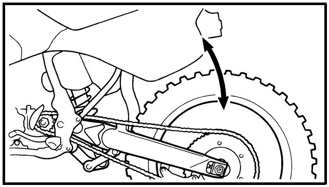
natural_image
Mechanical assembly diagram showing a gear and chain mechanism with no visible text or symbols
EC36K000
REAR SHOCK ABSORBER INSPECTION
-
Inspect:
-
Swingarm smooth action
Abnormal noise/unsmooth action → Grease the pivoting points or repair the pivoting points.
Damage/oil leakage → Replace.
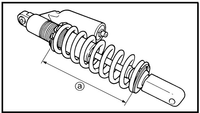
natural_image
Technical line drawing of a mechanical spring assembly with dimension label (a), no text or symbols present
REAR SHOCK ABSORBER SPRING PRELOAD ADJUSTMENT
- Elevate the rear wheel by placing the suitable stand under the engine.
- Remove:
- Rear frame
- Loosen:
- Locknut ①
- Adjust:
- Spring preload
By turning the adjuster ②.
| Stiffer → Increase the spring preload.(Turn the adjuster 2 in.) |
| Softer → Decrease the spring preload.(Turn the adjuster 2 out.) |
| Spring length (installed) a: |
| Standard length | Extent of adjustment |
| 252.5 mm (9.94 in)* 251.5 mm (9.90 in) | 238.5 ~ 258.5 mm(9.39 ~ 10.18 in) |
* For EUROPE
NOTE:
- Be sure to remove all dirt and mud from around the locknut and adjuster before adjustment.
- The length of the spring (installed) changes 1.5 mm (0.06 in) per turn of the adjuster.
CAUTION:
Never attempt to turn the adjuster beyond the maximum or minimum setting.
- Tighten:
- Locknut
- Install:
- Rear frame (upper)
- Rear frame (lower)
38 Nm (3.8 m · kg, 27 ft · lb)
32 Nm (3.2 m · kg, 23 ft · lb)
REGLAGE DE LA PRECONTRAINTE DU RESSORT DE L'AMORTISSEUR ARRIERE
- Rebound damping force
By turning the adjuster ①.
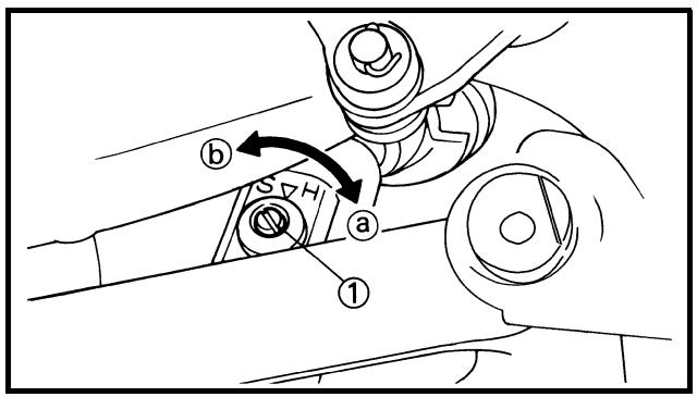
Stiffer ① → Increase the rebound damping force. (Turn the adjuster ① in.)
Softer ② → Decrease the rebound damping force. (Turn the adjuster ① out.)

Extent of adjustment:
| Maximum | Minimum |
| Fully turned in position | 20 clicks out (from maximum position) |
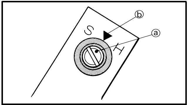
• STANDARD POSITION:
This is the position which is back by the specific number of clicks from the fully turned-in position. (Which align the punch mark ⓐ on the adjuster with the punch mark ⓑ on the bracket.)

Standard position: About 11 clicks out
CAUTION:
Do not force the adjuster past the minimum or maximum extent of adjustment. The adjuster may be damaged.
REGLAGE DE LA FORCE D'AMORTISSEMENT A LA DETENTE DE L'AMORTISSEUR ARRIERE
1. Régler:
- Low compression damping force
By turning the adjuster ①.
Stiffer ⓐ → Increase the low compression damping force. (Turn the adjuster ① in.)
Softer ⑥ → Decrease the low compression damping force. (Turn the adjuster ① out.)

Extent of adjustment:
| Maximum | Minimum |
| Fully turned in position | 20 clicks out (from maximum position) |
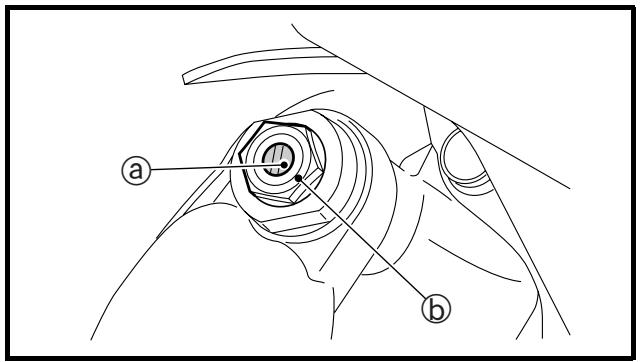
• STANDARD POSITION:
This is the position which is back by the specific number of clicks from the fully turned-in position. (Which align the punch mark ⓐ on the adjuster with the punch mark ⓑ on the high compression damping adjuster.)

Standard position:
About 8 clicks out
*About 11 clicks out
**About 9 clicks out
* For EUROPE
** For AUS, NZ and ZA
CAUTION:
Do not force the adjuster past the minimum or maximum extent of adjustment. The adjuster may be damaged.
REGLAGE DE LA FORCE D'AMORTISSEMENT A LA COMPRESSION BASSE DE L'AMORTISSEUR ARRIERE
1. Régler:
EC36d000
REAR SHOCK ABSORBER HIGH COMPRESSION DAMPING FORCE ADJUSTMENT
1. Adjust:
- High compression damping force
By turning the adjuster ①.
Stiffer ⓐ → Increase the high compression damping force. (Turn the adjuster ① in.)
Softer ⑥ → Decrease the high compression damping force. (Turn the adjuster ① out.)

Extent of adjustment:
| Maximum | Minimum |
| Fully turned in position | 2 turns out (from maximum position) |

• STANDARD POSITION:
This is the position which is back by the specific number of turns from the fully turned-in position. (Which align the punch mark ⓐ on the adjuster with the punch mark ⓑ on the adjuster body.)

Standard position: About 1-1/8 turns out * About 1-1/4 turns out
* For AUS, NZ and ZA
CAUTION:
Do not force the adjuster past the minimum or maximum extent of adjustment. The adjuster may be damaged.
REGLAGE DE LA FORCE D'AMORTISSEMENT A LA COMPRESSION HAUTE DE L'AMORTISSEUR ARRIERE
1. Régler:
natural_image
Illustration of hands adjusting a pressure gauge with a tool (no text or symbols present)
EC36Q000
TIRE PRESSURE CHECK
1. Measure:
- Tire pressure
Out of specification → Adjust.

Standard tire pressure: 100 kPa (1.0 kgf/cm ^2 , 15 psi)
NOTE:
- Check the tire while it is cold.
- Loose bead stoppers allow the tire to slip off its position on the rim when the tire pressure is low.
- A tilted tire valve stem indicates that the tire slips off its position on the rim.
- If the tire valve stem is found tilted, the tire is considered to be slipping off its position. Correct the tire position.
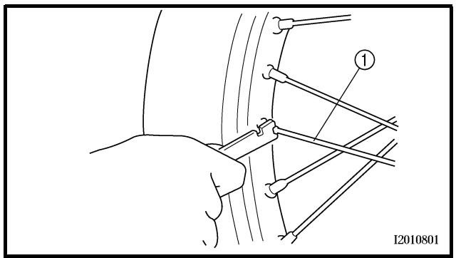
EC36S002
SPOKES INSPECTION AND TIGHTENING
1. Inspect:
- Spokes ①
Bend/damage → Replace.
Loose spoke → Retighten.
2. Tighten:
- Spokes
3 Nm (0.3 m · kg, 2.2 ft · lb)
NOTE:
Be sure to retighten these spokes before and after break-in. After a practice or a race check spokes for looseness.
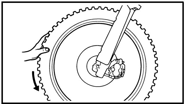
natural_image
Mechanical diagram showing a hand operating a gear and rotating a wheel with a tool, no text or symbols present.
EC36T000
WHEEL INSPECTION
1. Inspect:
- Wheel runout
Elevate the wheel and turn it.
Abnormal runout → Replace.
CONTROLE DE LA PRESSION DES PNEUS
- Mesurer:
natural_image
Mechanical diagram showing a hand operating a gear with rotating components and motion arrows (no text or symbols)
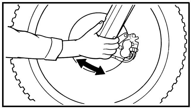
natural_image
Diagram of a hand using a tool to lift a car wheel, showing motion arrows (no text or symbols)
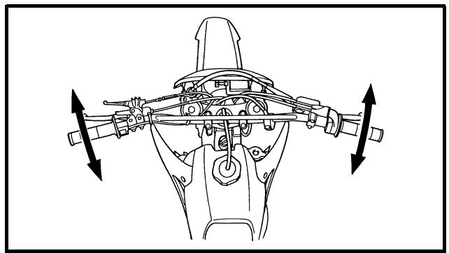
natural_image
Technical line drawing of a mechanical assembly with directional arrows indicating movement or force (no text or symbols)
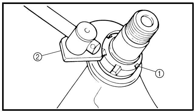
2. Inspect:
- Bearing free play
Exist play → Replace.
STEERING HEAD INSPECTION AND ADJUSTMENT
- Elevate the front wheel by placing a suitable stand under the engine.
2. Check:
- Steering shaft
Grasp the bottom of the forks and gently rock the fork assembly back and forth.
Free play → Adjust steering head.
3. Check:
- Steering smooth action
Turn the handlebar lock to lock.
Unsmooth action → Adjust steering ring nut.
4. Adjust:
- Steering ring nut
| Steering ring nut adjustment steps:Remove the headlight.Remove the handlebar and handle crown.Loosen the ring nut 1 using the ring nut wrench 2. |
 | Ring nut wrench:YU-33975/90890-01403 |
|
CONTROLE ET REGLAGE DE LA TETE DE FOURCHE LENKKOPFLAGER KONTROLLIEREN UND EINSTELLEN REVISIÓN Y AJUSTE DE LA COLUMNÁ DE LA DIRECCIÓN
2. Contrôler:
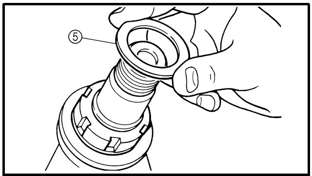
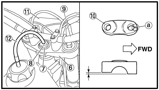
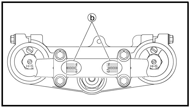
- Tighten the ring nut ③ using ring nut wrench ④.
NOTE:
- Apply the lithium soap base grease on the thread of the steering shaft.
- Set the torque wrench to the ring nut wrench so that they form a right angle.

Ring nut wrench:
YU-33975/90890-01403

Ring nut (initial tightening): 38 Nm (3.8 m • kg, 27 ft • lb)
- Loosen the ring nut one turn.
- Retighten the ring nut using the ring nut wrench.

WARNING
Avoid over-tightening.

Ring nut (final tightening): 7 Nm (0.7 m • kg, 5.1 ft • lb)
- Check the steering shaft by turning it lock to lock. If there is any binding, remove the steering shaft assembly and inspect the steering bearings.
- Install the plain washer ⑤, handle crown ⑥, plain washer ⑦, steering shaft nut ⑧, handlebar ⑨, handlebar holder (upper) ⑩ and headlight ⑪.
NOTE:
- The handlebar holder (upper) should be installed with the punched mark ⓐ forward.
- Install the handlebar so that the marks ⑥ are in place on both sides.
CONTROLE ET REGLAGE DE LA TETE DE FOURCHE LENKKOPFLAGER KONTROLLIEREN UND EINSTELLEN REVISIÓN Y AJUSTE DE LA COLUMNÁ DE LA DIRECCIÓN
Hakenschlüssel:
YU-33975/90890-01403

- Install the handlebar so that the projection © of the handlebar holder (upper) is positioned at the mark on the handlebar as shown.
- Insert the end of the fuel breather hose ⑫ into the hole in the steering shaft.
CAUTION:
First tighten the bolts on the front side of the handlebar holder (upper), and then tighten the bolts on the rear side.
Steering shaft nut:
145 Nm (14.5 m • kg, 105 ft • lb)
Handlebar holder (upper):
28 Nm (2.8 m • kg, 20 ft • lb)
Pinch bolt (handle crown):
21 Nm (2.1 m • kg, 15 ft • lb)
Headlight:
7 Nm (0.7 m • kg, 5.1 ft • lb)
To ensure smooth operation of all components, lubricate your machine during setup, after break-in, and after every race.
① All control cable
② Clutch lever pivot
③ Shift pedal pivot
④ Footrest pivot
⑤ Throttle-to-handlebar contact
⑥ Drive chain
⑦ Tube guide cable winding portion
⑧ Throttle cable end
⑨ Clutch cable end
⑩ Hot starter cable end
A Use Yamaha cable lube or equivalent on these areas.
B Use SAE 10W-30 motor oil or suitable chain lubricants.
C Lubricate the following areas with high quality, lightweight lithium-soap base grease.
CAUTION:
Wipe off any excess grease, and avoid getting grease on the brake discs.
LUBRIFICATION
Normal condition is a medium to light tan color.
Distinctly different color → Check the engine condition.
NOTE:
When the engine runs for many hours at low speeds, the spark plug insulator will become sooty, even if the engine and carburetor are in good operating condition.
- Measure:
- Plug gap ⓐ
Use a wire gauge or thickness gauge.
Out of specification → Regap.

Spark plug gap:
0.7 \~ 0.8 mm (0.028 \~ 0.031 in)
- Clean the plug with a spark plug cleaner if necessary.
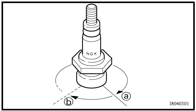
- Tighten:
- Spark plug
13 Nm (1.3 m · kg, 9.4 ft · lb)
NOTE:
- Before installing a spark plug, clean the gasket surface and plug surface.
- Finger-tighten ⓐ the spark plug before torquing to specification ⓑ.
PARTIE ELECTRIQUE CONTROLE DE LA BOUGIE
- Déposer:
- Bougie
- Contrôler:
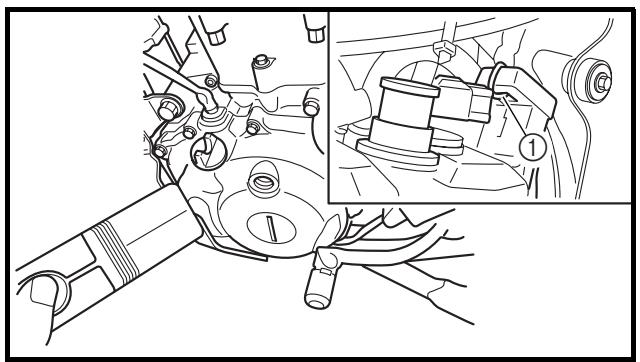
natural_image
Technical line drawing of a mechanical assembly with an inset showing a close-up of a component (no text or symbols present)
IGNITION TIMING CHECK
1. Remove:
- Timing plug ①
2. Attach:
- Timing light
- Inductive tachometer
To the ignition coil lead (orange lead ①).
Timing light:
YM-33277-A/90890-03141
3. Adjust:
- Engine idling speed
Refer to "IDLE SPEED ADJUSTMENT".
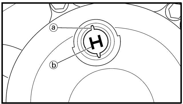
4. Check:
- Ignition timing
Visually check the stationary pointer ⓐ is within the firing range ⓑ on the rotor.
Incorrect firing range → Check rotor and pickup assembly.
5. Install:
- Timing plug
CONTROLE DE L'AVANCE A L'ALLUMAGE
1. Déposer:
Batteries generate explosive hydrogen gas and contain electrolyte which is made of poisonous and highly caustic sulfuric acid. Therefore, always follow these preventive measures:
- Wear protective eye gear when handling or working near batteries.
- Charge batteries in a well-ventilated area.
- Keep batteries away from fire, sparks or open flames (e.g., welding equipment, lighted cigarettes).
- DO NOT SMOKE when charging or handling batteries.
- KEEP BATTERIES AND ELECTROLYTE OUT OF REACH OF CHILDREN.
- Avoid bodily contact with electrolyte as it can cause severe burns or permanent eye injury.
- Skin — Wash with water.
- Eyes — Flush with water for 15 minutes and get immediate medical attention.
- Drink large quantities of water or milk followed with milk of magnesia, beaten egg or vegetable oil. Get immediate medical attention.
INTERNAL
CAUTION:
Charging time, charging amperage and charging voltage for an MF battery are different from those of conventional batteries. The MF battery should be charged as explained in the charging method illustrations. If the battery is overcharged, the electrolyte level will drop considerably. Therefore, take special care when charging the battery.
CONTROLE ET CHARGE DE LA BATTERIE
! AVERTISSEMENT
Since MF batteries are sealed, it is not possible to check the charge state of the battery by measuring the specific gravity of the electrolyte. Therefore, the charge of the battery has to be checked by measuring the voltage at the battery terminals.
1. Remove:
- Seat
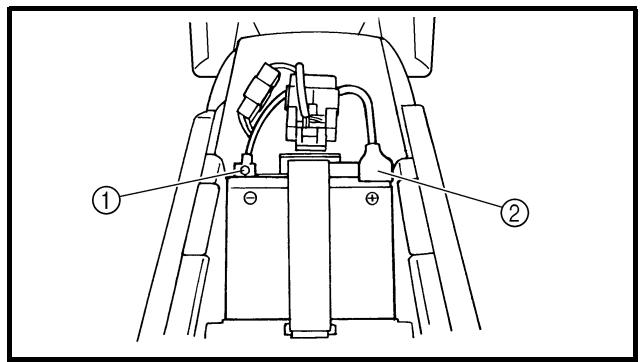
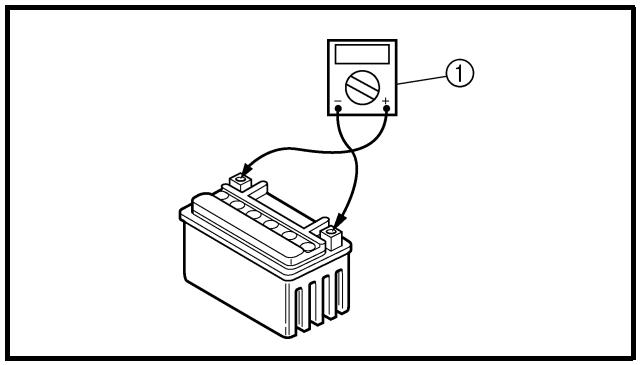
2. Disconnect:
- Battery leads
(from the battery terminals)
CAUTION:
First, disconnect the negative battery lead ①, and then the positive battery lead ②.
3. Remove:
- Battery band
- Battery
4. Measure:
- Battery charge
Measurement steps:
- Connect a pocket tester ① to the battery terminals.
Tester positive probe →
battery positive terminal
Tester negative probe →
battery negative terminal
NOTE:
- The charge state of an MF battery can be checked by measuring its open-circuit voltage (i.e., the voltage when the positive terminal is disconnected).
- No charging is necessary when the open-circuit voltage equals or exceeds 12.8 V.
CONTROLE ET CHARGE DE LA BATTERIE BATTERIE KONTROLLIEREN UND LADEN COMPROBACIÓN Y CARGA DE LA BATERÍA
N.B.:
- Check the charge of the battery, as shown in the charts and the following example.
Example
Open-circuit voltage = 12.0 V
Charging time = 6.5 hours
Charge of the battery = 20 \~ 30%
A Relationship between the open-circuit voltage and the charging time at 20 °C (68 °F) (These values vary with the temperature, the condition of the battery plates, and the electrolyte level.)
B Open-circuit voltage
C Charging time (hours)
D Time (minutes)
E Charging condition of the battery
F Ambient temperature 20 °C (68 °F)
① Charging
⑥ Check the open-circuit voltage.
- Charge:
- Battery
(refer to the appropriate charging method illustration)
WARNING
Do not quick charge a battery.
CAUTION:
- Never remove the MF battery sealing caps.
- Do not use a high-rate battery charger since it forces a high-amperage current into the battery quickly and can cause battery overheating and battery plate damage.
- If it is impossible to regulate the charging current on the battery charger, be careful not to overcharge the battery.
- When charging a battery, be sure to remove it from the machine. (If charging has to be done with the battery mounted on the machine, disconnect the negative battery lead from the battery terminal.)
- To reduce the chance of sparks, do not plug in the battery charger until the battery charger leads are connected to the battery.
Charging method using a variable voltage charger
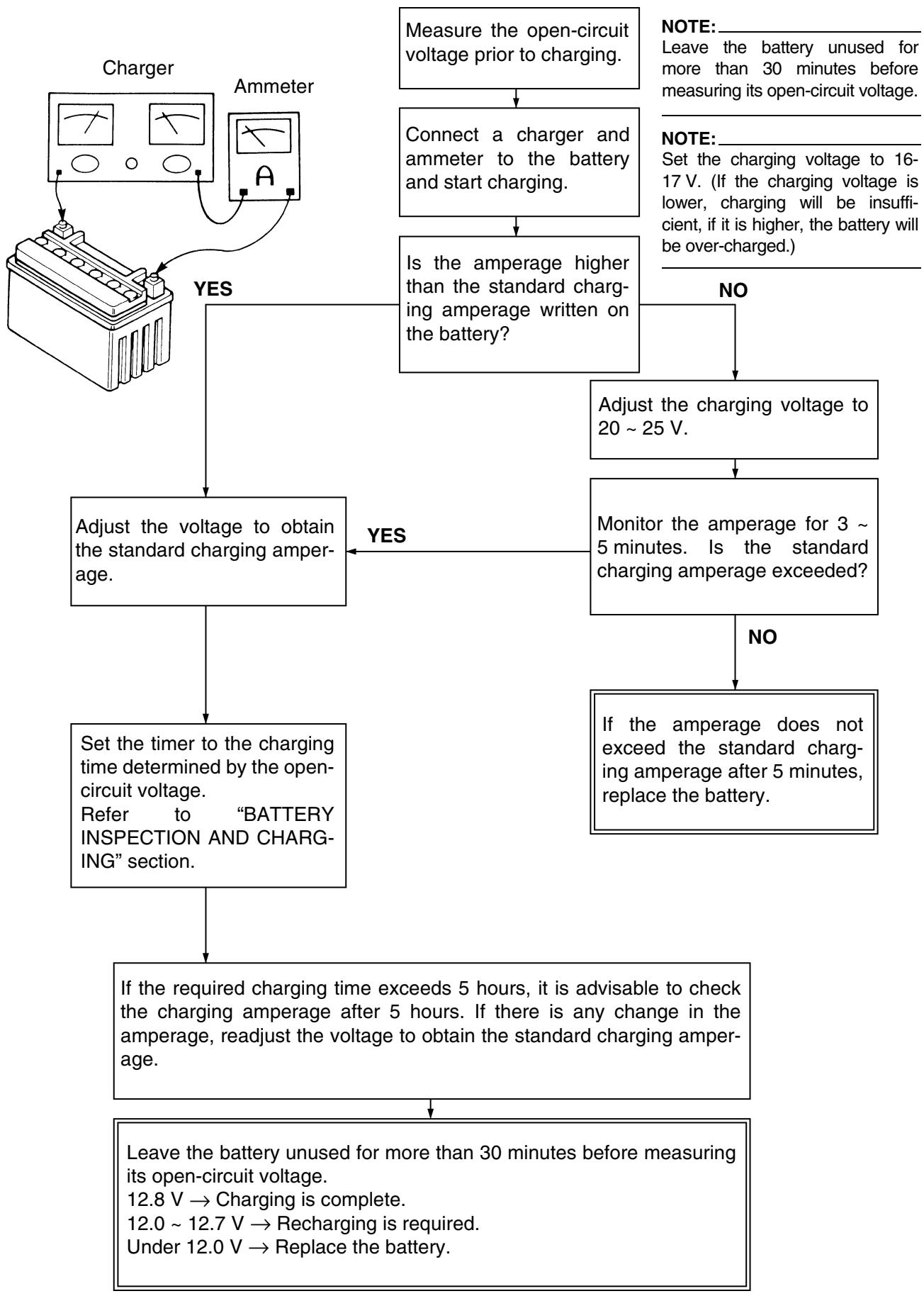
flowchart
graph TD
A["Charger"] -->|YES| B["Adjust the voltage to obtain the standard charging amperage."]
A -->|NO| C["Adjust the charging voltage to 20 ~ 25 V."]
B --> D["Set the timer to the charging time determined by the open-circuit voltage.<br>Refer to "BATTERY INSPECTION AND CHARGING" section."]
D --> E["If the required charging time exceeds 5 hours, it is advisable to check the charging amperage after 5 hours. If there is any change in the amperage, readjust the voltage to obtain the standard charging amperage."]
E --> F["Leave the battery unused for more than 30 minutes before measuring its open-circuit voltage.<br>12.8 V → Charging is complete.<br>12.0 ~ 12.7 V → Recharging is required.<br>Under 12.0 V → Replace the battery."]
F --> G["If the amperage does not exceed the standard charging amperage after 5 minutes, replace the battery."]
G --> H["Monitor the amperage for 3 ~ 5 minutes. Is the standard charging amperage exceeded?"]
H --> I["Adjust the charging voltage to 20 ~ 25 V."]
I --> J["Is the amperage higher than the standard charging amperage written on the battery?"]
J --> K["Connect a charger and ammeter to the battery and start charging."]
K --> L["Measure the open-circuit voltage prior to charging."]
L --> M["NOTE: Leave the battery unused for more than 30 minutes before measuring its open-circuit voltage."]
M --> N["NOTE: Set the charging voltage to 16-17 V. (If the charging voltage is lower, charging will be insufficient, if it is higher, the battery will be over-charged.)"]
Charging method using a constant voltage charger
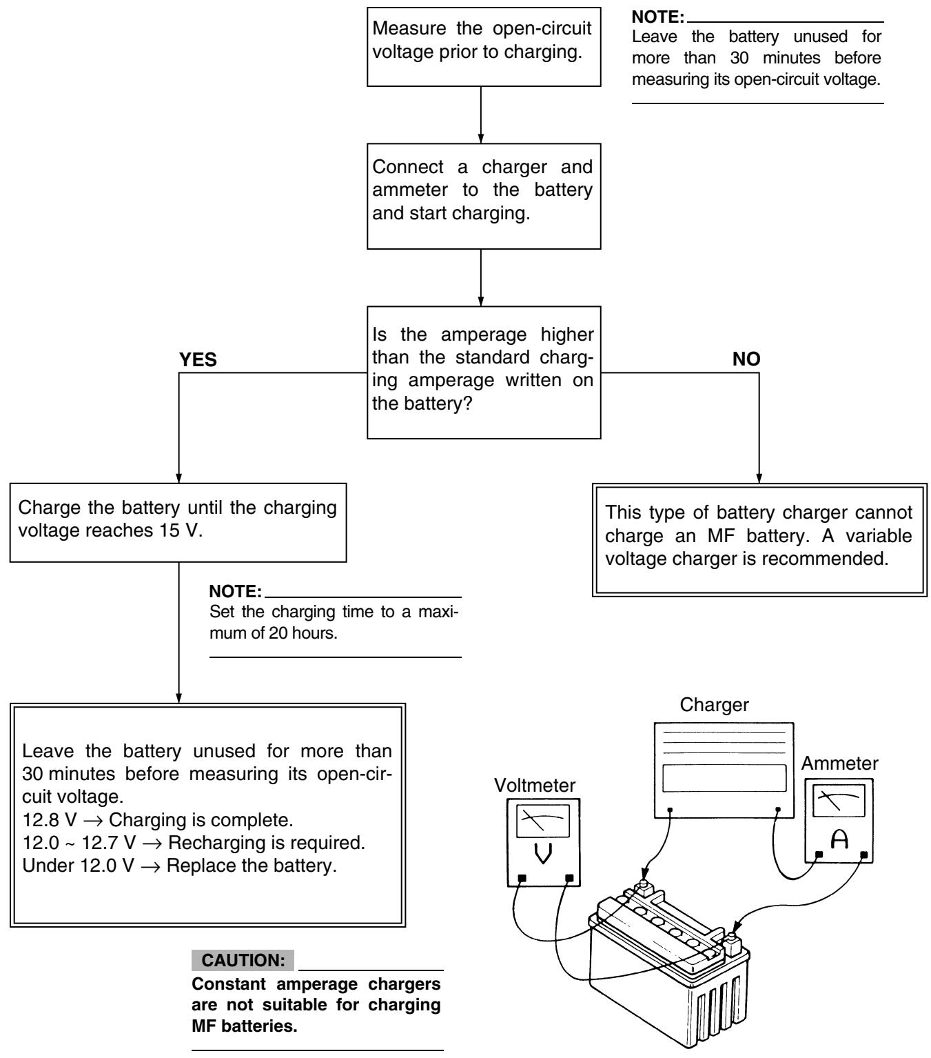
flowchart
graph TD
    A["Measure the open-circuit voltage prior to charging."] --> B["Connect a charger and ammeter to the battery and start charging."]
    B --> C{Is the amperage higher than the standard charging amperage written on the battery?}
    C -->|YES| D["Charge the battery until the charging voltage reaches 15 V."]
    C -->|NO| E["This type of battery charger cannot charge an MF battery. A variable voltage charger is recommended."]
    D --> F["Leave the battery unused for more than 30 minutes before measuring its open-circuit voltage.<br>12.8 V → Charging is complete.<br>12.0 ~ 12.7 V → Recharging is required.<br>Under 12.0 V → Replace the battery."]
    F --> G["CAUTION: Constant amperage chargers are not suitable for charging MF batteries."]
    E --> H["Voltmeter"]
    E --> I["Charger"]
    I --> J["Ammeter"]
    J --> K["NOTE: Leave the battery unused for more than 30 minutes before measuring its open-circuit voltage."]
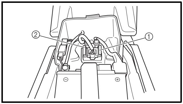
-
Install:
-
Battery
-
Battery band
-
Connect:
- Battery leads (to the battery terminals)
CAUTION:
First, connect the positive lead ①, then the negative lead ②.
-
Check:
-
Battery terminals
Dirt → Clean with a wire brush.
Loose connection → Connect properly.
-
Lubricate:
- Battery terminal
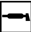
Recommended lubricant: Lithium soap base grease
- Install:
- Seat
EAS00181
FUSE INSPECTION
CAUTION:
To avoid a short circuit, always set the main switch to “OFF” when checking or replacing a fuse.
- Remove:
- Seat
- Fuse cover
- Check:
- Continuity
Checking steps:
- Remove the fuse ①.
- Connect the pocket tester to the fuse and check the continuity.
NOTE:
Set the pocket tester selector to “Ω × 1”.

Pocket tester:
YU-3112-C/90890-03112
- If the pocket tester indicates “∞”, replace the fuse.
② Reserve fuse
natural_image
Pure electrical circuit lines without any symbols
3. Replace:
- Blown fuse
Replacement steps:
- Set the main switch to "OFF".
• Install a new fuse of the correct amperage.
- Set on the switches to verify if the electrical circuit is operational.
- If the fuse immediately blows again, check the electrical circuit.
| Items | Amperage rating | Q’ty |
| Main fuse | 10 A | 1 |
WARNING
Never use a fuse with an amperage rating other than that specified. Improvising or using a fuse with the wrong amperage rating may cause extensive damage to the electrical system, cause the starting and ignition systems to malfunction and could possibly cause a fire.
4. Install:
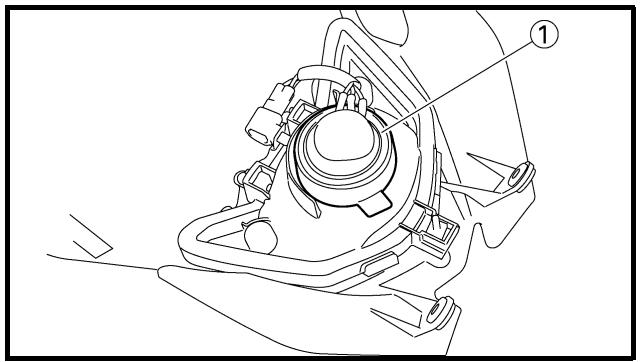
natural_image
Technical line drawing of a mechanical assembly with labeled component (1), no readable text or symbols present
REPLACING THE HEADLIGHT BULBS
1. Remove:
- Headlight
Refer to “SEAT, FUEL TANK AND SIDE COVERS” section in the CHAPTER 4.
2. Remove:
- Headlight bulb holder cover ①
3. Remove:
- Headlight bulb holder ①
NOTE:
Remove the headlight bulb holder by pushing it in and turning it counterclockwise.
REMPLACEMENT DES AMPOULES DE PHARE SCHEINWERFERLAMPE ERNEUERN CAMBIO DE LAS BOMBILLAS DEL FARO
3. Remplacer:
- Fusible grillé
Since the headlight bulb gets extremely hot, keep flammable products and your hands away from the bulb unit it has cooled down.
5. Install:
- Headlight bulb
New
CAUTION:
Avoid touching the glass part of the head-light bulb to keep it free form oil, otherwise the transparency of the glass, the life of the bulb and the luminous flux will be adversely affected. If the headlight bulb gets soiled, thoroughly clean it with a cloth moistened with alcohol or lacquer thinner.
6. Install:
- Headlight bulb holder
7. Install:
• Headlight bulb holder cover
8. Install:
- Headlight 7 Nm (0.7 m · kg, 5.1 ft · lb)
Refer to “SEAT, FUEL TANK AND SIDE COVERS” section in the CHAPTER 4.
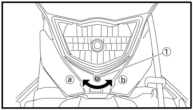
ADJUSTING THE HEADLIGHT BEAMS
1. Adjust:
- Headlight beam (vertically)
| Adjusting steps:• Turn the adjusting screw 1 in direction a or b. |
| Direction a | Headlight beam is raised. |
| Direction b | Headlight beam is lowered. |
① Seat removal
③ Side covers removal
② Fuel tank removal
④ Headlight removal
| Extent of removal | Order | Part name | Q'ty | Remarks |
| Preparation for removal | | SEAT, FUEL TANK AND SIDE COVERS REMOVALTurn the fuel cock to “OFF”.Disconnect the fuel hose. | | |
 | | 1 | Seat | 1 | Open the air filter case cover.Refer to “REMOVAL POINTS”. |
| 2 | Air scoop (left and right) | 2 |
| 3 | Bolt (fuel tank) | 2 |
| 4 | Fuel tank | 1 |
| 5 | Side cover (left) | 1 |
| 6 | Side cover (right) | 1 |
| 7 | Headlight coupler | 1 |
| 8 | Headlight | 1 |
MOTEUR
SELLE, RESERVOIR DE CARBURANT ET CACHES LATERAUX

REMOVAL POINTS
Side cover
1. Remove:
- Bolt (side cover)
- Side cover (right) ①
NOTE:
Draw the side cover backward to remove it because its claw ⓐ is inserted in the air filter case.
SELLE, RESERVOIR DE CARBURANT ET CACHES LATERAUX SITZBANK, KRAFTSTOFFTANK UND SEITENABDECKUNGEN SILLÍN, DEPÓSITO DE COMBUSTIBLE Y CUBIERTAS LATERALES
POINTS DE DEPOSE
Cache latéral
Extent of removal:
① Silencer removal
② Exhaust pipe removal
| Extent of removal | Order | Part name | Q'ty | Remarks |
| Preparation for removal | | EXHAUST PIPE AND SILENCER REMOVALSide cover (right) | | Refer to “SEAT, FUEL TANK AND SIDE COVERS” section. |
 | 1 | Bolt (clamp) | 1 | Only loosening. |
| 2 | Bolt [silencer (front)] | 1 |
| 3 | Bolt [silencer (rear)] | 1 |
| 4 | Collar | 1 |
| 5 | Silencer | 1 |
| 6 | Clamp | 1 |
| 7 | Nut (exhaust pipe) | 1 |
| 8 | Bolt (exhaust pipe) | 1 |
| 9 | Exhaust pipe | 1 |
| 10 | Gasket | 2 |
TUBE D'ECHAPPEMENT ET SILENCIEUX AUSPUFFKRÜMMER UND SCHALLDÄMPFER TUBO DE ESCAPE Y SILENCIADOR
TUBE D'ECHAPPEMENT ET SILENCIEUX
natural_image
Technical line drawing of a pipe fitting with a separate inset showing a ring and a labeled part (1), no text or symbols present.
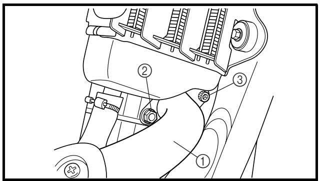
INSPECTION
Exhaust pipe and silencer
1. Inspect:
- Gasket ①
Damage → Replace.
ASSEMBLY AND INSTALLATION
Exhaust pipe and silencer
1. Install:
- Gasket New
- Exhaust pipe ①
- Nut (exhaust pipe) ②
20 Nm (2.0 m · kg, 1.4 ft · lb)
- Bolt (exhaust pipe) ③
First, temporarily tighten the nut (exhaust pipe), then tighten the bolt (exhaust pipe) 13 Nm (1.3 m • kg, 9.4 ft • lb). After that, retighten the nut (exhaust pipe) 20 Nm (2.0 m • kg, 14 ft • lb) and then the bolt (exhaust pipe) 20 Nm (2.0 m • kg, 14 ft • lb).
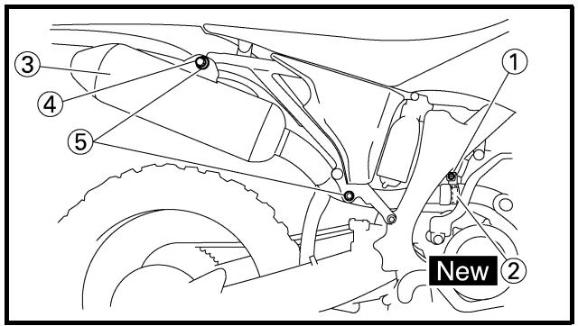
2. Install:
- Clamp ①
16 Nm (1.6 m · kg, 11 ft · lb)
- Gasket ② New
- Silencer ③
- Plain washer ④
- Bolt (silencer) ⑤
30 Nm (3.0 m · kg, 22 ft · lb)
TUBE D'ECHAPPEMENT ET SILENCIEUX AUSPUFFKRÜMMER UND SCHALLDÄMPFER TUBO DE ESCAPE Y SILENCIADOR
CONTROLE
Extent of removal:
① Radiator removal
② Coolant reservoir removal
| Extent of removal | Order | Part name | Q'ty | Remarks |
| Preparation for removal | | RADIATOR REMOVALDrain the coolant.Seat, fuel tank and side coverExhaust pipe | | Refer to “COOLANT REPLACEMENT” section in the CHAPTER 3.Refer to “SEAT, FUEL TANK AND SIDE COVERS” section.Refer to “EXHAUST PIPE AND SILENCER” section. |
| [64E2] | 1 | Panel | 2 | |
| 2 | Clamp | 8 | |
| 3 | Radiator (right) | 1 | |
| 4 | Hose 2 | 1 | |
| 5 | Hose 3 | 1 | |
| 6 | Hose 4 | 1 | |
| 7 | Pipe 2/O-ring | 1/1 | |
| 8 | Catch tank hose | 1 | |
| 9 | Radiator (left) | 1 | |
| 10 | Hose 1 | 1 | |
| 11 | Pipe 1/O-ring | 1/1 | |
| 12 | Catch tank breather hose | 1 | |
| 13 | Catch tank | 1 | |
RADIATEUR
Do not remove the radiator cap when the engine and radiator are hot. Scalding hot fluid and steam may be blown out under pressure, which could cause serious injury.
When the engine has cooled, open the radiator cap by the following procedure:
Place a thick rag, like a towel, over the radiator cap, slowly rotate the cap counterclockwise to the detent. This procedure allows any residual pressure to escape. When the hissing sound has stopped, press down on the cap while turning counterclockwise and remove it.
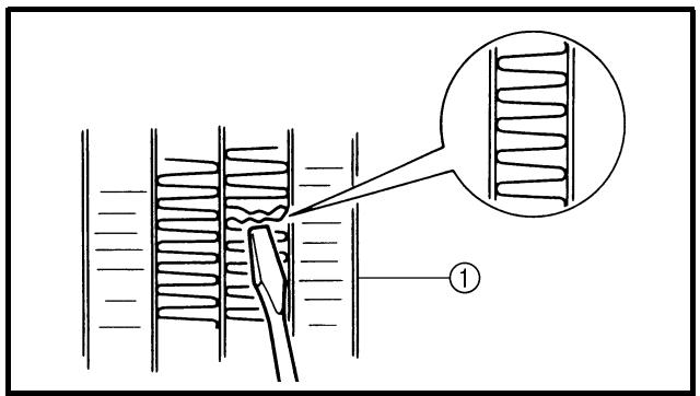
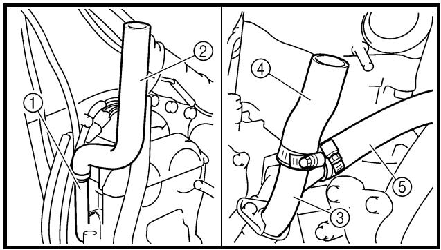
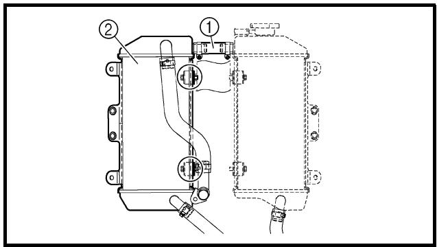
EC454000
INSPECTION
EC444100
Radiator
1. Inspect:
- Radiator core ①
Obstruction → Blow out with compressed air through rear of the radiator.
Bent fin → Repair/replace.
EC455000
ASSEMBLY AND INSTALLATION
Radiator
1. Install:
- Pipe 1 ①
- Hose 1 ②
- Pipe 2 ③
- Hose 3 ④
- Hose 4 ⑤
10 Nm (1.0 m · kg, 7.2 ft · lb)
2 Nm (0.2 m · kg, 1.4 ft · lb)
10 Nm (1.0 m · kg, 7.2 ft · lb)
2 Nm (0.2 m · kg, 1.4 ft · lb)
2 Nm (0.2 m · kg, 1.4 ft · lb)
2. Install:
- Hose 2 ① 2 Nm (0.2 m · kg, 1.4 ft · lb)
- Radiator (left) ②
10 Nm (1.0 m · kg, 7.2 ft · lb)
REMARQUES CONCERNANT LA MANIPULATION
! AVERTISSEMENT
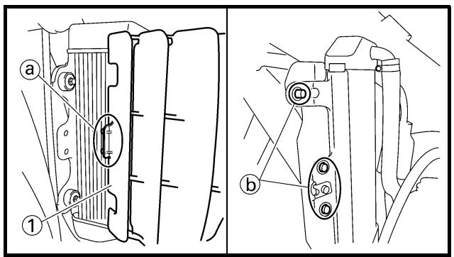
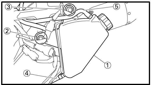
3. Install:
- Catch tank hose ①
- Radiator (right) ②
10 Nm (1.0 m · kg, 7.2 ft · lb)
Refer to "CABLE ROUTING DIAGRAM" section in the CHAPTER 2.
4. Install:
- Panel ①
NOTE:
First fit the inner hook portion ⓐ and then the outer one ⓑ onto the radiator.
5. Install:
- Catch tank ①
- Bolt (catch tank) ②
7 Nm (0.7 m · kg, 5.1 ft · lb)
- Bolt (catch tank) ③
16 Nm (1.6 m · kg, 11 ft · lb)
- Catch tank hose ④
- Catcher tank breather hose ⑤
Refer to “CABLE ROUTING DIAGRAM” section in the CHAPTER 2.
3. Monter:
Extent of removal:
① Carburetor removal
| Extent of removal | Order | Part name | Q'ty | Remarks |
| Preparation for removal | | CARBURETOR REMOVALFuel tankRear shock absorber | | Refer to “SEAT, FUEL TANK AND SIDE COVERS” section.Refer to “REAR SHOCK ABSORBER” section in the CHAPTER 5. |
| 1 | 1 | Clamp | 2 | |
| 2 | TPS coupler | 1 | |
| 3 | Throttle cable cover | 1 | |
| 4 | Throttle cable | 2 | |
| 5 | Clamp (air cleaner joint) | 1 | Loosen the screw (air cleaner joint). |
| 6 | Clamp (carburetor joint) | 1 | Loosen the screws (carburetor joint). |
| 7 | Hot starter plunger | 1 | |
| 8 | Carburetor | 1 | |
| 9 | Cylinder head breather pipe | 1 | |
| 10 | Cylinder head breather hose 1 | 1 | |
CARBURATEUR
Extent of removal:
① Carburetor removal
Extent of removal:
① Carburetor disassembly
| Extent of removal | Order | Part name | Q'ty | Remarks |
| | CARBURETOR DISASSEMBLY | | |
| 1 | Breather hose | 4 | |
| 2 | Valve lever housing cover | 1 | |
| 3 | Screw (throttle shaft) | 1 | |
| 4 | Throttle valve | 1 | |
| 5 | Needle holder | 1 | |
| 6 | Jet needle | 1 | |
| 7 | Cover | 1 | |
| 8 | Spring | 1 | |
| 9 | Diaphragm (accelerator pump) | 1 | |
| 10 | Air cut valve cover | 1 | |
| 11 | Spring (air cut valve) | 1 | |
| 12 | Diaphragm (air cut valve) | 1 | |
| 13 | Float chamber | 1 | |
| 14 | Leak jet | 1 | |
| 15 | Float pin | 1 | |
| 16 | Float | 1 | |
DEMONTAGE DU CARBURATEUR
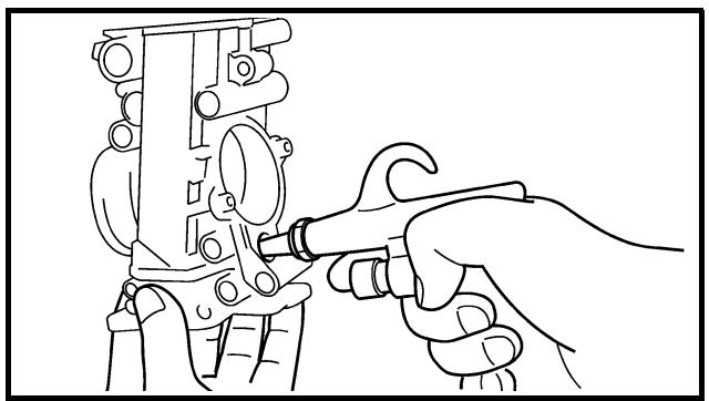
natural_image
Line drawing of a hand using a tool to adjust or install a mechanical component (no text or symbols present)
EC466020
HANDLING NOTE
CAUTION:
Do not loosen the screw {TPS (throttle position sensor)} ① except when changing the TPS (throttle position sensor) due to failure because it will cause a drop in engine performance.
INSPECTION
Carburetor
1. Inspect:
- Carburetor body
Contamination → Clean.
NOTE:
- Use a petroleum based solvent for cleaning. Blow out all passages and jets with compressed air.
- Never use a wire.
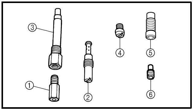
2. Inspect:
- Main jet ①
- Pilot jet ②
- Needle jet ③
- Starter jet ④
- Pilot air jet ⑤
- Leak jet ⑥
Damage → Replace.
Contamination → Clean.
NOTE:
- Use a petroleum based solvent for cleaning. Blow out all passages and jets with compressed air.
- Never use a wire.
REMARQUES CONCERNANT LA MANIPULATION
ATTENTION:
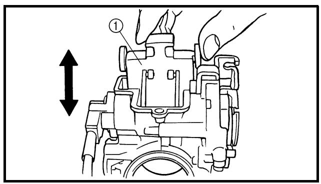
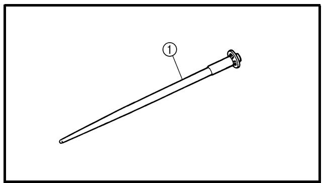
natural_image
Line drawing of a mechanical tool with a labeled component (1), no text or symbols present
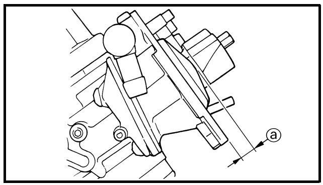
natural_image
Technical line drawing of a mechanical assembly with no visible text or symbols
Needle valve
1. Inspect:
- Needle valve ①
- Valve seat ②
Grooved wear ⓐ → Replace.
Dust ⓑ → Clean.
- Filter ©
Clogged → Clean.
EC464300
Throttle valve
1. Check:
- Free movement
Stick → Repair or replace.
NOTE:
Insert the throttle valve ① into the carburetor body, and check for free movement.
EC464400
Jet needle
1. Inspect:
- Jet needle ①
Bends/wear → Replace.
- Clip groove
Free play exists/wear → Replace.
EC464511
Float height
1. Measure:
- Float height ⓐ
Out of specification → Adjust.

Float height: 8.0 mm (0.31 in)
Pointeau
natural_image
Technical line drawing of a mechanical device with two components and a labeled part (b), no text or symbols present.
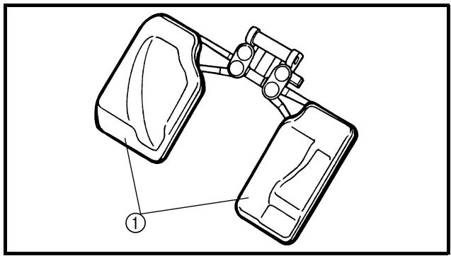
natural_image
Technical line drawing of a mechanical device with two components and a labeled connection point (no text or symbols present)
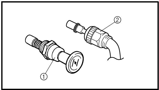
Measurement and adjustment steps:
- Hold the carburetor in an upside down position.
NOTE:
- Slowly tilt the carburetor in the opposite direction, then take the measurement when the needle valve aligns with the float arm.
- If the carburetor is level, the weight of the float will push in the needle valve, resulting in an incorrect measurement.
- Measure the distance between the mating surface of the float chamber and top of the float using a vernier calipers.
NOTE:
The float arm should be resting on the needle valve, but not compressing the needle valve.
- If the float height is not within specification, inspect the valve seat and needle valve.
- If either is worn, replace them both.
- If both are fine, adjust the float height by bending the float tab ⑥ on the float.
- Recheck the float height.
EC464600
Float
- Inspect:
- Float ①
Damage → Replace.
Starter plunger
-
Inspect:
-
Cold starter plunger ①
- Hot starter plunger ②
Wear/damage → Replace.
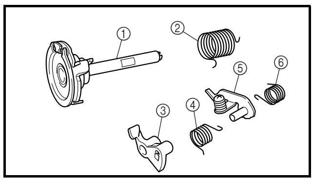
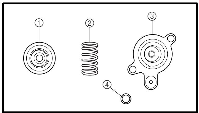
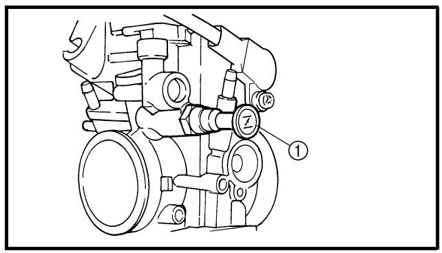
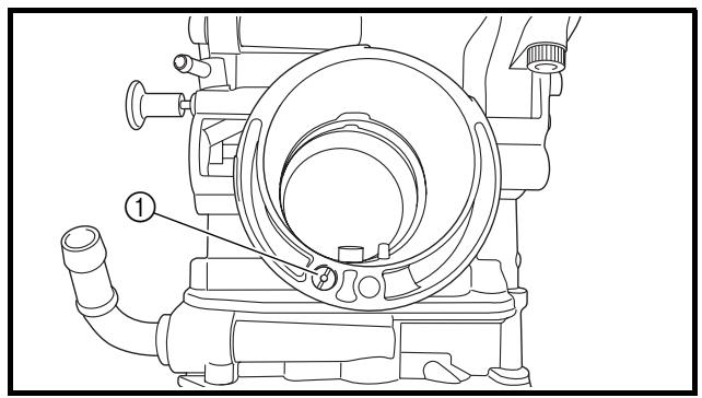
natural_image
Technical line drawing of a mechanical component with labeled parts (no text or symbols present)
Accelerator pump
1. Inspect:
• Diaphragm (accelerator pump) ①
- Spring ②
- Cover ③
- O-ring ④
- Push rod ⑤
Tears (diaphragm)/damage → Replace.
Dirt → Clean.
2. Inspect:
- Throttle shaft ①
- Spring ②
- Lever 1 ③
- Spring 1 ④
- Lever 2 ⑤
- Spring 2 ⑥
Dirt → Clean.
Air cut valve
1. Inspect:
• Diaphragm (air cut valve) ①
- Spring (air cut valve) ②
- Air cut valve cover ③
- O-ring ④
Tears (diaphragm)/damage → Replace.
ASSEMBLY AND INSTALLATION Carburetor
1. Install:
- Cold starter plunger ①
2. Install:
- Pilot air jet ①
Pompe de reprise
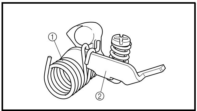
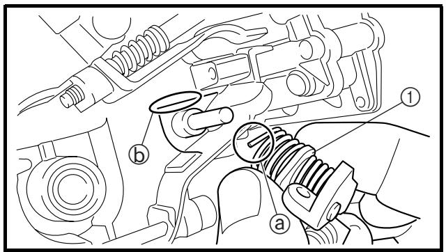
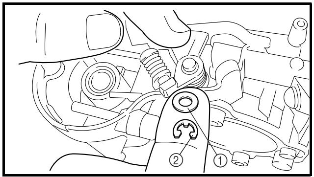
natural_image
Technical line drawing of a mechanical assembly with labeled parts (no text or symbols present)
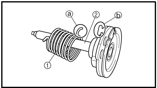
3. Install:
To lever 2 ③.
NOTE: \_\_\_\_
Make sure the spring 1 fits on the stopper ⓐ of the lever 2.
4. Install:
- Spring 2 ①
To lever 2 ②.
5. Install:
- Push rod link lever assembly ①
NOTE:
Make sure the stopper ⓐ of the spring 2 fits into the recess ⓑ in the carburetor.
6. Install:
7. Install:
- Spring ①
To throttle shaft ②.
NOTE:
Install the bigger hook ⓐ of the spring fits on the stopper Ⓑ of the throttle shaft pulley.
- Monter:
- Ressort 1 ①
- Levier 1 ②
Sur le levier 2 ③.
N.B.:
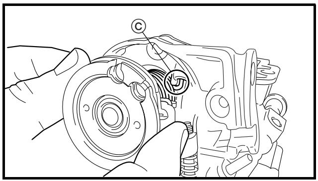
natural_image
Technical line drawing of a mechanical assembly with no visible text or symbols
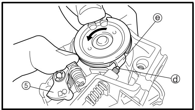
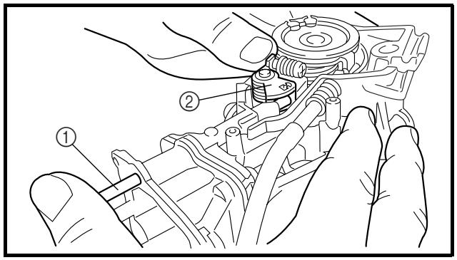
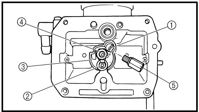
8. Install:
- Throttle shaft assembly ①
- Plain washer (metal) ②
- Plain washer (resin) ③
- Valve lever ④
NOTE:
- Apply the fluorochemical grease on the bearings.
- Fit the projection ⓐ on the throttle shaft assembly into the slot ⓑ in the TPS (throttle position sensor).
- Make sure the stopper © of the spring fits into the recess in the carburetor.
- Turn the throttle shaft assembly left while holding down the lever 1 ⑤ and fit the throttle stop screw tip ⓑ to the stopper Ⓔ of the throttle shaft assembly pulley.
9. Install:
- Push rod ①
NOTE:
While holding down the lever 1 ②, insert the push rod farthest into the carburetor.
10. Install:
- Starter jet ①
- Pilot jet ②
- Spacer ③
- Needle jet ④
- Main jet ⑤
8. Monter:
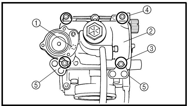
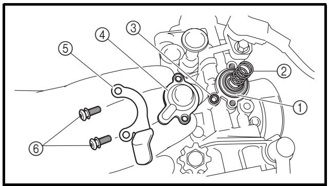
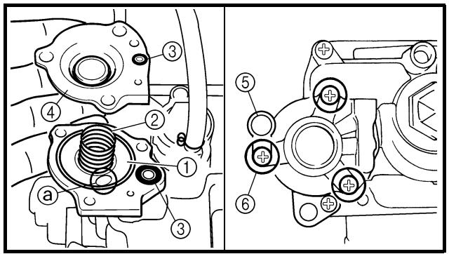
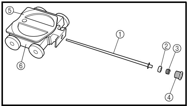
11. Install:
- Needle valve ①
- Float ②
- Float pin ③
NOTE:
- After installing the needle valve to the float, install them to the carburetor.
- Check the float for smooth movement.
12. Install:
- O-ring
- Leak jet ①
- Float chamber ②
- Bolt (float chamber) ③
- Cable holder (throttle stop screw cable)
④
- Hose holder (carburetor breather hose)
⑤
13. Install:
- Diaphragm (air cut valve) ①
- Spring (air cut valve) ②
- O-ring ③
- Air cut valve cover ④
- Holder (cylinder head breather hose) ⑤
- Screw (air cut valve cover) ⑥
14. Install:
- Diaphragm (accelerator pump) ①
- Spring ②
- O-ring ③
- Cover ④
- Hose holder (drain hose) ⑤
- Screw (cover) ⑥
NOTE:
Install the diaphragm (accelerator pump) with its mark ⓐ facing the spring.
15. Install:
- Jet needle ①
- Collar ②
- Spring ③
- Needle holder ④
- Throttle valve plate ⑤
To throttle valve ⑥.
11. Monter:
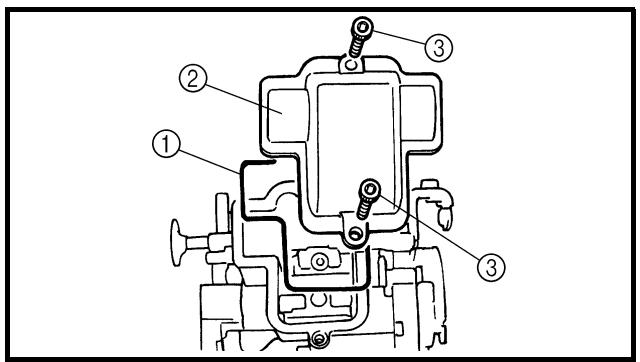
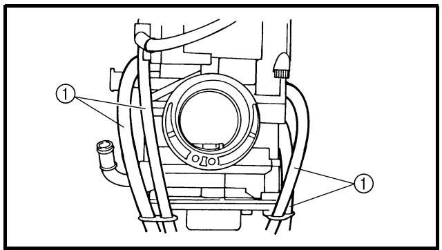
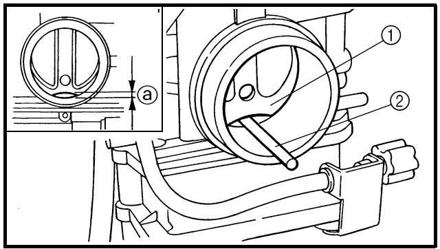
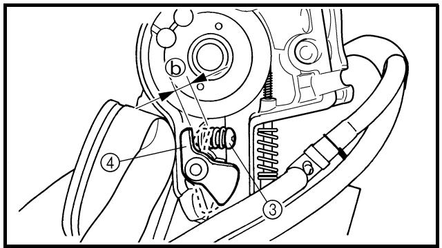
16. Install:
- Throttle valve assembly ①
- Screw (throttle shaft) ②
NOTE:
Install the valve lever rollers ③ into the slits ④ of the throttle valve.
17. Install:
- O-ring ①
- Valve lever housing cover ②
- Bolt (valve lever housing cover) ③
18. Install:
- Carburetor breather hose ①
Refer to “CABLE ROUTING DIAGRAM” section in the CHAPTER 2.
Accelerator pump timing adjustment
Adjustment steps:
NOTE:
In order for the throttle valve height ⓐ to achieve the specified value, tuck under the throttle valve plate ① the rod ② etc. with the same outer diameter as the specified value.

Throttle valve height: 3.1 mm (0.122 in)
- Fully turn in the accelerator pump adjusting screw ③.
- Check that the link lever ④ has free play ⑥ by pushing lightly on it.
- Gradually turn out the adjusting screw while moving the link lever until it has no more free play.
16. Monter:
- Papillon complet ①
Carburetor installation
1. Install:
- Carburetor joint ①
- Bracket (cylinder head breather pipe) ②
- Bolt (carburetor joint) ③
10 Nm (1.0 m · kg, 7.2 ft · lb)
- Cylinder head breather pipe ④
- Cylinder head breather hose 1 ⑤
- Cylinder head breather hose 2 ⑥
- Cylinder head breather hose 3 ⑦
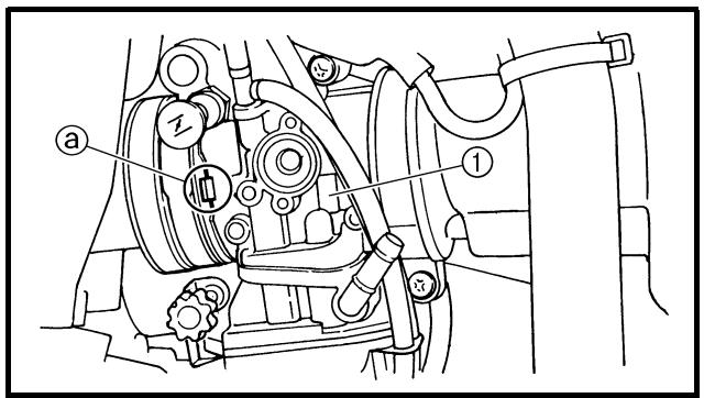
2. Install:
- Carburetor ①
NOTE:
Install the projection ⓐ between the carburetor joint slots.
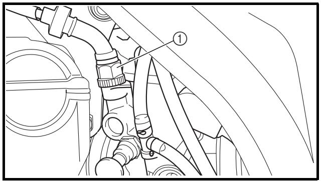
natural_image
Technical line drawing of a mechanical assembly with pipes and valves (no text or symbols)
3. Install:
- Hot starter plunger ①
2 Nm (0.2 m · kg, 1.4 ft · lb)
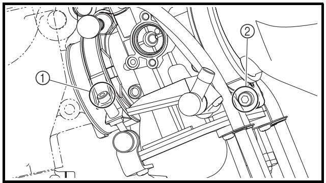
4. Tighten:
- Bolt (carburetor joint) ①
3 Nm (0.3 m · kg, 2.2 ft · lb)
- Bolt (air cleaner joint) ②
3 Nm (0.3 m · kg, 2.2 ft · lb)
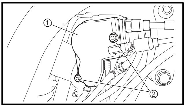
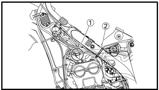
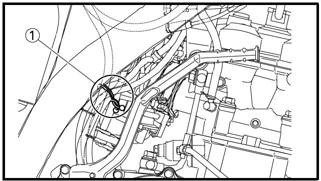
5. Install:
- Throttle cable (return) ②
11 Nm (1.1 m · kg, 8.0 ft · lb)
6. Adjust:
- Throttle grip free play
Refer to "THROTTLE CABLE ADJUSTMENT" section in the CHAPTER 3.
7. Install:
- Throttle cable cover ①
- Bolt (throttle cable cover) ②
4 Nm (0.4 m · kg, 2.9 ft · lb)
8. Install:
- TPS (throttle position sensor) coupler ①
- Clamp ②
Refer to "CABLE ROUTING DIAGRAM" section in the CHAPTER 2.
9. Install:
- Clamp ①
Refer to "CABLE ROUTING DIAGRAM" section in the CHAPTER 2.
5. Monter:
Extent of removal:
① Air induction system removal
| Extent of removal | Order | Part name | Q'ty | Remarks |
| | AIR INDUCTION SYSTEM REMOVAL | | |
| 1 | Bracket | 1 | |
| 2 | Air cut-off valve assembly | 1 | |
| 3 | Air induction hose (air cut-off valve - front of cylinder head) | 1 | |
| 4 | Air induction pipe | 1 | |
| 5 | Gasket | 1 | |
| 6 | Air induction hose (air cut-off valve - rear of cylinder head) | 1 | |
| 7 | Air induction hose (air cut-off valve - air filter case) | 1 | |
SYSTEME D'INDUCTION D'AIR

Air induction system
1. Inspect:
• Air induction hose
Crack/damage → Replace.
- Air induction pipe
Crack/damage → Replace.
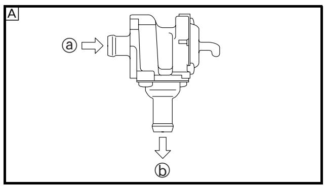
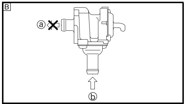
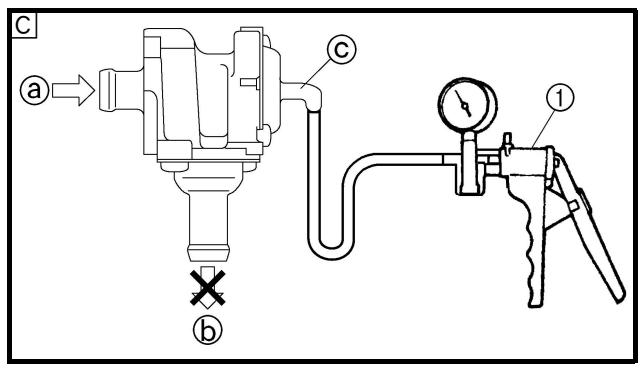
2. Check:
- Operation of air cut valve
Pass air through the pipe and check the air cut valve for operation.
Does not meet the following condition → Replace the air cut valve assembly.
| a to b | Air passes. |
| b to a | Air does not pass. |
| a to b | Air does not pass when specified pressure is on ©. |
NOTE:
- Blow in air to check for operation.
- When using vacuum, check by the use of the vacuum/pressure pump gauge set ①.
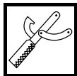
Vacuum/pressure pump gauge set:
YB-35956-A/90890-06756

Vacuum specifying pressure:
46.7 \~ 86.7 kPa
(350 \~ 650 mmHg,
13.8 \~ 25.6 inHg)
CAUTION:
When using vacuum on the pipe Ⓒ, take care not to exceed the specified value.
① From air filter
⑥ To cylinder head (exhaust port)
© From cylinder head (intake port)
A Check for induction from air filter.
B Check for prevention of backflow into air filter.
☐ Check for prevention of afterburn.
(When throttle is closed at sudden deceleration)
CONTROLE
Extent of removal:
① Cylinder head cover removal
| Extent of removal | Order | Part name | Q'ty | Remarks |
| Preparation for removal | | CYLINDER HEAD COVER REMOVALSeat and fuel tankAir cut-off valve assemblyEngine upper bracket (right)Engine upper bracket (left) | | Refer to “SEAT, FUEL TANK AND SIDE COVERS” section.Refer to “AIR INDUCTION SYSTEM” section.Refer to “ENGINE REMOVAL” section. |
| (bearful) | 1 | Spark plug | 1 | |
| 2 | Cylinder head breather hose | 1 |
| 3 | Bolt (cylinder head cover) | 2 |
| 4 | Cylinder head cover | 1 |
| 5 | Cylinder head cover gasket | 1 |
ARBRES A CAMES
COUVRE-CULASSE
Extent of removal:
① Camshaft removal
| Extent of removal | Order | Part name | Q'ty | Remarks |
| | CAMSHAFTS REMOVAL | | |
| 1 | Timing plug | 1 | Refer to “REMOVAL POINTS”. |
| 2 | Straight plug | 1 |
| 3 | Tensioner cap bolt | 1 |
| 4 | Timing chain tensioner | 1 |
| 5 | Gasket | 1 |
| 6 | Bolt (camshaft cap) | 10 |
| 7 | Camshaft cap | 2 |
| 8 | Clip | 2 |
| 9 | Exhaust camshaft | 1 |
| 10 | Intake camshaft | 1 |
ARBRES A CAMES
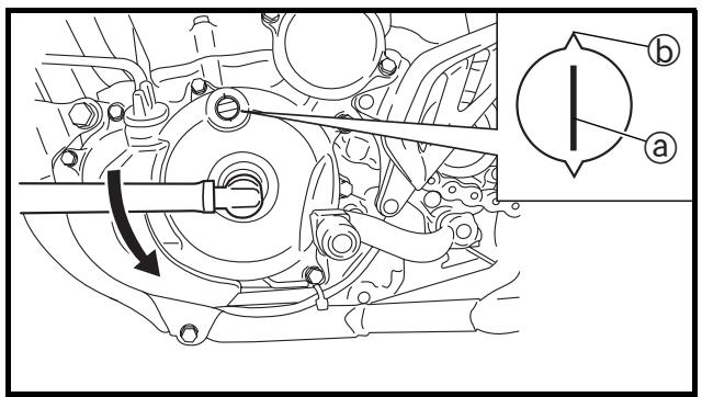
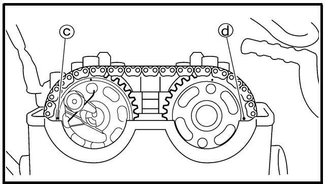
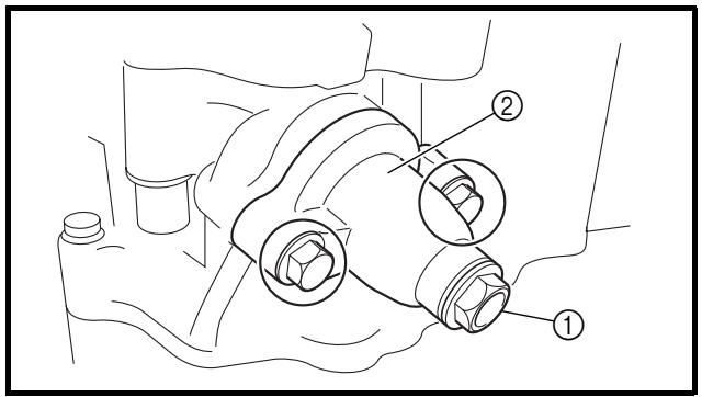
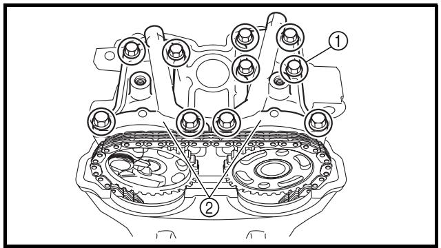
REMOVAL POINTS Camshaft
1. Remove:
- Timing plug ①
- Straight plug ②
2. Align:
- "l" mark
With stationary pointer.
Checking steps:
- Turn the crankshaft counterclockwise with a wrench.
- Align the “l” mark ⓐ on the rotor with the stationary pointer ⓑ on the crankcase cover. When the “l” mark is aligned with the stationary pointer, the piston is at the Top Dead Center (T.D.C.).
NOTE:
- In order to be sure that the piston is at Top Dead Center, the punch mark © on the exhaust camshaft and the punch mark ⓐ on the intake camshaft must align with the cylinder head surface, as shown in the illustration.
- If there is no clearance, rotate the crankshaft counterclockwise one turn.
3. Loosen:
- Tensioner cap bolt ①
4. Remove:
- Timing chain tensioner ②
5. Remove:
- Bolt (camshaft cap) ①
- Camshaft caps ②
NOTE:
Remove the bolts (camshaft cap) in a criss-cross pattern, working from the outside in.
CAUTION:
The bolts (camshaft cap) must be removed evenly to prevent damage to the cylinder head, camshafts or camshaft caps.
POINTS DE DEPOSE
Arbre à cames
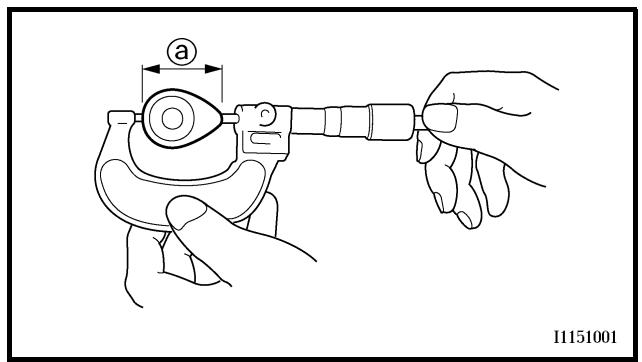
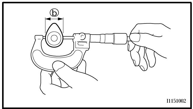
6. Remove:
- Clips
- Exhaust camshaft ①
- Intake camshaft ②
NOTE:
Attach a wire ③ to the timing chain to prevent it from falling into the crankcase.
INSPECTION
Camshaft
1. Inspect:
- Cam lobes
Pitting/scratches/blue discoloration → Replace.
2. Measure:
- Cam lobes length ⓐ and ⓑ
Out of specification → Replace.

Cam lobes length:
Intake:
① 30.100 \~ 30.200 mm
(1.1850 \~ 1.1890 in)
: 30.000 mm
(1.1811 in)
⑥ 22.450 \~ 22.550 mm
(0.8839 \~ 0.8878 in)
: 22.350 mm
(0.8799 in)
Exhaust:
① 30.200 \~ 30.300 mm
(1.1890 \~ 1.1929 in)
: 30.100 mm
(1.1850 in)
⑥ 22.450 \~ 22.550 mm
(0.8839 \~ 0.8878 in)
: 22.350 mm
(0.8799 in)
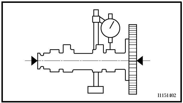
3. Measure:
- Runout (camshaft)
Out of specification → Replace.

Runout (camshaft):
Less than 0.03 mm (0.0012 in)
① 30,100–30,200 mm (1,1850–1,1890 in)
:
30,000 mm (1,1811 in)
⑥ 22,450–22,550 mm (0,8839–0,8878 in)
:
22,350 mm (0,8799 in)
Auslass:
① 30,200–30,300 mm (1,1890–1,1929 in)
:
30,100 mm (1,1850 in)
⑥ 22,450–22,550 mm (0,8839–0,8878 in)
:
22,350 mm (0,8799 in)

① 30,100 \~ 30,200 mm
(1,1850 \~ 1,1890 in)
:
30,000 mm
(1,1811 in)
⑥ 22,450 \~ 22,550 mm
(0,8839 \~ 0,8878 in)
:
22,350 mm
(0,8799 in)
Escape:
① 30,200 \~ 30,300 mm
(1,1890 \~ 1,1929 in)
:
30,100 mm
(1,1850 in)
⑥ 22,450 \~ 22,550 mm
(0,8839 \~ 0,8878 in)
:
22,350 mm
(0,8799 in)
- Mesurer:
- Camshaft-to-cap clearance
Out of specification → Measure camshaft journal diameter.

Camshaft-to-cap clearance:
0.028 \~ 0.062 mm
(0.0011 \~ 0.0024 in)
: 0.08 mm (0.003 in)
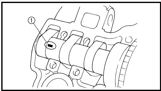
Measurement steps:
- Install the camshaft onto the cylinder head.
- Position a strip of Plastigauge® ① onto the camshaft.
- Install the circlip, dowel pins and camshaft caps.

Bolt (camshaft cap):
10 Nm (1.0 m • kg, 7.2 ft • lb)
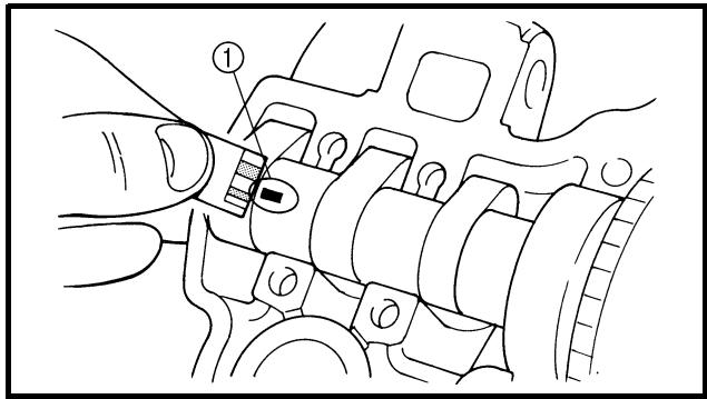
NOTE:
- Tighten the bolts (camshaft cap) in a criss-cross pattern from innermost to outer caps.
- Do not turn the camshaft when measuring clearance with the Plastigauge®.
- Remove the camshaft caps and measure the width of the Plastigauge® ①.
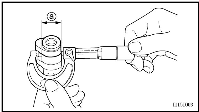
5. Measure:
- Camshaft journal diameter ⓐ
Out of specification → Replace the camshaft.
Within specification → Replace camshaft case and camshaft caps as a set.

Camshaft journal diameter:
21.959 \~ 21.972 mm
(0.8645 \~ 0.8650 in)
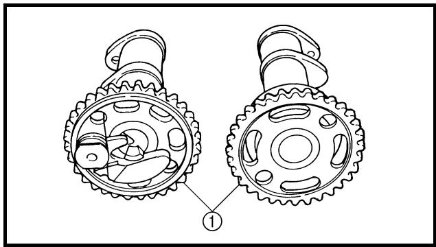
natural_image
Technical line drawing of two mechanical gears with internal components, no text or symbols present
Camshaft sprocket
1. Inspect:
- Camshaft sprocket ①
Wear/damage → Replace the camshaft assembly and timing chain as a set.
4. Mesurer:
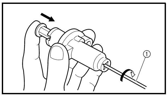
natural_image
Illustration of a hand holding a mechanical component with a tool, showing a curved arrow and numbered label (no text or symbols present)
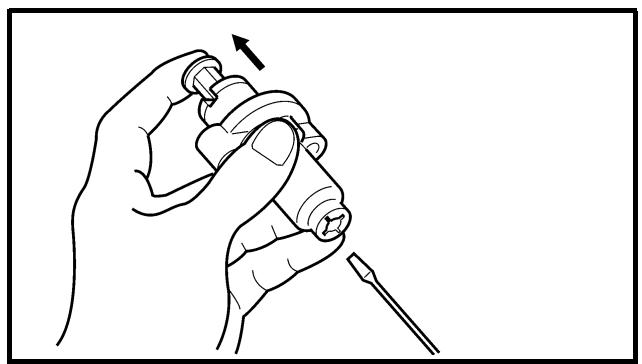
natural_image
Line drawing of a hand holding a small object with an arrow indicating motion (no text or symbols)
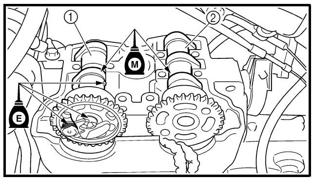
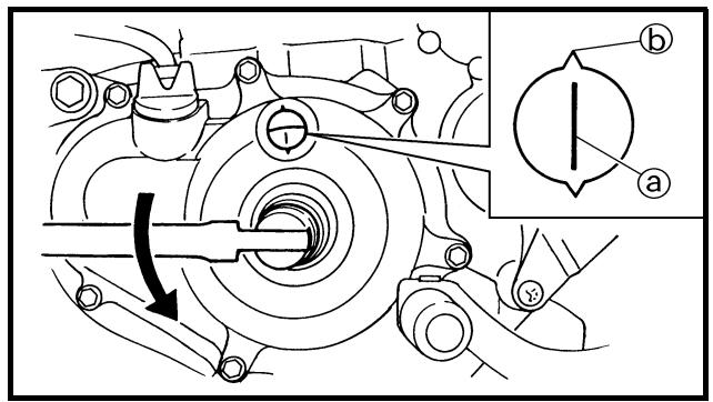
Decompression system
1. Check:
- Decompression system
Checking steps:
- Check that the decompressor cam ① moves smoothly.
- Check that the decompressor lever pin ② projects from the camshaft.
Timing chain tensioner
1. Check:
- While pressing the tensioner rod lightly with fingers, use a thin screwdriver ① and wind the tensioner rod up fully clockwise.
- When releasing the screwdriver by pressing lightly with fingers, make sure that the tensioner rod will come out smoothly.
- If not, replace the tensioner assembly.
ASSEMBLY AND INSTALLATION
1. Install:
- Exhaust camshaft ①
- Intake camshaft ②
Installation steps:
- Turn the crankshaft counterclockwise until the “l” mark ⓐ on the rotor is aligned with the stationary pointer ⓑ on the crankcase cover.
NOTE:
- Apply the molybdenum disulfide oil on the camshafts.
- Apply the engine oil on the decompression system.
Décompresseur
- Contrôler:
- Décompresseur
Etapes du contrôle:
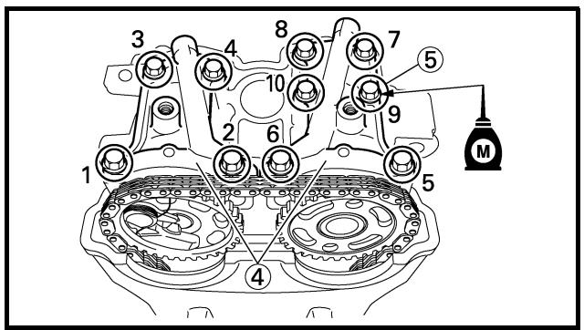
- Fit the timing chain ③ onto both camshaft sprockets and install the camshafts on the cylinder head.
NOTE:
The camshafts should be installed onto the cylinder head so that the exhaust cam sprocket punch mark © and the intake cam sprocket punch mark ⓐ align with the surface of the cylinder head.
CAUTION:
Do not turn the crankshaft during the camshaft installation. Damage or improper valve timing will result.
• Install the clips and camshaft caps ④.

Bolt (camshaft cap):
10 Nm (1.0 m • kg, 7.2 ft • lb)
NOTE:
- Apply the molybdenum disulfide oil on the thread of the bolts (camshaft cap) ⑤.
- Tighten the bolts to the specified torque in two or three steps in the proper tightening sequence as shown.
CAUTION:
The bolts (camshaft cap) must be tightened evenly, or damage to the cylinder head, camshaft caps, and camshaft will result.
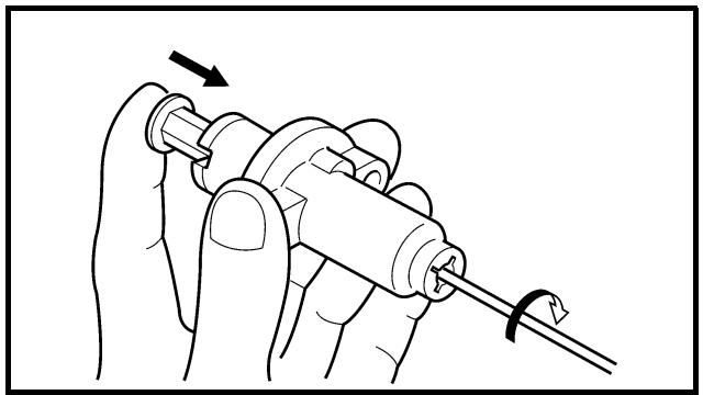
natural_image
Illustration of a hand holding a mechanical component with a curved arrow indicating rotation (no text or symbols)
2. Install:
- Timing chain tensioner
Installation steps:
- While pressing the tensioner rod lightly with fingers, use a thin screwdriver and wind the tensioner rod up fully clockwise.
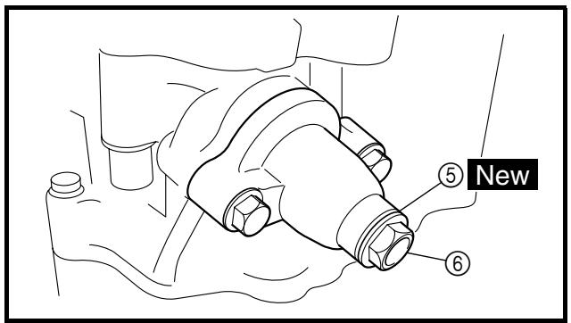
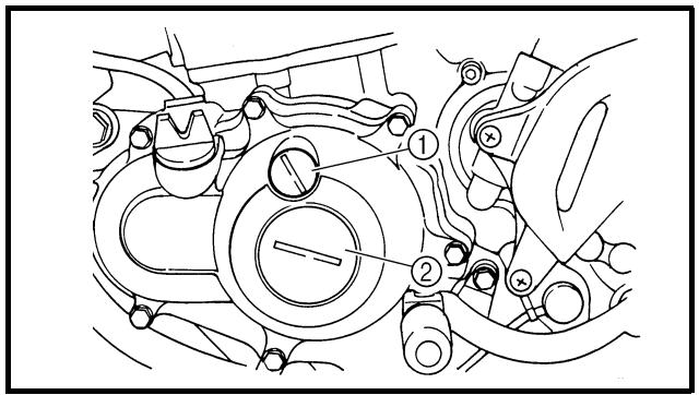
- With the rod fully wound and the chain tensioner UP mark ⓐ facing upward, install the gasket ①, the chain tensioner ② and the gasket ③ and tighten the bolt ④ to the specified torque.
Bolt (timing chain tensioner): 10 Nm (1.0 m • kg, 7.2 ft • lb)
- Release the screwdriver, check the tensioner rod to come out and tighten the gasket ⑤ and the cap bolt ⑥ to the specified torque.

Tensioner cap bolt:
7 Nm (0.7 m • kg, 5.1 ft • lb)
3. Turn:
- Crankshaft
Counterclockwise several turns
4. Check:
- Rotor "I" mark
Align with the crankcase stationary pointer.
- Camshaft match marks
Align with the cylinder head surface.
Out of alignment → Adjust.
5. Install:
- Timing plug ①
- Straight plug ②
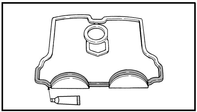
natural_image
Technical line drawing of a mechanical component with no visible text or symbols
6. Install:
- Cylinder head cover gasket ①
- Cylinder head cover ②
- Bolt (cylinder head cover) ③
10 Nm (1.0 m · kg, 7.2 ft · lb)
NOTE:
Apply the sealant on the cylinder head cover gasket.
YAMAHA Bond No. 1215
(ThreeBond® No. 1215):
90890-85505
7. Install:
- Cylinder head breather hose
- Spark plug
13 Nm (1.3 m · kg, 9.4 ft · lb)
6. Monter:
• Joint de couvre-culasse ①
- Couvre-culasse ②
• Boulon (couvre-culasse) ③
10 Nm (1,0 m · kg, 7,2 ft · lb)
N.B.:
Extent of removal:
① Cylinder head removal
| Extent of removal | Order | Part name | Q'ty | Remarks |
| Preparation for removal | | CYLINDER HEAD REMOVALSeat and fuel tankExhaust pipe and silencerRadiatorAir cut-off valve assemblyCarburetorCamshaft | | Refer to “SEAT, FUEL TANK AND SIDE COVERS” section.Refer to “EXHAUST PIPE AND SILENCER” section.Refer to “RADIATOR” section.Refer to “AIR INDUCTION SYSTEM” section.Refer to “CARBURETOR” section.Refer to “CAMSHAFTS” section. |
| [72X48] | 1 | Bolt | 2 | Refer to NOTE. |
| 2* | Bolt | 4 |
| 3 | Cylinder head | 1 |
| 4 | Gasket | 1 |
| 5 | Dowel pin | 2 |
| 6 | Timing chain guide (front) | 1 |
NOTE:
Tighten the cylinder head bolts to 30 Nm (3.0 m • kg, 22 ft • lb) in the proper tightening sequence, remove and retighten the cylinder head bolts to 20 Nm (2.0 m • kg, 14 ft • lb) in the proper tightening sequence, and then tighten the cylinder head bolts further to reach the specified angle 180^ in the proper tightening sequence.
CULASSE
CULASSE

natural_image
Technical line drawing of an internal combustion engine cylinder with a tool inserted (no text or labels)
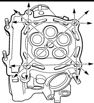
natural_image
Technical line drawing of an internal combustion engine cylinder (no text or labels)
INSPECTION
Cylinder head
1. Eliminate:
- Carbon deposits (from the combustion chambers)
Use a rounded scraper.
NOTE:
Do not use a sharp instrument to avoid damaging or scratching:
- Spark plug threads
- Valve seats
2. Inspect:
- Cylinder head
Scratches/damage → Replace.
3. Measure:
- Cylinder head warpage
Out of specification → Resurface.
Cylinder head warpage: Less than 0.05 mm (0.002 in)
Warpage measurement and resurface-ment steps:
- Place a straightedge and a feeler gauge across the cylinder head.
- Use a feeler gauge to measure the warpage.
- If the warpage is out of specification, resurface the cylinder head.
- Place a 400 \~ 600 grit wet sandpaper on the surface plate, and resurface the head using a figure-eight sanding pattern.
NOTE:
To ensure an even surface rotate the cylinder head several times.
CONTROLE
Culasse
1. Eliminer:
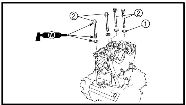
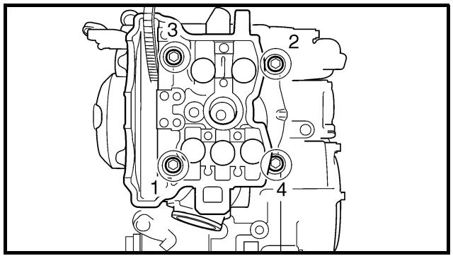
ASSEMBLY AND INSTALLATION
1. Install:
- Timing chain guide (front) ①
- Dowel pin ②
- Cylinder head gasket ③ New
- Cylinder head ④
NOTE:
While pulling up the timing chain, install the timing chain guide (front) and cylinder head.
2. Install:
Installation steps:
CAUTION:
Tighten the cylinder head using the rotation angle procedure to obtain uniform tightening torque.
- Wash the threads and contact surfaces of the bolts, the contact surfaces of the plain washers, the contact surface of the cylinder head, and the threads of the crank-case.
- Apply the molybdenum disulfide grease on the threads and contact surfaces of the bolts and on both contact surfaces of the plain washers.
• Install the plain washers and bolts.
- Tighten the bolts to the specified torque in two or three steps in the proper tightening sequence as shown.
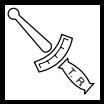
Bolts (cylinder head):
1st:
30 Nm (3.0 m • kg, 22 ft • lb)
ASSEMBLAGE ET MONTAGE
1. Monter:
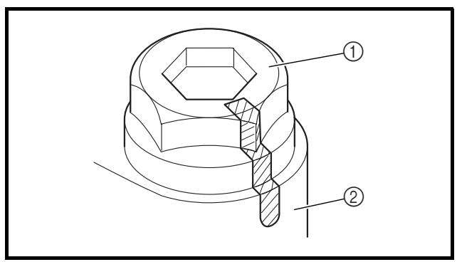
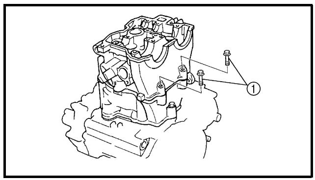
- Remove the bolts.
- Again apply the molybdenum disulfide grease on the threads and contact surfaces of the bolts and on both contact surfaces of the plain washers.
- Retighten the bolts.
NOTE:
Tighten the bolts to the specified torque in two or three steps in the proper tightening sequence as shown.
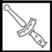
Bolts (cylinder head):
2nd:
20 Nm (2.0 m • kg, 14 ft • lb)
- Put a mark on the corner ① of the bolt (cylinder head) and the cylinder head ② as shown.
NOTE:
Tighten the bolts 90^ in each of the two steps to reach the specified angle of 180^ in the proper tightening sequence as shown.
Bolts (cylinder head):
Final:
Specified angle 180°
3. Install:
- Bolt (cylinder head) ①

10 Nm (1.0 m · kg, 7.2 ft · lb)
Boulons (culasse): Final:
Extent of removal:
① Valve removal
| Extent of removal | Order | Part name | Q'ty | Remarks |
| Preparation for removal | | VALVES AND VALVE SPRINGS REMOVALCylinder head | | Refer to “CYLINDER HEAD” section. |
| 1 | 1 | Valve lifter | 5 | Use special tool.Refer to “REMOVAL POINTS”. |
| 2 | Adjusting pad | 5 |
| 3 | Valve cotter | 10 |
| 4 | Valve retainer | 5 |
| 5 | Valve spring | 5 |
| 6 | Stem seal | 5 |
| 7 | Valve spring seat | 5 |
| 8 | Exhaust valve | 2 |
| 9 | Intake valve | 3 |
SOUPAPES ET RESSORTS DE SOUPAPES SOUPAPES ET RESSORTS DE SOUPAPES
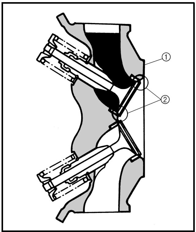
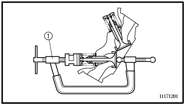
REMOVAL POINTS
Valve lifter and valve cotter
1. Remove:
NOTE:
Identify each lifter ① and pad ② position very carefully so that they can be reinstalled in their original place.
2. Check:
- Valve sealing
Leakage at the valve seat → Inspect the valve face, valve seat and valve seat width.
Checking steps:
- Pour a clean solvent ① into the intake and exhaust ports.
- Check that the valve seals properly.
There should be no leakage at the valve seat ②.
3. Remove:
- Valve cotters
NOTE:
Attach a valve spring compressor ① between the valve spring retainer and the cylinder head to remove the valve cotters.
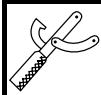
Valve spring compressor: YM-4019/90890-04019
POINTS DE DEPOSE
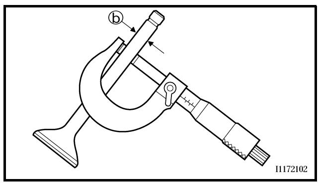
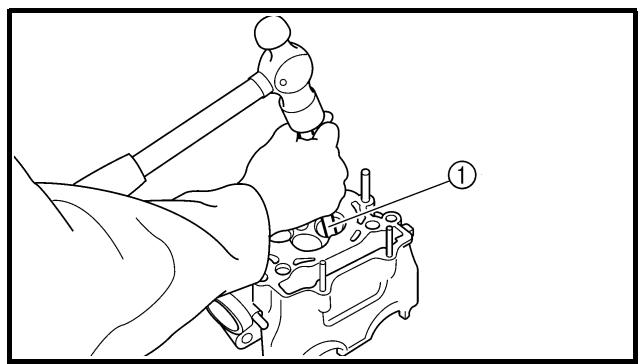
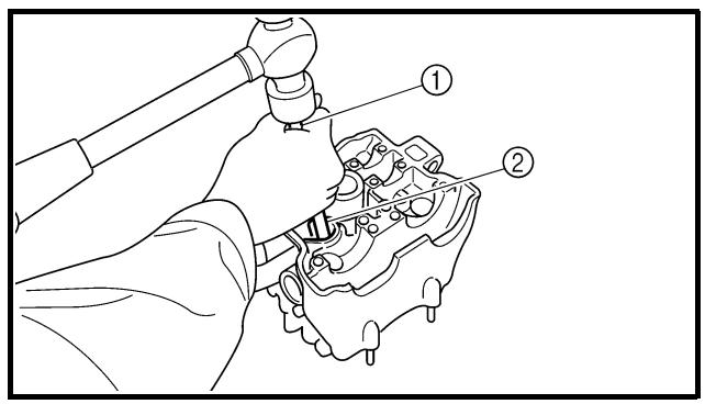
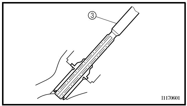
INSPECTION
Valve
1. Measure:
- Stem-to-guide clearance
Stem-to-guide clearance = valve guide inside diameter ① - valve stem diameter ②
Out of specification → Replace the valve guide.

Clearance (stem to guide):
Intake:
0.010 \~ 0.037 mm
(0.0004 \~ 0.0015 in)
: 0.08 mm (0.003 in)
Exhaust:
0.020 \~ 0.047 mm
(0.0008 \~ 0.0019 in)
: 0.10 mm (0.004 in)
2. Replace:
- Valve guide
Replacement steps:
NOTE:
To ease guide removal, installation and to maintain correct fit heat the cylinder head in an over to 100 °C ( 212 °F ).
- Remove the valve guide using a valve guide remover ①.
- Install the new valve guide using a valve guide remover ① and valve guide installer ②.
- After installing the valve guide, bore the valve guide using a valve guide reamer ③ to obtain proper stem-to-guide clearance.
CONTROLE
Soupape
- Mesurer:
- Jeu queue-guide
Intake: 4.5 mm (0.18 in)
YM-4116/90890-04116
Exhaust: 5.0 mm (0.20 in)
YM-4097/90890-04097
Valve guide installer:
Intake:
YM-4117/90890-04117
Exhaust:
YM-4098/90890-04098
Valve guide reamer:
Intake: 4.5 mm (0.18 in)
YM-4118/90890-04118
Exhaust: 5.0 mm (0.20 in)
YM-4099/90890-04099
NOTE:
After replacing the valve guide reface the valve seat.
3. Inspect:
- Valve face
Pitting/wear → Grind the face.
- Valve stem end
Mushroom shape or diameter larger than the body of the stem → Replace.
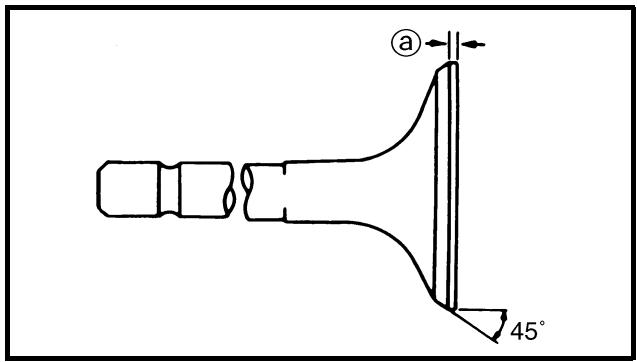
4. Measure:
- Margin thickness ⓐ
Out of specification → Replace.

Margin thickness:
Intake:
1.0 mm (0.039 in)
: 0.85 mm (0.033 in)
Exhaust:
1.0 mm (0.039 in)
: 0.85 mm (0.033 in)

natural_image
Technical diagram of a mechanical device with a dial indicator and rotating shaft (no text or symbols)
5. Measure:
Out of specification → Replace.

Runout limit: 0.01 mm (0.0004 in)
NOTE:
- When installing a new valve always replace the guide.
- If the valve is removed or replaced always replace the oil seal.
6. Eliminate:
- Carbon deposits
(from the valve face and valve seat)
7. Inspect:
- Valve seats
Pitting/wear → Reface the valve seat.
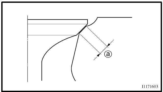
8. Measure:
- Valve seat width ⓐ
Out of specification → Reface the valve seat.
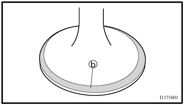
natural_image
Diagram of a circular object with a labeled point 'b' and a vertical line, no readable text or symbols present.

Valve seat width:
Intake:
0.9 \~ 1.1 mm
(0.0354 \~ 0.0433 in)
: 1.6 mm (0.0630 in)
Exhaust:
0.9 \~ 1.1 mm
(0.0354 \~ 0.0433 in)
: 1.6 mm (0.0630 in)
Measurement steps:
- Apply Mechanic's blueing dye (Dykem) ⑥ to the valve face.
• Install the valve into the cylinder head.
- Press the valve through the valve guide and onto the valve seat to make a clear pattern.
- Measure the valve seat width. Where the valve seat and valve face made contact, blueing will have been removed.
- If the valve seat is too wide, too narrow, or the seat is not centered, the valve seat must be refaced.
5. Mesurer:
After refacing the valve seat or replacing the valve and valve guide, the valve seat and valve face should be lapped.
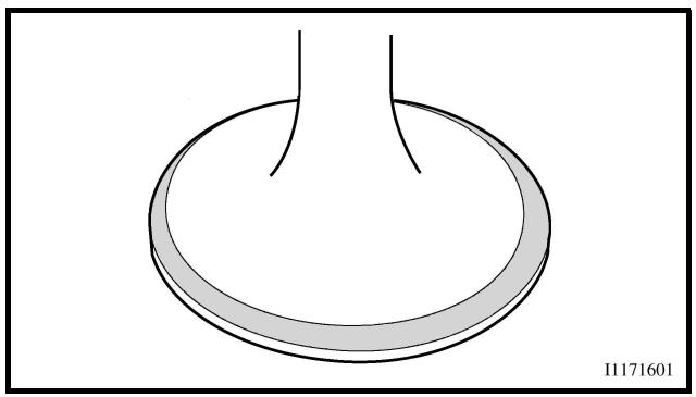
natural_image
Simple line drawing of a circular object with two vertical lines extending outward (no text or symbols)
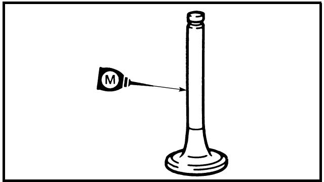
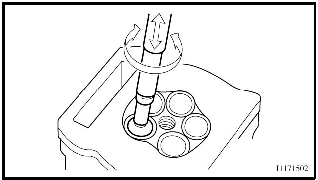
natural_image
Technical line drawing of a mechanical assembly with rotating components and a central shaft (no text or symbols)
Lapping steps:
- Apply a coarse lapping compound to the valve face.
CAUTION:
Do not let the compound enter the gap between the valve stem and the guide.
- Apply molybdenum disulfide oil to the valve stem.
• Install the valve into the cylinder head.
- Turn the valve until the valve face and valve seat are evenly polished, then clean off all of the compound.
NOTE:
For best lapping results, lightly tap the valve seat while rotating the valve back and forth between your hands.
- Apply a fine lapping compound to the valve face and repeat the above steps.
NOTE:
After every lapping operation be sure to clean off all of the compound from the valve face and valve seat.
- Apply Mechanic's blueing dye (Dykem) to the valve face.
• Install the valve into the cylinder head.
- Press the valve through the valve guide and onto the valve seat to make a clear pattern.
- Measure the valve seat width again. If the valve seat width is out of specification, reface and relap the valve seat.
SOUPAPES ET RESSORTS DE SOUPAPES VENTILE UND VENTILFEDERN VÁLVULAS Y MUELLES DE VÁLVULAS
ENG

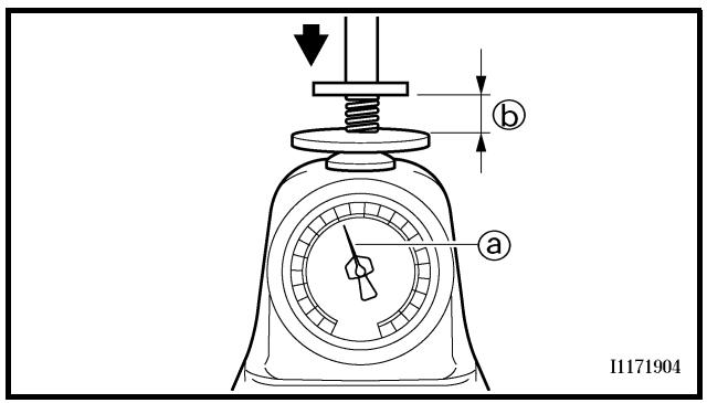
Valve spring
1. Measure:
- Valve spring free length ⓐ
Out of specification → Replace.

Free length (valve spring):
Intake:
39.46 mm (1.55 in)
: 38.46 mm (1.51 in)
Exhaust:
37.61 mm (1.48 in)
: 36.61 mm (1.44 in)
2. Measure:
- Compressed spring force ⓐ
Out of specification → Replace.
⑥ Installed length

Compressed spring force:
Intake:
130.2 \~ 149.8 N at 27.87 mm
(13.28 \~ 15.28 kg at 27.87 mm,
29.27 \~ 33.68 lb at 1.10 in)
Exhaust:
123.1 \~ 141.7 N at 28.38 mm
(12.55 \~ 14.45 kg at 28.38 mm,
27.67 \~ 31.85 lb at 1.12 in)
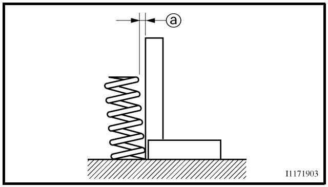
3. Measure:
- Spring tilt ⓐ
Out of specification → Replace.

Spring tilt limit:
Intake:
2.5°/1.7 mm (0.067 in)
Exhaust:
2.5°/1.6 mm (0.063 in)
natural_image
Simple line drawing of a cylinder (no text or symbols on the shape itself)
Valve lifter
1. Inspect:
- Valve lifter
Scratches/damage → Replace both lifters and cylinder head.
Ressort de soupape
- Mesurer:
ASSEMBLY AND INSTALLATION
1. Apply:
- Molybdenum disulfide oil
Onto the valve stem and valve stem seal.
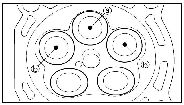
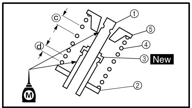
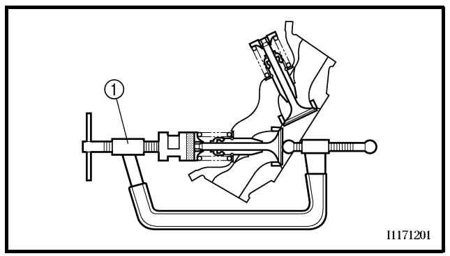
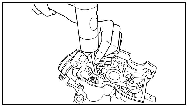
natural_image
Line drawing of a hand using a tool to adjust or install an engine component (no text or symbols present)
2. Install:
- Valves ①
- Valve spring seats ②
- Valve stem seals ③ New
- Valve springs ④
- Valve spring retainers ⑤
NOTE:
- Make sure that each valve is installed in its original place, also referring to the painted color as follows.
Intake (middle) ⓐ: blue
Intake (right/left) ⓑ: gray
Exhaust: not paint
- Install the valve springs with the larger pitch © facing upward.
(d) Smaller pitch
3. Install:
- Valve cotters
NOTE:
While compressing the valve spring with a valve spring compressor ① install the valve cotters.
Valve spring compressor: YM-4019/90890-04019
- To secure the valve cotters onto the valve stem, lightly tap the valve tip with a piece of wood.
CAUTION:
Hitting the valve tip with excessive force could damage the valve.
ASSEMBLAGE ET MONTAGE
1. Appliquer:
5. Install:
- Adjusting pad ①
- Valve lifter ②
NOTE:
- Apply the engine oil on the valve lifters.
- Apply the molybdenum disulfide oil on the valve stem end.
- Valve lifter must turn smoothly when rotated with a finger.
- Be careful to reinstall valve lifters and pads in their original place.
SOUPAPES ET RESSORTS DE SOUPAPES VENTILE UND VENTILFEDERN VÁLVULAS Y MUELLES DE VÁLVULAS
5. Monter:
Extent of removal:
① Cylinder removal
② Piston removal
| Extent of removal | Order | Part name | Q'ty | Remarks |
| Preparation for removal | | CYLINDER AND PISTON REMOVALCylinder head | | Refer to “CYLINDER HEAD” section. |
| 2 | 1 | Bolt (cylinder) | 1 | Use special tool.Refer to “REMOVAL POINTS”. |
| 2 | Cylinder | 1 |
| 3 | Gasket | 1 |
| 4 | Dowel pin | 2 |
| 5 | Piston pin clip | 2 |
| 6 | Piston pin | 1 |
| 7 | Piston | 1 |
| 8 | Piston ring set | 1 |
CYLINDRE ET PISTON
CYLINDRE ET PISTON
natural_image
Technical line drawing of a piston assembly with labeled component (no text or symbols beyond label)
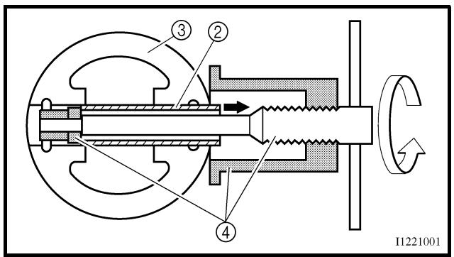
REMOVAL POINTS
Piston
-
Remove:
-
Piston pin clips ①
- Piston pin ②
- Piston ③
NOTE:
- Put identification marks on each piston head for reference during reinstallation.
- Before removing each piston pin, deburr the clip groove and pin hole area. If the piston pin groove is deburred and the piston pin is still difficult to remove, use the piston pin puller ④.
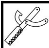
Piston pin puller:
YU-1304/90890-01304
CAUTION:
Do not use a hammer to drive the piston pin out.
Piston ring
- Remove:
- Piston rings
NOTE:
Spread the end gaps apart while at the same time lifting the piston ring over the top of the piston crown, as shown in the illustration.
INSPECTION
Cylinder and piston
- Inspect:
- Cylinder and piston walls
Vertical scratches → Replace cylinder and piston.
- Measure:
- Piston-to-cylinder clearance
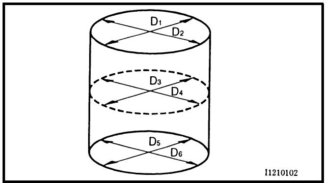
Measurement steps:
1st step:
- Measure the cylinder bore "C" with a cylinder bore gauge.
NOTE:
Measure the cylinder bore “C” in parallel to and at right angles to the crankshaft. Then, find the average of the measurements.
POINTS DE DEPOSE
Piston
| Cylinder bore “C” | 95.00 ~ 95.01 mm(3.7402 ~ 3.7406 in) |
| Taper limit “T” | 0.05 mm (0.002 in) |
| Out of round “R” | 0.05 mm (0.002 in) |
| “C” = Maximum D |
| “T” = (Maximum D1 or D2)– (Maximum D5 or D6) |
| “R” = (Maximum D1, D3 or D5)– (Minimum D2, D4 or D6) |
| • If out of specification, replace the cylinder,and replace the piston and piston rings as set.2nd step:• Measure the piston skirt diameter “P” witha micrometer.①8 mm (0.315 in) from the piston bottom edge |
| Piston size “P” |
| Standard | 94.945 ~ 94.960 mm(3.738 ~ 3.739 in) |
| • If out of specification, replace the pistonand piston rings as a set.3rd step:• Calculate the piston-to-cylinder clearancewith following formula: |
| Piston-to-cylinder clearance =Cylinder bore “C” –Piston skirt diameter “P” |
 | Piston-to-cylinder clearance:0.040 ~ 0.065 mm(0.0016 ~ 0.0026 in): 0.1 mm (0.004 in) |
| • If out of specification, replace the cylinder,and replace the piston and piston rings as set. |
natural_image
Line drawing of hands holding a circular object with a numbered label (1) on the top part, no text or symbols present.
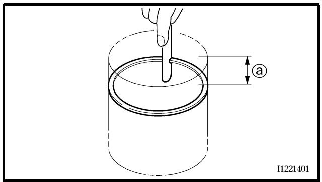
Piston ring
1. Measure:
- Ring side clearance
Use a feeler gauge ①.
Out of specification → Replace the piston and rings as a set.
NOTE:
Clean carbon from the piston ring grooves and rings before measuring the side clearance.
| Side clearance: |
| Standard | |
| Top ring | 0.030 ~ 0.065 mm(0.0012 ~ 0.0026 in) | 0.12 mm(0.005 in) |
| 2nd ring | 0.020 ~ 0.055 mm(0.0008 ~ 0.0022 in) | 0.12 mm(0.005 in) |
2. Position:
- Piston ring (in cylinder)
NOTE:
Insert a ring into the cylinder and push it approximately 10 mm (0.39 in) into the cylinder. Push the ring with the piston crown so that the ring will be at a right angle to the cylinder bore.
① 10 mm (0.39 in)
3. Measure:
- Ring end gap
Out of specification → Replace.
NOTE:
You cannot measure the end gap on the expander spacer of the oil control ring. If the oil control ring rails show excessive gap, replace all three rings.
 | End gap: |
| Standard | |
| Top ring | 0.20 ~ 0.30 mm(0.008 ~ 0.012 in) | 0.55 mm(0.022 in) |
| 2nd ring | 0.35 ~ 0.50 mm(0.014 ~ 0.020 in) | 0.85 mm(0.033 in) |
| Oil ring | 0.20 ~ 0.50 mm(0.01 ~ 0.02 in) | — |
Segment de piston
1. Mesurer:
natural_image
Illustration of a hand using a micrometer to measure a tool, showing measurement setup (no text or symbols)
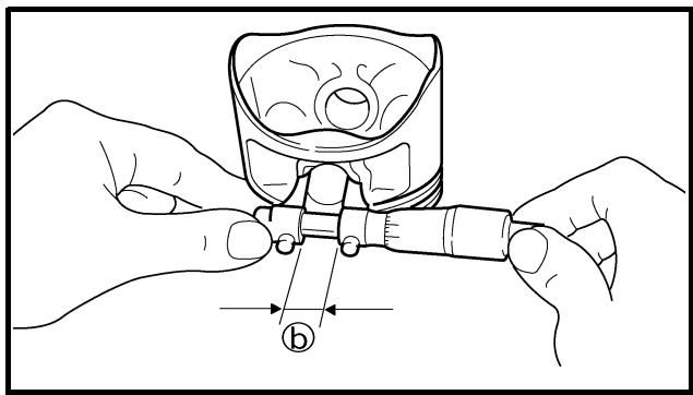
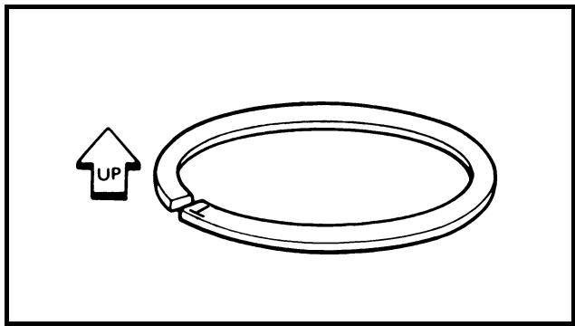
natural_image
Simple line drawing of a loop with an upward arrow labeled 'UP' (no text or symbols beyond the label)
Piston pin
1. Inspect:
- Piston pin
Blue discoloration/grooves → Replace, then inspect the lubrication system.
2. Measure:
- Piston pin-to-piston clearance
| Measurement steps:Measure the outside diameter (piston pin)a.If out of specification, replace the piston pin. |
 | Outside diameter (piston pin):17.991 ~ 18.000 mm(0.7083 ~ 0.7087 in) |
| Measure the inside diameter (piston) b. |
 | Inside diameter (piston):18.004 ~ 18.015 mm(0.7088 ~ 0.7093 in) |
| Calculate the piston pin-to-piston clearance with the following formula. |
 | pin-to-piston clearance =de diameter (piston) b -side diameter (piston pin) a |
| If out of specification, replace the piston. |
 | Piston pin-to-piston clearance:0.004 ~ 0.024 mm(0.00016 ~ 0.00094 in): 0.07 mm (0.003 in) |
ASSEMBLY AND INSTALLATION
Piston
1. Install:
- Piston rings
Onto the piston.
NOTE:
- Be sure to install the piston rings so that the manufacturer's marks or numbers are located on the upper side of the rings.
- Lubricate the piston and piston rings liberally with engine oil.
Axe de piston
- Contrôler:
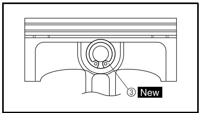
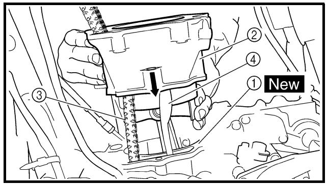
2. Position:
- Top ring
- 2nd ring
- Oil ring
Offset the piston ring end gaps as shown.
① Top ring end
⑥ 2nd ring end
© Oil ring end (upper)
d Oil ring
© Oil ring end (lower)
3. Install:
- Piston ①
- Piston pin ②
- Piston pin clips ③ New
NOTE:
- Apply engine oil onto the piston pin and piston.
- Be sure that the arrow mark ⓐ on the piston points to the exhaust side of the engine.
- Before installing the piston pin clip, cover the crankcase with a clean rag to prevent the piston pin clip from falling into the crankcase.
- Install the piston pin clips with their ends facing downward.
4. Lubricate:
- Piston
- Piston rings
- Cylinder
NOTE:
Apply a liberal coating of engine oil.
Cylinder
1. Install:
New
NOTE:
Install the cylinder with one hand while compressing the piston rings with the other hand.
CAUTION:
- Pass the timing chain ③ through the timing chain cavity.
- Be careful not to damage the timing chain guide ④ during installation.
2. Install:
- Bolt (cylinder)
10 Nm (1.0 m · kg, 7.2 ft · lb)
2. Position:
Extent of removal:
① Push rod and push lever removal
② Push rod 1 disassembly
③ Friction plate and clutch plate removal
④ Clutch housing removal
| Extent of removal | Order | Part name | Q'ty | Remarks |
| Preparation for removal | | CLUTCH REMOVALDrain the engine oil.Brake pedalClutch cable | | Refer to “ENGINE OIL REPLACEMENT” section in the CHAPTER 3.Refer to “ENGINE REMOVAL” section.Disconnect at engine side. |
| 1234↓1↓3↓4↓10↓11 | 1 | Clutch cover | 1 | |
| 2 | Gasket | 1 |
| 3 | Dowel pin | 2 |
| 4 | Clutch spring | 6 |
| 5 | Pressure plate | 1 |
| 6 | Push rod 1 | 1 |
| 7 | Circlip | 1 |
| 8 | Plain washer | 1 |
| 9 | Bearing | 1 |
| 10 | Ball | 1 |
| 11 | Push rod 2 | 1 |
EMBRAYAGE
EMBRAYAGE
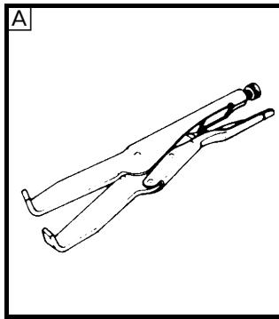
natural_image
Line drawing of a pair of scissors or clips in a diagonal arrangement (no text or symbols)
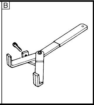
natural_image
Technical line drawing of a mechanical clamp or bracket (no text or symbols)
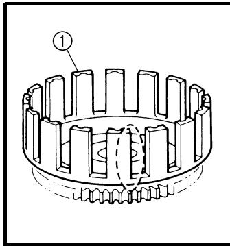
natural_image
Technical line drawing of a mechanical gear assembly with no visible text or symbols
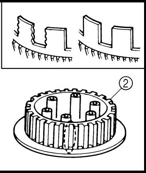
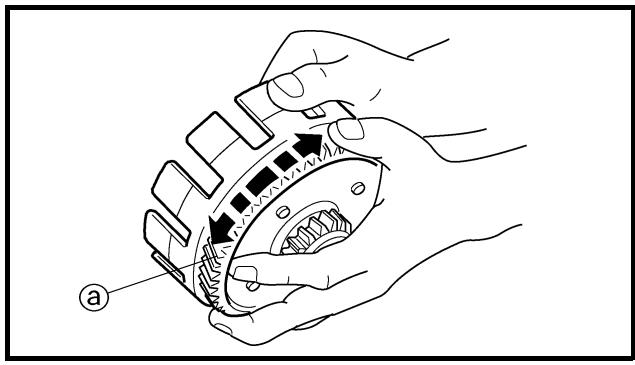
natural_image
Illustration of hands assembling a mechanical gear assembly (no text or symbols)
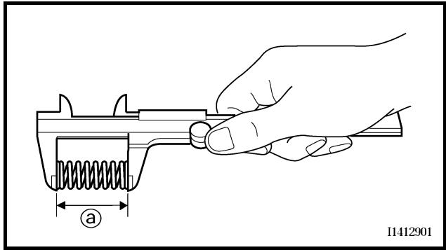
EC493000
REMOVAL POINTS
EC483211
Clutch boss
-
Remove:
-
Nut ①
- Lock washer ②
- Clutch boss ③
NOTE:
Straighten the lock washer tab and use the clutch holding tool ④ to hold the clutch boss.
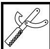
Clutch holding tool: YM-91042/90890-04086
A For USA and CDN
B Except for USA and CDN
EC494000
INSPECTION
EC484100
Clutch housing and boss
-
Inspect:
-
Clutch housing ①
Cracks/wear/damage → Replace.
- Clutch boss ②
Scoring/wear/damage → Replace.
EC484201
Primary driven gear
-
Check:
-
Circumferential play
Free play exists → Replace.
- Gear teeth ⓐ
Wear/damage → Replace.
EC484400
Clutch spring
-
Measure:
-
Clutch spring free length @
Out of specification → Replace springs as a set.

Clutch spring free length:
| Standard | |
| 50.0 mm (1.97 in) | 49.0 mm (1.93 in) |
POINTS DE DEPOSE
Noix d'embrayage
natural_image
Line drawing of hands using a tool to cut a gear (no text or symbols)
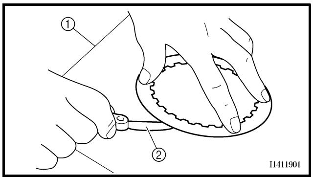
EC484500
Friction plate
1. Measure:
- Friction plate thickness
Out of specification → Replace friction plate as a set.
Measure at all four points.

Friction plate thickness:
2.92 \~ 3.08 mm
(0.115 \~ 0.121 in)
: 2.8 mm (0.110 in)
EC484600
Clutch plate
1. Measure:
- Clutch plate warpage
Out of specification → Replace clutch plate as a set.
Use a surface plate ① and thickness gauge ②.

Warp limit:
0.1 mm (0.004 in)
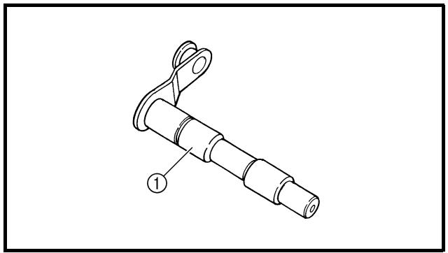
natural_image
Technical line drawing of a mechanical component with labeled part (1), no text or symbols present
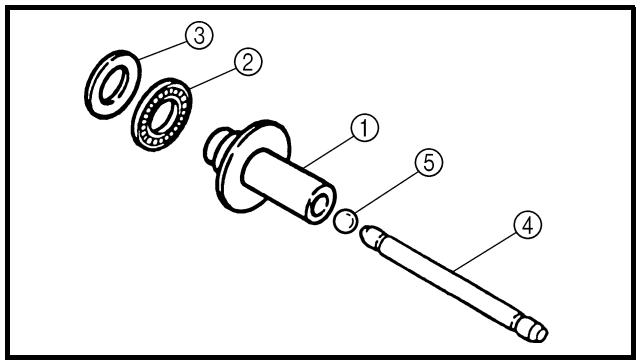
Push lever
1. Inspect:
- Push lever ①
Wear/damage → Replace.
EC484810
Push rod
1. Inspect:
- Push rod 1 ①
- Bearing ②
- Plain washer ③
- Push rod 2 ④
- Ball ⑤
Wear/damage/bend → Replace.
Disque garni
1. Mesurer:
EC4A5000
ASSEMBLY AND INSTALLATION
Push lever
- Install:
- Push lever ①
NOTE:
- Apply the lithium soap base grease on the oil seal lip.
- Apply the engine oil on the push lever.
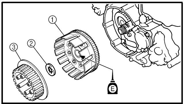
Clutch
- Install:
• Primary driven gear ①
- Thrust washer ②
- Clutch boss ③
NOTE:
Apply the engine oil on the primary driven gear inner circumference.
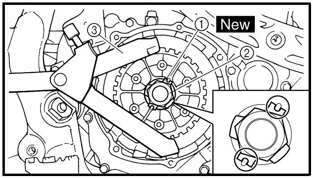
- Install:
- Lock washer ①
New
- Nut (clutch boss) ②
- Install the lock washer with its concaves fitted over the convexes of the clutch boss.
- Use the clutch holding tool ③ to hold the clutch boss.
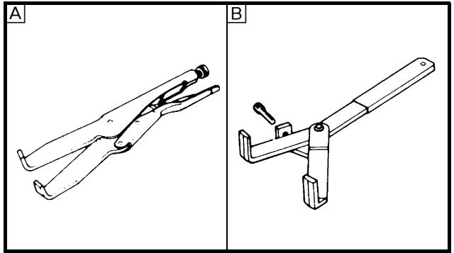
natural_image
Technical line drawings of two different clamp or tool holders (A and B) with no visible text or symbols
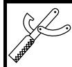
A For USA and CDN
B Except for USA and CDN
ASSEMBLAGE ET MONTAGE
Tige de poussée
- Monter:
- Tige de poussée ①
N.B.:
natural_image
Technical line drawing of a mechanical gear assembly (no text or symbols)
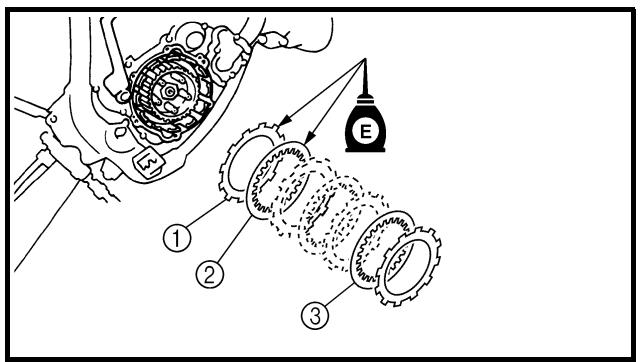
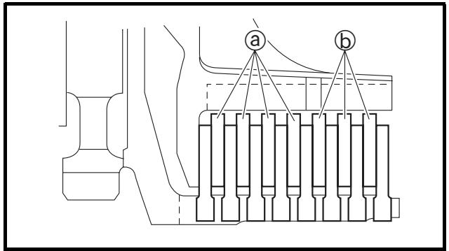
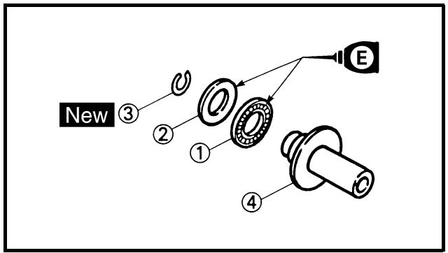
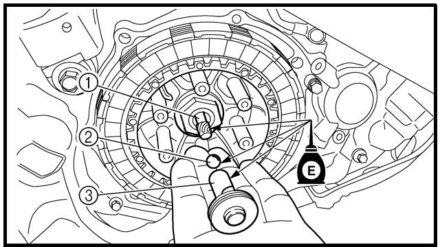
-
Bend the lock washer ① tab.
-
Install:
-
Friction plate ①
- Clutch plate 1
[t = 2.0 mm (0.079 in)] ②
- Clutch plate 2
[t = 1.6 mm (0.063 in)] ③
NOTE:
To push rod 1 ④.
NOTE:
Apply the engine oil on the bearing and plain washer.
-
Install:
-
Push rod 2 ①
- Ball ②
- Push rod 1 ③
NOTE:
Apply the engine oil on the push rod 1, 2 and ball.
-
Replier l'onglet de la rondelle-frein
①.
-
Die Lasche ① der Sicherungsscheibe umbiegen.
-
Doble la solapa de la arandela de seguridad ①.
-
Monter:
-
Disque garni ①
- Plateau de pression 1
[t = 2,0 mm (0,079 in)] ②
- Plateau de pression 2
[t = 1,6 mm (0,063 in)] ③
N.B.:
natural_image
Mechanical assembly diagram showing a clamping mechanism with no visible text or symbols
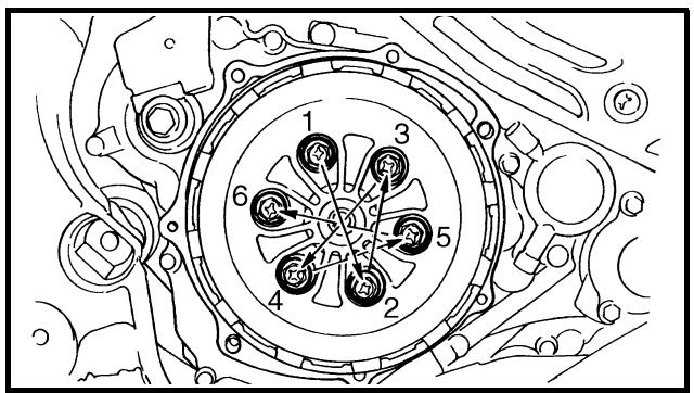
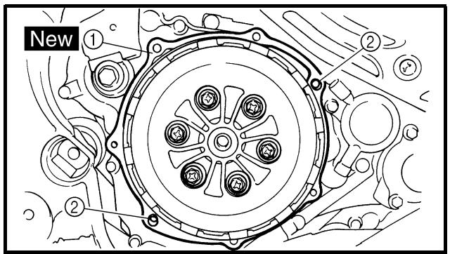
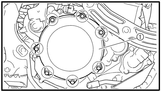
7. Install:
- Pressure plate ①
8. Install:
- Clutch spring
- Bolt (clutch spring)
10 Nm (1.0 m · kg, 7.2 ft · lb)
NOTE:
Tighten the bolts in stage, using a crisscross pattern.
9. Install:
- Gasket (clutch cover) ①
New
- Dowel pin ②
10. Install:
- Clutch cover ①
- Bolt (clutch cover)
10 Nm (1.0 m · kg, 7.2 ft · lb)
NOTE:
Tighten the bolts in stage, using a crisscross pattern.
7. Monter:
Extent of removal:
① Oil filter removal
③ Crankcase cover (right) removal
② Water pump removal
| Extent of removal | Order | Part name | Q'ty | Remarks |
| Preparation for removal | | OIL FILTER, WATER PUMP AND CRANKCASE COVER (RIGHT) REMOVALDrain the engine oil.Drain the coolant.Exhaust pipeBrake pedalClutch cover | | Refer to “ENGINE OIL REPLACEMENT” section in the CHAPTER 3.Refer to “COOLANT REPLACEMENT” section in the CHAPTER 3.Refer to “EXHAUST PIPE AND SILENCER” section.Refer to “ENGINE REMOVAL” section.Refer to “CLUTCH” section. |
| 1 | Oil filter cover | 1 | |
| 2 | Oil filter | 1 |
| 3 | Coolant pipe 2 | 1 |
| 4 | Water pump housing | 1 |
| 5 | Pin | 2 |
| 6 | Oil tank breather hose | 1 |
FILTRE A HUILE, POMPE A EAU ET COUVERCLE DE CARTER MOTEUR (DROIT)
FILTRE A HUILE, POMPE A EAU ET COUVERCLE DE CARTER MOTEUR (DROIT)
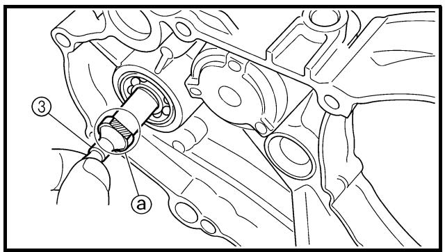
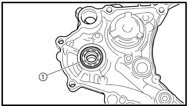
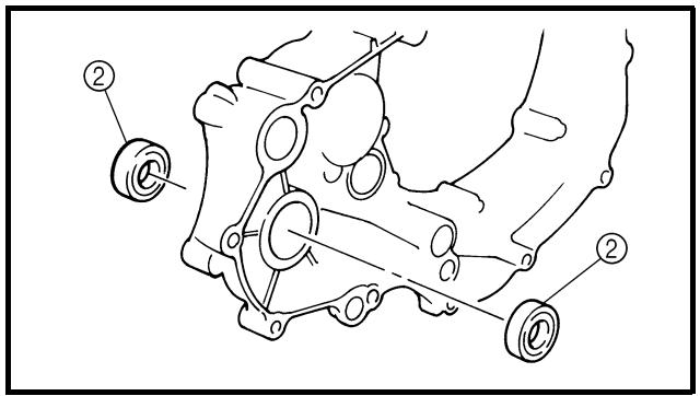
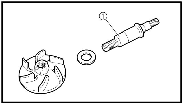
natural_image
Technical illustration of a mechanical component with a gear and threaded shaft (no text or symbols)
REMOVAL POINTS
EC4G3110
Impeller shaft
-
Remove:
-
Impeller ①
- Plain washer ②
- Impeller shaft ③
NOTE:
Hold the impeller shaft on its width across the flats ⓐ with spanners, etc. and remove the impeller.
EC4G3210
Oil seal
NOTE:
It is not necessary to disassemble the water pump, unless there is an abnormality such as excessive change in coolant level, discoloration of coolant, or milky transmission oil.
-
Remove:
-
Bearing ①
- Oil seal ②
INSPECTION
EC444200
Impeller shaft
- Inspect:
- Impeller shaft ①
Bend/wear/damage → Replace.
Fur deposits → Clean.
POINTS DE DEPOSE
Axe de pompe
- Bearing
Rotate inner race with a finger.
Rough spot/seizure → Replace.
EC444400
Oil seal
1. Inspect:
- Oil seal
Wear/damage → Replace.
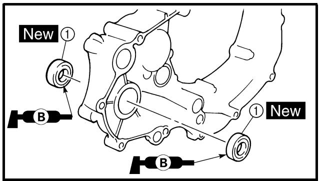
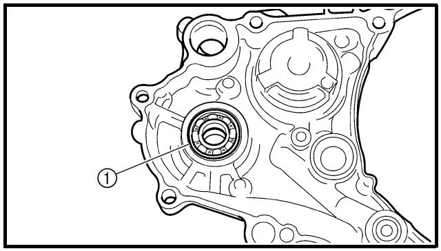
ASSEMBLY AND INSTALLATION
EC4G5110
Oil seal
1. Install:
- Oil seal ① New
NOTE:
- Apply the lithium soap base grease on the oil seal lip.
- Install the oil seal with its manufacture's marks or numbers facing inward.
Bearing
1. Install:
- Bearing ①
NOTE:
Install the bearing by pressing its outer race parallel.
Roulement
- Contrôler:
- Roulement
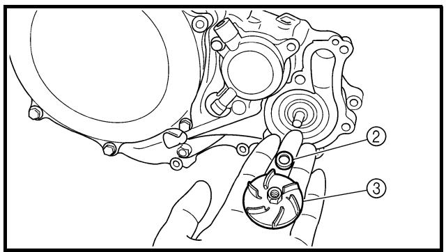
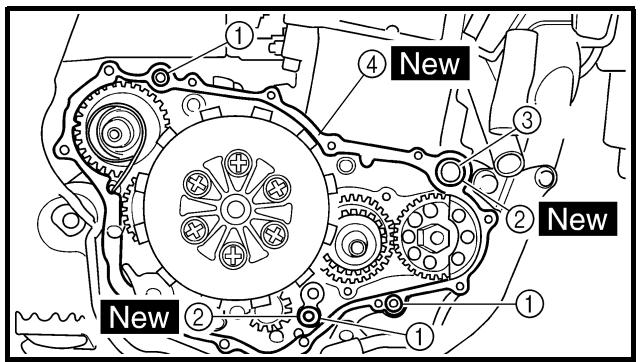
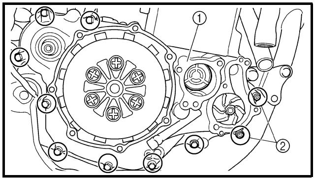
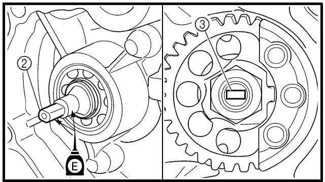
EC4G5220
Impeller shaft
1. Install:
- Impeller shaft ①
- Plain washer ②
- Impeller ③
14 Nm (1.4 m · kg, 10 ft · lb)
NOTE:
- Take care so that the oil seal lip is not damaged or the spring does not slip off its position.
- When installing the impeller shaft, apply the engine oil on the oil seal lip, bearing and impeller shaft. And install the shaft while turning it.
- Hold the impeller shaft on its width across the flats ⓐ with spanners, etc. and install the impeller.
Crankcase cover (right)
1. Install:
- Dowel pin ①
- O-ring ② New
- Collar ③
- Gasket ④
New
2. Install:
- Crankcase cover (right) ①
- Bolt ②
- Bolt
12 Nm (1.2 m · kg, 8.7 ft · lb)
10 Nm (1.0 m · kg, 7.2 ft · lb)
NOTE:
- Apply the engine oil on the impeller shaft end.
- When installing the crankcase cover onto the crankcase, be sure that the impeller shaft end ② aligns with the balancer end slot ③.
- Tighten the bolts in stage, using a crisscross pattern.
Axe de pompe
-
Monter:
-
Axe de pompe ①
- Rondelle pleine ②
- Rotor ③
14 Nm (1,4 m · kg, 10 ft · lb)
N.B.:
Kick crank
1. Install:
- Kickstarter ①
- Plain washer
- Bolt (kickstarter)

Install so that there is a clearance ⓐ of 8 mm (0.31 in) or more between the kickstarter and frame and that the kickstarter does not contact the crankcase cover when it is pulled.
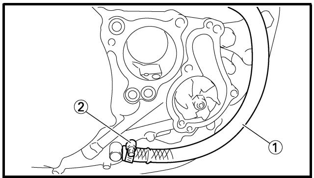
2. Install:
- Oil tank breather hose ①
- Clamp ②
2 Nm (0.2 m · kg, 1.4 ft · lb)
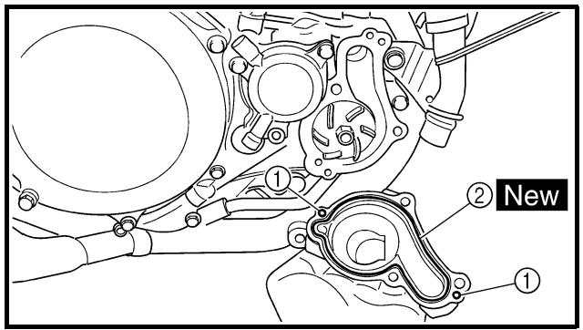
Water pump housing
1. Install:
2. Install:
• Water pump housing ①
- Bolt (water pump housing) ②
10 Nm (1.0 m · kg, 7.2 ft · lb)
- Plain washer ③ New
- Coolant drain bolt ④
10 Nm (1.0 m · kg, 7.2 ft · lb)
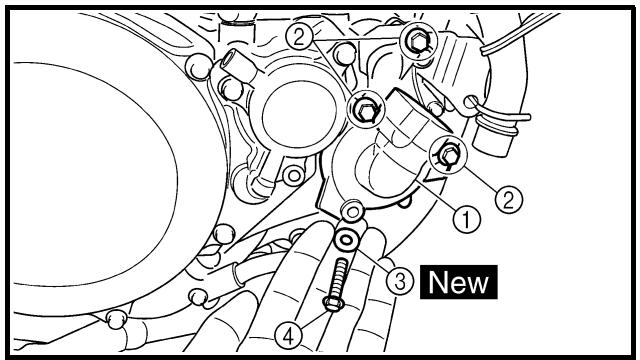
Lanceur au pied
-
Monter:
-
Kick ①
- Rondelle pleine
- Boulon (kick)

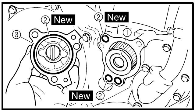
3. Install:
- O-ring
- Coolant pipe ①
- Bolt (coolant pipe) ②
10 Nm (1.0 m · kg, 7.2 ft · lb)
Oil filter
1. Install:
- Oil filter ①
- O-ring ② New
- Oil filter cover ③
- Bolt (oil filter cover)
10 Nm (1.0 m · kg, 7.2 ft · lb)
3. Monter:
Extent of removal:
① Balancer drive gear
② Balancer
| Extent of removal | Order | Part name | Q'ty | Remarks |
| Preparation for removal | | BALANCER REMOVALClutch housingCrankcase cover (right)Stator | | Refer to “CLUTCH” section.Refer to “OIL FILTER, WATER PUMP AND CRANKCASE COVER (RIGHT)” section.Refer to “AC MAGNETO AND STARTER CLUTCH” section. |
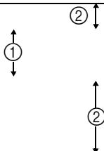 | 1 | Nut (balancer) | 1 | Refer to “REMOVAL POINTS”. |
| 2 | Nut (primary drive gear) | 1 |
| 3 | Nut (balancer driven gear) | 1 |
| 4 | Lock washer | 1 |
| 5 | Balancer | 1 |
| 6 | Straight key | 1 |
BALANCIER
BALANCIER
Extent of removal:
① Balancer drive gear
② Balancer
| Extent of removal | Order | Part name | Q'ty | Remarks |
| 1 | 7 | Conical washer | 1 | |
| 8 | Primary drive gear | 1 | |
| 9 | Balancer drive gear | 1 | |
| 10 | Lock washer | 1 | |
| 11 | Balancer driven gear | 1 | |
| Organisation de la dépose | Ordre | Nom de la pièce | Qté | Remarques |
| ### | 7 | Rondelle conique | 1 | |
| 8 | Pignon menant de transmission primaire | 1 | |
| 9 | Pignon menant du balancier | 1 | |
| 10 | Rondelle-frein | 1 | |
| 11 | Pignon mené du balancier | 1 | |
natural_image
Technical line drawing of a mechanical assembly with gears and springs (no text or symbols)
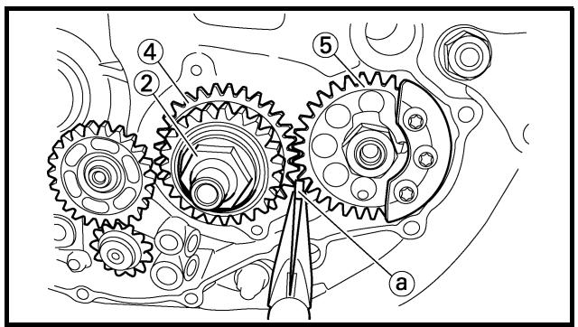
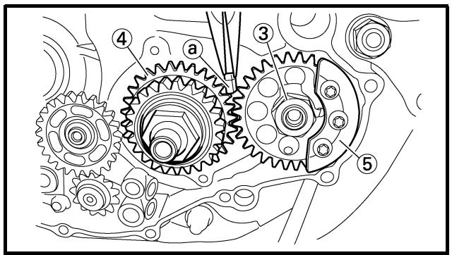
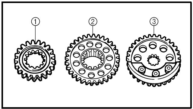

natural_image
Technical line drawing of a mechanical component with a flanged circular base and central bore (no text or symbols)
REMOVAL POINTS
Balancer, balancer drive gear and balancer driven gear
- Straighten the lock washer tab.
-
Loosen:
-
Nut (balancer) ①
- Nut (primary drive gear) ②
- Nut (balancer driven gear) ③
NOTE:
Place an aluminum plate ④ between the teeth of the balancer drive gear ④ and balancer driven gear ⑤.
INSPECTION
Primary drive gear, balancer drive gear and balancer driven gear
-
Inspect:
-
Primary drive gear ①
- Balancer drive gear ②
- Balancer driven gear ③
Wear/damage → Replace.
Balancer
- Inspect:
- Balancer
Cracks/damage → Replace.
POINTS DE DEPOSE
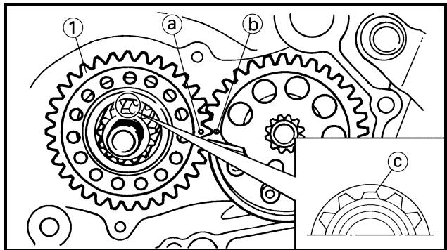
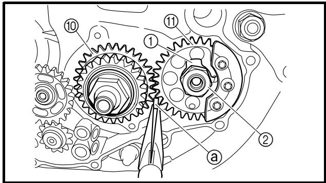
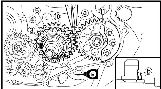
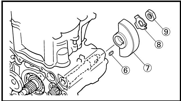
ASSEMBLY AND INSTALLATION
Balancer, balancer drive gear and balancer driven gear
1. Install:
- Balancer driven gear ①
NOTE:
Install the balancer driven gear and balancer shaft with their lower splines @ aligning with each other.
2. Install:
- Balancer drive gear ①
NOTE:
- Align the punched mark ⓐ on the balancer drive gear with the punched mark ⓑ on the balancer driven gear.
- Install the balancer driven gear and crankshaft with the lower splines © aligning with each other.
3. Install:
- Lock washer ①
- Nut (balancer driven gear) ②

- Primary drive gear ③
- Conical washer ④
- Nut (primary drive gear) ⑤

- Straight key ⑥
- Balancer ⑦
- Lock washer ⑧
- Nut (balancer) ⑨

NOTE:
Extent of removal:
① Oil pump removal
② Oil pump disassembly
| Extent of removal | Order | Part name | Q'ty | Remarks |
| Preparation for removal | | OIL PUMP REMOVAL AND DISASSEMBLYClutch housingCrankcase cover (right) | | Refer to “CLUTCH” section.Refer to “OIL FILTER, WATER PUMP AND CRANKCASE COVER (RIGHT)” section. |
| 12 | 1 | Circlip | 1 | |
| 2 | Plain washer | 1 |
| 3 | Oil pump drive gear | 1 |
| 4 | Oil pump assembly | 1 |
| 5 | Dowel pin | 2 |
| 6 | Outer rotor 2 | 1 |
| 7 | Circlip | 1 |
| 8 | Inner rotor 2 | 1 |
| 9 | Pin | 1 |
| 10 | Oil pump cover | 1 |
| 11 | Outer rotor 1 | 1 |
| 12 | Inner rotor 1 | 1 |
POMPE A HUILE
POMPE A HUILE
- Oil pump drive gear
- Oil pump driven gear
- Rotor housing
- Oil pump cover
Cracks/wear/damage → Replace.
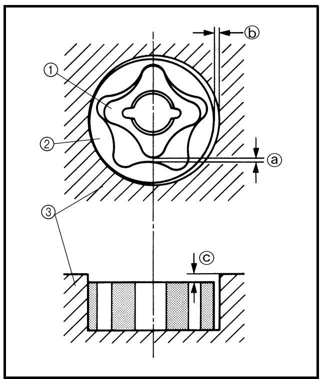
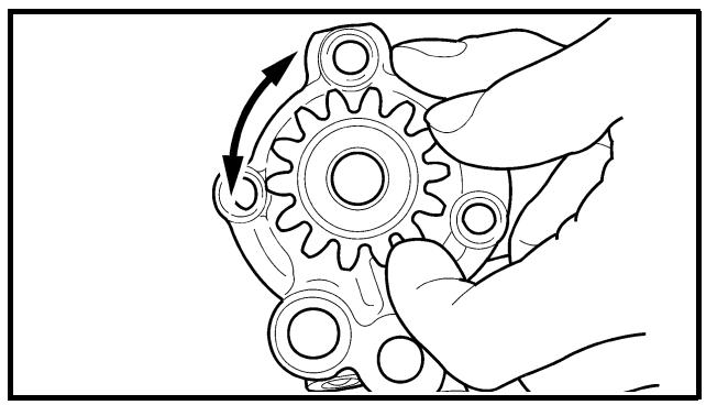
natural_image
Line drawing of a hand turning a gear with an arrow indicating rotational motion (no text or symbols)
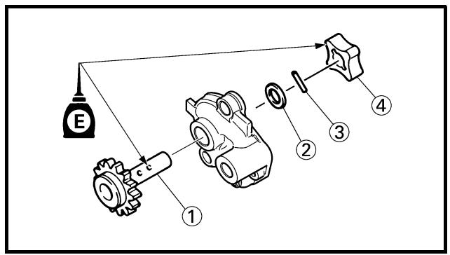
2. Measure:
- Tip clearance ⓐ
Between the inner rotor ① and the outer rotor ②.
- Tip clearance ⓑ
Between the outer rotor ② and the rotor housing ③.
Out of specification → Replace the oil pump.

Tip clearance ⓐ:
0.12 mm or less
(0.0047 in or less)
: 0.20 mm (0.008 in)
Tip clearance ⓑ:
0.09 \~ 0.17 mm
(0.0035 \~ 0.0067 in)
: 0.24 mm (0.009 in)
Side clearance ©:
0.03 \~ 0.10 mm
(0.0012 \~ 0.0039 in)
: 0.17 mm (0.007 in)
3. Check:
- Unsmooth → Repeat steps #1 and #2 or replace the defective parts.
ASSEMBLY AND INSTALLATION
Oil pump
1. Install:
- Oil pump drive shaft ①
- Washer ②
- Pin ③
- Inner rotor 1 ④
NOTE:
- Apply the engine oil on the oil pump drive shaft and inner rotor 1.
- Fit the pin into the groove in the inner rotor 1.
CONTROLE
Pompe à huile
1. Contrôler:
2. Install:
- Outer rotor 1 ①
NOTE:
Apply the engine oil on the outer rotor 1.
3. Install:
- Oil pump cover ①
- Screw (oil pump cover) ②
2 Nm (0.2 m · kg, 1.4 ft · lb)
- Pin ③
- Inner rotor 2 ④
- Circlip ⑤ New
NOTE:
- Apply the engine oil on the oil pump drive shaft end and inner rotor 2.
- Fit the pin into the groove in the inner rotor 2.
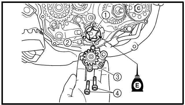
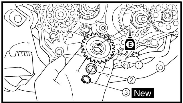
4. Install:
- Outer rotor 2 ①
- Dowel pin ②
- Oil pump assembly ③
- Bolt (oil pump assembly) ④
10 Nm (1.0 m · kg, 7.2 ft · lb)
NOTE:
Apply the engine oil on the outer rotor 2.
5. Install:
- Oil pump drive gear ①
- Plain washer ②
- Circlip ③ New
NOTE:
Apply the engine oil on the oil pump drive gear inner circumference.
2. Monter:
- Rotor externe 1 ①
N.B.:
KICK AXLE AND SHIFT SHAFT
KICK AXLE AND SHIFT SHAFT

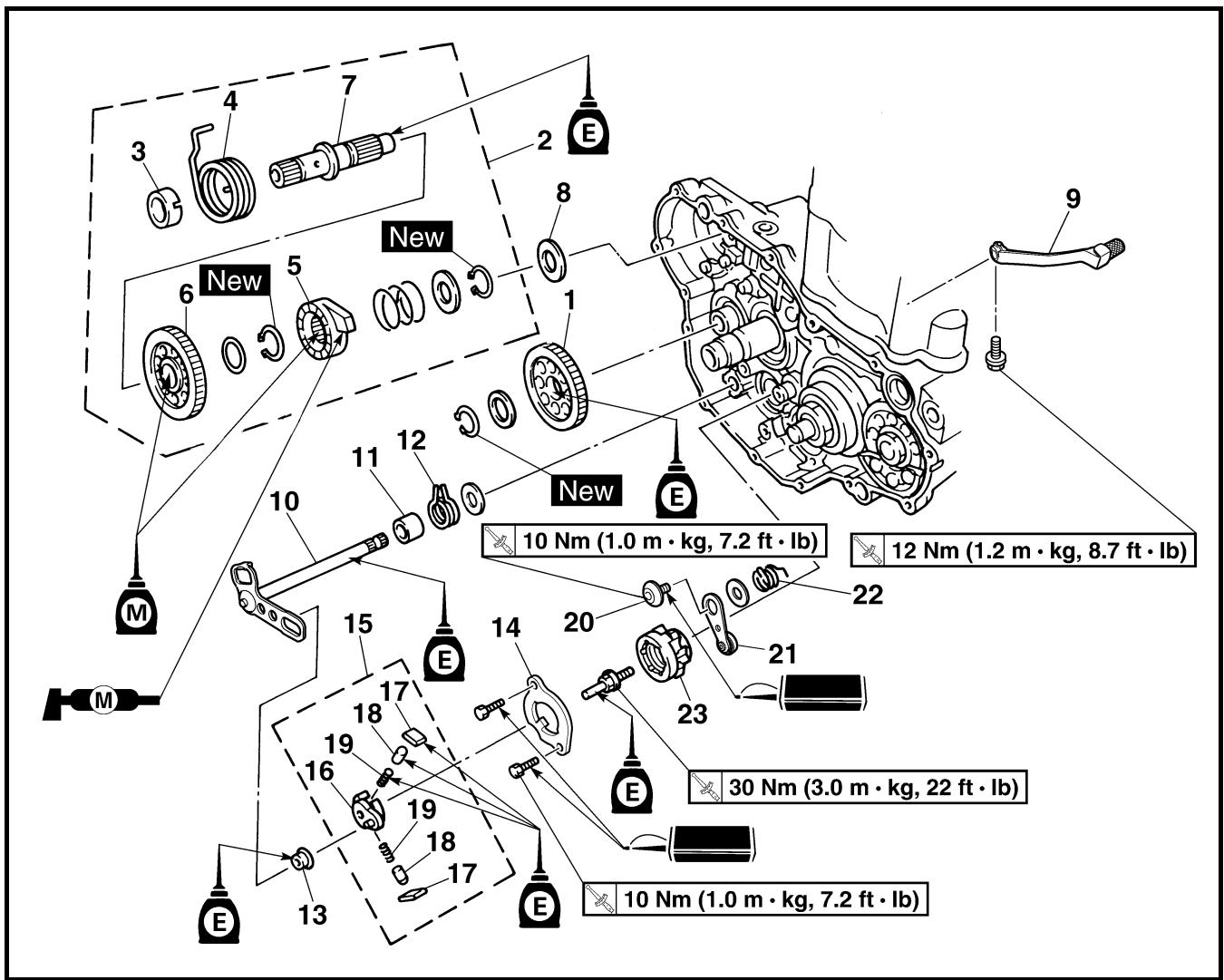
Extent of removal:
① Kick axle removal
③ Shift shaft removal
② Kick axle disassembly
④ Segment removal
| Extent of removal | Order | Part name | Q'ty | Remarks |
| Preparation for removal | | KICK AXLE AND SHIFT SHAFT REMOVALOil pump | | Refer to “OIL PUMP” section. |
| 1↓2↓1↓3↓4↓ | 1 | Kick idle gear | 1 | Refer to “REMOVAL POINTS”. |
| 2 | Kick axle assembly | 1 |
| 3 | Spring guide | 1 |
| 4 | Torsion spring | 1 |
| 5 | Ratchet wheel | 1 |
| 6 | Kick gear | 1 |
| 7 | Kick axle | 1 |
| 8 | Plain washer | 1 |
| 9 | Shift pedal | 1 |
| 10 | Shift shaft | 1 |
| 11 | Collar | 1 |
| 12 | Torsion spring | 1 |
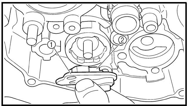
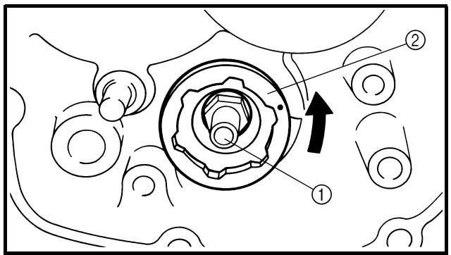
REMOVAL POINTS
EC4B3101
Kick axle assembly
- Remove:
- Kick axle assembly ①
NOTE:
Unhook the torsion spring ② from the hole ④ in the crankcase.
EC4C3101
Shift guide and shift lever assembly
-
Remove:
-
Bolt (shift guide)
- Shift guide ①
- Shift lever assembly ②
NOTE:
The shift lever assembly is disassembled at the same time as the shift guide.
EC4N3100
Segment
-
Remove:
-
Bolt (segment) ①
- Segment ②
NOTE:
Turn the segment counterclockwise until it stops and loosen the bolt.
CAUTION:
If the segment gets an impact, it may be damaged. Take care not to give an impact to the segment when removing the bolt.
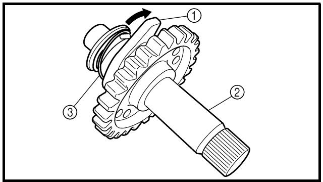
INSPECTION
EC4C4200
Kick axle and ratchet wheel
-
Check:
-
Ratchet wheel ① smooth movement Unsmooth movement → Replace.
- Kick axle ②
Wear/damage → Replace.
- Spring ③
Broken → Replace.
POINTS DE DEPOSE
Arbre de kick complet
- Déposer:
-
Déposer:
-
Boulon (segment) ①
- Segment ②
N.B.:
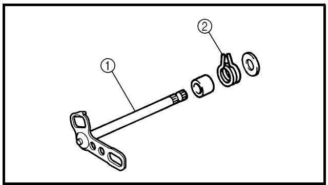
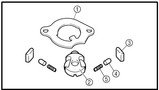
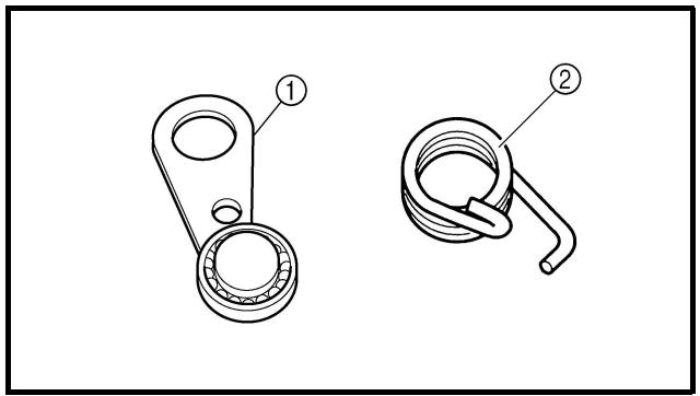
EC4C4300
Kick gear, kick idle gear and ratchet wheel
1. Inspect:
- Kick gear ①
- Kick idle gear ②
- Ratchet wheel ③
- Gear teeth ⓐ
- Ratchet teeth ⓑ
Wear/damage → Replace.
EC4B4400
Shift shaft
1. Inspect:
- Shift shaft ①
Bend/damage → Replace.
- Spring ②
Broken → Replace.
EC4C4100
Shift guide and shift lever assembly
1. Inspect:
- Shift guide ①
- Shift lever ②
- Pawl ③
- Pawl pin ④
- Spring ⑤
Wear/damage → Replace.
EC4B4500
Stopper lever
1. Inspect:
- Stopper lever ①
Wear/damage → Replace.
- Torsion spring ②
Broken → Replace.
EC4C5000
ASSEMBLY AND INSTALLATION
Segment
-
Install:
-
Segment ①
- Bolt (segment)
30 Nm (3.0 m · kg, 22 ft · lb)
NOTE:
Align the notch ⓐ on the segment with the pin ⓑ on the shift cam.
CAUTION:
If the segment gets an impact, it may be damaged. Take care not to give an impact to the segment when tightening the bolt.
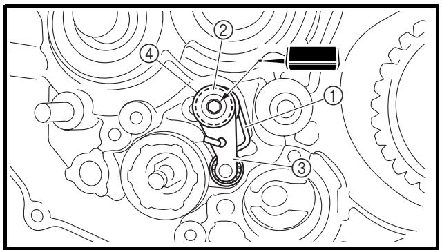
EC4B5111
Stopper lever
-
Install:
-
Torsion spring ①
- Plain washer ②
- Stopper lever ③
- Bolt (stopper lever) ④

10 Nm (1.0 m · kg, 7.2 ft · lb)
NOTE:
Align the stopper lever roller with the slot on segment.
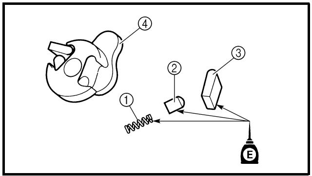
Shift guide and shift lever assembly
-
Install:
-
Spring ①
- Pawl pin ②
- Pawl ③
To shift lever ④.
NOTE:
Apply the engine oil on the springs, pawl pins and pawls.
- Install:
- Shift lever assembly ①
To shift guide ②.
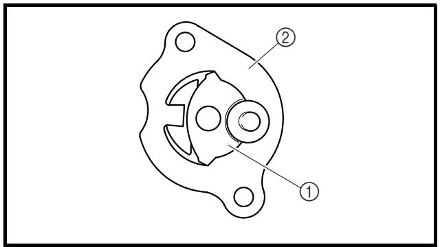
ASSEMBLAGE ET MONTAGE
Segment
-
Monter:
-
Segment ①
- Boulon (segment)
30 Nm (3,0 m · kg, 22 ft · lb)
N.B.:
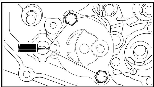
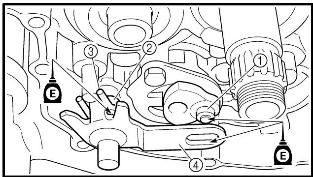
3. Install:
- Shift lever assembly ①
- Shift guide ②
NOTE:
- The shift lever assembly is installed at the same time as the shift guide.
- Apply the engine oil on the bolt (segment) shaft.
4. Install:
- Bolt (shift guide) ①

10 Nm (1.0 m · kg, 7.2 ft · lb)
EC4C5301
Shift shaft
1. Install:
- Roller ①
- Collar ②
- Torsion spring ③
- Plain washer ④
- Shift shaft ⑤
NOTE:
Apply the engine oil on the roller and shift shaft.
2. Install:
- Shift pedal
Refer to "AC MAGNETO AND STARTER CLUTCH" section.
3. Monter:
Kick axle assembly
1. Install:
- Kick gear ①
- Plain washer ②
- Circlip ③ New
- Ratchet wheel ④
- Spring ⑤
- Plain washer ⑥
- Circlip ⑦ New
To kick axle ⑧.
NOTE:
- Apply the molybdenum disulfide oil on the inner circumferences of the kick gear and ratchet wheel.
- Align the punch mark ⓐ on the ratchet wheel with the punch mark ⓑ on the kick axle.
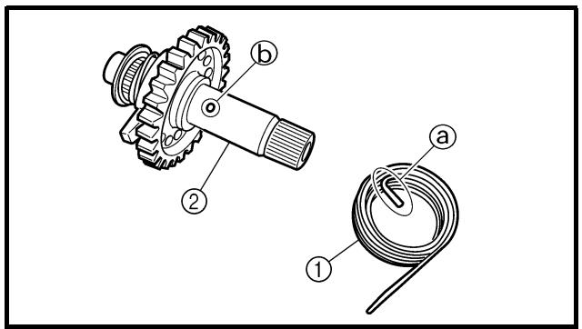
2. Install:
- Torsion spring ①
To kick axle ②.
NOTE:
Make sure the stopper Ⓐ of the torsion spring fits into the hole ⓑ on the kick axle.
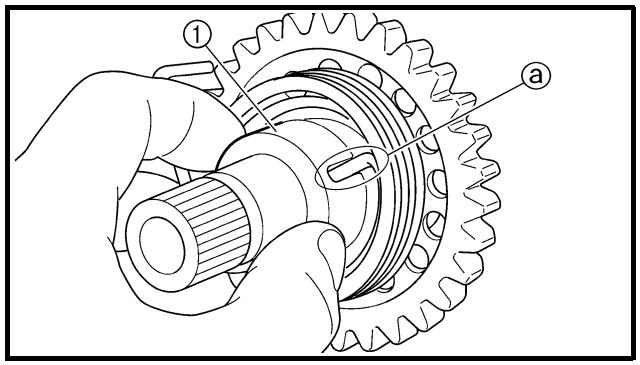
3. Install:
- Spring guide ①
NOTE:
Slide the spring guide into the kick axle, make sure the groove ⓐ in the spring guide fits on the stopper of the torsion spring.
Arbre de kick complet
- Monter:
- Pignon de kick ①
- Rondelle pleine ②
- Circlip ③ New
- Roue à rochet ④
- Ressort ⑤
- Rondelle pleine ⑥
- Circlip ⑦ New
4. Install:
- Kick axle assembly ①
- Plain washer ②
NOTE:
- Apply the molybdenum disulfide grease on the contacting surfaces of the kick axle stopper ⑨ and ratchet wheel guide ③.
- Apply the engine oil on the kick axle.
- Slide the kick axle assembly into the crank-case and make sure the kick axle stopper fits into the ratchet wheel guide.
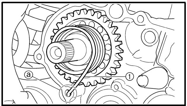
natural_image
Technical line drawing of a mechanical gear assembly with labeled components (a, 1, 2), no readable text or symbols beyond labels
5. Hook:
- Torsion spring ①
NOTE:
Turn the torsion spring clockwise and hook into the proper hole ⓐ in the crankcase.
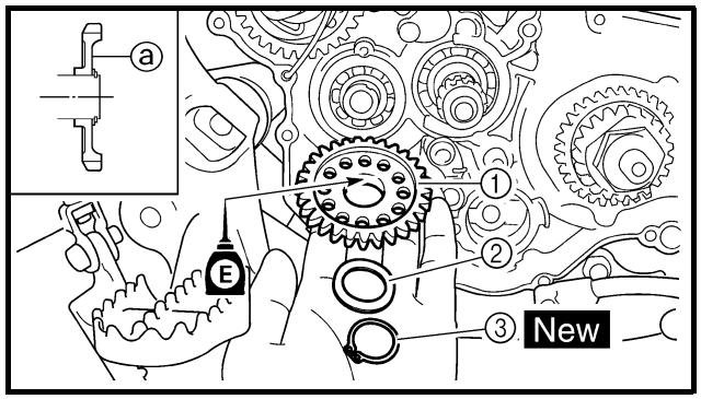
Kick idle gear
1. Install:
- Kick idle gear ①
- Plain washer ②
- Circlip ③ New
NOTE:
- Install the kick idle gear with its depressed side @ toward you.
- Apply the engine oil on the kick idle gear inner circumference.
4. Monter:
Extent of removal:
① Starter clutch/wheel gear removal
② Rotor removal
③ Pickup coil/stator removal
| Extent of removal | Order | Part name | Q'ty | Remarks |
| Preparation for removal | | AC MAGNETO AND STATOR REMOVALDrain the engine oil.Seat and fuel tankDisconnect the AC magneto lead. | | Refer to “ENGINE OIL REPLACEMENT” section in the CHAPTER 3.Refer to “SEAT, FUEL TANK AND SIDE COVERS” section. |
| 13 | 1 | Shift pedal | 1 | Do not disassemble. |
| 2 | Cover (torque limiter) | 1 |
| 3 | Torque limiter | 1 |
| 4 | Crankcase cover (left) | 1 |
| 5 | Gasket | 1 |
| 6 | Dowel pin | 2 |
ALTERNATEUR AVEC ROTOR A ALIMENTATION PERMANENTE ET EMBRAYAGE DU DEMARREUR
| Extent of removal | Order | Part name | Q'ty | Remarks |
 | 7 | Idle gear | 1 | |
| 8 | Bearing | 1 | |
| 9 | Shaft | 1 | |
| 10* | Nut (rotor) | 1 | Refer to NOTE. |
| 11 | Rotor | 1 | Use special tool. |
| | | Refer to “REMOVAL POINTS”. |
| 12 | Woodruff key | 1 | |
| 13 | Starter clutch assembly cover | 1 | Refer to “REMOVAL POINTS”. |
| 14 | Starter clutch | 1 |
| 15 | Starter clutch drive gear | 1 |
| 16 | Holder | 1 |
| 17 | Pick-up coil | 1 |
| 18 | Stator | 1 |
NOTE:
Tighten the rotor nut to 65 Nm (6.5 m • kg, 47 ft • lb), loosen and retighten the rotor nut to 65 Nm (6.5 m • kg, 47 ft • lb).
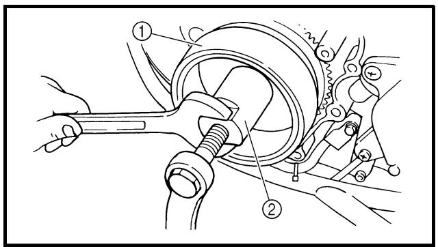
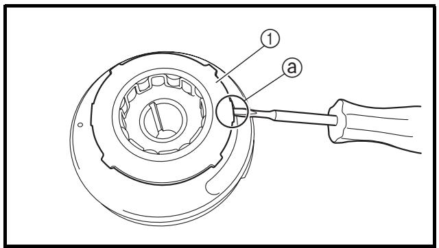
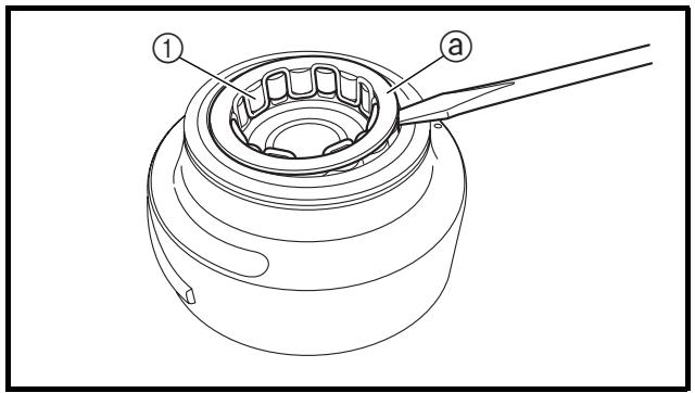
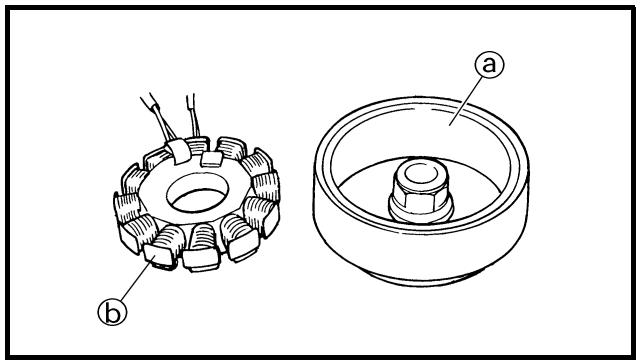
natural_image
Technical line drawing of a mechanical component with two views: top shows gear-like structure, bottom shows cylindrical housing (no text or symbols)
EC4L3000
REMOVAL POINTS
Rotor
-
Remove:
-
Nut (rotor) ①
- Plain washer
Use the sheave holder ②.
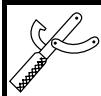
Sheave holder:
YS-1880-A/90890-01701
- Remove:
- Rotor ①
Use the rotor puller ②.
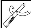
Rotor puller:
YM-04142/90890-04142
Starter clutch
- Remove:
- Starter clutch assembly cover ①
NOTE:
Insert a thin screwdriver or the like under the convexity ⓐ and remove the starter clutch assembly cover by prying it gently to void damage to the cover.
- Remove:
- Starter clutch ①
NOTE:
Using a thin screwdriver or the like, remove the plate @ while prying it upward little by little.
EC4L4000
INSPECTION
AC magneto
-
Inspect:
-
Rotor inner surface ⓐ
- Stator outer surface ⑥
Damage → Inspect the crankshaft runout and crankshaft bearing.
If necessary, replace AC magneto and/or stator.
POINTS DE DEPOSE
Rotor
natural_image
Technical line drawing of a mechanical assembly with no visible text or symbols
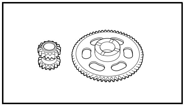
natural_image
Technical line drawing of two gear components (no text or symbols)
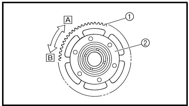
EC4L4200
Woodruff key
1. Inspect:
- Woodruff key ①
Damage → Replace.
Starter clutch
1. Check:
- Starter clutch
Damage/wear → Replace.
2. Check:
- Idle gear
- Idle gear shaft
- Starter clutch gear
Pitting/burrs/chips/roughness/wear → Replace the defective parts.
3. Check:
- Starter clutch operation
- Install the starter clutch drive gear ① onto the starter clutch ② and hold the starter clutch.
- When turning the starter clutch drive gear counterclockwise B, the starter clutch and the starter clutch drive gear should engage. If the starter clutch drive gear and starter clutch do not engage, the starter clutch is faulty and must be replaced.
- When turning the starter clutch drive gear clockwise A, it should turn freely.
If the starter clutch drive gear does not turn freely, the starter clutch is faulty and must be replaced.
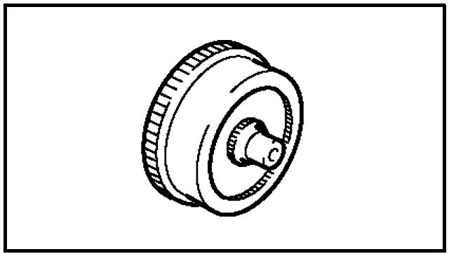
natural_image
Technical line drawing of a mechanical component with concentric rings and a central hub (no text or symbols)
Torque limiter
1. Check:
- Torque limiter
Damage/wear → Replace.
Clavette demi-lune
- Contrôler:
- Clavette demi-lune ①
Endommagement → Remplacer.
Scheibenfeder
- Kontrollieren:
EC4L5000
ASSEMBLY AND INSTALLATION
AC magneto and starter clutch
-
Install:
-
Stator ①
- Bolt (stator) ②
7 Nm (0.7 m · kg, 5.1 ft · lb)
- Pick-up coil ③
- Holder ④
- Bolt ⑤
10 Nm (1.0 m · kg, 7.2 ft · lb)
NOTE:
- Pass the AC magneto lead ⑤ under the pick-up coil.
- Pass the AC magneto lead ④ under the holder as shown.
- Take care not to catch the AC magneto lead between crankcase cover ribs.
- Tighten the bolt (stator) using the T25 bit.
- Apply the sealant to the grommet of the AC magneto lead.
YAMAHA Bond No. 1215
(ThreeBond ^® No. 1215):
90890-85505
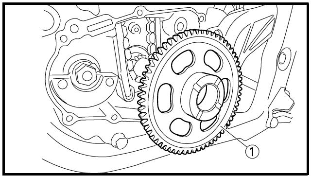
natural_image
Technical line drawing of a mechanical gear assembly with no visible text or symbols
- Install:
- Starter clutch drive gear ①
NOTE:
Apply the engine oil on the starter clutch drive gear inner circumference.
-
Monter:
-
Stator ①
- Boulon (stator) ②
7 Nm (0,7 m · kg, 5,1 ft · lb)
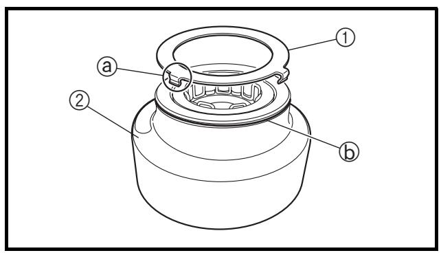
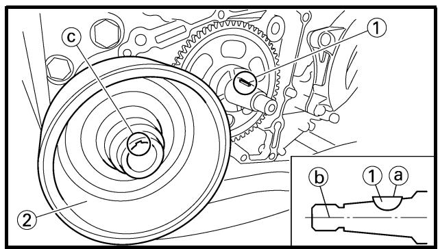
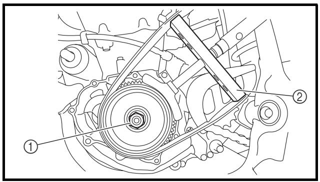
3. Install:
- Starter clutch ①
To rotor ②.
NOTE:
- Install the starter clutch with its plate side upward.
- While installing the starter clutch, push in the projections @ one by one on the clutch circumference.
- Push in the starter clutch until it hits the rotor.
4. Install:
- Starter clutch assembly cover ①
To rotor ②.
NOTE:
Install the starter clutch assembly cover by fitting its pawls ⓐ into the groove ⓑ in the rotor.
5. Install:
NOTE:
- Degrease the contact surfaces of the tapered portions of the crankshaft and rotor.
- When installing the woodruff key, make sure that its flat surface ⓐ is in parallel with the crankshaft center line ⓑ.
- When installing the rotor, align the keyway © of the rotor with the woodruff key.
6. Install:
- Plain washer (rotor)
- Nut (rotor) ①
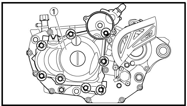
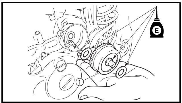
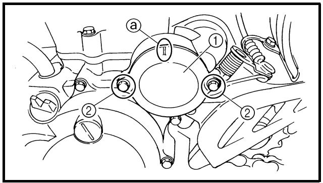
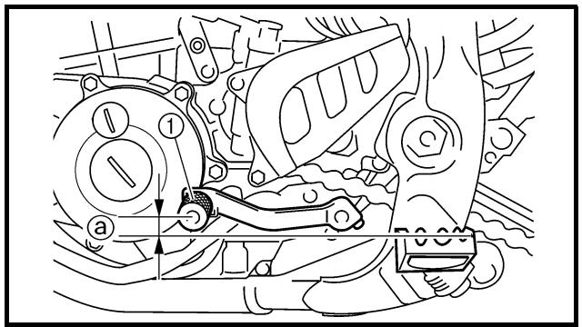
7. Install:
- Shaft ①
- Bearing ②
- Idle gear 2 ③
NOTE: \_\_\_\_
Apply the engine oil on the shaft, bearing and idle gear inner circumference.
8. Install:
- Dowel pin
- Gasket [crankcase cover (left)]
- Crankcase cover (left) ①
- Bolt [crankcase cover (left)]
10 Nm (1.0 m · kg, 7.2 ft · lb)
NOTE: \_\_\_\_
Tighten the bolts in stage, using a crisscross pattern.
9. Install:
- Plain washer
- Torque limiter ①
- Plain washer
NOTE:
Apply the engine oil to the shaft and plain washers.
10. Install:
- Cover (idle gear 1) ①
- Bolt ②
10 Nm (1.0 m · kg, 7.2 ft · lb)
NOTE: \_\_\_\_
Install the cover (idle gear 1) with its mark ⓐ facing upward.
11. Connect:
- AC magneto lead
Refer to “CABLE ROUTING DIAGRAM” section in the CHAPTER 2.
12. Install:
- Shift pedal ①
- Bolt (shift pedal)
12 Nm (1.2 m · kg, 8.7 ft · lb)
NOTE: \_\_\_\_
When installing the shift pedal onto the shift shaft, be sure that the center of the shift pedal is about 5.1 mm (0.2 in) @ above the top of the footrest.
7. Monter:
| Extent of removal | Order | Part name | Q'ty | Remarks |
| Preparation for removal | | ENGINE REMOVALHold the machine by placing the suitable stand under the frame.Drain the engine oilSeat, fuel tank and side coverRadiatorExhaust pipe and silencerAir cut-off valve assemblyClutch cable and guideShift pedalRear shock absorberCarburetor | | ⚠ WARNINGSupport the machine securely so there is no danger of it falling over.Refer to “ENGINE OIL REPLACEMENT” section in the CHAPTER 3.Refer to “SEAT, FUEL TANK AND SIDE COVERS” section.Refer to “RADIATOR” section.Refer to “EXHAUST PIPE AND SILENCER” section.Refer to “AIR INDUCTION SYSTEM” section.Disconnect at the engine side.Refer to “AC MAGNETO AND STARTER CLUTCH” section.Refer to “REAR SHOCK ABSORBER” section in the CHAPTER 6Refer to “CARBURETOR” section. |
DEPOSE DU MOTEUR
Extent of removal:
① Engine removal
| Extent of removal | Order | Part name | Q'ty | Remarks |
| | Cylinder head breather hoseIgnition coilDisconnect the AC magneto lead.Disconnect the starter motor lead.Negative battery lead | | Refer to “CAMSHAFTS” section.Refer to “ELECTRIC STARTING SYSTEM” section in the CHAPTER 6.Disconnect at the starter motor side. |
| 1 | 1 | Engine guard | 1 | Refer to “REMOVAL POINTS”. |
| 2 | Neutral switch | 1 |
| 3 | Chain cover | 1 |
| 4 | Nut (drive sprocket) | 1 |
| 5 | Lock washer | 1 |
| 6 | Drive sprocket | 1 |
| 7 | Clip | 1 |
| 8 | Bolt (brake pedal) | 1 |
| 9 | Brake pedal | 1 |
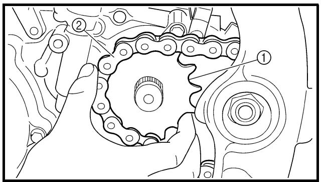
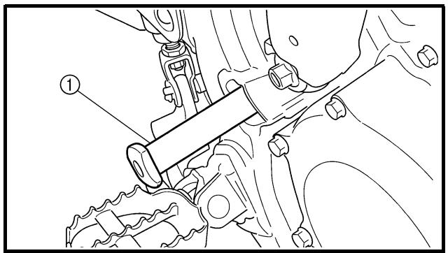
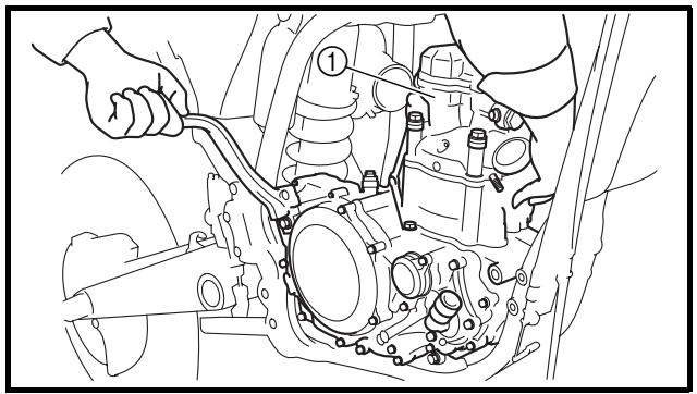
natural_image
Technical line drawing of a mechanical assembly with hands operating a component (no text or symbols visible)
EC4M3000
REMOVAL POINTS
EC4F3100
Drive sprocket
-
Remove:
-
Nut (drive sprocket) ①
- Lock washer ②
NOTE:
NOTE:
Remove the drive sprocket together with the drive chain.
EC4M3301
Engine removal
- Remove:
- Pivot shaft ①
NOTE:
If the pivot shaft is pulled all the way out, the swingarm will come loose. If possible, insert a shaft of similar diameter into the other side of the swingarm to support it.
- Remove:
- Engine ①
From right side.
NOTE:
Make sure that the couplers, hoses and cables are disconnected.
POINTS DE DEPOSE
Couronne arrière
- Déposer:
EC4M5000
ASSEMBLY AND INSTALLATION Engine installation
1. Install:
- Engine ①
Install the engine from right side.
- Pivot shaft ②
85 Nm (8.5 m · kg, 61 ft · lb)
- Engine mounting bolt (lower) ③
53 Nm (5.3 m · kg, 38 ft · lb)
- Engine lower bracket ④
- Bolt (engine lower bracket) ⑤
- Patch ⑥
• Engine mounting bolt (front) ⑦
53 Nm (5.3 m · kg, 38 ft · lb)
- Engine upper bracket (right) ⑧
• Engine upper bracket (left) ⑨
- Bolt (engine upper bracket) ⑩
55 Nm (5.5 m · kg, 40 ft · lb)
55 Nm (5.5 m · kg, 40 ft · lb)
• Engine mounting bolt (upper) ⑪
NOTE:
- Apply the molybdenum disulfide grease on the pivot shaft.
- Install the patch with the claw @ facing outside the chassis.

Brake pedal
1. Install:
- Spring ①
- Brake pedal ②
- O-ring ③ New
- Bolt (brake pedal) ④
26 Nm (2.6 m · kg, 19 ft · lb)
- Clip ⑤
NOTE:
Apply the lithium soap base grease on the bolt, O-rings and brake pedal bracket.
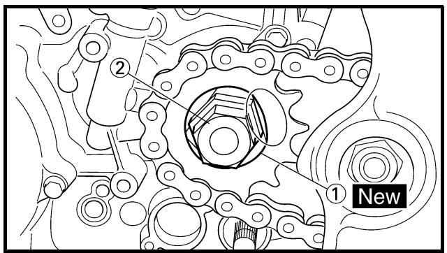
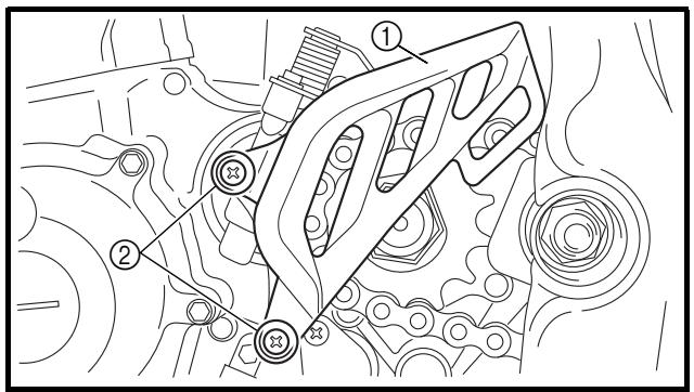
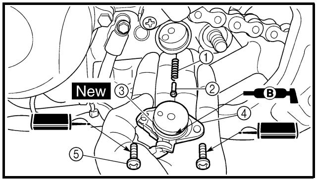
Drive sprocket
1. Install:
- Drive sprocket ①
- Drive chain ②
NOTE: ____
Install the drive sprocket together with the drive chain.
2. Install:
- Lock washer ① New
- Nut (drive sprocket) ②
Tighten the nut while applying the rear brake.
- Bend the lock washer tab to lock the nut.
4. Install:
- Chain guide
- Chain cover ①
- Screw (chain cover) ②
8 Nm (0.8 m · kg, 5.8 ft · lb)
5. Install:
- Spring ①
- Pin ②
- O-ring ③ New
- Neutral switch ④
- Screw (neutral switch) ⑤

4 Nm (0.4 m · kg, 2.9 ft · lb)
NOTE: ____
Apply the lithium soap base grease on the O-ring.
Couronne arrière
CRANKCASE AND CRANKSHAFT
CRANKCASE AND CRANKSHAFT
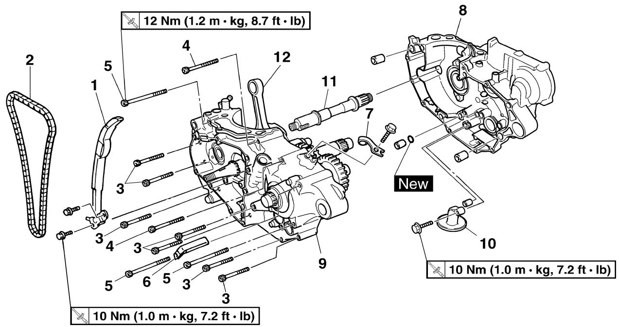
Extent of removal:
① Crankcase separation
② Crankshaft removal
| Extent of removal | Order | Part name | Q'ty | Remarks |
| Preparation for removal | | CRANKCASE SEPARATIONEnginePistonBalancerKick axle assemblySegmentStator | | Refer to “ENGINE REMOVAL” section.Refer to “CYLINDER AND PISTON” section.Refer to “BALANCER” section.Refer to “KICK AXLE AND SHIFT SHAFT” section.Refer to “AC MAGNETO AND STARTER CLUTCH” section. |
| 1 | Timing chain guide (rear) | 1 | |
| 2 | Timing chain | 1 |
| 3 | Bolt (50 mm) | 7 |
| 4 | Bolt (60 mm) | 2 |
| 5 | Bolt (80 mm) | 3 |
| 6 | Hose guide | 1 | Refer to “REMOVAL POINTS”. |
| 7 | Clutch cable holder | 1 |
| 8 | Crankcase (right) | 1 |
| 9 | Crankcase (left) | 1 |
Extent of removal:
① Crankcase bearing removal
| Extent of removal | Order | Part name | Q'ty | Remarks |
| Preparation for removal | | CRANKCASE BEARING REMOVALTransmissionShift cam and shift fork | | Refer to “TRANSMISSION, SHIFT CAM AND SHIFT FORK” section. |
| 1 | 1 | Oil seal | 3 | Refer to “REMOVAL POINTS”. |
| 2 | Bearing | 10 |
CARTER MOTEUR ET VILEBREQUIN KURBELGEHÄUSE UND KURBELWELLE CÁRTER Y CIGÜEÑAL
ROULEMENT DE CARTER MOTEUR
natural_image
Technical line drawing of a mechanical assembly with gears and housing (no text or symbols)
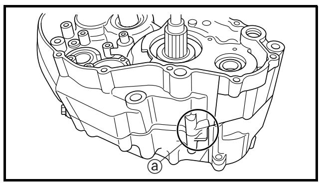
natural_image
Technical line drawing of a mechanical component with no visible text or symbols
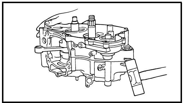
natural_image
Technical line drawing of a mechanical assembly with no visible text or symbols
REMOVAL POINTS
Crankcase
1. Separate:
- Crankcase (right)
- Crankcase (left)
Separation steps:
- Remove the crankcase bolts, hose guide and clutch cable holder.
NOTE:
Loosen each bolt 1/4 of a turn at a time and after all the bolts are loosened, remove them.
- Remove the crankcase (right).
NOTE:
- Place the crankcase with its left side downward and split it by inserting a screw-driver tip into the splitting slit ⓐ in the crankcase.
- Lift the crankcase (right) horizontally while lightly patting the case splitting slit and engine mounting boss using a soft hammer, and leave the crankshaft and transmission with the crankcase (left).
CAUTION:
Use soft hammer to tap on the case half. Tap only on reinforced portions of case. Do not tap on gasket mating surface. Work slowly and carefully. Make sure the case halves separate evenly. If the cases do not separate, check for a remaining case screw or fitting. Do not force.
- Remove the dowel pins and O-ring.
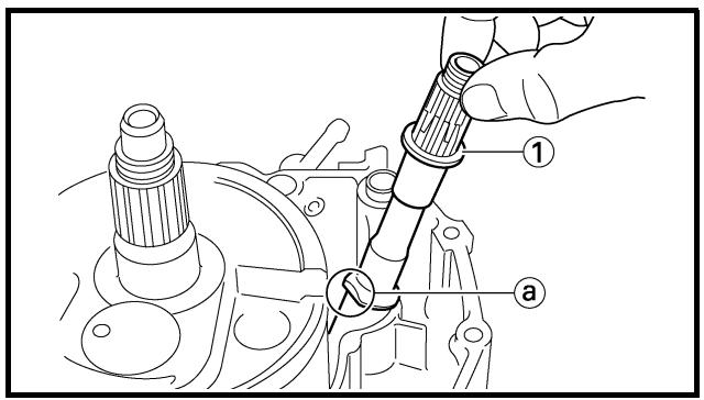
Balancer shaft
1. Remove:
- Balancer shaft ①
NOTE:
Remove the balancer shaft with its flat side ⓐ facing the crankshaft.
POINTS DE DEPOSE
Carter moteur
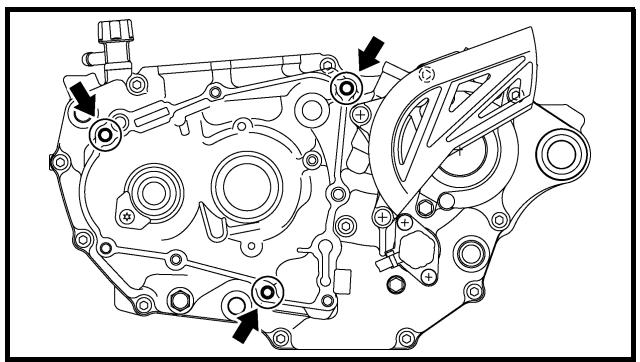
natural_image
Technical line drawing of a mechanical assembly with no visible text or symbols
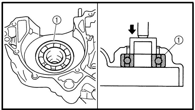
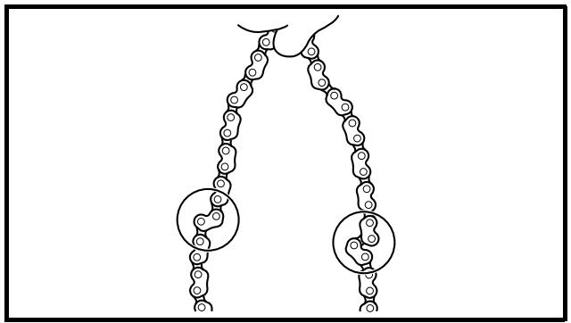
natural_image
Diagram of a mechanical linkage or chain structure with two circular components, no text or symbols present
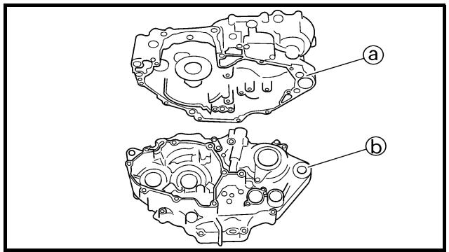
Crankshaft
1. Remove:
- Crankshaft ①
Use the crankcase separating tool ②.
Crankcase separating tool: YU-A9642/90890-04152
CAUTION:
Do not use a hammer to drive out the crankshaft.
Crankshaft bearing
1. Remove:
- Bearing ①
NOTE:
- Remove the bearing from the crankcase by pressing its inner race.
- Do not use the removed bearing.
INSPECTION
Timing chain and timing chain guide
1. Inspect:
- Timing chain
Cracks/stiff → Replace the timing chain and camshaft sprocket as a set.
2. Inspect:
- Timing chain guide
Wear/damage → Replace.
EC4N4101
Crankcase
1. Inspect:
- Contacting surface ⓐ
Scratches → Replace.
- Engine mounting boss ⓑ, crankcase
Cracks/damage → Replace.
CARTER MOTEUR ET VILEBREQUIN KURBELGEHÄUSE UND KURBELWELLE CÁRTER Y CIGÜEÑAL
ENG

Vilebrequin
- Déposer:
- Bearing
Rotate inner race with a finger.
Rough spot/seizure → Replace.
3. Inspect:
- Oil seal
Wear/damage → Replace.
EC4N4201
Crankshaft
1. Measure:
- Runout limit ⓐ
- Small end free play limit ⓑ
- Connecting rod big end side clearance ©
- Crank width ⓓ
Out of specification → Replace.
Use the dial gauge and a thickness gauge.
| Dial gauge and stand:YU-3097/90890-01252 |
| Standard | |
| Runout limit: | 0.03 mm(0.0012 in) | 0.05 mm(0.002 in) |
| Small end free play: | 0.4 ~ 1.0 mm(0.016 ~ 0.039 in) | 2.0 mm(0.08 in) |
| Side clearance: | 0.15 ~ 0.45 mm(0.0059 ~ 0.0177 in) | 0.50 mm(0.02 in) |
| Crack width: | 61.95 ~ 62.00 mm(2.439 ~ 2.441 in) | — |
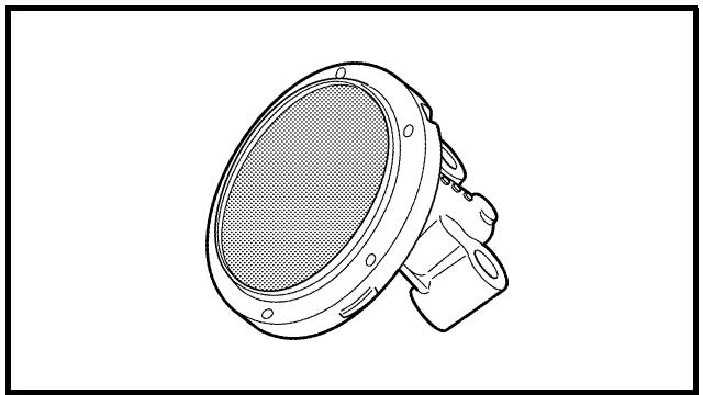
natural_image
Technical line drawing of a mechanical component with a circular housing and mounting bracket (no text or symbols)
Oil strainer
1. Inspect:
- Oil strainer
Damage → Replace.
CARTER MOTEUR ET VILEBREQUIN KURBELGEHÄUSE UND KURBELWELLE CÁRTER Y CIGÜEÑAL
ENG

2. Contrôler:
EC4N5000
ASSEMBLY AND INSTALLATION
Crankshaft bearing
1. Install:
- Bearing New
- Bearing stopper
- Bolt (bearing stopper)

10 Nm (1.0 m · kg, 7.2 ft · lb)
- Screw (bearing stopper)

10 Nm (1.0 m · kg, 7.2 ft · lb)
- Screw [bearing stopper (crankshaft)] ①
14 Nm (1.4 m · kg, 10 ft · lb)
To crankcase (left and right).
NOTE:
- Install the bearing by pressing its outer race parallel.
- To prevent the screw [bearing stopper (crankshaft)] from becoming loose, crush the screw head periphery ⓐ into the concave ⓑ using a punch etc. In so doing, take care not to damage the screwdriver receiving hole in the screw head.
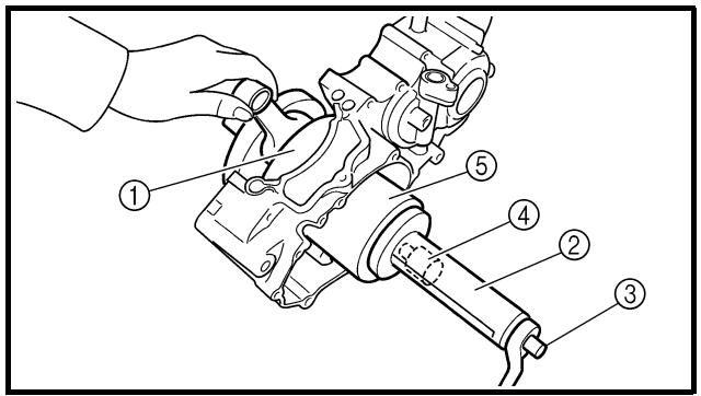
Crankshaft
1. Install:
- Crankshaft ①
Use the crankshaft installing tool ②, ③, ④ and ⑤.
Crankshaft installing pot ②:
YU-90050/90890-01274
Crankshaft installing bolt ③:
YU-90050/90890-01275
Adaptor (M12) ④:
YU-90063/90890-01278
Spacer (crankshaft installer) ⑤:
YM-91044/90890-04081
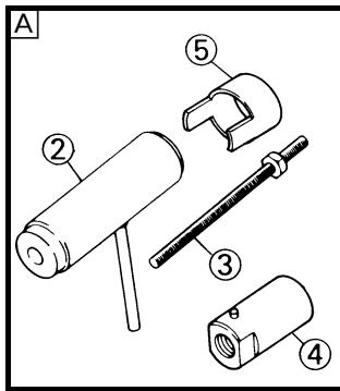
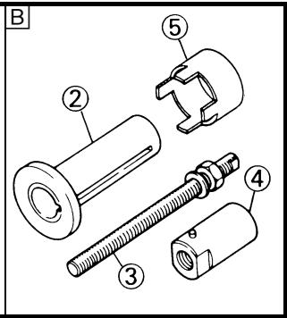
A For USA and CDN
B Except for USA and CDN
CARTER MOTEUR ET VILEBREQUIN KURBELGEHÄUSE UND KURBELWELLE CÁRTER Y CIGÜEÑAL
ENG

ASSEMBLAGE ET MONTAGE Roulement de vilebrequin
- Hold the connecting rod at top dead center with one hand while turning the nut of the installing tool with the other. Operate the installing tool until the crankshaft bottoms against the bearing.
- Before installing the crankshaft, clean the contacting surface of crankcase.
CAUTION:
Do not use a hammer to drive in the crankshaft.
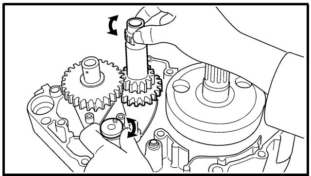
natural_image
Mechanical assembly diagram showing gear and shaft components (no text or labels)
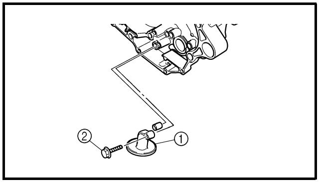
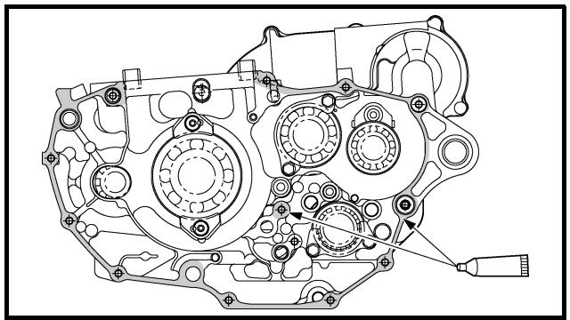
natural_image
Technical line drawing of an automotive gear assembly (no text or labels)
2. Check:
- Shifter operation
- Transmission operation
Unsmooth operation → Repair.
3. Install:
- Oil strainer ①
- Bolt (oil strainer) ②
10 Nm (1.0 m · kg, 7.2 ft · lb)
4. Apply:
- Sealant
On the crankcase (right).

YAMAHA Bond No. 1215
(ThreeBond® No. 1215):
90890-85505
NOTE:
Clean the contacting surface of crankcase (left and right) before applying the sealant.
CARTER MOTEUR ET VILEBREQUIN KURBELGEHÄUSE UND KURBELWELLE CÁRTER Y CIGÜEÑAL
ENG

N.B.:
5. Install:
- Dowel pin ①
- O-ring ② New
- Crankcase (right)
To crankcase (left).
NOTE:
- Fit the crankcase (right) onto the crankcase (left). Tap lightly on the case with soft hammer.
- When installing the crankcase, the connecting rod should be positioned at TDC (top dead center).
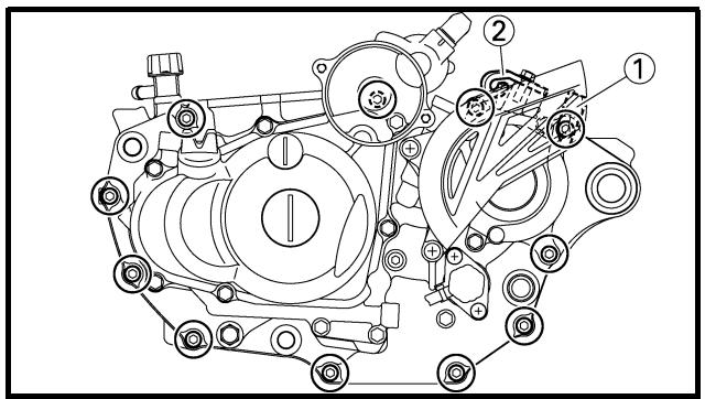
6. Tighten:
- Hose guide ①
- Clutch cable holder ②
- Bolt (clutch cable holder)
10 Nm (1.0 m · kg, 7.2 ft · lb)
- Bolt (crankcase)
12 Nm (1.2 m · kg, 8.7 ft · lb)
NOTE:
Tighten the crankcase tightening bolts in stage, using a crisscross pattern.
7. Install:
- Timing chain
- Timing chain guide (rear)
- Bolt (timing chain guide)
10 Nm (1.0 m · kg, 7.2 ft · lb)
8. Remove:
- Sealant
Forced out on the cylinder mating surface.
9. Apply:
- Engine oil
To the crank pin, bearing and oil delivery hole.
10. Check:
- Crankshaft and transmission operation.
Unsmooth operation → Repair.
CARTER MOTEUR ET VILEBREQUIN KURBELGEHÄUSE UND KURBELWELLE CÁRTER Y CIGÜEÑAL
5. Monter:
TRANSMISSION, SHIFT CAM AND SHIFT FORK
TRANSMISSION, SHIFT CAM AND SHIFT FORK
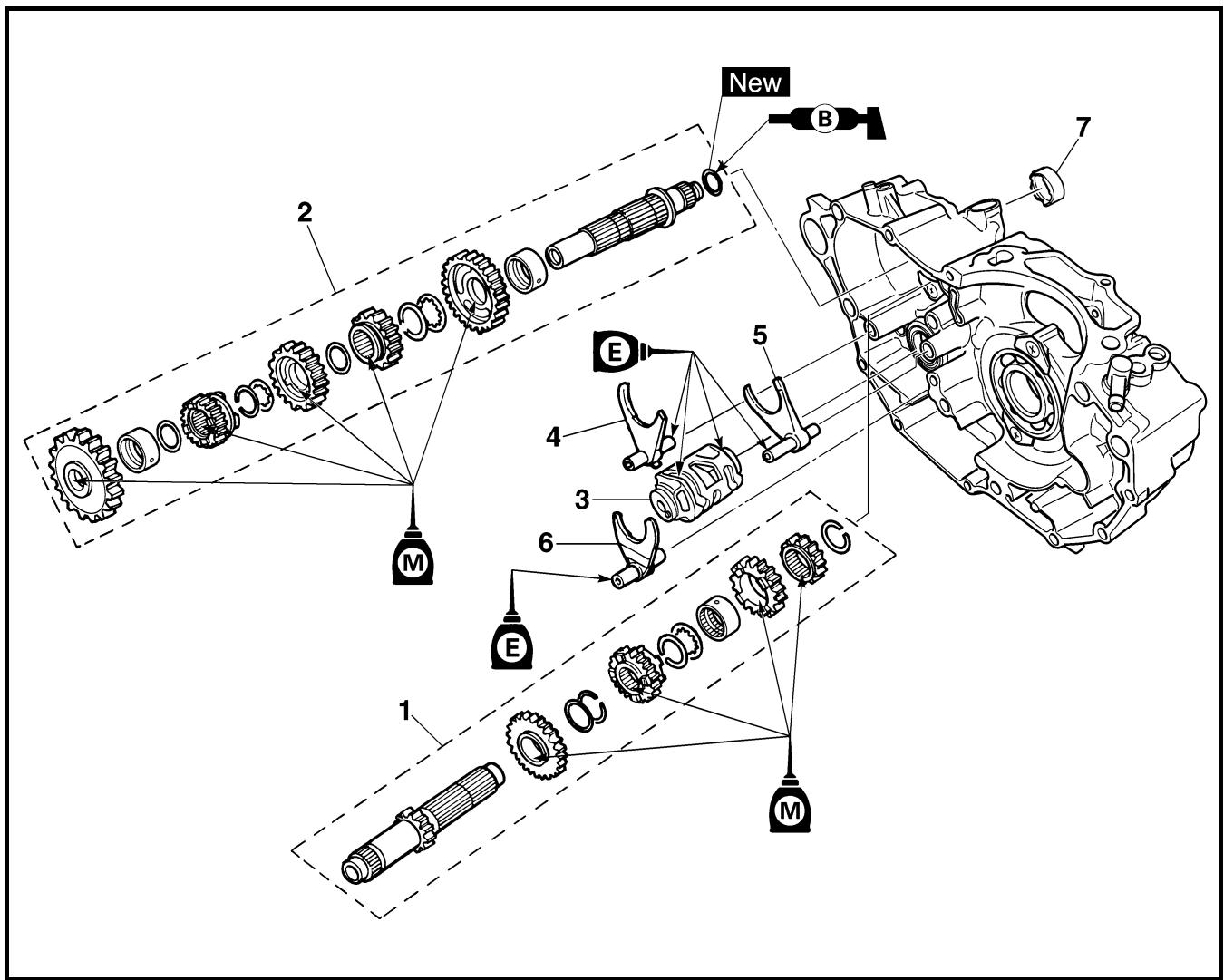
Extent of removal:
① Shift fork, shift cam, main axle and drive axle removal
| Extent of removal | Order | Part name | Q'ty | Remarks |
| Preparation for removal | | TRANSMISSION, SHIFT CAM AND SHIFT FORK REMOVALEngineSeparate the crankcase. | | Refer to “ENGINE REMOVAL” section.Refer to “CRANKCASE AND CRANK-SHAFT” section. |
| 1 | 1 | Main axle | 1 | Refer to “REMOVAL POINTS”. |
| 2 | Drive axle | 1 |
| 3 | Shift cam | 1 |
| 4 | Shift fork 3 | 1 |
| 5 | Shift fork 2 | 1 |
| 6 | Shift fork 1 | 1 |
| 7 | Collar | 1 |
BOITE DE VITESSES, TAMBOUR ET FOURCHETTES DE SELECTION GETRIEBE, SCHALTWALZE UND SCHALTGABELN CAJA DE CAMBIOS, LEVA DE CAMBIO Y HORQUILLA DE CAMBIO
BOITE DE VITESSES, TAMBOUR ET FOURCHETTES DE SELECTION
BOITE DE VITESSES, TAMBOUR ET FOURCHETTES DE SELECTION
EC4H3000
REMOVAL POINTS
Shift fork, shaft cam and transmission
1. Remove:
- Main axle ①
- Drive axle ②
- Shift cam
- Shift fork 3
- Shift fork 2
- Shift fork 1
NOTE:
- Remove assembly with the collar ③ installed to the crankcase.
- Remove assembly carefully. Note the position of each part. Pay particular attention to the location and direction of shift forks.
- Remove the main axle, drive axle, shift cam and shift fork all together by tapping lightly on the transmission drive axle with a soft hammer.
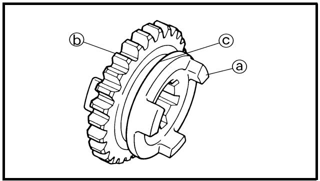
EC4H4000
INSPECTION
EC4H4200
Gears
1. Inspect:
- Matching dog ⓐ
- Gear teeth ⓑ
- Shift fork groove ©
Wear/damage → Replace.
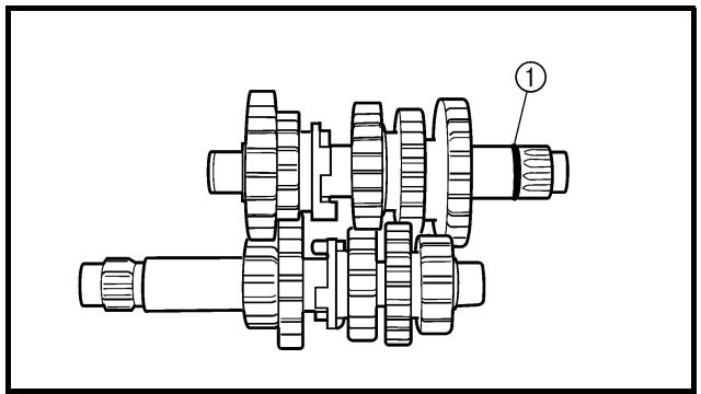
natural_image
Technical line drawing of a mechanical gear assembly with no visible text or symbols
2. Inspect:
- O-ring ①
Damage → Replace.
3. Check:
- Gears movement
Unsmooth movement → Repair or replace.
BOITE DE VITESSES, TAMBOUR ET FOURCHETTES DE SELECTION GETRIEBE, SCHALTWALZE UND SCHALTGABELN CAJA DE CAMBIOS, LEVA DE CAMBIO Y HORQUILLA DE CAMBIO
POINTS DE DEPOSE
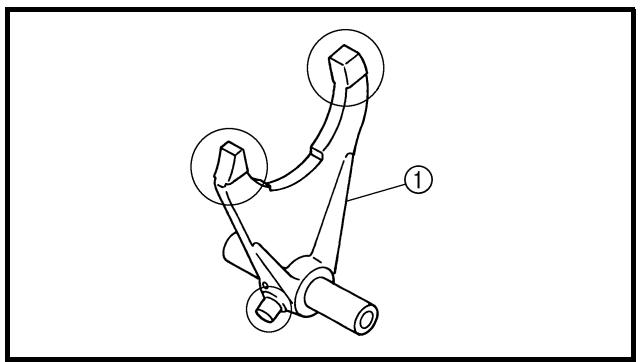
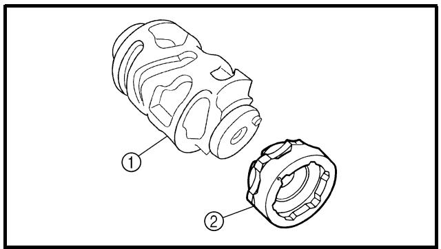
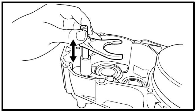
natural_image
Technical line drawing of a mechanical component being adjusted for assembly (no text or symbols)
EC4H4600
Bearing
1. Inspect:
- Bearing ①
Rotate inner race with a finger.
Rough spot/seizure → Replace.
EC4H4801
Shift fork, shift cam and segment
1. Inspect:
- Shift fork ①
Wear/damage/scratches → Replace.
2. Inspect:
- Shift cam ①
- Segment ②
Bend/wear/damage → Replace.
3. Check:
- Shift fork movement
Unsmooth operation → Replace shift fork.
NOTE:
For a malfunctioning shift fork, replace not only the shift fork itself but the two gears each adjacent to the shift fork.
BOITE DE VITESSES, TAMBOUR ET FOURCHETTES DE SELECTION GETRIEBE, SCHALTWALZE UND SCHALTGABELN CAJA DE CAMBIOS, LEVA DE CAMBIO Y HORQUILLA DE CAMBIO
Roulement
- Contrôler:
- Roulement ①
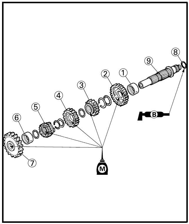
ASSEMBLY AND INSTALLATION Transmission
1. Install:
- 5th pinion gear (25T) ①
- 3rd pinion gear (16T) ②
- Collar ③
• 4th pinion gear (20T) ④
- 2nd pinion gear (15T) ⑤
To main axle ⑥.
NOTE:
Apply the molybdenum disulfide oil on the inner and end surface of the idler gear and on the inner surface of the sliding gear, then install.
2. Install:
- Collar ①
- 2nd wheel gear (26T) ②
- 4th wheel gear (21T) ③
- 3rd wheel gear (21T) ④
- 5th wheel gear (21T) ⑤
- Collar ⑥
- 1st wheel gear (29T) ⑦
- O-ring ⑧
To drive axle ⑨.
NOTE:
- Apply the molybdenum disulfide oil on the inner and end surface of the idler gear and on the inner surface of the sliding gear, then install.
- Apply the lithium soap base grease on the O-ring.
BOITE DE VITESSES, TAMBOUR ET FOURCHETTES DE SELECTION GETRIEBE, SCHALTWALZE UND SCHALTGABELN CAJA DE CAMBIOS, LEVA DE CAMBIO Y HORQUILLA DE CAMBIO
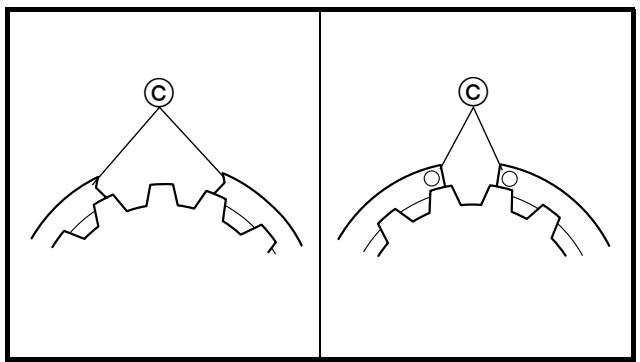
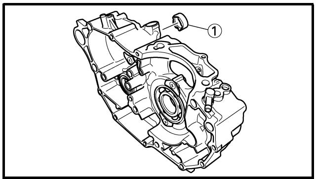
natural_image
Technical line drawing of a mechanical component with labeled parts (no text or symbols present)
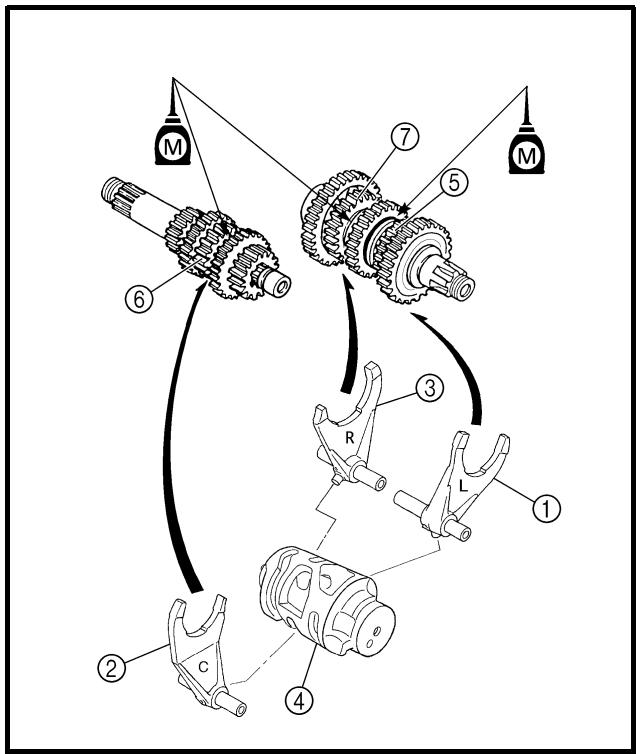
flowchart
graph TD
    A["Component 1"] --> B["Component 2"]
    B --> C["Component 3"]
    C --> D["Component 4"]
    D --> E["Component 5"]
    E --> F["Component 6"]
    F --> G["Component 7"]
    G --> H["Component 8"]
    H --> I["Component 9"]
    I --> J["Component 10"]
    style A fill:#f9f,stroke:#333
    style B fill:#f9f,stroke:#333
    style C fill:#f9f,stroke:#333
    style D fill:#f9f,stroke:#333
    style E fill:#f9f,stroke:#333
    style F fill:#f9f,stroke:#333
    style G fill:#f9f,stroke:#333
    style H fill:#f9f,stroke:#333
    style I fill:#f9f,stroke:#333
    style J fill:#f9f,stroke:#333
3. Install:
- Plain washer ①
- Circlip ② New
NOTE:
- Be sure the circlip sharp-edged corner ⓐ is positioned opposite side to the plain washer and gear ⓑ.
- Install the circlip with its ends © settled evenly on the spline crests.
4. Install:
- Collar ①
NOTE:
- Apply the lithium soap base grease on the oil seal lip.
- When installing the spacer into the crankcase, pay careful attention to the crankcase oil seal lip.
5. Install:
- Shift fork 1 (L) ①
- Shift fork 2 (C) ②
- Shift fork 3 (R) ③
- Shift cam ④
To main axle and drive axle.
NOTE:
- Apply the molybdenum disulfide oil on the shift fork grooves.
- Mesh the shift fork #1 (L) with the 4th wheel gear ⑤ and #3 (R) with the 5th wheel gear ⑦ on the drive axle.
- Mesh the shift fork #2 (C) with the 3rd pinion gear ⑥ on the main axle.
BOITE DE VITESSES, TAMBOUR ET FOURCHETTES DE SELECTION GETRIEBE, SCHALTWALZE UND SCHALTGABELN CAJA DE CAMBIOS, LEVA DE CAMBIO Y HORQUILLA DE CAMBIO
3. Monter:
• Rondelle pleine ①
- Circlip ② New
- Circlip ② New
N.B.:
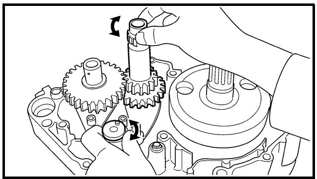
natural_image
Mechanical gear assembly diagram showing gear meshing and shaft alignment (no text or labels)
6. Install:
- Transmission assembly ①
To crankcase (left) ②.
NOTE:
Apply the engine oil on the bearings and guide bars.
7. Check:
- Shifter operation
• Transmission operation
Unsmooth operation → Repair.
BOITE DE VITESSES, TAMBOUR ET FOURCHETTES DE SELECTION GETRIEBE, SCHALTWALZE UND SCHALTGABELN CAJA DE CAMBIOS, LEVA DE CAMBIO Y HORQUILLA DE CAMBIO

6. Monter:
① Front wheel removal
③ Brake disc removal
② Wheel bearing removal
| Extent of removal | Order | Part name | Q'ty | Remarks |
| Preparation for removal | | FRONT WHEEL REMOVALHold the machine by placing the suitable stand under the engine. | | WARNINGSupport the machine securely so there is no danger of it falling over. |
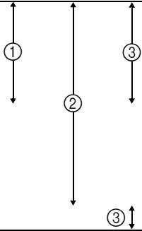 | | 1 | Bolt (axle holder) | 4 | Only loosening. |
| 2 | Nut (front wheel axle) | 1 |
| 3 | Front wheel axle | 1 |
| 4 | Front wheel | 1 |
| 5 | Speed sensor | 1 |
| 6 | Collar | 1 |
| 7 | Oil seal | 1 |
| 8 | Bearing | 2 | Refer to “REMOVAL POINTS”. |
| 9 | Brake disc | 1 |
CHASSIS
ROUE AVANT ET ROUE ARRIERE
ROUE AVANT
Extent of removal:
① Rear wheel removal
③ Brake disc removal
② Wheel bearing removal
| Extent of removal | Order | Part name | Q'ty | Remarks |
| Preparation for removal | | REAR WHEEL REMOVALHold the machine by placing the suitable stand under the engine. | | WARNINGSupport the machine securely so there is no danger of it falling over. |
| 1323 | 1 | Nut (rear wheel axle) | 1 | Refer to “REMOVAL POINTS”. |
| 2 | Rear wheel axle | 1 |
| 3 | Chain puller | 2 |
| 4 | Rear wheel | 1 |
| 5 | Collar | 2 |
| 6 | Driven sprocket | 1 |
| 7 | Oil seal | 2 |
| 8 | Circlip | 1 |
| 9 | Bearing | 2 | Refer to “REMOVAL POINTS”. |
| 10 | Brake disc | 1 |
ROUE AVANT ET ROUE ARRIERE
VORDER- UND HINTERRAD
RUEDA DELANTERA Y RUEDA TRASERA
CHAS

ROUE ARRIERE
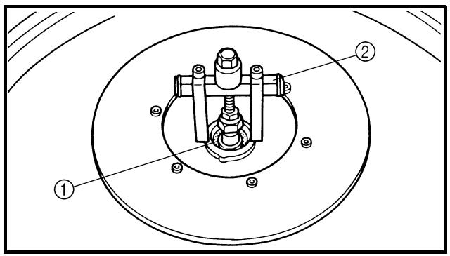
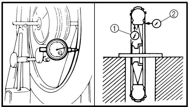
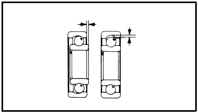
natural_image
Technical diagram of two mechanical bearing assemblies with alignment arrows (no text or labels)
EC593000
REMOVAL POINTS
EC523101
Rear wheel
- Remove:
- Wheel ①
NOTE:
Push the wheel forward and remove the drive chain ②.
EC513201
Wheel bearing (if necessary)
- Remove:
- Bearing ①
NOTE:
Remove the bearing using a general bearing puller ②.
EC594000
INSPECTION
EC514100
Wheel
- Measure:
- Wheel runout
Out of limit → Repair/replace.

Wheel runout limit:
Radial ①: 2.0 mm (0.08 in)
Lateral ②: 2.0 mm (0.08 in)
- Inspect:
- Bearing
Rotate inner race with a finger.
Rough spot/seizure → Replace.
NOTE:
Replace the bearings, oil seal and wheel collar as a set.
POINTS DE DEPOSE
Roue arrière
- Déposer:
- Roue ①
N.B.:
EC514200
Wheel axle
1. Measure:
- Wheel axle bends
Out of specification → Replace.
Use the dial gauge ①.

Wheel axle bending limit: 0.5 mm (0.020 in)
NOTE:
The bending value is shown by one half of the dial gauge reading.

WARNING
Do not attempt to straighten a bent axle.
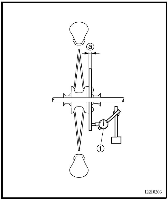
EC594200
Brake disc
1. Measure:
- Brake disc deflection (only rear brake disc)
Use the dial gauge ①.
Out of specification → Inspect wheel runout.
If wheel runout is in good condition, replace the brake disc.
| Disc deflection limit: |
| Standard | |
| Rear | — | 0.15 mm(0.006 in) |
2. Measure:
- Brake disc thickness ⓐ
Out of limit → Replace.
 | Disc wear limit: |
| Standard | |
| Front | 3.0 mm (0.12 in) | 2.5 mm (0.10 in) |
| Rear | 4.0 mm (0.16 in) | 3.5 mm (0.14 in) |
ROUE AVANT ET ROUE ARRIERE
VORDER- UND HINTERRAD
RUEDA DELANTERA Y RUEDA TRASERA
CHAS

Axe de roue
1. Mesurer:
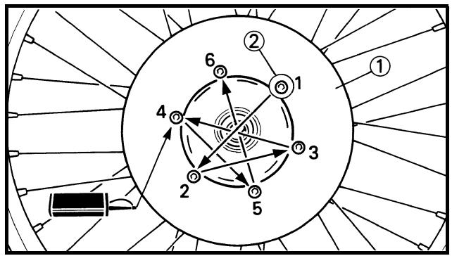
flowchart
graph TD
    1["①"] --> 2["②"]
    2 --> 3["③"]
    3 --> 4["④"]
    4 --> 5["⑤"]
    5 --> 6["⑥"]
    6 --> 1
    style 1 fill:#f9f,stroke:#333
    style 2 fill:#f9f,stroke:#333
    style 3 fill:#f9f,stroke:#333
    style 4 fill:#f9f,stroke:#333
    style 5 fill:#f9f,stroke:#333
    style 6 fill:#f9f,stroke:#333
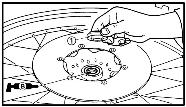
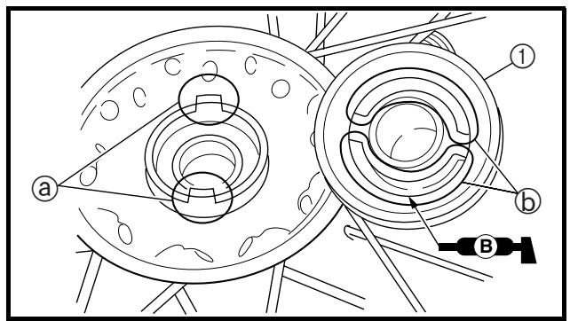
EC595000
ASSEMBLY AND INSTALLATION
Front wheel
-
Install:
-
Bearing (left) ①
- Spacer ②
- Bearing (right) ③
- Oil seal ④ New
NOTE:
- Apply the lithium soap base grease on the bearing and oil seal lip when installing.
- Use a socket that matches the outside diameter of the race of the bearing.
- Left side of bearing shall be installed first.
- Install the oil seal with its manufacture's marks or numbers facing outward.
CAUTION:
Do not strike the inner race of the bearing. Contact should be made only with the outer race.
-
Install:
-
Brake disc ①
- Bolt (brake disc) ②

12 Nm (1.2 m · kg, 8.7 ft · lb)
NOTE:
Tighten the bolts in stage, using a crisscross pattern.
- Install:
- Collar ①
NOTE:
Apply the lithium soap base grease on the oil seal lip.
- Install:
- Speed sensor ①
NOTE:
- Apply the lithium soap base grease on the oil seal lip of the speed sensor.
- Make sure the two projections ⓐ in the wheel hub are meshed with the two slots ⓑ in the speed sensor.
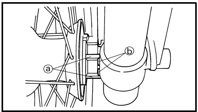
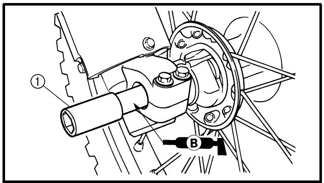
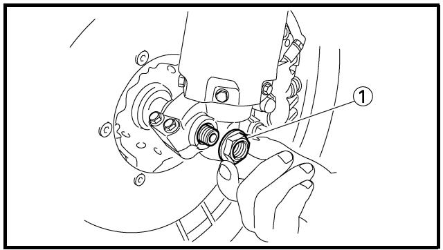
5. Install:
- Wheel
NOTE:
- Install the brake disc ① between the brake pads ② correctly.
- Make sure that the projections ⓐ in the speed sensor fits over the stopper ⓑ on the front fork inner tube.
6. Install:
- Wheel axle ①
NOTE:
Apply the lithium soap base grease on the wheel axle.
7. Install:
- Nut (wheel axle) ①

90 Nm (9.0 m · kg, 65 ft · lb)
ROUE AVANT ET ROUE ARRIERE VORDER- UND HINTERRAD RUEDA DELANTERA Y RUEDA TRASERA

5. Monter:
- Roue
N.B.:
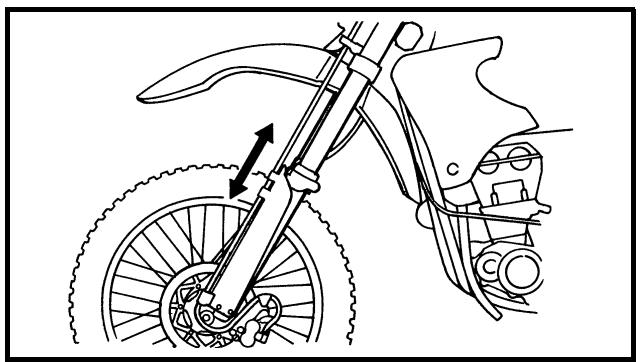
natural_image
Line drawing of a motorcycle's front wheel and side-mounted gear assembly (no text or symbols)
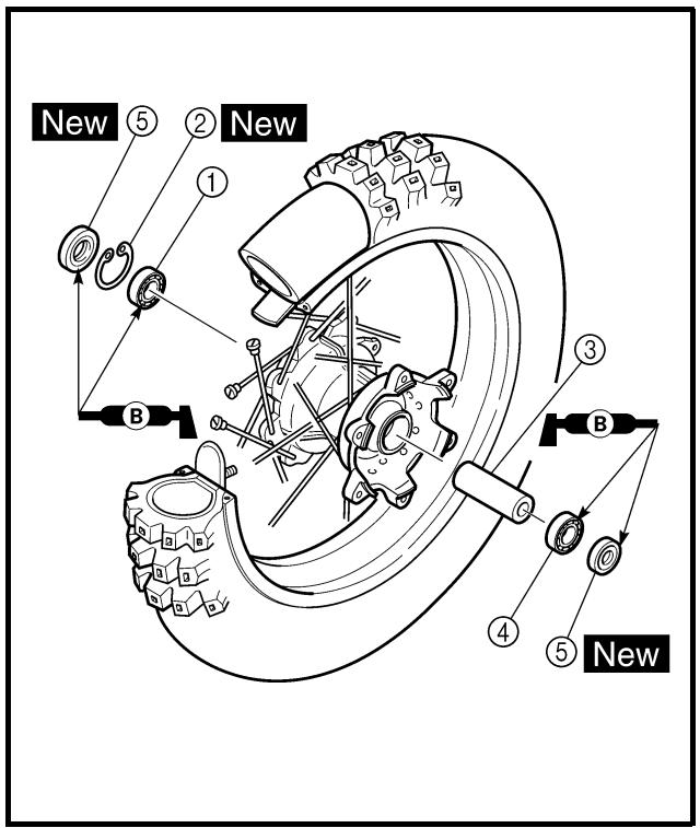
8. Tighten:
- Bolt (axle holder) ①
23 Nm (2.3 m · kg, 17 ft · lb)
NOTE:
Before tightening the bolt, fit the wheel axle to the axle holder by stroking the front fork several times with the front brake applied.
Rear wheel
1. Install:
- Bearing (right) ①
- Circlip ② New
- Spacer ③
- Bearing (left) ④
- Oil seal ⑤ New
NOTE:
- Apply the lithium soap base grease on the bearing and oil seal lip when installing.
• Install the bearing with seal facing outward.
- Use a socket that matches the outside diameter of the race of the bearing.
- Right side of bearing shall be installed first.
- Install the oil seal with its manufacture's marks or numbers facing outward.
CAUTION:
Do not strike the inner race of the bearing. Contact should be made only with the outer race.
8. Serrer:
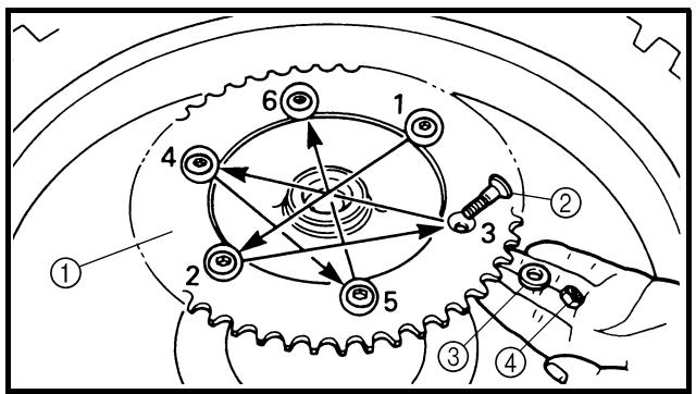
flowchart
graph TD
    A["1"] --> B["2"]
    B --> C["3"]
    C --> D["4"]
    D --> E["5"]
    E --> F["6"]
    F --> A
    style A fill:#f9f,stroke:#333
    style B fill:#f9f,stroke:#333
    style C fill:#f9f,stroke:#333
    style D fill:#f9f,stroke:#333
    style E fill:#f9f,stroke:#333
    style F fill:#f9f,stroke:#333
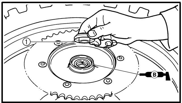
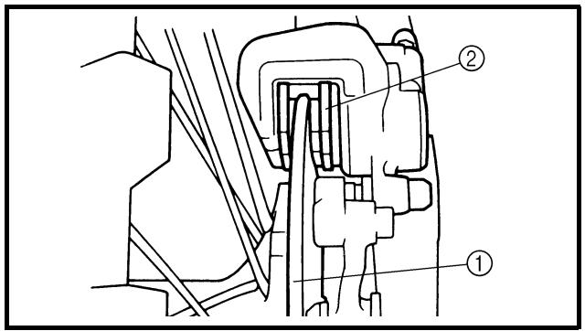
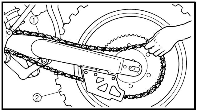
2. Install:
- Brake disc ①
- Bolt (brake disc) ②

14 Nm (1.4 m · kg, 10 ft · lb)
NOTE:
Tighten the bolts in stage, using a crisscross pattern.
3. Install:
- Driven sprocket ①
- Bolt (driven sprocket) ②
- Plain washer (driven sprocket) ③
- Nut (driven sprocket) ④
50 Nm (5.0 m · kg, 36 ft · lb)
NOTE:
Tighten the nuts in stage, using a crisscross pattern.
4. Install:
- Collar ①
NOTE:
Apply the lithium soap base grease on the oil seal lip.
5. Install:
- Wheel
NOTE:
Install the brake disc ① between the brake pads ② correctly.
6. Install:
- Drive chain ①
NOTE:
Push the wheel ② forward and install the drive chain.
ROUE AVANT ET ROUE ARRIERE VORDER- UND HINTERRAD RUEDA DELANTERA Y RUEDA TRASERA

2. Monter:
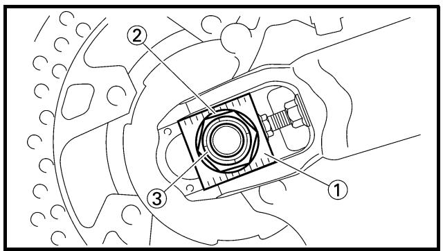
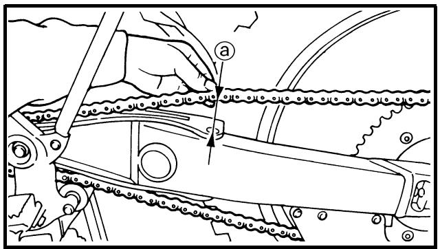
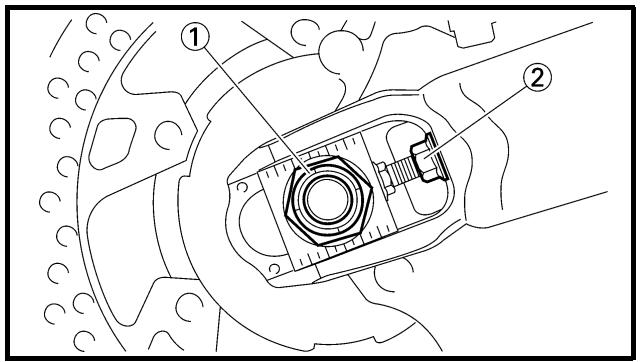
7. Install:
- Chain puller (left) ①
- Wheel axle ②
NOTE:
- Install the chain puller (left), and insert the wheel axle from left side.
- Apply the lithium soap base grease on the wheel axle.
8. Install:
- Chain puller (right) ①
- Plain washer ②
- Nut (wheel axle) ③
NOTE:
Temporarily tighten the nut (wheel axle) at this point.
9. Adjust:
- Drive chain slack ⓐ

Drive chain slack:
48 \~ 58 mm (1.9 \~ 2.3 in)
Refer to "DRIVE CHAIN SLACK ADJUSTMENT" section in the CHAPTER 3.
10. Tighten:
- Nut (wheel axle) ①
125 Nm (12.5 m · kg, 90 ft · lb)
- Locknut ②
19 Nm (1.9 m · kg, 13 ft · lb)
ROUE AVANT ET ROUE ARRIERE VORDER- UND HINTERRAD RUEDA DELANTERA Y RUEDA TRASERA

7. Monter:
① Brake hose removal
③ Master cylinder removal
② Caliper removal
| Extent of removal | Order | Part name | Q'ty | Remarks |
| Preparation for removal | | FRONT BRAKE REMOVALHold the machine by placing the suitable stand under the engine.Drain the brake fluid. | | WARNINGSupport the machine securely so there is no danger of it falling over.Refer to “REMOVAL POINTS”. |
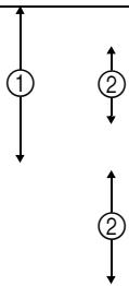 | 3↑ | 1 | Brake hose holder (protector) | 2 | Remove when loosening the pad pin.Loosen when disassembling the caliper. |
| 2 | Brake hose holder (caliper) | 1 |
| 3 | Union bolt | 2 |
| 4 | Brake hose | 1 |
| 5 | Pad pin plug | 1 |
| 6 | Pad pin | 1 |
| 7 | Caliper | 1 |
| 8 | Brake lever | 1 |
| 9 | Master cylinder bracket | 1 |
| 10 | Master cylinder | 1 |
FREIN AVANT ET FREIN ARRIERE
FREIN AVANT
Extent of removal:
① Master cylinder removal
③ Caliper removal
② Brake hose removal
| Extent of removal | Order | Part name | Q'ty | Remarks |
| Preparation for removal | | REAR BRAKE REMOVALHold the machine by placing the suitable stand under the engine.Rear wheelDrain the brake fluid. | | WARNINGSupport the machine securely so there is no danger of it falling over.Refer to “FRONT WHEEL AND REAR WHEEL” section.Refer to “REMOVAL POINTS”. |
| 1↓1↑23↓3 | 1 | Brake pedal | 1 | |
| 2 | Master cylinder | 1 | |
| 3 | Brake hose holder | 2 | |
| 4 | Union bolt | 2 | |
| 5 | Brake hose | 1 | |
| 6 | Pad pin plug | 1 | Remove when loosening the pad pin.Loosen when disassembling the caliper. |
| 7 | Pad pin | 1 |
| 8 | Caliper | 1 |
FREIN AVANT ET FREIN ARRIERE VORDER- UND HINTERRADBREMSEN FRENO DELANTERO Y FRENO TRASERO
FREIN ARRIERE
A Front
B Rear
Extent of removal:
① Front caliper disassembly
② Rear caliper disassembly
| Extent of removal | Order | Part name | Q'ty | Remarks |
| | | CALIPER DISASSEMBLY | A | B | |
| 1 | Pad pin | 1 | 1 |
| 2 | Brake pad | 2 | 2 |
| 3 | Pad support | 1 | 1 |
| 4 | Caliper piston | 2 | 1 |
| 5 | Dust seal | 2 | 1 | Refer to “REMOVAL POINTS”. |
| 6 | Piston seal | 2 | 1 |
FREIN AVANT ET FREIN ARRIERE VORDER- UND HINTERRADBREMSEN FRENO DELANTERO Y FRENO TRASERO
DEMONTAGE DE L'ETRIER DE FREIN
A Avant
B Arrière
A Front
B Rear
Extent of removal:
① Front master cylinder disassembly
② Rear master cylinder disassembly
| Extent of removal | Order | Part name | Q'ty | Remarks |
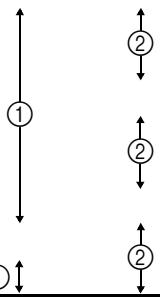 1 1 | 12345678 | MASTER CYLINDER DISASSEMBLYMaster cylinder capDiaphragmReservoir floatMaster cylinder bootCirclipPlain washerPush rodMaster cylinder kit | 1111111111111111111111111111111111111111111111111111111111111111111111111111111111111111111111111111 | Use a long nose circlip pliers. |
FREIN AVANT ET FREIN ARRIERE VORDER- UND HINTERRADBREMSEN FRENO DELANTERO Y FRENO TRASERO
DEMONTAGE DU MAITRE-CYLINDRE DE FREIN
A Avant
B Arrière
natural_image
Line drawing of a hand using a tool to adjust or install a mechanical component (no text or symbols present)
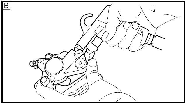
natural_image
Line drawing of hands using a pliers to handle a mechanical component (no text or symbols)
EC5A3000
REMOVAL POINTS
Brake fluid
- Remove:
[Front]
- Master cylinder cap ①
[Rear]
- Master cylinder cap ①
- Protector
NOTE:
Do not remove the diaphragm.
A Front
B Rear
- Connect the transparent hose ② to the bleed screw ① and place a suitable container under its end.
A Front
B Rear
- Loosen the bleed screw and drain the brake fluid while pulling the lever in or pushing down on the pedal.
CAUTION:
- Do not reuse the drained brake fluid.
- Brake fluid may erode painted surfaces or plastic parts. Always clean up spilled fluid immediately.
EC533301
Caliper piston
-
Remove:
-
Caliper piston
Use compressed air and proceed carefully.
WARNING
- Cover piston with rag and use extreme caution when expelling piston from cylinder.
- Never attempt to pry out piston.
Caliper piston removal steps:
- Insert a piece of rag into the caliper to lock one caliper.
- Carefully force the piston out of the caliper cylinder with compressed air.
A Front
B Rear
POINTS DE DEPOSE
Liquide de frein
- Déposer:
[Avant]
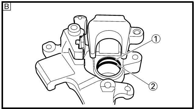
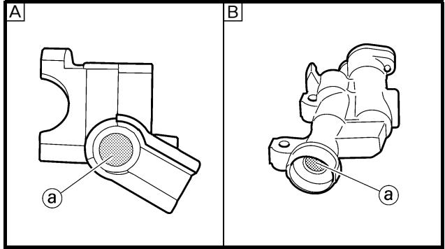
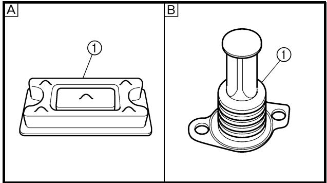
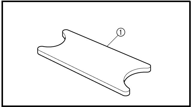
natural_image
Isometric line drawing of a 3D object with a curved top surface and labeled point (1), no text or symbols present.
EC533402
Piston seal kit
-
Remove:
-
Dust seal ①
- Piston seal ②
NOTE:
Remove the piston seals and dust seals by pushing them with a finger.
CAUTION:
Never attempt to pry out piston seals and dust seals.
WARNING
Replace the piston seals and dust seals whenever a caliper is disassembled.
A Front
B Rear
EC5A4000
INSPECTION
EC534112
Master cylinder
- Inspect:
- Master cylinder inner surface @
Wear/scratches → Replace master cylinder assembly.
Stains → Clean.
WARNING
Use only new brake fluid.
A Front
B Rear
- Inspect:
- Diaphragm ①
Crack/damage → Replace.
A Front
B Rear
- Inspect: (front brake only)
- Reservoir float ①
Damage → Replace.
Kit joint de piston
-
Déposer:
-
Joint antipoussière ①
- Joint de piston ②
N.B.:
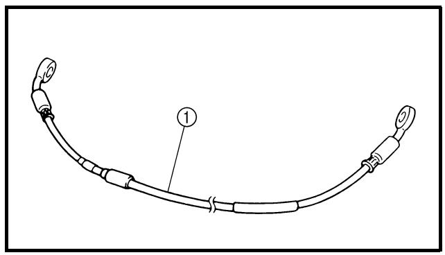
natural_image
Diagram of a curved cable or connector with labeled component 1 (no text or symbols beyond label)
4. Inspect:
- Master cylinder piston ①
- Master cylinder cup ②
Wear/damage/score marks → Replace master cylinder kit.
A Front
B Rear
EC534214
Caliper
1. Inspect:
- Caliper cylinder inner surface ⓐ
Wear/score marks → Replace caliper assembly.
A Front
B Rear
2. Inspect:
- Caliper piston ①
Wear/score marks → Replace caliper piston assembly.
WARNING
Replace the piston seals and dust seals ② whenever a caliper is disassembled.
EC534301
Brake hose
1. Inspect:
- Brake hose ①
Crack/damage → Replace.
EC5A5000
ASSEMBLY AND INSTALLATION
WARNING
- All internal parts should be cleaned in new brake fluid only.
- Internal parts should be lubricated with brake fluid when installed.
- Replace the piston seals and dust seals whenever a caliper is disassembled.
FREIN AVANT ET FREIN ARRIERE VORDER- UND HINTERRADBREMSEN FRENO DELANTERO Y FRENO TRASERO
CHAS

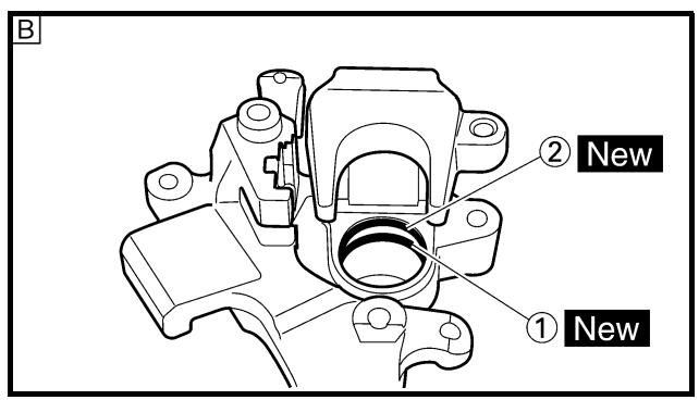
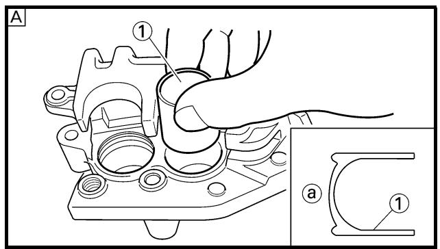
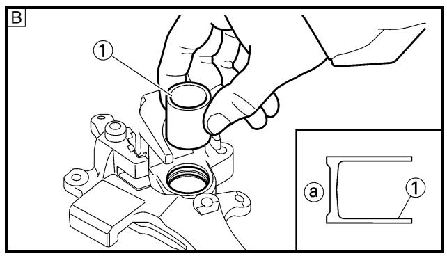
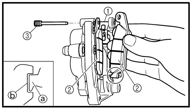
EC5A5800
Caliper piston
-
Clean:
-
Caliper
- Piston seal
- Dust seal
- Caliper piston
Clean them with brake fluid.
-
Install:
-
Piston seal ① New
- Dust seal ② New
WARNING
Always use new piston seals and dust seals.
NOTE:
Fit the piston seals and dust seals onto the slot on caliper correctly.
A Front
B Rear
- Install:
- Caliper piston ①
NOTE:
Apply the brake fluid on the piston wall.
CAUTION:
- Install the piston with its shallow depressed side ⓐ facing the caliper.
- Never force to insert.
A Front
B Rear
Front caliper
-
Install:
-
Pad support ①
- Brake pad ②
- Pad pin ③
NOTE:
- Install the brake pads with their projections
① into the caliper recesses ②.
- Temporarily tighten the pad pin at this point.
2. Install:
- Caliper ①
- Bolt (caliper) ②
23 Nm (2.3 m · kg, 17 ft · lb)
3. Tighten:
- Pad pin ③
18 Nm (1.8 m · kg, 13 ft · lb)
4. Install:
- Pad pin plug ④
3 Nm (0.3 m · kg, 2.2 ft · lb)
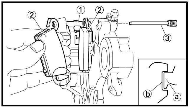
EC5A5100
Rear caliper
1. Install:
- Pad support ①
- Brake pad ②
- Pad pin ③
NOTE:
- Install the brake pads with their projections
① into the caliper recesses ⑥.
- Temporarily tighten the pad pin at this point.
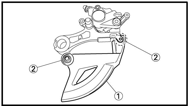
2. Install:
- Disc cover ①
- Bolt (disc cover) ②
10 Nm (1.0 m · kg, 7.2 ft · lb)
FREIN AVANT ET FREIN ARRIERE VORDER- UND HINTERRADBREMSEN FRENO DELANTERO Y FRENO TRASERO

3. Install:
Refer to “FRONT WHEEL AND REAR WHEEL” section.
4. Tighten:
- Pad pin ③
18 Nm (1.8 m · kg, 13 ft · lb)
5. Install:
- Pad pin plug ④
3 Nm (0.3 m · kg, 2.2 ft · lb)
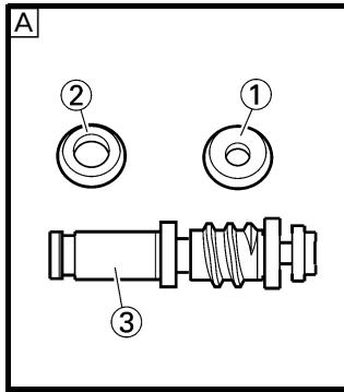
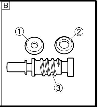
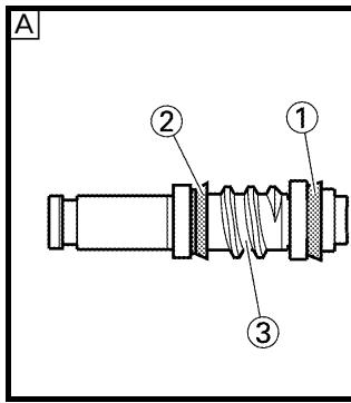
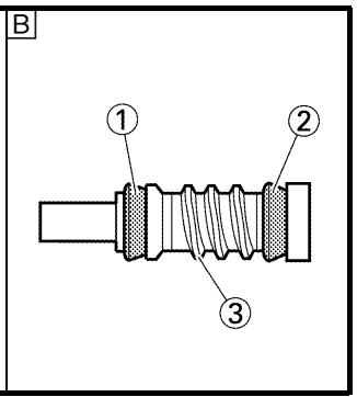
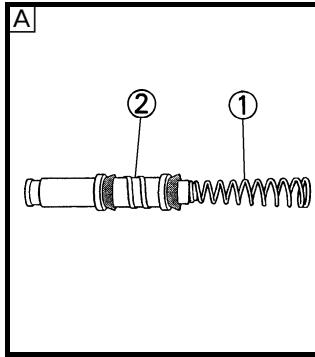
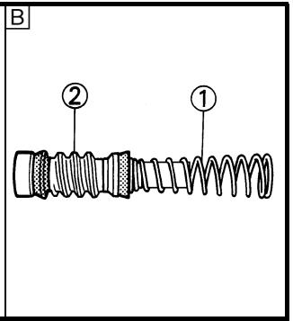
Master cylinder kit
1. Clean:
- Master cylinder
• Master cylinder kit
Clean them with brake fluid.
2. Install:
- Master cylinder cup (primary) ①
- Master cylinder cup (secondary) ②
To master cylinder piston ③.
NOTE:
Apply the brake fluid on the master cylinder cup.
WARNING
After installing, cylinder cup should be installed as shown direction. Wrong installation cause improper brake performance.
A Front
B Rear
3. Install:
- Spring ①
To master cylinder piston ②.
NOTE:
Install the spring at the smaller dia. side.
A Front
B Rear
FREIN AVANT ET FREIN ARRIERE VORDER- UND HINTERRADBREMSEN FRENO DELANTERO Y FRENO TRASERO
CHAS

- Monter:
- Etrier ①
- Roue arrière ②
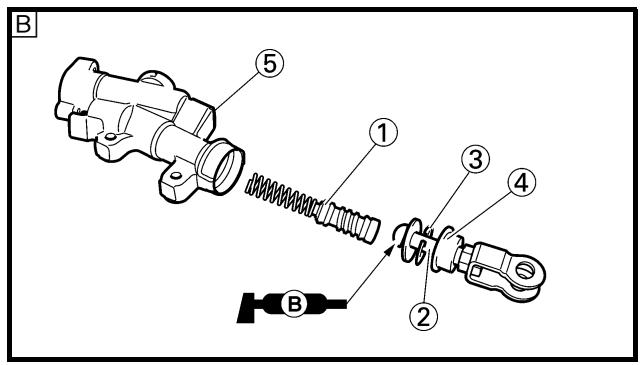
4. Install:
[Front]
- Master cylinder kit ①
- Plain washer ②
- Circlip ③
- Master cylinder boot ④
To master cylinder ⑤.
[Rear]
- Master cylinder kit ①
- Push rod ②
- Circlip ③
- Master cylinder boot ④
To master cylinder ⑤.
NOTE:
- Apply the brake fluid on the master cylinder kit.
- Apply the lithium soap base grease on the tip of the push rod.
- When installing the circlip, use a long nose circlip pliers.
A Front
B Rear
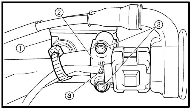
EC5A5310
Front master cylinder
1. Install:
- Master cylinder ①
• Master cylinder bracket ②
- Bolt (master cylinder bracket) ③
9 Nm (0.9 m · kg, 6.5 ft · lb)
NOTE:
- Install the bracket so that the arrow mark ⓐ face upward.
- First tighten the bolts on the upper side of the master cylinder bracket, and then tighten the bolts on the lower side.
FREIN AVANT ET FREIN ARRIERE VORDER- UND HINTERRADBREMSEN FRENO DELANTERO Y FRENO TRASERO
CHAS

4. Monter:
[Avant]
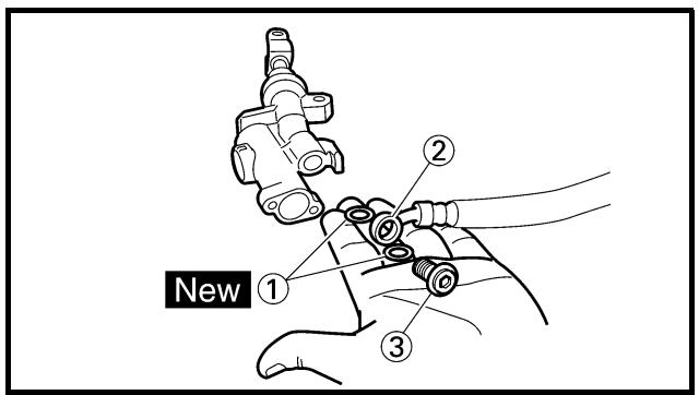
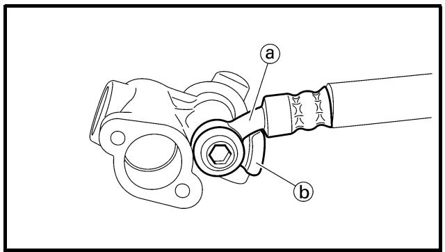
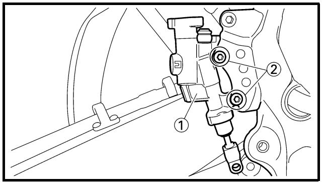
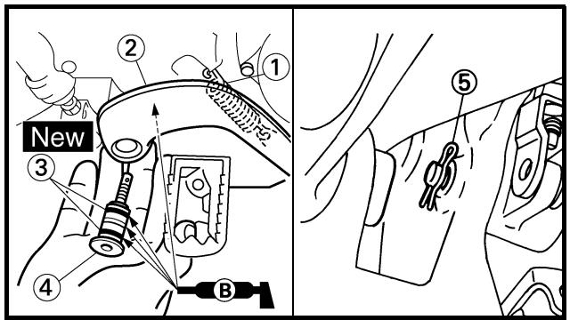
2. Install:
- Brake lever ①
- Bolt (brake lever) ②
6 Nm (0.6 m · kg, 4.3 ft · lb)
- Nut (brake lever) ③
6 Nm (0.6 m · kg, 4.3 ft · lb)
NOTE:
Apply the lithium soap base grease on the brake lever sliding surface, bolt and contacting surface of the master cylinder piston.
Rear master cylinder
1. Install:
- Copper washer ① New
- Brake hose ②
- Union bolt ③
30 Nm (3.0 m · kg, 22 ft · lb)
WARNING
Always use new copper washers.
CAUTION:
Install the brake hose so that its pipe portion ⓐ directs as shown and lightly touches the projection ⓑ on the master cylinder.
2. Install:
- Master cylinder ①
- Bolt (master cylinder) ②
10 Nm (1.0 m · kg, 7.2 ft · lb)
3. Install:
- Spring ①
- Brake pedal ②
- O-ring ③ New
- Bolt (brake pedal) ④
26 Nm (2.6 m · kg, 19 ft · lb)
- Clip ⑤
NOTE:
Apply the lithium soap base grease on the bolt, O-ring and brake pedal bracket.
FREIN AVANT ET FREIN ARRIERE VORDER- UND HINTERRADBREMSEN FRENO DELANTERO Y FRENO TRASERO
CHAS

2. Monter:
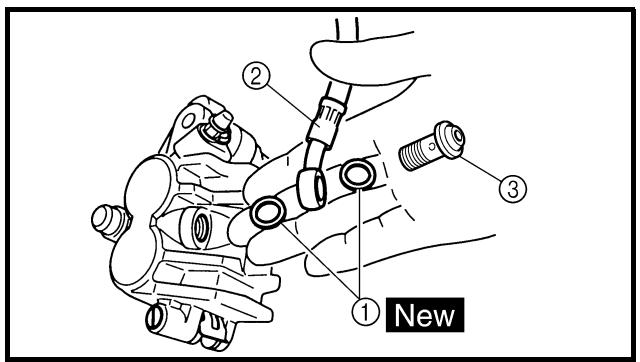
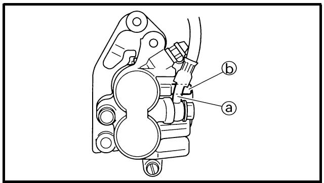
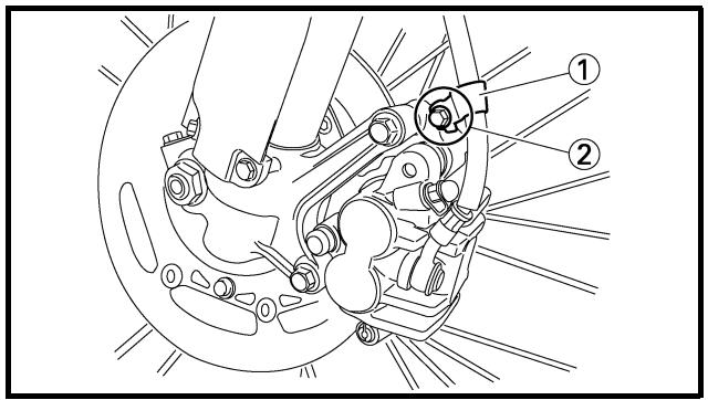
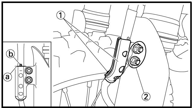
4. Install:
- Pin ①
- Plain washer ②
- Cotter pin ③ New
NOTE:
After installing, check the brake pedal height. Refer to “REAR BRAKE ADJUSTMENT” section in the CHAPTER 3.
Front brake hose
1. Install:
- Copper washer ①
New
- Brake hose ②
- Union bolt ③
30 Nm (3.0 m · kg, 22 ft · lb)

WARNING
Always use new copper washers.
CAUTION:
Install the brake hose so that its pipe portion a directs as shown and lightly touches the projection b on the caliper.
2. Install:
- Brake hose holder ①
- Bolt (brake hose holder) ②
10 Nm (1.0 m · kg, 7.2 ft · lb)
3. Install:
- Brake hose holder ①
- Nut (brake hose holder) ②
7 Nm (0.7 m · kg, 5.1 ft · lb)
NOTE:
Align the top ⓐ of the brake hose holder with the paint ⓑ of the brake hose.
FREIN AVANT ET FREIN ARRIERE VORDER- UND HINTERRADBREMSEN FRENO DELANTERO Y FRENO TRASERO

4. Monter:
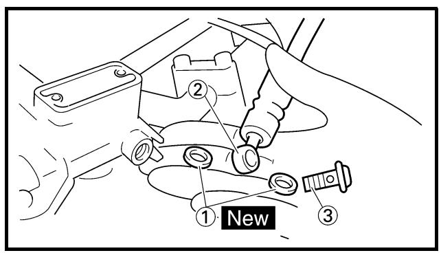
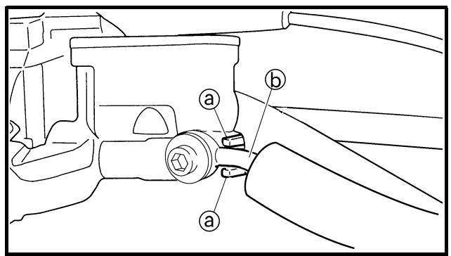
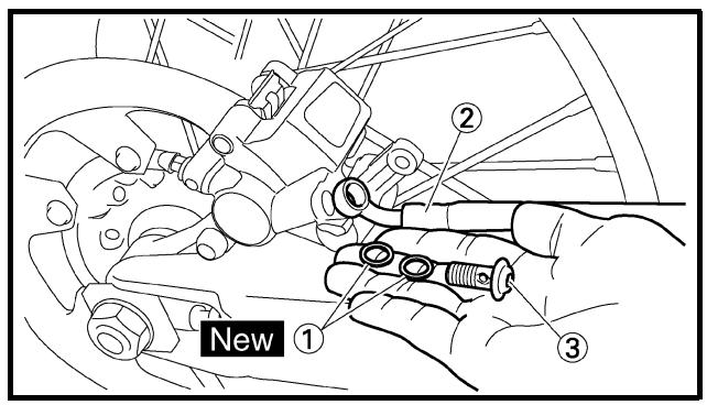
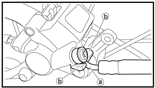
-
Pass the brake hose through the hose guides ①.
-
Install:
-
Copper washer ① New
- Brake hose ②
- Union bolt ③
30 Nm (3.0 m · kg, 22 ft · lb)
WARNING
Always use new copper washers.
CAUTION:
Install the brake hose so that it contacts the master cylinder projection ① and that its bent portion ② faces downward.
Rear brake hose
-
Install:
-
Copper washer ① New
- Brake hose ②
- Union bolt ③
30 Nm (3.0 m · kg, 22 ft · lb)
WARNING
Always use new copper washers.
CAUTION:
Install the brake hose so that its pipe portion a directs as shown and lightly touches the projection b on the caliper.
FREIN AVANT ET FREIN ARRIERE VORDER- UND HINTERRADBREMSEN FRENO DELANTERO Y FRENO TRASERO

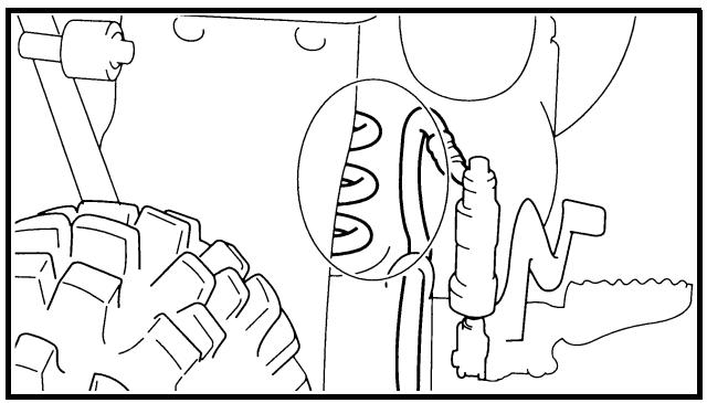
natural_image
Line drawing of a vehicle's wheel and gear assembly, showing gear and wheel components (no text or symbols)
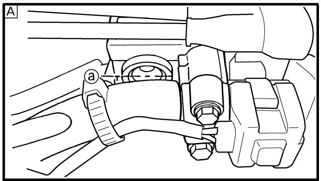
natural_image
Technical line drawing of a mechanical assembly with labeled parts (a and b), no readable text or symbols present.
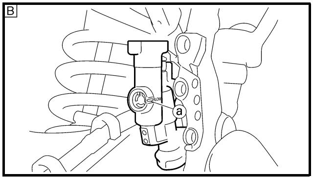
2. Install:
- Brake hose holder ①
- Screw (brake hose holder) ②
2 Nm (0.2 m · kg, 1.4 ft · lb)
CAUTION:
After installing the brake hose holders, make sure the brake hose does not contact the spring (rear shock absorber). If it does, correct its twist.
Brake fluid
1. Fill:
- Brake fluid
Until the fluid level reaches “LOWER” level line ⓐ.

Recommended brake fluid: DOT #4
WARNING
- Use only the designated quality brake fluid:
otherwise, the rubber seals may deteriorate, causing leakage and poor brake performance.
- Refill with the same type of brake fluid; mixing fluids may result in a harmful chemical reaction and lead to poor performance.
- Be careful that water does not enter the master cylinder when refilling. Water will significantly lower the boiling point of the fluid and may result in vapor lock.
CAUTION:
Brake fluid may erode painted surfaces or plastic parts. Always clean up spilled fluid immediately.
A Front
B Rear
FREIN AVANT ET FREIN ARRIERE VORDER- UND HINTERRADBREMSEN FRENO DELANTERO Y FRENO TRASERO
CHAS

2. Monter:
Fluid at lower level → Fill up.
Refer to "BRAKE FLUID LEVEL INSPECTION" section in the CHAPTER 3.
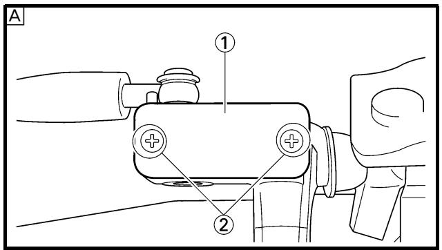
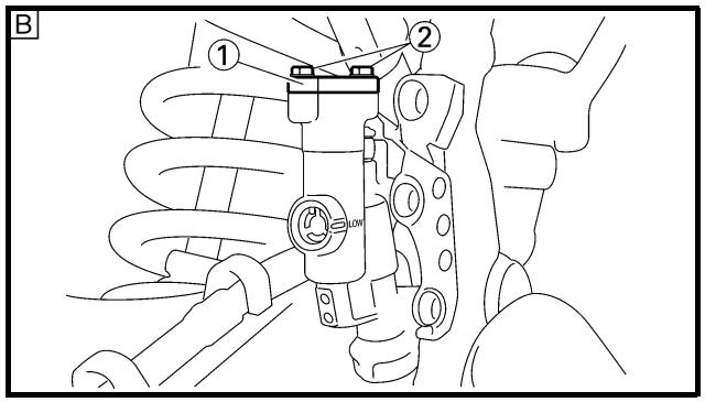
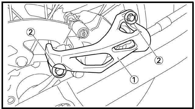
4. Install:
[Front]
- Reservoir float
- Diaphragm
- Master cylinder cap ①
- Screw (master cylinder cap) ②
2 Nm (0.2 m · kg, 1.4 ft · lb)
[Rear]
- Diaphragm
- Master cylinder cap ①
- Bolt (master cylinder cap) ②
2 Nm (0.2 m · kg, 1.4 ft · lb)
CAUTION:
After installation, while pulling the lever in or pushing down on the pedal, check whether there is any brake fluid leaking where the union bolts are installed respectively at the master cylinder and caliper.
A Front
B Rear
-
Install: (rear brake only)
-
Protector ①
- Bolt (protector) ②
7 Nm (0.7 m · kg, 5.1 ft · lb)
FREIN AVANT ET FREIN ARRIERE VORDER- UND HINTERRADBREMSEN FRENO DELANTERO Y FRENO TRASERO
2. Purger l'air:
- Protection ①
- Boulon (protection) ②
7 Nm (0,7 m · kg, 5,1 ft · lb)
4. Montieren:
[Vorn]
Extent of removal:
① Front fork removal
| Extent of removal | Order | Part name | Q'ty | Remarks |
| Preparation for removal | | FRONT FORK REMOVALHold the machine by placing the suitable stand under the engine.Front wheelFront caliperHeadlightHandlebar | | WARNINGSupport the machine securely so there is no danger of it falling over.Refer to “FRONT WHEEL AND REAR WHEEL” section.Refer to “FRONT BRAKE AND REAR BRAKE” section.Refer to “HANDLEBAR” section. |
| 1 | 1 | Protector | 1 | |
| 2 | Pinch bolt (handle crown) | 2 | Only loosening. |
| 3 | Cap bolt | 1 | Loosen when disassembling the front fork. |
| 4 | Pinch bolt (under bracket) | 2 | Only loosening. |
| 5 | Front fork | 1 | |
FOURCHE
Extent of removal:
① Oil seal removal
② Damper rod removal
| Extent of removal | Order | Part name | Q'ty | Remarks |
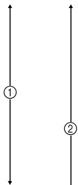 ↓ ↓ | 12345678910111213 | FRONT FORK DISASSEMBLYCap boltFork springDust sealStopper ringInner tubeOuter tubePiston metalSlide metalOil seal washerOil sealSpring guideBase valveDamper rod | 1111111111111111111111111111111111111111111111111111111111111111111111111111111111111111111111111111 | Refer to “REMOVAL POINTS”.Drain the fork oil.Refer to “REMOVAL POINTS”.Use special tool.Refer to “REMOVAL POINTS”. |
DEMONTAGE DE LA FOURCHE
The front fork requires careful attention. So it is recommended that the front fork be maintained at the dealers.
CAUTION:
To prevent an accidental explosion of air, the following instructions should be observed:
- The front fork with a built-in piston rod has a very sophisticated internal construction and is particularly sensitive to foreign material.
Use enough care not to allow any foreign material to come in when the oil is replaced or when the front fork is disassembled and reassembled.
- Before removing the cap bolts or front forks, be sure to extract the air from the air chamber completely.
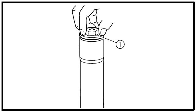

EC553000
REMOVAL POINTS
EC553150
Cap bolt
- Remove:
- Cap bolt ①
From the outer tube.
NOTE:
Before removing the front fork from the machine, loosen the cap bolt.
- Remove:
- Cap bolt ①
NOTE:
Hold the locknut ② and remove the cap bolt.
REMARQUES CONCERNANT LA MANIPULATION
N.B.:
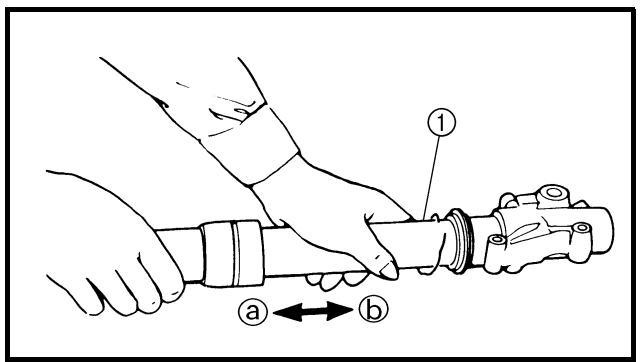
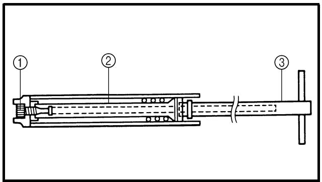
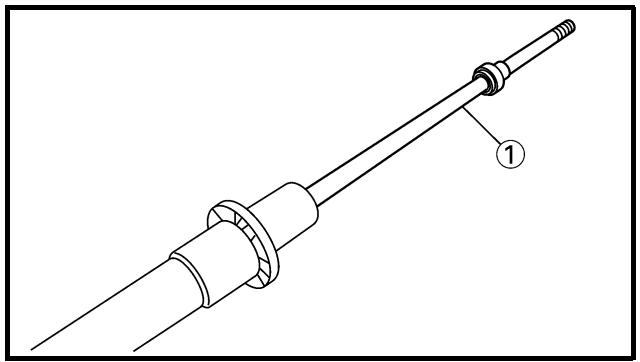
natural_image
Technical line drawing of a mechanical component with labeled part 1 (no text or symbols beyond label)
EC553201
Inner tube
1. Remove:
- Dust seal ①
- Stopper ring ②
Using slotted-head screwdriver.
CAUTION:
Take care not to scratch the inner tube.
2. Remove:
- Inner tube ①
Oil seal removal steps:
- Push in slowly ⓐ the inner tube just before it bottoms out and then pull it back quickly ⓑ.
- Repeat this step until the inner tube can be pulled out from the outer tube.
EC553311
Damper rod
1. Remove:
- Base valve ①
- Damper rod ②
NOTE:
Use a damper rod holder ③ to lock the damper rod.
Damper rod holder: YM-01494/90890-01494
EC554000
INSPECTION
EC554100
Damper rod
1. Inspect:
- Damper rod ①
Bend/damage → Replace damper rod.
CAUTION:
The front fork with a built-in piston rod has a very sophisticated internal construction and is particularly sensitive to foreign material.
Use enough care not to allow any foreign material to come in when the oil is replaced or when the front fork is disassembled and reassembled.
Tube plongeur
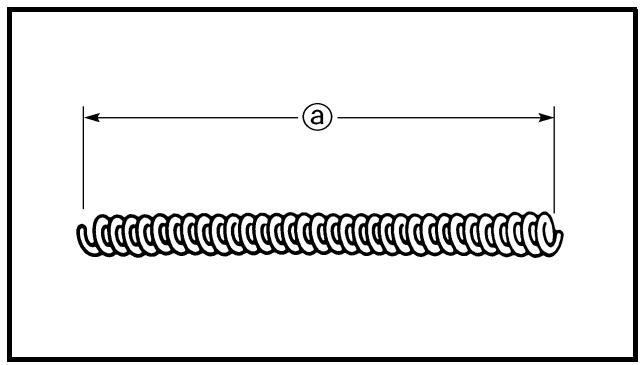
natural_image
Diagram of a coiled spring with labeled dimension 'a' (no text or symbols beyond label)
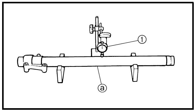
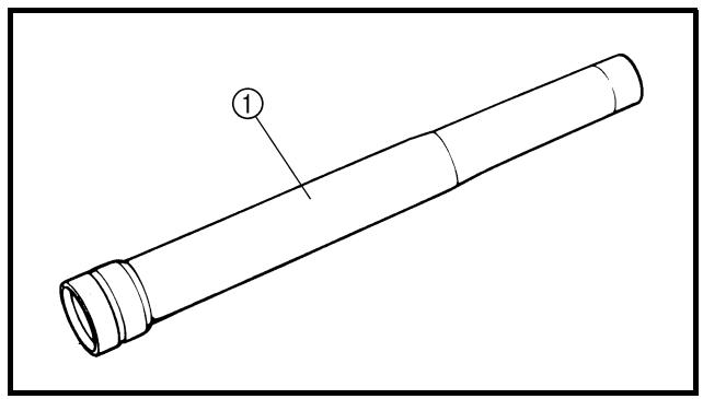
natural_image
Technical line drawing of a cylindrical pipe fitting with labeled component (1), no text or symbols present
EC554200
Base valve
1. Inspect:
- Valve assembly ①
Wear/damage → Replace.
- O-ring ②
Damage → Replace.
EC554400
Fork spring
1. Measure:
- Fork spring free length ⓐ
Out of specification → Replace.
| Fork spring free length: |
| Standard | Limit |
| 460 mm (18.1 in) | 455 mm (17.9 in) |
EC554502
Inner tube
1. Inspect:
- Inner tube surface @
Score marks → Repair or replace.
Use #1,000 grit wet sandpaper.
Damaged oil lock piece → Replace.
- Inner tube bends
Out of specification → Replace.
Use the dial gauge ①.
| Inner tube bending limit:0.2 mm (0.008 in) |
NOTE:
The bending value is shown by one half of the dial gauge reading.

WARNING
Do not attempt to straighten a bent inner tube as this may dangerously weaken the tube.
EC554600
Outer tube
1. Inspect:
- Outer tube ①
Score marks/wear/damage → Replace.
Soupape de base
-
Contrôler:
-
Soupape complète ①
Usure/endommagement → Rem-
placer.
- Joint torique ②
Endommagement → Remplacer.
Gabelventil
EC554700
Cap bolt
1. Inspect:
- Cap bolt ①
- O-ring ②
- Air bleed screw ③
Wear/damage → Replace.
EC555000
ASSEMBLY AND INSTALLATION
Front fork assembly
- Wash the all parts in a clean solvent.
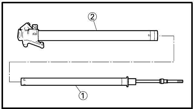
2. Install:
- Damper rod ①
To inner tube ②.
CAUTION:
To install the damper rod into the inner tube, hold the inner tube aslant. If the inner tube is held vertically, the damper rod may fall into it, damaging the valve inside.
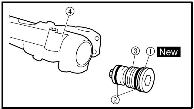
3. Install:
New
- Copper washer ①
- O-ring ②
- Base valve ③
To inner tube ④.
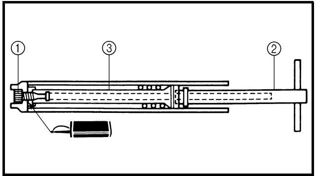
4. Tighten:
- Base valve ①

55 Nm (5.5 m · kg, 40 ft · lb)
NOTE:
- Use a damper rod holder ② to lock the damper rod ③.
- Apply the LOCTITE® on the base valve thread.
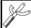
Damper rod holder: YM-01494/90890-01494
Boulon capuchon
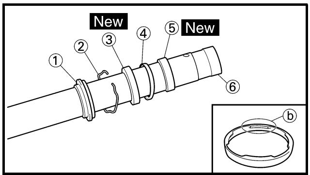
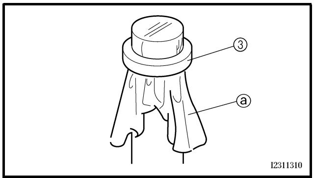
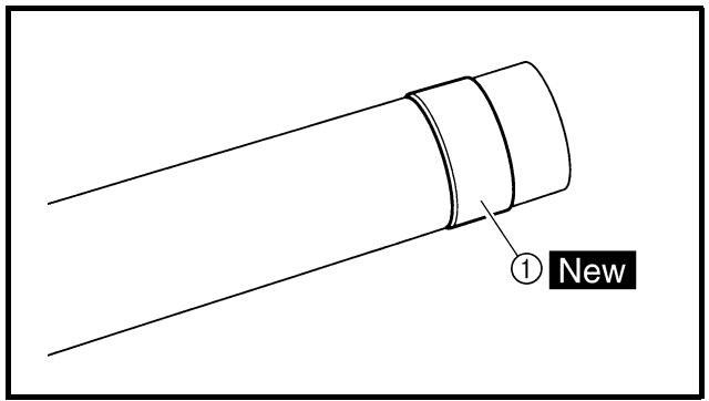
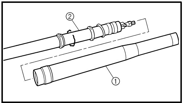
5. Install:
To damper rod ③.
NOTE:
- Install the spring guide with its smaller dia. end @ facing downward.
- With its thread ⑥ facing upward, fully finger tighten the locknut onto the damper rod.
6. Install:
- Dust seal ①
- Stopper ring ②
- Oil seal ③ New
- Oil seal washer ④
- Slide metal ⑤ New
To inner tube ⑥.
NOTE:
- Apply the fork oil on the inner tube.
- When installing the oil seal, use vinyl seat ⓐ with fork oil applied to protect the oil seal lip.
- Install the oil seal with its manufacture's marks or number facing the axle holder side.
- Install the oil seal washer with its projections
⑥ facing upward.
7. Install:
- Piston metal ① New
NOTE:
Install the piston metal onto the slot on inner tube.
8. Install:
- Outer tube ①
To inner tube ②.
5. Monter:
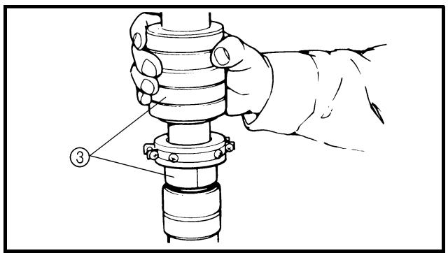
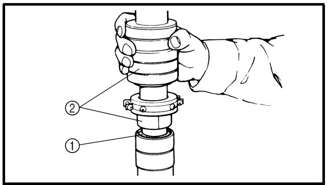
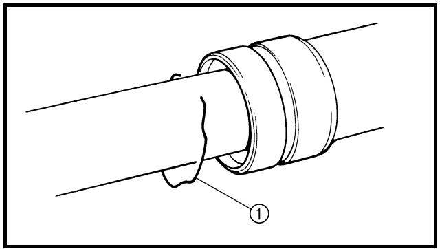
natural_image
Technical line drawing of a mechanical joint or pipe connection (no text or symbols)

9. Install:
- Slide metal ①
- Oil seal washer ②
To outer tube slot.
NOTE:
Press the slide metal into the outer tube with fork seal driver ③.
Fork seal driver:
YM-A0948/90890-01502
10. Install:
- Oil seal ①
NOTE:
Press the oil seal into the outer tube with fork seal driver ②.
Fork seal driver:
YM-A0948/90890-01502
11. Install:
- Stopper ring ①
NOTE:
Fit the stopper ring correctly in the groove in the outer tube.
12. Install:
- Dust seal ①
NOTE:
Apply the lithium soap base grease on the inner tube.
9. Monter:
natural_image
Illustration of a hand holding a mechanical component with directional arrows indicating movement (no text or symbols)
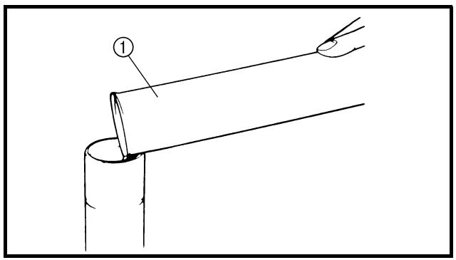
13. Check:
- Inner tube smooth movement
Tightness/binding/rough spots → Repeat the steps 2 to 12.
14. Compress the front fork fully.
15. Fill:
- Front fork oil
Until outer tube top surface with recommended fork oil ①.

Recommended oil: Suspension oil "S1"
CAUTION:
- Be sure to use recommended fork oil. If other oils are used, they may have an excessively adverse effect on the front fork performance.
- Never allow foreign materials to enter the front fork.
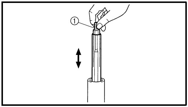
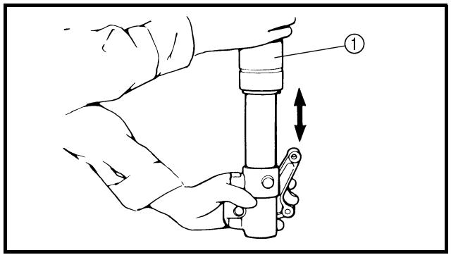
- After filling, pump the damper rod ① slowly up and down more than 10 times to distribute the fork oil.
17. Fill:
- Front fork oil
Until outer tube top surface with recommended fork oil once more.
- After filling, pump the outer tube ① slowly up and down (about 200 mm (7.9 in) stroke) to distribute the fork oil once more.
NOTE:
Be careful not to excessive full stroke. A stroke of 200 mm (7.9 in) or more will cause air to enter. In this case, repeat the steps 15 to 18.
13. Contrôler:
- Wait ten minutes until the air bubbles have been removed from the front fork, and the oil has dispense evenly in system before setting recommended oil level.
NOTE:
Fill with the fork oil up to the top end of the outer tube, or the fork oil will not spread over to every part of the front forks, thus making it impossible to obtain the correct level.
Be sure to fill with the fork oil up to the top of the outer tube and bleed the front forks.
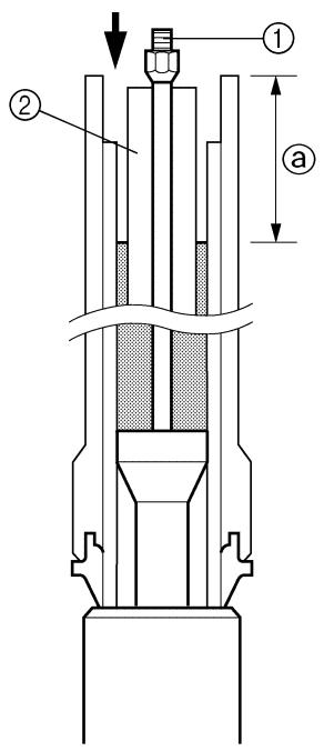
311404
20. Measure:
- Oil level (left and right) ⓐ
Out of specification → Adjust.

Standard oil level:
132 mm (5.20 in)
* 125 mm (4.92 in)
Extent of adjustment:
95 \~ 150 mm (3.74 \~ 5.91 in)
From top of outer tube with inner tube and damper rod ① fully compressed without spring.
* Except for USA and CDN
NOTE:
Be sure to install the spring guide ② when checking the oil level.

WARNING
Never fail to make the oil level adjustment between the maximum and minimum level and always adjust each front fork to the same setting. Uneven adjustment can cause poor handling and loss of stability.
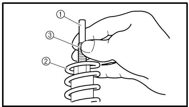
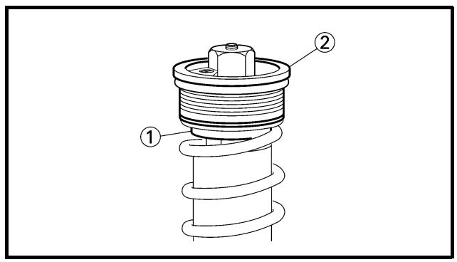
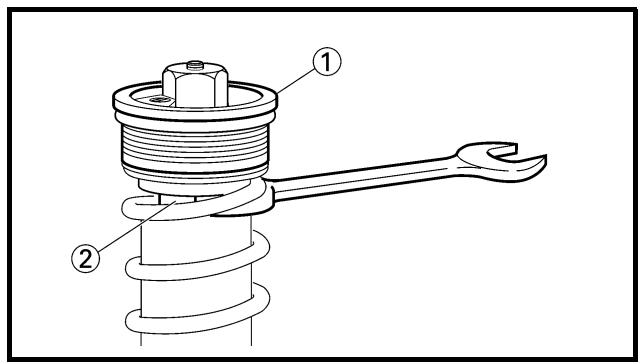
21. Measure:
- Distance ⓐ
Out of specification → Turn into the locknut.

Distance ⓐ:
18 mm (0.71 in) or more
Between damper rod ① top and locknut ② top.
22. Loosen:
- Rebound damping adjuster ①
NOTE:
- Loosen the rebound damping adjuster finger tight.
- Record the set position of the adjuster (the amount of turning out the fully turned in position).
23. Install:
NOTE:
- Install the fork spring with the damper rod ③ pulled up.
- After installing the fork spring, hold the damper rod end so that it will not go down.
24. Install:
NOTE:
Fully finger tighten the cap bolt onto the damper rod.
25. Tighten:
- Cap bolt (locknut) ①
29 Nm (2.9 m · kg, 21 ft · lb)
NOTE:
Hold the locknut ② and tighten the cap bolt with specified torque.
21. Mesurer:
- Distance ⓐ
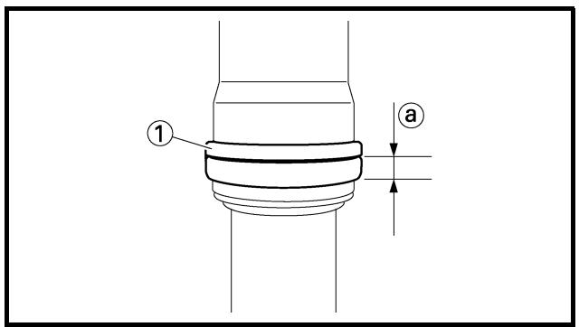
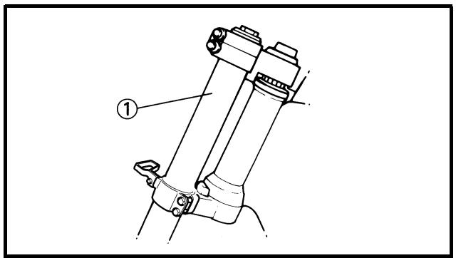
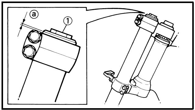
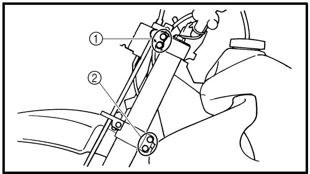
26. Install:
- Cap bolt ①
To outer tube.
NOTE:
Temporarily tighten the cap bolt.
27. Install:
- Protector guide ①
NOTE:
Install the protector guide with its wider side ⓐ facing downward.
Installation
1. Install:
- Front fork ①
NOTE:
- Temporarily tighten the pinch bolts (under bracket).
- Do not tighten the pinch bolts (handle crown) yet.
2. Tighten:
- Cap bolt ①
30 Nm (3.0 m · kg, 22 ft · lb)
3. Adjust:
- Front fork top end ⓐ

Front fork top end (standard) ⓐ: Zero mm (zero in)
4. Tighten:
- Pinch bolt (handle crown) ①
- Pinch bolt (under bracket) ②
Tighten the under bracket to specified torque. If torqued too much, it may cause the front fork to malfunction.
- Monter:
5. Install:
- Speed sensor lead ①
- Plate 1 ②
- Bolt (plate 1) ③
4 Nm (0.4 m · kg, 2.9 ft · lb)
To protector (right) ④.
NOTE:
Install the speed sensor lead so that its paint ① directs as shown and align the bottom ② of the plate 1 with the same paint.
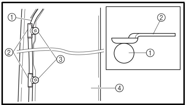
6. Install:
- Speed sensor lead ①
- Plate 2 ②
- Screw (plate 2) ③
0.5 Nm (0.05 m · kg, 0.36 ft · lb)
To protector (right) ④.
NOTE:
Install the plate 2 in the direction as shown.
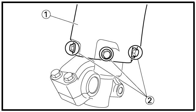
7. Install:
- Protector ①
- Bolt (protector) ②
7 Nm (0.7 m · kg, 5.1 ft · lb)
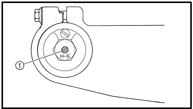
8. Adjust:
- Rebound damping force
NOTE:
Turn in the damping adjuster ① finger-tight and then turn out to the originally set position.
5. Monter:
- Protection ①
- Boulon (protection) ②
7 Nm (0,7 m · kg, 5,1 ft · lb)
7. Montieren:
Extent of removal:
① Handlebar removal
| Extent of removal | Order | Part name | Q'ty | Remarks |
| Preparation for removal | | HANDLEBAR REMOVALHeadlight | | |
| 1 | 1 | Hot starter cable | 1 | Disconnect at the lever side. |
| 2 | Hot starter lever holder | 1 | |
| 3 | Clutch cable | 1 | Disconnect at the lever side. |
| 4 | Clutch lever holder | 1 | Disconnect the clutch switch lead. |
| 5 | “ENGINE STOP” button | 1 | Disconnect the “ENGINE STOP” button lead. |
| 6 | Master cylinder | 1 | Refer to “REMOVAL POINTS”. |
| 7 | Start switch | 1 | Disconnect the start switch lead. |
| 8 | Throttle cable cap | 1 | |
| 9 | Throttle cable #1 (pulled) | 1 | Disconnect at the throttle side. |
| 10 | Throttle cable #2 (pushed) | 1 | Disconnect at the throttle side. |
| 11 | Grip (right) | 1 | Refer to “REMOVAL POINTS”. |
| 12 | Tube guide | 1 | |
| 13 | Grip (left) | 1 | Refer to “REMOVAL POINTS”. |
| 14 | Handlebar holder (upper) | 2 | |
| 15 | Handlebar | 1 | |
| 16 | Handlebar holder (lower) | 2 | |
GUIDON
EC5B3000
REMOVAL POINTS
EC5B3100
Master cylinder
- Remove:
• Master cylinder bracket ①
- Master cylinder ②
CAUTION:
- Do not let the master cylinder hang on the brake hose.
- Keep the master cylinder cap side horizontal to prevent air from coming in.
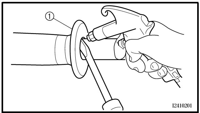
natural_image
Illustration of a hand using a tool to adjust or install a mechanical component, no text or symbols present
EC5B3200
Grip
- Remove:
- Grip ①
NOTE:
Blow in air between the handlebar or tube guide and the grip. Then remove the grip which has become loose.
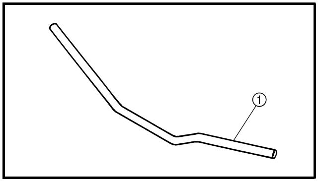
natural_image
Simple line drawing of a bent pipe or tube with a labeled point (1) on the end, no text or symbols present.
EC5B4000
INSPECTION
EC5B4100
Handlebar
- Inspect:
- Handlebar ①
Bends/cracks/damage → Replace.
WARNING
Do not attempt to straighten a bent handlebar as this may dangerously weaken the handlebar.
POINTS DE DEPOSE
Maître-cylindre
- Déposer:

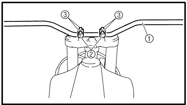
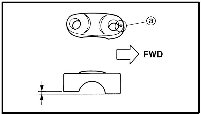
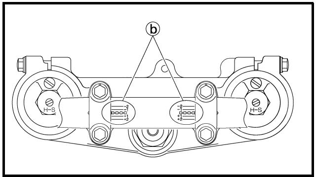
EC5B5000
ASSEMBLY AND INSTALLATION
Handlebar
1. Install:
- Handlebar holder (lower) ①
- Plain washer ②
- Nut [handlebar holder (lower)] ③
NOTE:
- Install the handlebar holder (lower) with its side having the greater distance ⓐ from the mounting bolt center facing forward.
- Apply the lithium soap base grease on the thread of the handlebar holder (lower).
- Installing the handlebar holder (lower) in the reverse direction allows the front-to-rear offset amount of the handlebar position to be changed.
- Do not tighten the nut yet.
2. Install:
- Handlebar ①
- Handlebar holder (upper) ②
- Bolt [handlebar holder (upper)] ③
- The handlebar holder (upper) should be installed with the punched mark @ forward.
- Install the handlebar so that the marks ⑥ are in place on both sides.
- Install the handlebar so that the projection © of the handlebar holder (upper) is positioned at the mark on the handlebar as shown.
- First tighten the bolts on the front side of the handlebar holder (upper), and then tighten the bolts on the rear side.
ASSEMBLAGE ET MONTAGE
Guidon
- Monter:
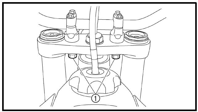
natural_image
Technical line drawing of a mechanical assembly with no visible text or symbols
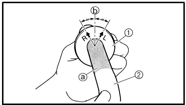
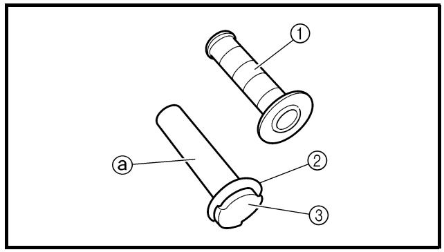
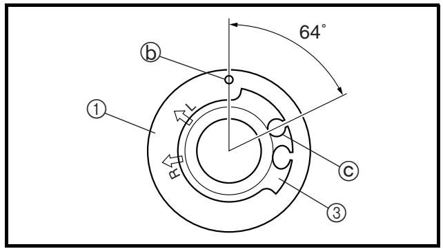
3. Tighten:
- Nut [handlebar holder (lower)] ①
Apply the adhesive to the handlebar ②.
NOTE:
- Before applying the adhesive, wipe off grease or oil on the handlebar surface ⓐ with a lacquer thinner.
- Install the grip (left) to the handlebar so that the line ⑥ between the two arrow marks faces straight upward.
5. Install:
Apply the adhesive on the tube guide ③.
NOTE:
- Before applying the adhesive, wipe off grease or oil on the tube guide surface ⓐ with a lacquer thinner.
- Install the grip to the tube guide so that the grip match mark ⓑ and tube guide slot Ⓒ form the angle as shown.
3. Serrer:
- Lenkergriff links ①
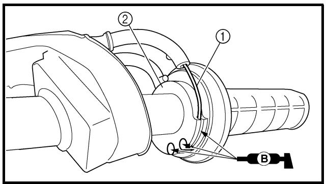
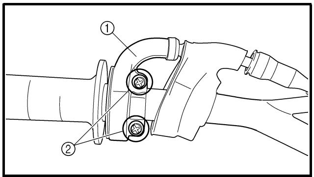
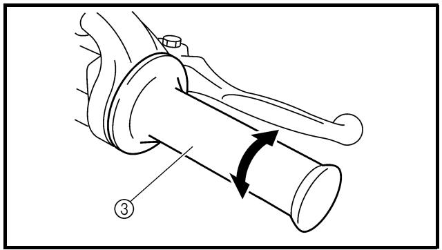
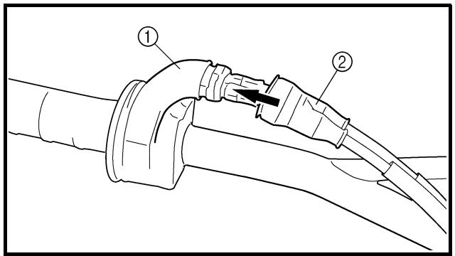
6. Install:
- Cover (grip cap) ①
- Throttle grip ②
NOTE:
Apply the lithium soap base grease on the throttle grip sliding surface.
7. Install:
- Throttle cables ①
To tube guide ②.
NOTE:
Apply the lithium soap base grease on the throttle cable end and tube guide cable winding portion.
8. Install:
- Throttle cable cap ①
- Screw (throttle cable cap) ②
4 Nm (0.4 m · kg, 2.9 ft · lb)

WARNING
After tightening the screws, check that the throttle grip ③ moves smoothly. If it does not, retighten the bolts for adjustment.
9. Install:
- Cover (grip cap) ①
- Cover (throttle cable cap) ②
6. Monter:
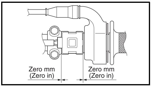
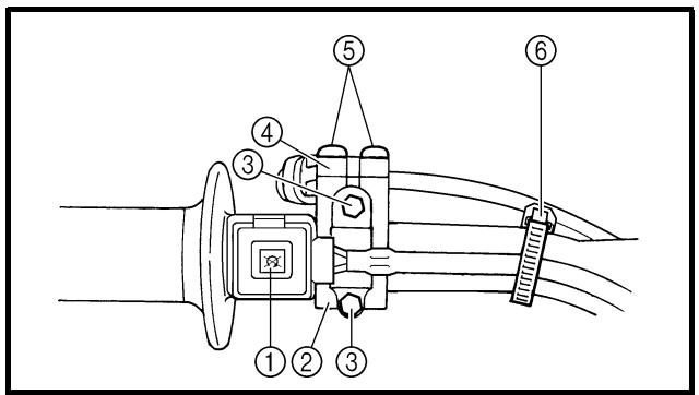
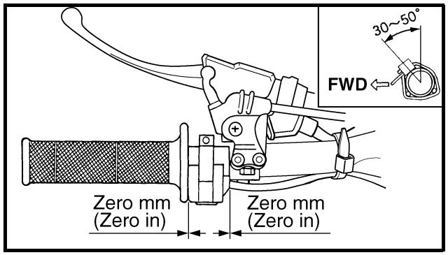
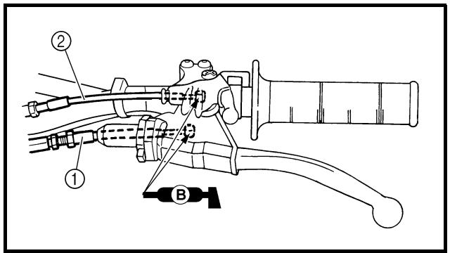
10. Install:
- Start switch ①
- Master cylinder ②
• Master cylinder bracket ③
- Bolt (master cylinder bracket) ④
9 Nm (0.9 m · kg, 6.5 ft · lb)
- Clamp ⑤
NOTE:
- The start switch and master cylinder bracket should be installed according to the dimensions shown.
- Install the bracket so that the arrow mark ⓐ faces upward.
- First tighten the bolt on the upper side of the master cylinder bracket, and then tighten the bolt on the lower side.
11. Install:
- “ENGINE STOP” button ①
- Clutch lever holder ②
- Bolt (clutch lever holder) ③
4 Nm (0.4 m · kg, 2.9 ft · lb)
- Hot starter lever holder ④
- Bolt (hot starter lever holder) ⑤
4 Nm (0.4 m · kg, 2.9 ft · lb)
- Clamp ⑥
NOTE:
- The “ENGINE STOP” button, clutch lever holder and clamp should be installed according to the dimensions shown.
- Pass the “ENGINE STOP” button lead in the middle of the clutch lever holder.
12. Install:
- Clutch cable ①
- Hot starter cable ②
NOTE:
Apply the lithium soap base grease on the clutch cable end and hot starter cable end.
10. Monter:
- Clutch lever free play
Refer to “CLUTCH ADJUSTMENT” section in the CHAPTER 3.
- Hot starter lever free play
Refer to “HOT STARTER LEVER ADJUSTMENT” section in the CHAPTER 3.
13. Régler:
Extent of removal:
① Under bracket removal
② Bearing removal
| Extent of removal | Order | Part name | Q'ty | Remarks |
| Preparation for removal | | STEERING REMOVALHold the machine by placing the suitable stand under the engine.HeadlightHandlebarHose guideFront fender | | WARNINGSupport the machine securely so there is no danger of it falling over.Refer to “HANDLEBAR” section. |
| 12 | 1 | Multi-function meter | 1 | |
| 2 | Multi-function meter bracket | 1 | |
| 3 | Main switch | 1 | Disconnect the main switch lead. |
| 4 | Steering shaft nut | 1 | |
| 5 | Front fork | 2 | Refer to “FRONT FORK” section. |
| 6 | Handle crown | 1 | |
| 7 | Ring nut | 1 | Use special tool.Refer to “REMOVAL POINTS”. |
| 8 | Under bracket | 1 | |
| 9 | Bearing race cover | 1 | |
DIRECTION
EC563000
REMOVAL POINTS
EC563202
Ring nut
- Remove:
- Ring nut ①
Use the ring nut wrench ②.
Ring nut wrench:
YU-33975/90890-01403
WARNING
Support the steering shaft so that it may not fall down.
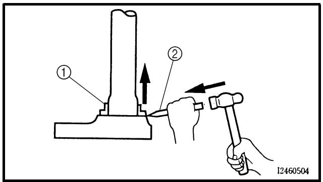
EC563300
Bearing (lower)
- Remove:
- Bearing (lower) ①
Use the floor chisel ②.
CAUTION:
Take care not to damage the steering shaft thread.
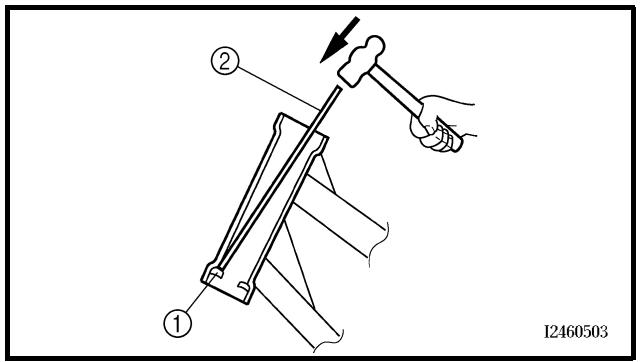
Bearing race
- Remove:
- Bearing race ①
Remove the bearing race using long rod ② and the hammer.
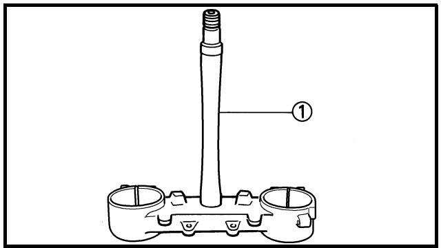
EC564000
INSPECTION
EC564200
Steering shaft
- Inspect:
- Steering shaft ①
Bend/damage → Replace.
POINTS DE DEPOSE
Ecrou de direction
- Déposer:
Hakenschlüssel:
YU-33975/90890-01403
WARNING
natural_image
Illustration of a hand turning a ball bearing with a rotating arrow (no text or symbols)
Bearing and bearing race
- Wash the bearings and bearing races with a solvent.
-
Inspect:
-
Bearing ①
- Bearing race
Pitting/damage → Replace bearings and bearing races as a set.
Install the bearing in the bearing races. Spin the bearings by hand. If the bearings hang up or are not smooth in their operation in the bearing races, replace bearings and bearing races as a set.
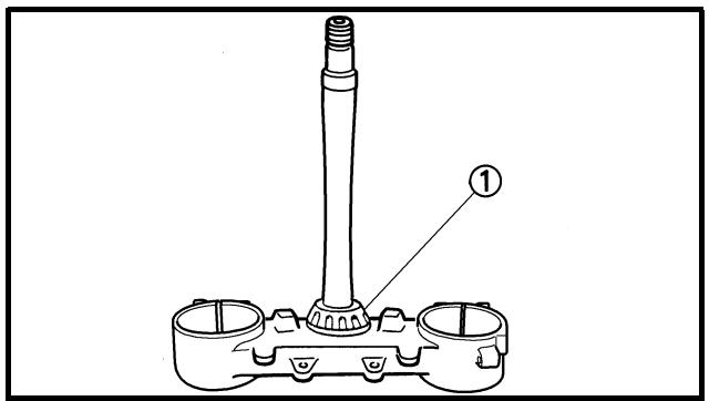
EC565000
ASSEMBLY AND INSTALLATION
Under bracket
- Install:
- Bearing (lower) ①
NOTE:
Apply the lithium soap base grease on the dust seal lip and bearing inner circumference.
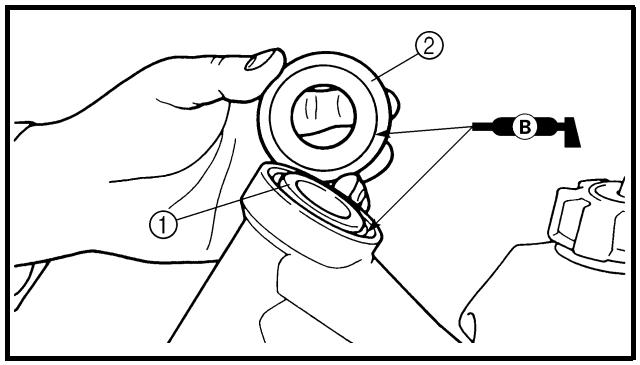
-
Install:
-
Bearing race
- Bearing (upper) ①
- Bearing race cover ②
NOTE:
Apply the lithium soap base grease on the bearing and bearing race cover lip.
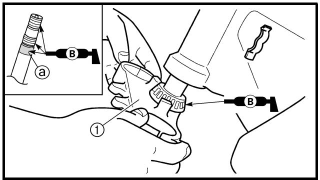
- Install:
- Under bracket ①
NOTE:
Apply the lithium soap base grease on the bearing, the portion ⓐ and thread of the steering shaft.
- Cojinate (inferior) ①
NOTA:
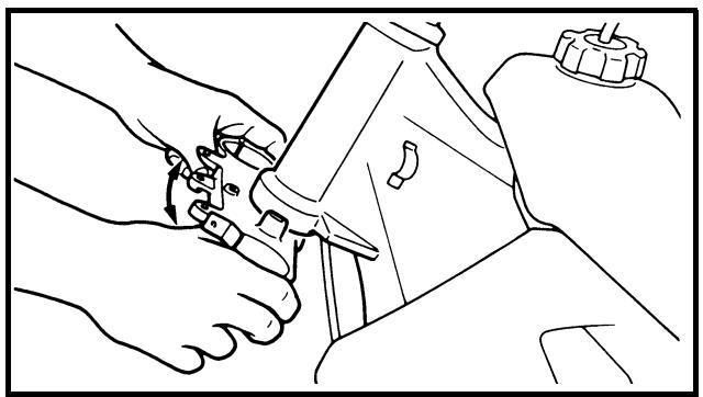
natural_image
Line drawing of hands using a tool to adjust or install a mechanical component (no text or symbols present)

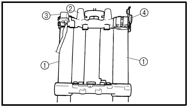
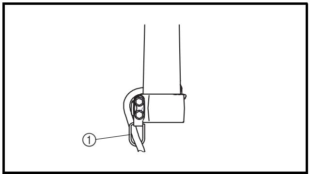
4. Install:
- Ring nut ①
7 Nm (0.7 m · kg, 5.1 ft · lb)
Tighten the ring nut using the ring nut wrench ②.
Refer to "STEERING HEAD INSPECTION AND ADJUSTMENT" section in the CHAPTER 3.
- Check the steering shaft by turning it lock to lock. If there is any binding, remove the steering shaft assembly and inspect the steering bearings.
6. Install:
- Plain washer ①
7. Install:
- Front fork ①
- Handle crown ②
- Main switch ③
- Hose guide bracket ④
NOTE:
- Temporarily tighten the pinch bolts (under bracket).
- Do not tighten the pinch bolts (handle crown) yet.
8. Install:
- Guide (speed sensor lead) ①
NOTE:
After installing the guide as shown, pass the speed sensor lead through the guide.
4. Monter:
- Ecrou de direction ①
7 Nm (0,7 m · kg, 5,1 ft · lb)
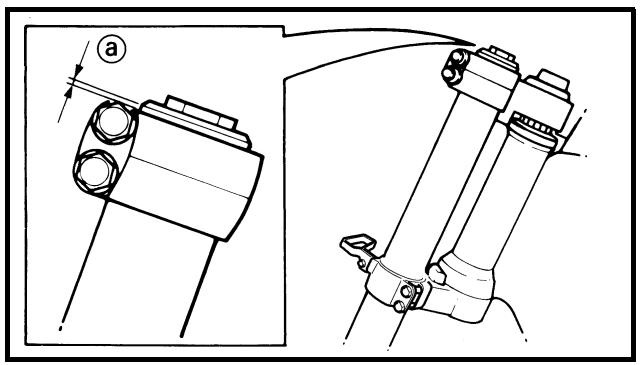
natural_image
Technical line drawing of mechanical components with no visible text or symbols
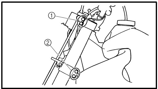
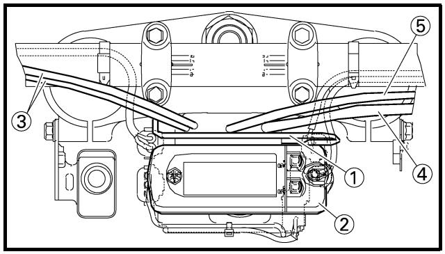
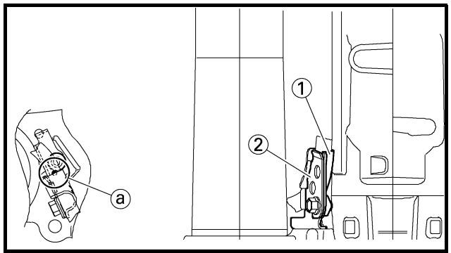
9. Install:
- Plain washer ①
- Steering shaft nut ②
- After tightening the nut, check the steering for smooth movement. If not, adjust the steering by loosening the ring nut little by little.
11. Adjust:
- Front fork top end ⓐ

Front fork top end (standard) ⓐ: Zero mm (Zero in)
12. Tighten:
- Pinch bolt (handle crown) ①
- Pinch bolt (under bracket) ②
Tighten the under bracket to specified torque. If torqued too much, it may cause the front fork to malfunction.
13. Install:
- Multi-function meter bracket ①
7 Nm (0.7 m · kg, 5.1 ft · lb)
- Multi-function meter ②
4 Nm (0.4 m · kg, 2.9 ft · lb)
NOTE:
Pass the throttle cables ③, clutch cable ④ and hot starter cable ⑤ between the multi-function meter bracket and handle crown.
14. Install:
- Holder ① | 13 Nm (1.3 m · kg, 9.4 ft · lb)
- Clamp ② 7 Nm (0.7 m · kg, 5.1 ft · lb)
NOTE:
- Install so that the marking @ on the speed sensor lead aligns with the holder edge.
- Fasten the speed sensor lead to the holder with the clamp.
9. Monter:
Extent of removal: removal
① Swingarm
| Extent of removal | Order | Part name | Q'ty | Remarks |
| Preparation for removal | | SWINGARM REMOVALHold the machine by placing the suitable stand under the engine.Brake hose holderRear caliperBolt (brake pedal)Drive chain | | WARNINGSupport the machine securely so there is no danger of it falling over.Refer to “FRONT BRAKE AND REAR BRAKE” section.Shift the brake pedal backward. |
| 1 | Chain support | 1 | Hold the swingarm. |
| 2 | Chain tensioner (lower) | 1 |
| 3 | Bolt (rear shock absorber-relay arm) | 1 |
| 4 | Bolt (connecting rod) | 1 |
| 5 | Pivot shaft | 1 |
| 6 | Swingarm | 1 |
BRAS OSCILLANT
Extent of removal:
① Swingarm disassembly
② Connecting rod removal and disassembly
③ Relay arm removal and disassembly
| Extent of removal | Order | Part name | Q'ty | Remarks |
| | SWINGARM DISASSEMBLY | | |
| 1 | Cap | 2 | Refer to “REMOVAL POINTS”. |
| 2 | Relay arm | 1 | |
| 3 | Connecting rod | 1 | |
| 4 | Collar | 2 | |
| 5 | Oil seal | 2 | |
| 6 | Thrust bearing | 2 | |
| 7 | Bush | 2 | |
| 8 | Oil seal | 8 | |
| 9 | Bearing | 10 | Refer to “REMOVAL POINTS”. |
DEMONTAGE DU BRAS OSCILLANT
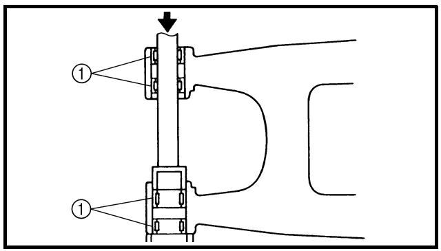
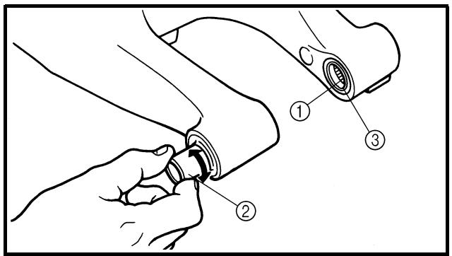
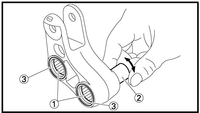
EC573000
REMOVAL POINTS
Cap
- Remove:
- Cap (left) ①
NOTE:
Remove with a slotted-head screwdriver inserted under the mark ⓐ on the cap (left).
EC573200
Bearing
- Remove:
- Bearing ①
NOTE:
Remove the bearing by pressing its outer race.
EC574010
INSPECTION
Wash the bearings, bushes and collars in a solvent.
EC574111
Swingarm
-
Inspect:
-
Bearing ①
- Bush ②
Free play exists/unsmooth revolution/rust → Replace bearing and bush as a set.
- Inspect:
- Oil seal ③
Damage → Replace.
Relay arm
-
Inspect:
-
Bearing ①
- Collar ②
Free play exists/unsmooth revolution/rust → Replace bearing and collar as a set.
- Inspect:
- Oil seal ③
Damage → Replace.
POINTS DE DEPOSE
Capuchon
- Déposer:
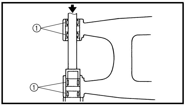
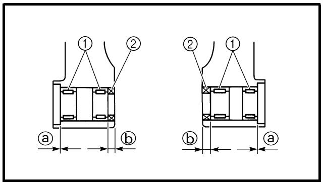
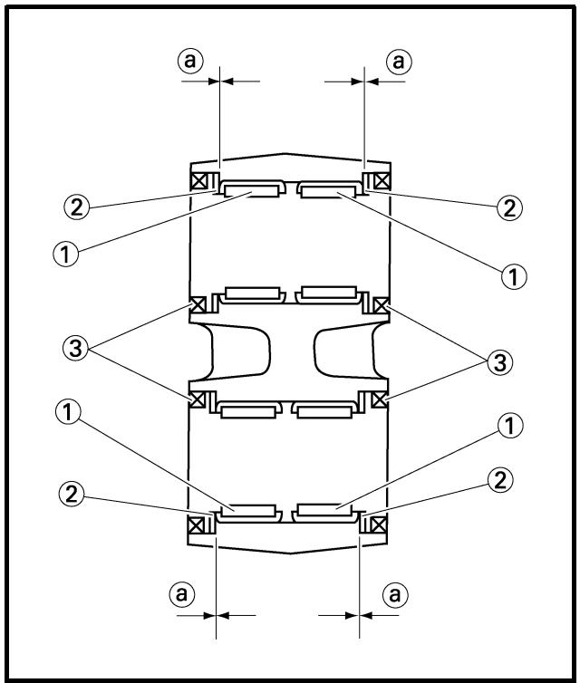
Connecting rod
1. Inspect:
Free play exists/unsmooth revolution/rust → Replace bearing and collar as a set.
2. Inspect:
- Oil seal ③
Damage → Replace.
EC575000
ASSEMBLY AND INSTALLATION
Bearing and oil seal
1. Install:
To swingarm.
NOTE:
- Apply the molybdenum disulfide grease on the bearing when installing.
- Install the bearing by pressing it on the side having the manufacture's marks or numbers.
- First install the outer and then the inner bearings to a specified depth from inside.

Installed depth of bearings:
Outer ⓐ: Zero mm (Zero in)
Inner ⓑ: 6.5 mm (0.26 in)
2. Install:
- Bearing ①
- Plain washer ②
- Oil seal ③
To relay arm.
NOTE:
- Apply the molybdenum disulfide grease on the bearing when installing.
- Install the bearing by pressing it on the side having the manufacture's marks or numbers.
- Apply the molybdenum disulfide grease on the plain washer.

Installed depth of bearings ⓐ:
Zero mm (Zero in)
Bielle
3. Install:
To connecting rod.
NOTE:
- Apply the molybdenum disulfide grease on the bearing when installing.
- Install the bearing by pressing it on the side having the manufacture's marks or numbers.

Installed depth of bearings ⓐ: Zero mm (Zero in)
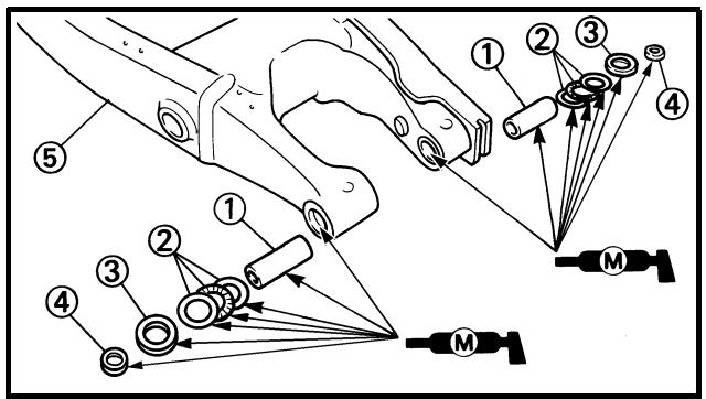
Swingarm
1. Install:
- Bush ①
- Thrust bearing ②
- Oil seal ③
- Collar ④
To swingarm ⑤.
NOTE:
Apply the molybdenum disulfide grease on the bushes, thrust bearings, oil seal lips and contact surfaces of the collar and thrust bearing.
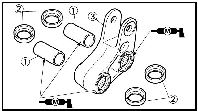
2. Install:
- Collar ①
- Washer ②
To relay arm ③.
NOTE:
Apply the molybdenum disulfide grease on the collars and oil seal lips.
3. Monter:
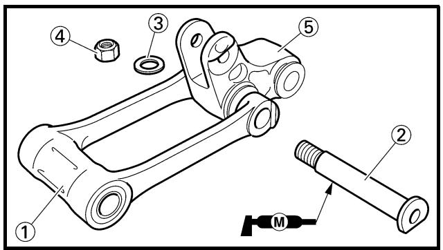
3. Install:
- Collar ①
To connecting rod ②.
NOTE:
Apply the molybdenum disulfide grease on the collar and oil seal lips.
4. Install:
- Connecting rod ①
- Bolt (connecting rod) ②
- Plain washer ③
- Nut (connecting rod) ④
80 Nm (8.0 m · kg, 58 ft · lb)
To relay arm ⑤.
NOTE:
Apply the molybdenum disulfide grease on the bolt.
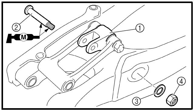
5. Install:
- Relay arm ①
- Bolt (relay arm) ②
- Plain washer ③
- Nut (relay arm) ④
To swingarm.
NOTE:
- Apply the molybdenum disulfide grease on the bolt circumference and threaded portion.
- Do not tighten the nut yet.
3. Monter:
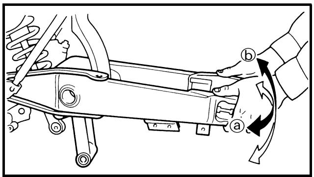
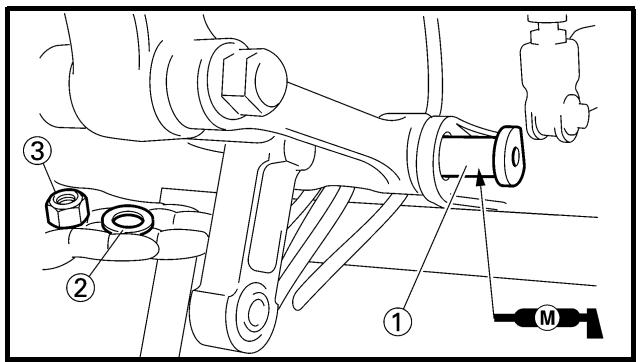
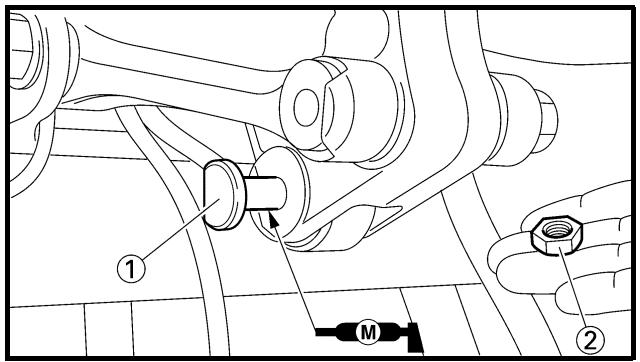
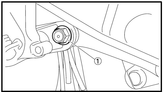
natural_image
Technical line drawing of a mechanical assembly with labeled component (1), no readable text or symbols present
6. Install:
85 Nm (8.5 m · kg, 61 ft · lb)
NOTE:
- Apply the molybdenum disulfide grease on the pivot shaft.
- Insert the pivot shaft from right side.
7. Check:
- Swingarm side play ⓐ
Free play exists → Replace thrust bearing.
- Swingarm up and down movement ⑥ Unsmooth movement/binding/rough spots → Grease or replace bearings, bushes and collars.
8. Install:
- Bolt (connecting rod) ①
- Plain washer ②
- Nut (connecting rod) ③
NOTE:
- Apply the molybdenum disulfide grease on the bolt.
- Do not tighten the nut yet.
9. Install:
- Bolt (rear shock absorber-relay arm) ①
- Nut (rear shock absorber-relay arm) ②
53 Nm (5.3 m · kg, 38 ft · lb)
NOTE:
Apply the molybdenum disulfide grease on the bolt.
10. Tighten:
- Nut (connecting rod) ①
80 Nm (8.0 m · kg, 58 ft · lb)
6. Monter:
- Bras oscillant ①
- Boulon-pivot ②
85 Nm (8,5 m · kg, 61 ft · lb)
N.B.:
natural_image
Technical line drawing of a mechanical assembly with labeled component (1), no readable text or symbols present
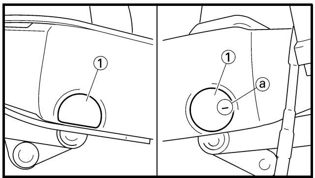

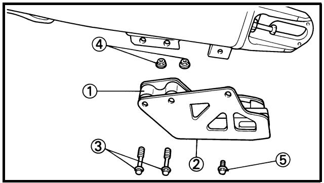
11. Tighten:
- Nut (relay arm) ①
70 Nm (7.0 m · kg, 50 ft · lb)
12. Install:
- Cap ①
NOTE:
Install the cap (right) with its mark ⓐ facing forward.
13. Install:
- Bolt [chain tensioner (lower)] ①
- Plain washer ②
- Collar ③
- Chain tensioner ④
- Nut [chain tensioner (lower)] ⑤
16 Nm (1.6 m · kg, 11 ft · lb)
14. Install:
- Chain support ①
- Support cover ②
- Bolt {chain support [ = 50 mm (1.97 in)]}
③
- Nut (chain support) ④
7 Nm (0.7 m · kg, 5.1 ft · lb)
- Bolt {support cover [ = 10 mm (0.39 in)]}
⑤ 7 Nm (0.7 m · kg, 5.1 ft · lb)
11. Serrer:
Extent of removal:
① Rear shock absorber removal
② Rear shock absorber disassembly
| Extent of removal | Order | Part name | Q'ty | Remarks |
| Preparation for removal | | REAR SHOCK ABSORBER REMOVALHold the machine by placing the suitable stand under the engine.Seat and side coversSilencerDrain the coolant.Catch tank breather hoseCatch tank hoseAir induction hose (air cut-off valve-air filter case) | | WARNINGSupport the machine securely so there is no danger of it falling over.Refer to “SEAT, FUEL TANK AND SIDE COVERS” section in the CHAPTER 4.Refer to “EXHAUST PIPE AND SILENCER” section in the CHAPTER 4.Refer to “COOLANT REPLACEMENT” section in the CHAPTER 3.Disconnect at the catch tank side.Disconnect at the catch tank side.Disconnect at the air filter case side. |
AMORTISSEUR ARRIERE
| Extent of removal | Order | Part name | Q'ty | Remarks |
| | Cylinder head breather hoseBatteryDisconnect the starter relay coupler.Starter motor lead | | Disconnect at the air filter case side.Refer to “BATTERY INSPECTION AND CHARGING” section in the CHAPTER 3.Disconnect at the starter relay side. |
| 1 | 2 | 1 | Locking tie | 4 | |
| 2 | Taillight coupler | 1 | |
| 3 | CDI unit coupler | 3 | |
| 4 | Plastic band | 1 | |
| 5 | Clamp (air filter joint) | 1 | Only loosening. |
| 6 | Rear frame | 1 | |
| 7 | Bolt (rear shock absorber-relay arm) | 1 | Hold the swingarm. |
| 8 | Bolt (rear shock absorber-frame) | 1 | |
This shock absorber is provided with a separate type tank filled with high-pressure nitrogen gas. To prevent the danger of explosion, read and understand the following information before handling the shock absorber.
The manufacturer can not be held responsible for property damage or personal injury that may result from improper handling.
- Never tamper or attempt to disassemble the cylinder or the tank.
- Never throw the shock absorber into an open flame or other high heat. The shock absorber may explode as a result of nitrogen gas expansion and/or damage to the hose.
- Be careful not to damage any part of the gas tank. A damaged gas tank will impair the damping performance or cause a malfunction.
- Take care not to scratch the contact surface of the piston rod with the cylinder; or oil could leak out.
- Never attempt to remove the plug at the bottom of the nitrogen gas tank. It is very dangerous to remove the plug.
- When scrapping the shock absorber, follow the instructions on disposal.
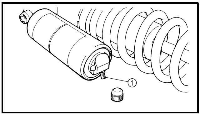
natural_image
Technical illustration of a mechanical assembly with coiled spring and housing (no text or symbols)
EC587000
NOTES ON DISPOSAL (YAMAHA DEALERS ONLY)
Before disposing the shock absorber, be sure to extract the nitrogen gas from valve ①. Wear eye protection to prevent eye damage from escaping gas and/or metal chips.
WARNING
To dispose of a damaged or worn-out shock absorber, take the unit to your Yamaha dealer for this disposal procedure.
REMARQUES CONCERNANT LA MANIPULATION
! AVERTISSEMENT
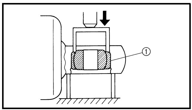
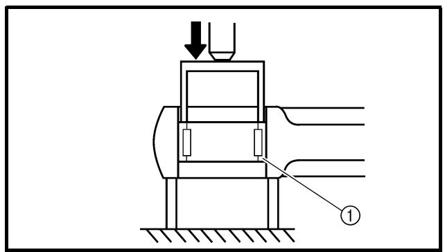
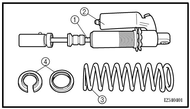
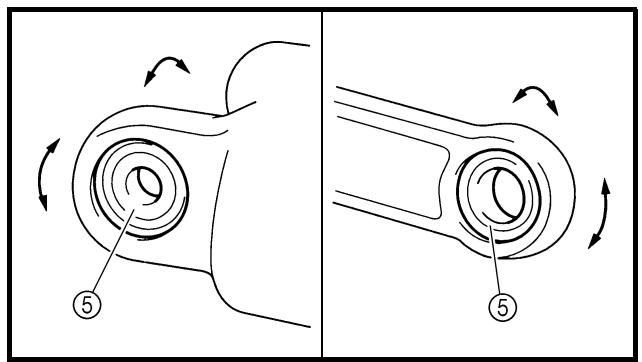
EC583000
REMOVAL POINTS
EC583320
Bearing
1. Remove:
- Stopper ring (upper bearing) ①
NOTE:
Press in the bearing while pressing its outer race and remove the stopper ring.
2. Remove:
- Upper bearing ①
NOTE: ____
Remove the bearing by pressing its outer race.
3. Remove:
- Lower bearing ①
NOTE:
Remove the bearing by pressing its outer race.
EC584000
INSPECTION
Rear shock absorber
1. Inspect:
- Damper rod ①
Bends/damage → Replace absorber assembly.
- Shock absorber ②
Oil leaks → Replace absorber assembly.
Gas leaks → Replace absorber assembly.
- Spring ③
Damage → Replace spring.
Fatigue → Replace spring.
Move spring up and down.
- Spring guide ④
Wear/damage → Replace spring guide.
- Bearing ⑤
Free play exists/unsmooth revolution/rust → Replace.
POINTS DE DEPOSE
Roulement
- Déposer:
EC585000
ASSEMBLY AND INSTALLATION
EC585300
Bearing
- Install:
- Upper bearing ①
NOTE:
Install the bearing parallel until the stopper ring groove appears by pressing its outer race.
CAUTION:
Do not apply the grease on the bearing outer race because it will wear the rear shock absorber surface on which the bearing is press fitted.
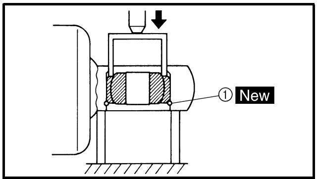
- Install:
- Stopper ring (upper bearing) ① New
NOTE:
After installing the stopper ring, push back the bearing until it contacts the stopper ring.
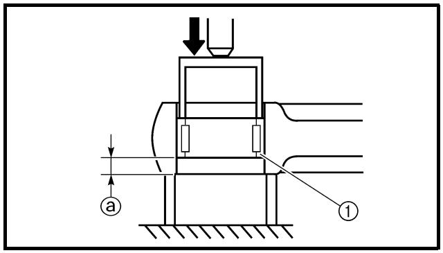
- Install:
- Lower bearing ①
NOTE:
Install the bearing by pressing it on the side having the manufacture's marks or numbers.

Installed depth of the bearing ⓐ: 4 mm (0.16 in)
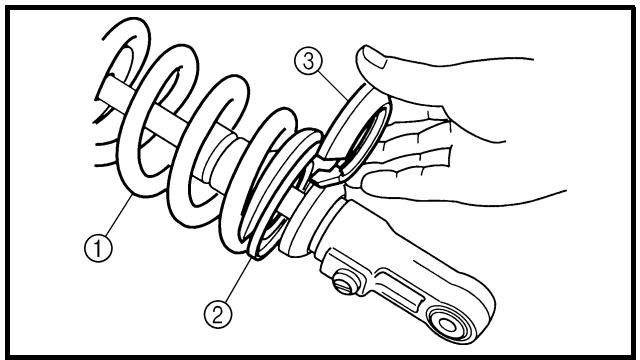
EC585111
Spring (rear shock absorber)
-
Install:
-
Spring ①
- Spring guide (upper) ②
- Spring guide (lower) ③
ASSEMBLAGE ET MONTAGE
Roulement
- Monter:
natural_image
Technical illustration of a mechanical spring assembly with labeled component (1), no text or symbols present
2. Tighten:
- Adjuster ①
3. Adjust:
- Spring length (installed)
Refer to “REAR SHOCK ABSORBER SPRING PRELOAD ADJUSTMENT” section in the CHAPTER 3.
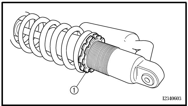
natural_image
Technical illustration of a mechanical spring assembly with labeled component (1), no text or symbols present
4. Tighten:
- Locknut ①
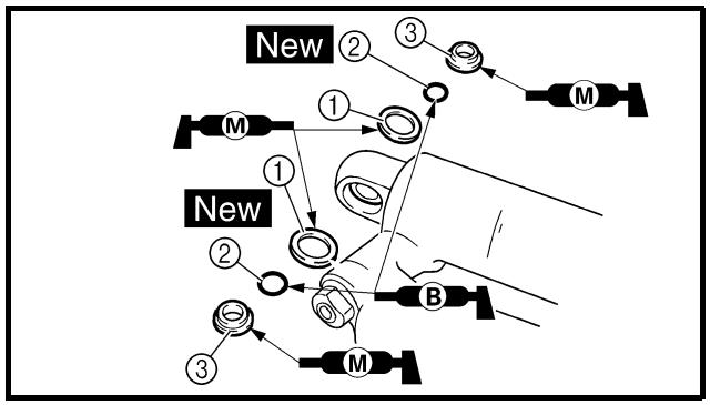
flowchart
graph TD
    A["1"] --> B["2"]
    B --> C["3"]
    C --> D["M"]
    E["2"] --> F["3"]
    F --> G["M"]
    H["1"] --> I["2"]
    I --> J["3"]
    J --> K["M"]
    L["1"] --> M["2"]
    M --> N["3"]
    N --> O["M"]
    P["1"] --> Q["2"]
    Q --> R["M"]
    S["1"] --> T["3"]
    T --> U["M"]
    V["1"] --> W["2"]
    W --> X["M"]
    Y["1"] --> Z["3"]
    Z --> AA["M"]
Rear shock absorber
1. Install:
- Dust seal ①
- O-ring ②
- Collar ③

NOTE:
- Apply the molybdenum disulfide grease on the dust seal lips and collars.
- Apply the lithium soap base grease on the O-rings.
2. Serrer:
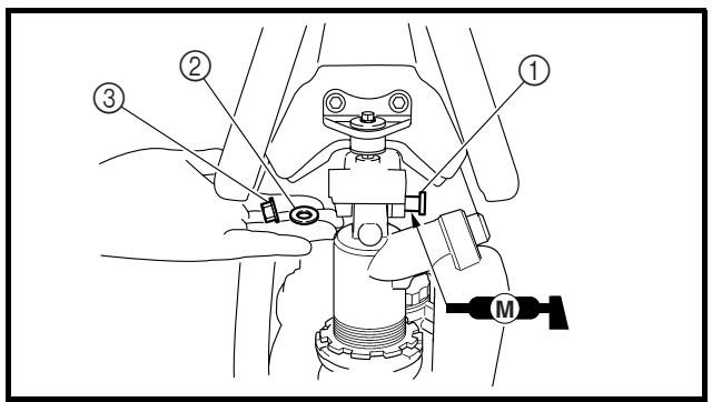
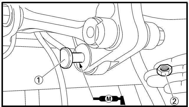
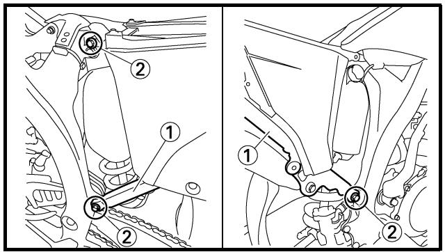
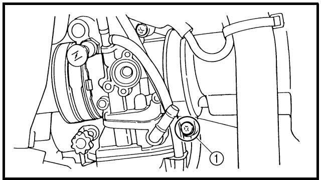
2. Install:
- Bush ①
- Collar ②
- Dust seal ③
NOTE:
- Apply the molybdenum disulfide grease on the bearing and dust seal lips.
- Install the dust seals with their lips facing outward.
3. Install:
- Rear shock absorber
4. Install:
- Bolt (rear shock absorber-frame) ①
- Washer ②
- Nut (rear shock absorber-frame) ③
56 Nm (5.6 m · kg, 40 ft · lb)
NOTE:
Apply the molybdenum disulfide grease on the bolt.
5. Install:
- Bolt (rear shock absorber-relay arm) ①
- Nut (rear shock absorber-relay arm) ②
53 Nm (5.3 m · kg, 38 ft · lb)
NOTE:
Apply the molybdenum disulfide grease on the bolt.
6. Install:
- Rear frame ①
- Bolt [rear frame (upper)] ②
38 Nm (3.8 m · kg, 27 ft · lb)
32 Nm (3.2 m · kg, 23 ft · lb)
- Bolt [rear frame (lower)] ③
7. Tighten:
- Screw (air filter joint) ①
3 Nm (0.3 m · kg, 2.2 ft · lb)
2. Monter:
- Plastic band
- Taillight coupler
- Locking tie
8. Monter:
① Headlight
② Multi-function display
③ “ENGINE STOP” button
④ Clutch switch
⑤ Diode
⑥ Starter relay diode
⑦ TPS (throttle position sensor)
⑧ Starter relay
⑨ Fuse
⑩ Starting circuit cut-off relay
⑪ CDI unit
⑫ Taillight
⑬ Neutral switch
⑭ Starter motor
⑮ AC magneto
⑯ Rectifier/regulator
⑰ Ignition coil
⑱ Spark plug
⑲ Start switch
⑳ Main switch
②1 Speed sensor
② Battery
COLOR CODE
B .... Black
Br .... Brown
Ch......Chocolate
Dg ...... Dark green
G....Green
Gy ...... Gray
L......Blue
O....Orange
R....Red
Sb ...... Sky blue
W ...... White
Y......Yellow
B/L ...... Black/Blue
B/W...... Black/White
L/B ...... Blue/Black
L/R......Blue/Red
L/Y ...... Blue/Yellow
L/W ...... Blue/White
R/B......Red/Black
R/W......Red/White
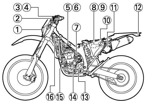
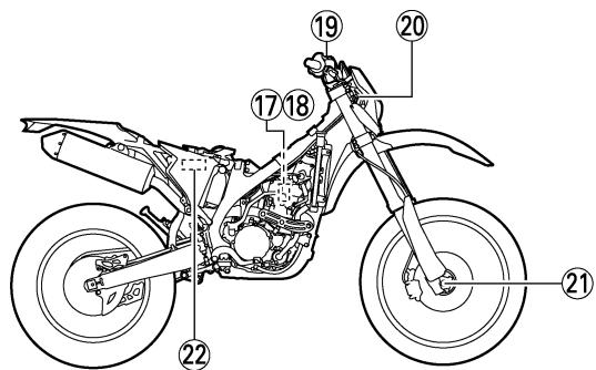
EC612000
WIRING DIAGRAM
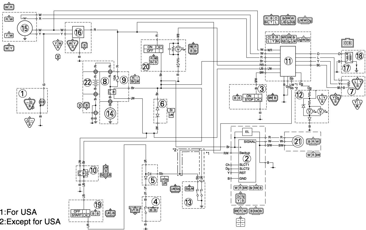
flowchart
graph TD
    subgraph "1: For USA"
        A["1"] --> B["2"]
        C["3"] --> D["4"]
        E["5"] --> F["6"]
        G["7"] --> H["8"]
        I["9"] --> J["10"]
        K["11"] --> L["12"]
        M["13"] --> N["14"]
        O["15"] --> P["16"]
        Q["17"] --> R["18"]
    end

    subgraph "Except for USA"
        S["1"] --> T["2"]
        U["3"] --> V["4"]
        W["6"] --> X["7"]
        Y["9"] --> Z["10"]
        AA["11"] --> AB["12"]
        AC["13"] --> AD["14"]
        AE["15"] --> AF["16"]

    subgraph "Signal"
        AG["21"] --> AH["22"]
        AI["3"] --> AJ["6"]
        AK["4"] --> AL["7"]
        AM["5"] --> AN["8"]
        AO["6"] --> AP["9"]
        AQ["7"] --> AR["10"]
        AS["8"] --> AT["11"]
        AU["9"] --> AV["12"]
    end

    subgraph "Backup"
        AW["2"] --> AX["3"]
        AY["W"] --> AZ["B"]
        BA["R"] --> BB["B"]
        BC["RW"] --> BD["B"]
        BE["BW"] --> BF["BW"]
        BG["W"] --> BH["W"]
    end

    subgraph "Output"
        BI["R"] --> BJ["W"]
        BK["RW"] --> BL["W"]
    end

    subgraph "Control Signals"
        BM["R"] --> BN["W"]
        BO["RW"] --> BP["W"]
    end

    style 1 fill:#f9f,stroke:#333
    style 2 fill:#f9f,stroke:#333
    style 3 fill:#f9f,stroke:#333
    style 4 fill:#f9f,stroke:#333
    style 5 fill:#f9f,stroke:#333
    style 6 fill:#f9f,stroke:#333
    style 7 fill:#f9f,stroke:#333
    style 8 fill:#f9f,stroke:#333
    style 9 fill:#f9f,stroke:#333
    style 10 fill:#f9f,stroke:#333
    style 11 fill:#f9f,stroke:#333
    style 12 fill:#f9f,stroke:#333
    style 13 fill:#f9f,stroke:#333
    style 14 fill:#f9f,stroke:#333
    style 15 fill:#f9f,stroke:#333
    style 16 fill:#f9f,stroke:#333
    style 17 fill:#f9f,stroke:#333
    style 18 fill:#f9f,stroke:#333
    style 19 fill:#f9f,stroke:#333
    style 20 fill:#f9f,stroke:#333
    style 21 fill:#f9f,stroke:#333
    style 22 fill:#f9f,stroke:#333
    style 23 fill:#f9f,stroke:#333
    style 24 fill:#f9f,stroke:#333
    style 25 fill:#f9f,stroke:#333
    style 26 fill:#f9f,stroke:#333
    style 27 fill:#f9f,stroke:#333
    style 28 fill:#f9f,stroke:#333
    style 29 fill:#f9f,stroke:#333
    style 30 fill:#f9f,stroke:#333
    style 31 fill:#f9f,stroke:#333
    style 32 fill:#f9f,stroke:#333
    style 33 fill:#f9f,stroke:#333
    style 34 fill:#f9f,stroke:#333
    style 35 fill:#f9f,stroke:#333
    style 36 fill:#f9f,stroke:#333
    style 37 fill:#f9f,stroke:#333
    style 38 fill:#f9f,stroke:#333
    style 39 fill:#f9f,stroke:#333
    style 40 fill:#f9f,stroke:#333
    style 41 fill:#f9f,stroke:#333
    style 42 fill:#f9f,stroke:#333
    style 43 fill:#f9f,stroke:#333
    style 44 fill:#f9f,stroke:#333
    style 45 fill:#f9f,stroke:#333
    style 46 fill:#f9f,stroke:#333
    style 47 fill:#f9f,stroke:#333
    style 48 fill:#f9f,stroke:#333
    style 49 fill:#f9f,stroke:#333
    style 50 fill:#f9f,stroke:#333
*1:For USA
*2: Except for USA
PARTIE ELECTRIQUE COMPOSANTS ELECTRI- QUES ET SCHEMA DE CABLAGE
COMPOSANTS ELECTRIQUES
① Phare
⑳ Interruptor principal
Use the following steps for checking the possibility of the malfunctioning engine being attributable to ignition system failure and for checking the spark plug which will not spark.
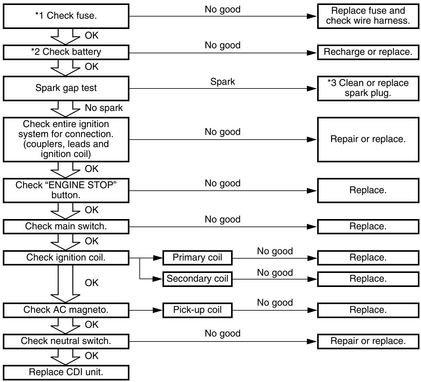
flowchart
graph TD
    A["*1 Check fuse."] -->|OK| B["*2 Check battery"]
    B -->|OK| C["Spark gap test"]
    C -->|No spark| D["Check entire ignition system for connection. (couplers, leads and ignition coil)"]
    D -->|OK| E["Check "ENGINE STOP" button."]
    E -->|OK| F["Check main switch."]
    F -->|OK| G["Check ignition coil."]
    G -->|OK| H["Check AC magneto."]
    H -->|OK| I["Check neutral switch."]
    I -->|OK| J["Replace CDI unit."]

    K["Replace fuse and check wire harness."] --> L["Recharge or replace."]
    L --> M["*3 Clean or replace spark plug."]
    M --> N["Repair or replace."]

    O["No good"] --> P["No good"]
    Q["No good"] --> R["No good"]
    S["No good"] --> T["No good"]
    U["No good"] --> V["No good"]
    W["No good"] --> X["No good"]

    Y["No good"] --> Z["No good"]
    AA["No good"] --> AB["No good"]

    AC["Replace."] --> AD["Replace."]
    AE["No good"] --> AF["No good"]
    AG["No good"] --> AH["No good"]

    AI["Primary coil"] --> AJ["Secondary coil"]
    AK["No good"] --> AL["No good"]
    AM["Replace."] --> AN["Replace."]
    AO["No good"] --> AP["No good"]

    AQ["Pick-up coil"] --> AR["Repair or replace."]
*1 marked: Refer to “FUSE INSPECTION” section in the CHAPTER 3.
*2 marked: Refer to “BATTERY INSPECTION AND CHARGING” section in the CHAPTER 3.
*3 marked: Only when the ignition checker is used.
NOTE:
- Remove the following parts before inspection.
1) Seat
2) Fuel tank
- Use the following special tools in this inspection.
Dynamic spark tester:
YM-34487
Ignition checker:
90890-06754

Pocket tester:
YU-3112-C/90890-03112
SYSTEME D'ALLUMAGE
ETAPES DU CONTROLE
natural_image
Cross-sectional technical diagram of a mechanical assembly (no text or labels)
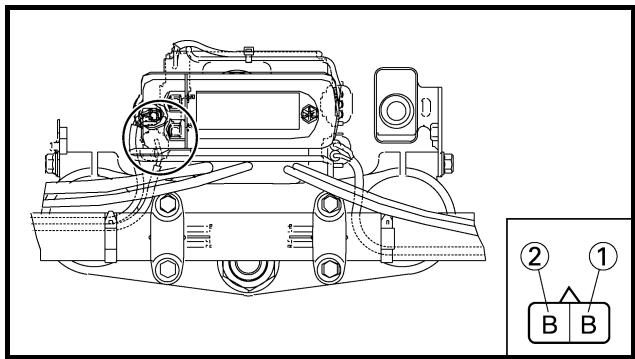
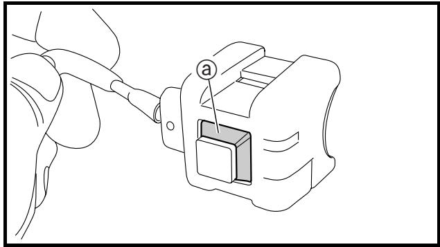
natural_image
Line drawing of a cable being inserted into a device with a labeled component (a), no text or symbols present.
SPARK GAP TEST
- Disconnect the ignition coil from spark plug.
- Remove the ignition coil cap.
-
Connect the dynamic spark tester ① (ignition checker ②) as shown.
-
Ignition coil ③
- Spark plug ④
A For USA and CDN
B Except for USA and CDN
- Kick the kickstarter.
- Check the ignition spark gap.
- Start engine, and increase spark gap until misfire occurs. (for USA and CDN only)

Minimum spark gap: 6.0 mm (0.24 in)
COUPLERS, LEADS AND IGNITION COIL CONNECTION INSPECTION
-
Check:
-
Couplers and leads connection Rust/dust/looseness/short-circuit → Repair or replace.
- Ignition coil and spark plug as they are fitted
Push in the ignition coil until it closely contacts the spark plug hole in the cylinder head cover.
EC625001
- Inspect:
- “ENGINE STOP” button conduct
| Tester (+) lead → Black lead 1 |
| Tester (−) lead → Black lead 2 |
| | B1 | B2 | Tester selec-tor position |
| PUSH IN | | | Ω×1 |
| FREE | | |
No continuity while being pushed → Replace.
Continuity while being freed → Replace.
- Inspect:
- Rubber part ⓐ
Tears/damage → Replace.
TEST DE LA LONGUEUR D'ETINCELLE
natural_image
Line drawing of a hand holding a handheld device with a circular button and labeled part (a), no text or symbols present.
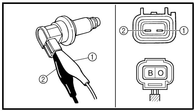
MAIN SWITCH INSPECTION
1. Inspect:
- Main switch conduct
| Tester (+) lead → Red lead 1 |
| Tester (−) lead → Brown lead 2 |
| | R1 | Br2 | Tester selec-tor position |
| ON | | | Ω × 1 |
| OFF | | |
Continuous while the main switch is moved to "OFF" → Replace.
Not continuous while the main switch is moved to “ON” → Replace.
2. Inspect:
- Main switch indicator light Use 12 V battery.
Battery (+) lead → Red/Black lead ①
Battery (−) lead → Black lead ②
Indicator light does not come on → Replace.
3. Inspect:
- Rubber part ⓐ
Tears/damage → Replace.
EC626002
IGNITION COIL INSPECTION
- Remove the ignition coil cap.
2. Inspect:
- Primary coil resistance
Out of specification → Replace.
| Tester (+) lead → Orange lead 1 |
| Tester (−) lead → Black lead 2 |
 | Primary coil resistance | Tester selector position |
| 0.08 ~ 0.10 Ω at 20 °C (68 °F) | Ω × 1 |
1. Contrôler:
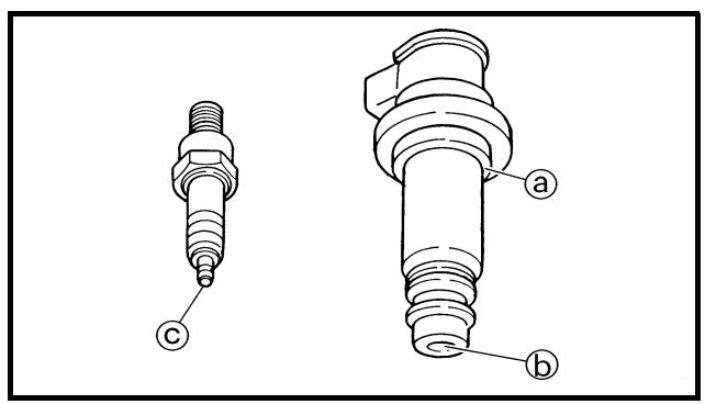
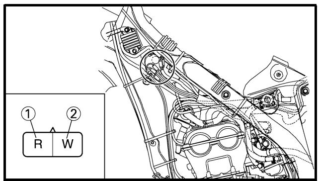
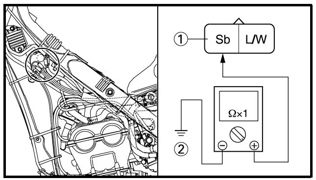
3. Inspect:
• Secondary coil resistance
Out of specification → Replace.
| Tester (+) lead → Orange lead 1 |
| Tester (−) lead → Spark plug terminal 2 |
| Secondary coil resistance | Tester selector position |
| 4.6 ~ 6.8 kΩ at 20 °C (68 °F) | kΩ × 1 |
4. Inspect:
- Sealed portion of ignition coil ⓐ
- Spark plug terminal pin ⑥
- Threaded portion of spark plug © Wear → Replace.
AC MAGNETO INSPECTION
1. Inspect:
- Pick-up coil resistance
Out of specification → Replace.
| Tester (+) lead → Red lead 1 |
| Tester (−) lead → White lead 2 |
| Pick-up coil resistance | Tester selector position |
| 248 ~ 372 Ω at 20 °C (68 °F) | Ω × 100 |
NEUTRAL SWITCH INSPECTION
1. Inspect:
- Neutral switch conduct
| Tester (+) lead → Sky blue lead 1 |
| Tester (−) lead → Ground 2 |
| | Sb1 | Ground2 | Tester selec-tor position |
| NEUTRAL | | | Ω × 1 |
| IN GEAR | | |
No continuity while in neutral → Replace.
Continuity while in gear → Replace.
EC628000
CDI UNIT INSPECTION
Check all electrical components. If no fault is found, replace the CDI unit. Then check the electrical components again.
3. Contrôler:
If the main switch is set to "ON", the starter motor can only operate if at least one of the following conditions is met:
- The transmission is in neutral (the neutral switch is closed).
- The clutch lever is pulled to the handlebar (the clutch switch is closed).
The starting circuit cut-off relay prevents the starter motor from operating when neither of these conditions has been met. In this instance, the starting circuit cut-off relay is open so current cannot reach the starter motor. When at least one of the above conditions has been met the starting circuit cut-off relay is closed and the engine can be started by pressing the start switch.

WHEN THE TRANSMISSION IS IN NEUTRAL
WHEN THE CLUTCH LEVER IS
PULLED TO THE HANDLEBAR
① Battery
② Main fuse
③ Main switch
④ Starting circuit cut-off relay
⑤ Start switch
⑥ Diode
⑦ Clutch switch
⑧ Neutral switch
⑨ Starter relay
⑩ Starter motor
DEMARRAGE
ELECTRIQUE
FONCTIONNEMENT DU DISPOSITIF DE COUPURE DU CIRCUIT DE DEMARRAGE
If the starter motor will not operate, use the following inspection steps.
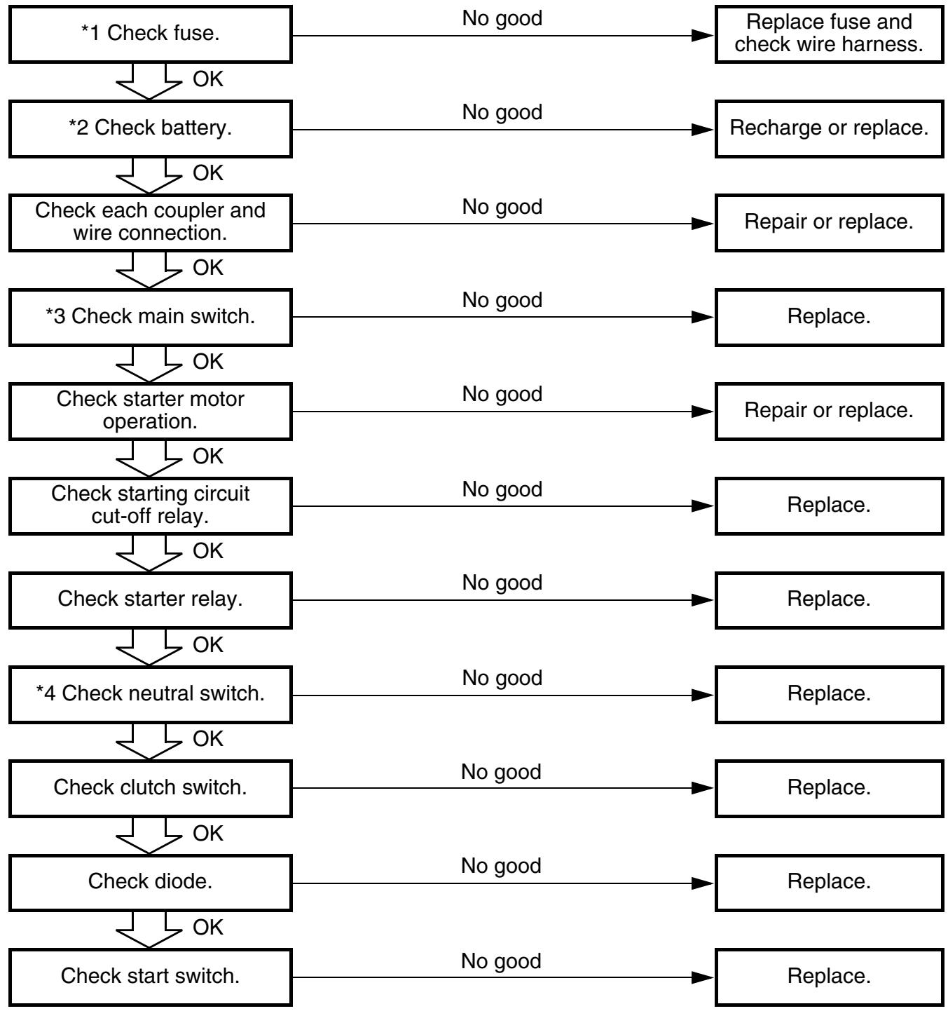
flowchart
graph TD
    A["*1 Check fuse."] -->|OK| B["*2 Check battery."]
    B -->|OK| C["Check each coupler and wire connection."]
    C -->|OK| D["*3 Check main switch."]
    D -->|OK| E["Check starter motor operation."]
    E -->|OK| F["Check starting circuit cut-off relay."]
    F -->|OK| G["Check starter relay."]
    G -->|OK| H["*4 Check neutral switch."]
    H -->|OK| I["Check clutch switch."]
    I -->|OK| J["Check diode."]
    J -->|OK| K["Check start switch."]
    A -->|No good| L["Replace fuse and check wire harness."]
    B -->|No good| M["Recharge or replace."]
    C -->|No good| N["Repair or replace."]
    D -->|No good| O["Replace."]
    E -->|No good| P["Repair or replace."]
    F -->|No good| Q["Replace."]
    G -->|No good| R["Replace."]
    H -->|No good| S["Replace."]
    I -->|No good| T["Replace."]
    J -->|No good| U["Replace."]
    K -->|No good| V["Replace."]
*1 marked: Refer to "FUSE INSPECTION" section in the CHAPTER 3.
*2 marked: Refer to “BATTERY INSPECTION AND CHARGING” section in the CHAPTER 3.
*3 marked: Refer to "MAIN SWITCH INSPECTION" section.
*4 marked: Refer to “NEUTRAL SWITCH INSPECTION” section.
NOTE:
- Remove the following parts before inspection.
1) Seat
2) Rear fender
- Use 12 V battery in this inspection.
- Use the following special tools in this inspection.
Pocket tester:
YU-3112-C/90890-03112
ETAPES DU CONTROLE
- Couplers and leads connection Rust/dust/looseness/short-circuit → Repair or replace.
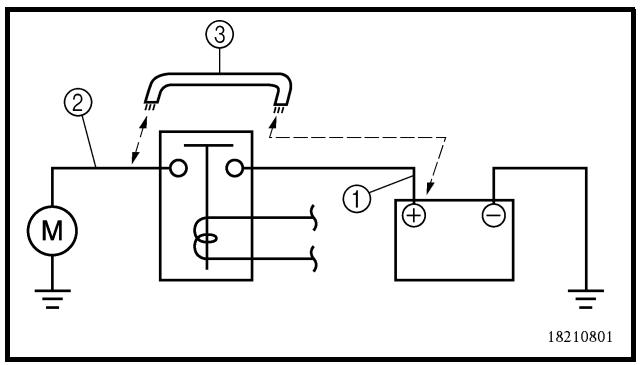
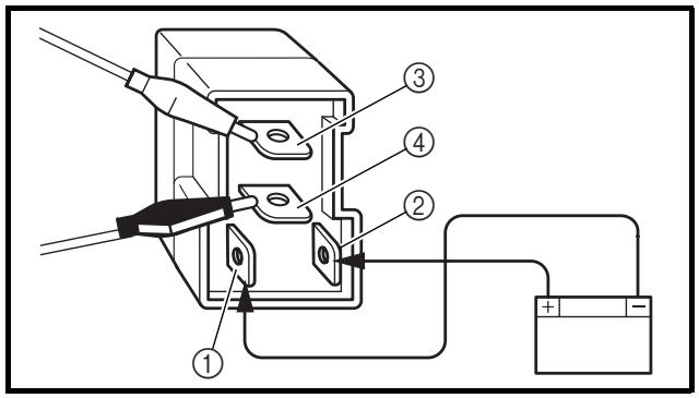
- Connect the positive battery terminal ① and starter motor lead ② with a jumper lead ③.
Not operate → Repair or replace the starter motor.

WARNING
- A wire that is used as a jumper lead must have at least the same capacity or more as that of the battery lead, otherwise the jumper lead may burn.
- This check is likely to produce sparks, therefore make sure nothing flammable is in the vicinity.
STARTING CIRCUIT CUT-OFF RELAY INSPECTION
1. Remove:
- Starting circuit cut-off relay
2. Inspect:
- Starting circuit cut-off relay conduct Use 12 V battery.
| Battery (+) lead → Blue/Black lead 1Battery (−) lead → Brown lead 2 |
| Tester (+) lead → Blue/White lead 3Tester (−) lead → Black lead 4 |
| | L/W3 | B4 | Tester selec-tor position |
| Con- nected to battery | | | Ω × 1 |
| Not con- nected to battery | | |
CONTROLE DES CONNEXIONS DES FICHES RAPIDES ET DES FILS
- Contrôler:
- Starter relay conduct Use 12 V battery.
| Battery (+) lead →Starter relay terminal 1Battery (−) lead →Starter relay terminal 2 |
| Tester (+) lead → Starter relay terminal 3Tester (−) lead → Starter relay terminal 4 |
| | Terminal3 | Terminal4 | Tester selector position |
| Connected to battery | | | × 1 |
| Not connected to battery | | |
Continuous while not connected to the battery Replace.
Not continuous while connected to the battery Replace.
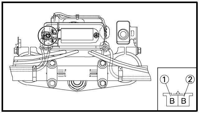
CLUTCH SWITCH INSPECTION
1. Inspect:
- Clutch switch continuity
| Tester (+) lead → Black lead 1 |
| Tester (−) lead → Black lead 2 |
| | B1 | B2 | Tester selec-tor position |
| PULL | | | Ω × 1 |
| FREE | | |
No continuous while being pulled → Replace.
Continuous while being freed → Replace.
CONTROLE DU RELAIS DE DEMARREUR
DIODE INSPECTION
- Remove the diode from wire harness.
- Inspect:
- Diode continuity
Use pocket tester (tester selection position × 1 )
| Tester (+) →Blue/Red terminal 1Tester (−) →Sky blue terminal 2 | Continuous |
| Tester (+) →Blue/Red terminal 1Tester (−) →Blue/Yellow terminal 3 | Continuous |
| Tester (+) →Sky blue terminal 2Tester (−) →Blue/Red terminal 1 | No continuous |
| Tester (+) →Blue/Yellow terminal 3Tester (−) →Blue/Red terminal 1 | No continuous |
Incorrect continuity → Replace.
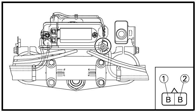
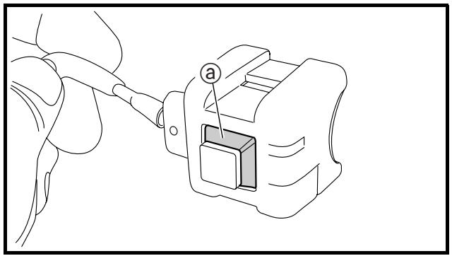
natural_image
Line drawing of a hand holding a cable with a labeled connector (no text or symbols present)
START SWITCH INSPECTION
- Inspect:
- Start switch continuity
| Tester (+) lead → Black lead 1 |
| Tester (−) lead → Black lead 2 |
| | B1 | B2 | Tester selec-tor position |
| PUSH IN | | | Ω × 1 |
| FREE | | |
No continuous while being pushed → Replace.
Continuous while being freed → Replace.
- Inspect:
- Rubber part ⓐ
Tears/damage → Replace.
CONTROLE DE LA DIODE
Extent of removal:
① Starter motor disassembly
| Extent of removal | Order | Part name | Q'ty | Remarks |
| Preparation for removal | | STARTER MOTOR REMOVALExhaust pipeStarter motor | | Refer to “EXHAUST PIPE AND SILENCER” in the CHAPTER 3. |
| | STARTER MOTOR DISASSEMBLY | | |
| 12345 | Starter motor front coverWasher (starter motor front cover)Plain washerCirclipO-ring | 11113 | |
DEMARREUR
natural_image
Technical line drawing of a mechanical component with labeled dimension (a), no readable text or symbols beyond annotations
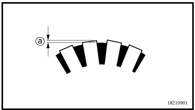
INSPECTION AND REPAIR
1. Check:
- Commutator
Dirt → Clean with 600 grit sandpaper.
2. Measure:
- Commutator diameter @
Out of specification → Replace the starter motor.

Min. commutator diameter: 16.6 mm (0.65 in)
3. Measure:
- Mica undercut ⓐ
Out of specification → Scrape the mica to the proper measurement with a hacksaw blade which has been grounded to fit the commutator.

Mica undercut: 1.5 mm (0.06 in)
NOTE:
The mica must be undercut to ensure proper operation of the commutator.
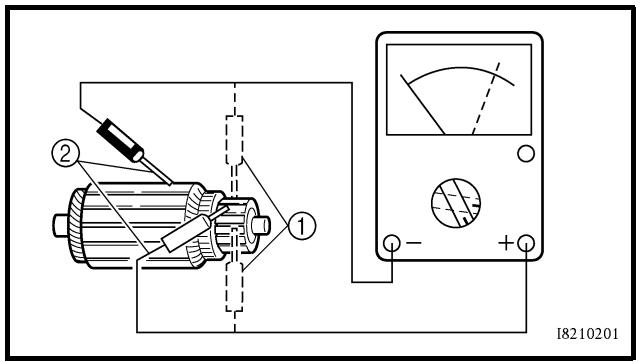
4. Measure:
- Armature assembly resistances (commutator and insulation)
Out of specification → Replace the starter motor.
| • Measure the armature assembly resistances with the pocket tester. |
 | Pocket tester:YU-03112-C/90890-03112 |
 | Armature assembly:Commutator resistance 1:0.0117 ~ 0.0143 Ω at 20 °C(68 °F)Insulation resistance 2:Above 1 MΩ at 20 °C (68 °F) |
| • If any resistance is out of specification,replace the starter motor. |
CONTROLE ET REPARATION
- Contrôler:
natural_image
Two identical spiral-shaped mechanical springs shown in line drawing style (no text or symbols)
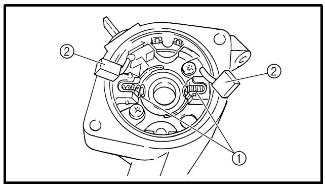
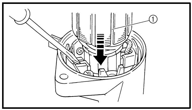
5. Measure:
- Brush length ⓐ
Out of specification → Replace the brushes as a set.

Min. brush length: 3.5 mm (0.14 in)
6. Measure:
- Brush spring force
Out of specification → Replace the brush springs as a set.

Brush spring force:
3.92 \~ 5.88 N
(400 \~ 600 gf, 14.1 \~ 21.2 oz)
ASSEMBLY
1. Install:
2. Install:
- Armature assembly ①
Install while holding down the brush using a thin screw driver.
CAUTION:
Be careful not to damage the brush during installation.
5. Mesurer:
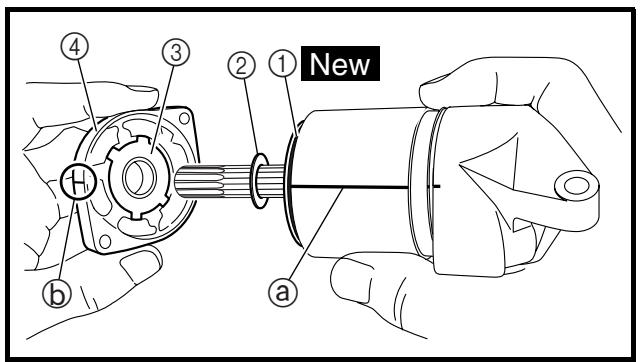
3. Install:
- O-ring ① New
- Starter motor yoke ②
NOTE:
- Align the match mark Ⓐ on the starter motor yoke with the match mark ⓑ on the starter motor rear cover.
- Install the starter motor yoke with its groove © facing rear cover.
4. Install:
- O-ring ① New
- Circlip
- Plain washer ②
- Washer (starter motor front cover) ③
- Starter motor front cover ④
NOTE:
- For installation, align the projections on the washer with the slots in the front cover.
- Align the match mark ⓐ on the starter motor yoke with the match mark ⓑ on the starter motor front cover.
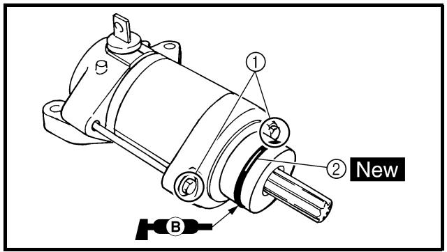
5. Install:
NOTE:
Apply the lithium soap base grease on the O-ring.
3. Monter:
If the battery is not charged, use the following inspection steps.
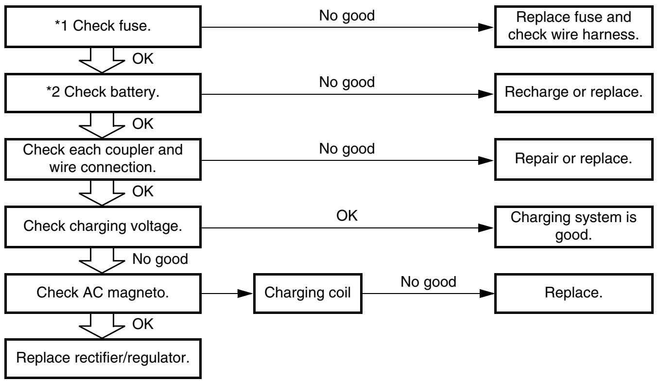
flowchart
graph TD
    A["*1 Check fuse."] -->|OK| B["*2 Check battery."]
    B -->|OK| C["Check each coupler and wire connection."]
    C -->|OK| D["Check charging voltage."]
    D -->|No good| E["Check AC magneto."]
    E -->|OK| F["Charging coil"]
    F -->|No good| G["Replace."]
    A -->|No good| H["Replace fuse and check wire harness."]
    B -->|No good| I["Recharge or replace."]
    C -->|No good| J["Repair or replace."]
    D -->|OK| K["Charging system is good."]
    E -->|No good| L["Replace rectifier/regulator."]
*1 marked: Refer to "FUSE INSPECTION" section in the CHAPTER 3.
*2 marked: Refer to “BATTERY INSPECTION AND CHARGING” section in the CHAPTER 3.
NOTE:
- Remove the following parts before inspection.
1) Seat
2) Fuel tank
- Use the following special tool in this inspection.
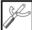
Pocket tester:
YU-3112-C/90890-03112
SYSTEME DE CHARGE
ETAPES DU CONTROLE
- Couplers and leads connection Rust/dust/looseness/short-circuit → Repair or replace.
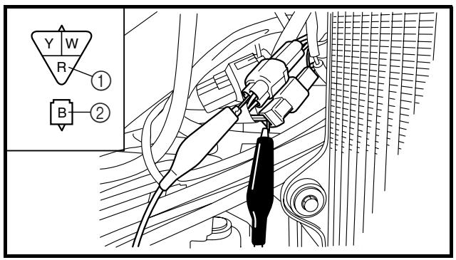
CHARGING VOLTAGE INSPECTION
- Start the engine.
- Inspect:
- Charging voltage
Out of specification → If no failure is found in checking the source coil resistance, replace the rectifier/regulator.
| Tester (+) lead → Red lead 1 |
| Tester (−) lead → Black lead 2 |
| Charging voltage | Tester selector position |
| 14.0 ~ 15.0 V at 5,000 r/min | DCV-20 |
3. Inspect:
- Charging coil resistance
Out of specification → Replace.
| Tester (+) lead → White lead 1 |
| Tester (−) lead → Ground 2 |
| Charging coil resistance | Tester selector position |
| 0.288 ~ 0.432 Ω at 20 °C (68 °F) | Ω × 1 |
CONTROLE DES CONNEXIONS DES FICHES RAPIDES ET DES FILS
1. Contrôler:
If the TPS will not operate, use the following inspection steps.
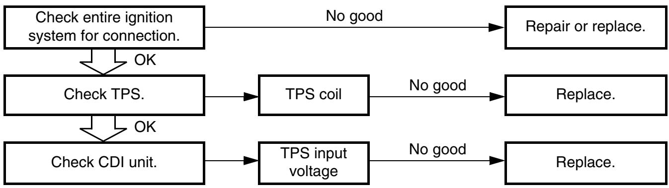
flowchart
graph TD
    A["Check entire ignition system for connection."] -->|OK| B["Check TPS."]
    B --> C["TPS coil"]
    C -->|No good| D["Replace."]
    B -->|OK| E["Check CDI unit."]
    E --> F["TPS input voltage"]
    F -->|No good| G["Replace."]
    A -->|No good| H["Repair or replace."]
NOTE:
Use the following special tools in this inspection.
Pocket tester:
YU-3112-C/90890-03112
SYSTEME TPS (CAPTEUR DE POSITION DE PAPILLON DES GAZ)
ETAPES DU CONTROLE
HANDLING NOTE
CAUTION:
Do not loosen the screw {TPS (throttle position sensor)} ① except when changing the TPS (throttle position sensor) due to failure because it will cause a drop in engine performance.
EC624000
COUPLERS AND LEADS CONNECTION INSPECTION
1. Check:
- Couplers and leads connection Rust/dust/looseness/short-circuit → Repair or replace.
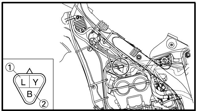
TPS COIL INSPECTION
1. Inspect:
- TPS coil resistance
Out of specification → Replace.
| Tester (+) lead → Blue lead 1 |
| Tester (−) lead → Black lead 2 |
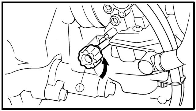
| TPS coil resistance | Tester selector position |
| 4 ~ 6 kΩ at 20 °C (68 °F) | kΩ × 1 |
2. Loosen:
- Throttle stop screw ①
NOTE:
Turn out the throttle stop screw until the throttle shaft is in the full close position.
SYSTEME TPS (CAPTEUR DE POSITION DE PAPILLON DES GAZ)
DROSSELKLAPPENSENSOR
3. Inspect:
- TPS coil variable resistance
Check that the resistance in increased as the throttle grip is moved from the full close position to the full open position.
Out of specification → Replace.
| Tester (+) lead → Yellow lead 1 |
| Tester (−) lead → Black lead 2 |
| TPS coil variable resistance | Tester selec-tor position |
| Full closed | Full opened | kΩ × 1 |
| 0 ~ 2 kΩ at 20 °C (68 °F) | 4 ~ 6 kΩ at 20 °C (68 °F) |
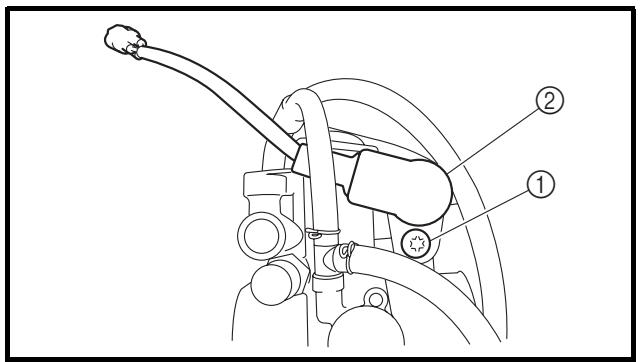
TPS REPLACEMENT AND ADJUSTMENT
1. Remove:
2. Remove:
NOTE:
Loosen the screw (TPS) using the T25 bit.
3. Replace:
- TPS
4. Install:
NOTE:
- Align the slot ⓐ in the TPS with the projection ⓑ on the carburetor.
- Temporarily tighten the screw (TPS).
5. Install:
SYSTEME TPS (CAPTEUR DE POSITION DE PAPILLON DES GAZ)
DROSSELKLAPPENSENSOR
Refer to "IDLE SPEED ADJUSTMENT" section in the CHAPTER 3.
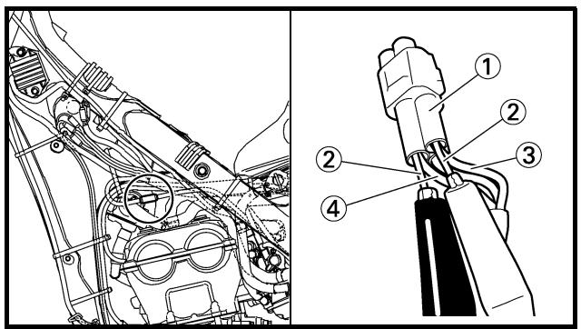
- Insert the thin electric conductors ② (lead) into the TPS coupler ①, as shown, and connect the tester to them.
Tester (+) lead → Yellow lead ③
Tester (−) lead → Black lead ④
CAUTION:
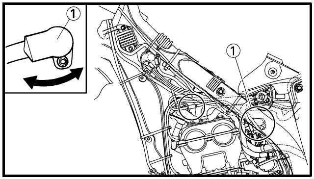
9. Adjust:
- TPS output voltage
Adjustment steps:
Adjust the installation angle of the TPS ① to obtain the specified output voltage.
NOTE:
Measure the output voltage accurately with a digital electronic voltmeter that gives an easy reading of a small voltage.
 | TPS output voltage | Tester selector position |
| 0.58 ~ 0.78 V | DCV |
SYSTEME TPS (CAPTEUR DE POSITION DE PAPILLON DES GAZ)
DROSSELKLAPPENSENSOR
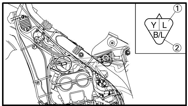
- Put the aligning marks ⓐ on the TPS and carburetor.
- Stop the engine.
-
Remove the carburetor.
-
Tighten:
- Screw (TPS) ①
NOTE:
Tighten the screw (TPS) using the T25 bit.
- Install the carburetor.
EC694000
- Disconnect the TPS coupler.
- Start the engine.
- Inspect:
- TPS input voltage
Out of specification → Replace the CDI unit.
| Tester (+) lead → Blue lead 1 |
| Tester (−) lead → Black/Blue lead 2 |
| TPS input voltage | Tester selector position |
| 4 ~ 6 V | DCV-20 |
| TPS input voltage | Tester selector position |
| 4 ~ 6 V | DCV-20 |
Refer to the following flow chart when inspecting the lighting system for possible problems.
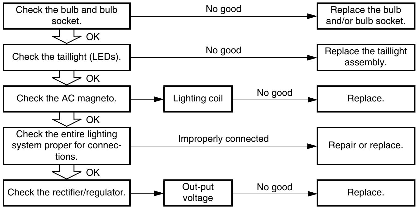
flowchart
graph TD
    A["Check the bulb and bulb socket."] -->|OK| B["Check the taillight (LEDs)."]
    B -->|OK| C["Check the AC magneto."]
    C -->|OK| D["Check the entire lighting system proper for connections."]
    D -->|OK| E["Check the rectifier/regulator."]
    A -->|No good| F["Replace the bulb and/or bulb socket."]
    B -->|No good| G["Replace the taillight assembly."]
    C --> H["Lighting coil"]
    D --> I["Improperly connected"]
    E --> J["Out-put voltage"]
    H --> K["Repair or replace."]
    J --> L["Replace."]
    H --> M["Improperly connected"]
NOTE:
- Remove the following parts before inspection.
1) Seat
2) Fuel tank
3) Left side cover
- Use the following special tool in this inspection.
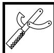
Pocket tester:
YU-3112-C/90890-03112
ECLAIRAGE
ETAPES DU CONTROLE
- Disconnect the taillight coupler.
- Connect two jumper leads ① from the battery terminals to the respective coupler terminal as shown.
Battery (+) terminal →
Blue lead ②
Battery (−) terminal →
Black lead ③
3. Check:
• LED (for proper operation)
Does not light → Replace the taillight assembly.
WARNING
- A wire that is used as a jumper lead must have at least the same capacity of the battery lead, otherwise the jumper lead may burn.
- This check is likely to produce sparks, therefore, make sure no flammable gas or fluid is in the vicinity.
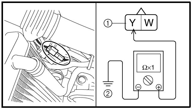
AC MAGNETO INSPECTION
1. Inspect:
- Lighting coil resistance
Out of specification → Replace.
| Tester (+) lead → Yellow lead 1 |
| Tester (−) lead → Ground 2 |
| Lighting coil resistance | Tester selector position |
| 0.224 ~ 0.336 Ω at 20 °C (68 °F) | Ω × 1 |
CONTROLE DU FEU ARRIERE (DEL)
RECTIFIER/REGULATOR INSPECTION
- Connect the battery leads.
- Start the engine.
-
Turn on the headlight and taillight by turning on the lights switch.
-
Inspect:
- Out-put voltage
Out of specification → Replace rectifier/regulator.
| Tester (+) lead → Yellow lead 1 |
| Tester (−) lead → Black lead 2 |
 | Out-put voltage | Tester selector position |
| 12.5 ~ 13.5 V at 5,000 r/min | ACV-20 |
CONTROLE DU REDRESSEUR/ REGULATEUR
If the speedometer will not operate, use the following inspection steps.
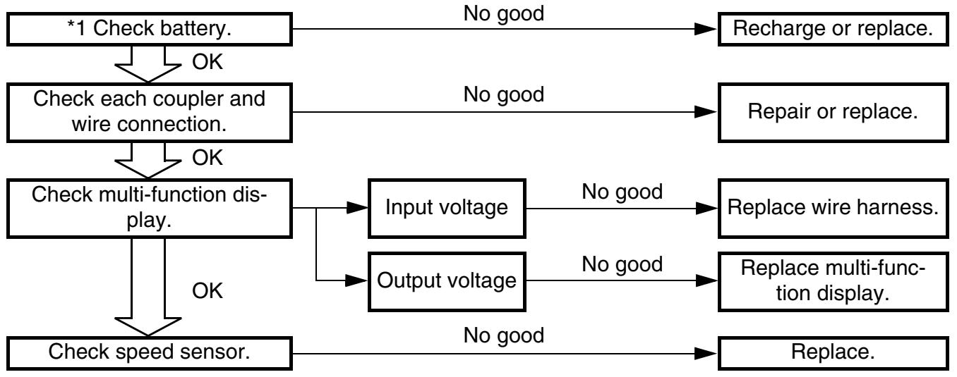
flowchart
graph TD
    A["*1 Check battery."] -->|OK| B["Check each coupler and wire connection."]
    B -->|OK| C["Check multi-function display."]
    C -->|OK| D["Check speed sensor."]
    A -->|No good| E["Recharge or replace."]
    B -->|No good| F["Repair or replace."]
    C --> G["Input voltage"]
    C --> H["Output voltage"]
    G -->|No good| I["Replace wire harness."]
    H -->|No good| J["Replace multi-function display."]
    D -->|No good| K["Replace."]
*1 marked: Refer to “BATTERY INSPECTION AND CHARGING” section in the CHAPTER 3.
NOTE:
- Remove the following parts before inspection.
1) Headlight
- Use the following special tools in this inspection.
Pocket tester:
YU-3112-C/90890-03112
SYSTEME DE SIGNALISATION
PROCEDURE DE CONTROLE
- Couplers and leads connection Rust/dust/looseness/short-circuit → Repair or replace.
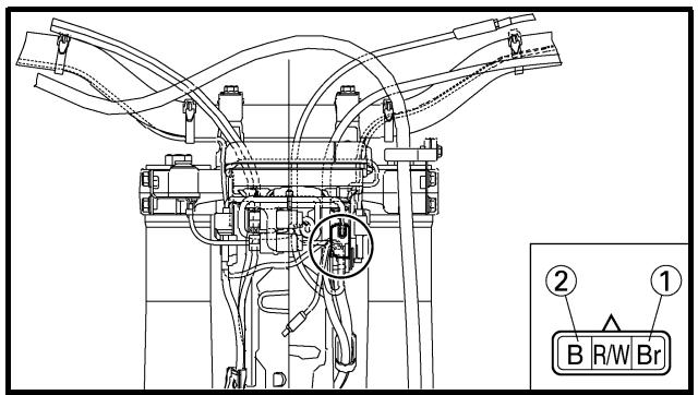
- Disconnect the multi-function display coupler.
- Set the main switch to "ON".
- Measure:
- Multi-function display input voltage
Out of specification → Replace wire harness.
Tester (+) lead → Brown lead ①
Tester (−) lead → Black lead ②
| Multi-function display input voltage | Tester selector position |
| 10 V or more | DCV-20 |
CAUTION:
Make sure that a short-circuit does not develop between the terminals because it may cause damage to electrical components.
MULTI-FUNCTION DISPLAY OUTPUT VOLTAGE INSPECTION
- Disconnect the multi-function display coupler.
- Set the main switch to "ON".
CONTROLE DES CONNEXIONS DES FICHES RAPIDES ET DES FILS
- Contrôler:
3. Measure:
- Multi-function display output voltage
Out of specification → Replace multi-function display.
Tester (+) lead → Red lead ①
Tester (−) lead → Black/White lead ②
| Multi-function display output voltage | Tester selector position |
| 4.5 V or more | DCV-20 |
CAUTION:
Make sure that a short-circuit does not develop between the terminals because it may cause damage to electrical components.
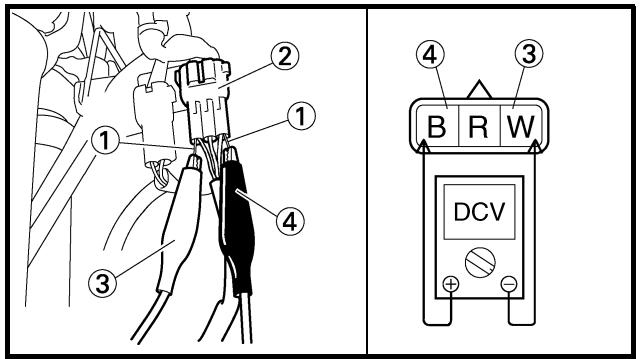
SPEED SENSOR OUTPUT VOLTAGE INSPECTION
- Insert the thin electric conductors ① (lead) into the speed sensor coupler ②, as shown, and connect the tester to them.
Tester (+) lead → White lead ③
Tester (−) lead → Black lead ④
CAUTION:
- Speed sensor output voltage
Output voltage not correct → Replace the speed sensor.
Measurement steps:
- Elevate the front wheel and slowly rotate it.
- Measure the voltage (DCV) of white lead and black lead. With each full rotation of the front wheel, the voltage reading should cycle from 0.6 V to 4.8 V to 0.6 V to 4.8 V.
3. Mesurer:
- The air/fuel mixture will vary depending on atmospheric conditions. Therefore, it is necessary to take into consideration the air pressure, ambient temperature, humidity, etc., when adjusting the carburetor.
- Perform a test run to check for proper engine performance (e.g., throttle response) and spark plug(-s) discoloration or fouling. Use these readings to determine the best possible carburetor setting.
NOTE:
It is recommended to keep a record of all carburetor settings and external conditions (e.g., atmospheric conditions, track/surface conditions, lap times) to make future carburetor setting easier.

WARNING
- The carburetor is a part of the fuel line. Therefore, be sure to install it in a well-ventilated area, away from flammable objects and any sources of fire.
- Never look into the carburetor intake. Flames may shoot out from the pipe if the engine backfires while it is being started. Gasoline may be discharged from the accelerator pump nozzle when the carburetor has been removed.
MISE AU POINT MOTEUR
- The carburetor is extremely sensitive to foreign matter (dirt, sand, water, etc.). During installation, do not allow foreign matter to get into the carburetor.
- Always handle the carburetor and its components carefully. Even slight scratches, bends or damage to carburetor parts may prevent the carburetor from functioning correctly. Carefully perform all servicing with the appropriate tools and without applying excessive force.
- When the engine is stopped or when riding at no load, do not open and close the throttle unnecessarily. Otherwise, too much fuel may be discharged, starting may become difficult or the engine may not run well.
- After installing the carburetor, check that the throttle operates correctly and opens and closes smoothly.
Atmospheric conditions and carburetor settings
| Air temp. | Humidity | Air pressure (altitude) | Mixture | Setting |
| High | High | Low (high) | Richer | Leaner |
| Low | Low | High (low) | Leaner | Richer |
The air density (i.e., concentration of oxygen in the air) determines the richness or leanness of the air/fuel mixture. Therefore, refer to the above table for mixture settings.
That is:
- Higher temperature expands the air with its resultant reduced density.
- Higher humidity reduces the amount of oxygen in the air by so much of the water vapor in the same air.
- Lower atmospheric pressure (at a high altitude) reduces the density of the air.
ATTENTION:
Effects of the setting parts on the throttle valve opening
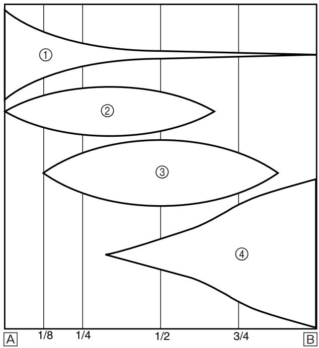
① Pilot jet
② Throttle valve cutaway
③ Jet needle
④ Main jet
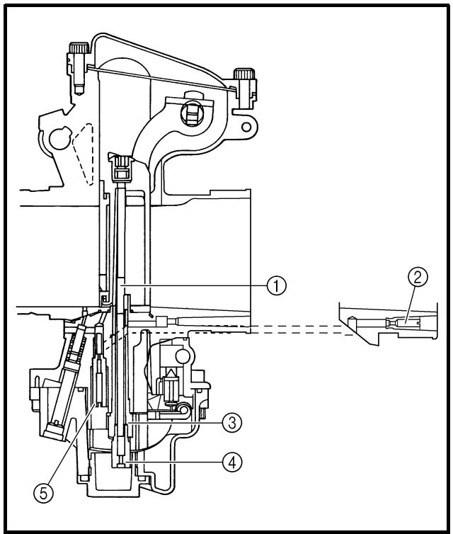
Main system
The FLATCR carburetor has a primary main jet. This type of main jet is perfect for racing machines since it supplies an even flow of fuel, even at full load. Use the main jet and the jet needle to set the carburetor.
① Jet needle
② Pilot air jet
③ Needle jet
④ Main jet
⑤ Pilot jet
natural_image
Technical line drawing of a mechanical assembly with labeled component (1), no readable text or symbols present.
Main jet adjustment
The richness of the air-fuel mixture at full throttle can be set by changing the main jet ①.
If the air-fuel mixture is too rich or too lean, the engine power will drop, resulting in poor acceleration.
Effects of changing the main jet (reference)
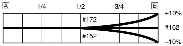
line
| X-axis | Line Value | Label |
|---|---|---|
| 1/4 | | |
| 1/2 | | #172 |
| 3/4 | | |
| B | +10% | #162 |
| B | -10% | |
A Idle
B Fully open
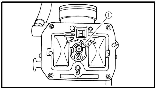
Pilot jet adjustment
The richness of the air-fuel mixture with the throttle open 1/4 or less can be set by adjusting the pilot jet ①.
Effects of adjusting the pilot jet (reference)
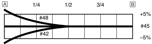
line
| X-axis | Line Color | Label |
|---|---|---|
| 1/4 | Black | #48 |
| 1/2 | Black | #45 |
| 3/4 | Black | #42 |
| +5% | Black | |
| -5% | Black | |
A Idle
B Fully open
line
| Label | Value |
|---|---|
| A | N*48 |
| B | N*45 |
| +5% | N*42 |
line
| X-Axis | Y-Axis Label |
|---|---|
| 1/4 | N°48 |
| 1/2 | N°45 |
| 3/4 | N°42 |
+5%
Jet needle groove position adjustment
NOTE:
For setting adjustment, replace the standard jet needle with the one designed for setting.
Adjusting the jet needle ① position affects the acceleration when the throttle is 1/8 to 3/4 open.
- Too rich at intermediate speeds
Rough engine operation is felt and the engine will not pick up speed smoothly. In this case, step up the jet needle clip by one groove and move down the needle to lean out the mixture.
- Too lean at intermediate speeds
The engine breathes hard and will not pick up speed quickly.
Step down the jet needle clip by one groove and move up the needle to enrich the mixture.
Effects of changing the jet needle groove position (reference)
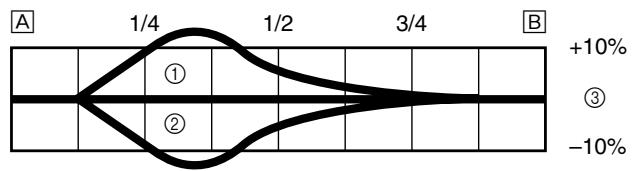
line
| Point | Value |
|-------|-------|
| ① | 1/4 |
| ② | 1/2 |
| 3/4 | 3/4 |
A Idle
B Fully open
① No.5 groove
② No.3 groove
③ No.4 groove
Jet needle adjustment
The jet needle is adjusted by changing it.
| Supplied jet needle | GDDUQ*GDDSQ |
* For CDN, AUS, NZ and ZA
The tapered sections of all jet needles have the same starting positions, but the needles are available with different straight-portion diameters.
GDDUQ - 4

line
| Point | Value |
|-------|-------|
| ① | 1/4 |
| ② | 1/2 |
| 3/4 | 3/4 |
line
| Point | Value |
|-------|-------|
| ① | 1/4 |
| ② | 1/2 |
| ③ | 3/4 |
| +10% | 10% |
| -10% | 0% |
Effects of changing the jet needle (reference)
(Diameter of the straight portion)
Changing the diameter of the straight portion adjusts the air-fuel mixture when the throttle is 1/8 to 1/4 open.
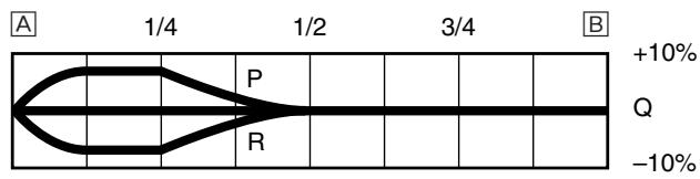
line
| Position | Value |
|--------|-------|
| P | +10% |
| R | -10% |
A Idle
B Fully open
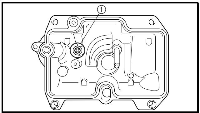
Leak jet adjustment (accelerator pump adjustment)
The leak jet ① is a setting part that adjusts the flow of fuel discharged by the accelerator pump. Since the accelerator pump operates only when throttle is open, the leak jet is used to adjust a fuel mixture ratio for quick throttle opening and is therefore different from other setting parts that adjust a fuel mixture for each throttle opening (each engine speed).
- The engine breathes hard in quick throttle opening.
Select a leak jet having lower calibrating No. than standard to enrich the mixture.
#60 → #55
- Rough engine operation is felt in quick throttle opening.
Select a leak jet having higher calibrating No. than standard to lean out the mixture.
#60 → #65
line
| Point | Value |
|-------|-------|
| P | 1/4 |
| R | 1/2 |
| Q | 3/4 |
| +10% | 3/4 |
| -10% | 3/4 |
line
| Point | Value |
|-------|-------|
| P | 1/4 |
| R | 1/2 |
| Q | 3/4 |
| +10% | 3/4 |
| -10% | 3/4 |
line
| Point | Value |
|---|---|
| P | +10% |
| Q | -10% |
Relationship with throttle opening
The flow of the fuel through the carburetor main system is controlled by the main jet and then, it is further regulated by the area between the main nozzle and the jet needle.
The fuel flow relates to the diameter of the straight portion of the jet needle with the throttle 1/8 to 1/4 open and relates to the clip position with the throttle 1/8 to 3/4 open.
Therefore, the fuel flow is balanced at each stage of throttle opening by the combination of the jet needle straight portion diameter, and clip position.
Carburetor setting parts
Examples of carburetor setting depending on symptom
| Symptom | Setting | Checking |
| At full throttleHard breathingShearing noiseWhitish spark plug↓Lean mixture | Increase main jet calibration no.(Gradually) | Discoloration of spark plug →If tan color, it is in good condition.If cannot be corrected:Clogged float valve seatClogged fuel hoseClogged fuel cockCheck that the accelerator pump operates smoothly. |
| At full throttleSpeed pick-up stopsSlow speed pick-upSlow responseSooty spark plug↓Rich mixture | Decrease main jet calibration no.(Gradually) | Discoloration of spark plug →If tan color, it is in good condition.If cannot be corrected:Clogged air cleanerFuel overflow from carburetor |
| Lean mixture | Lower jet needle clip position.(1 groove down) | 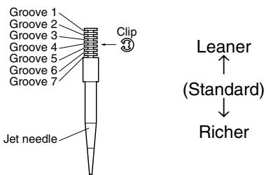 The clip position is the jet needle groove on which the clip is installed.The positions are numbered from the top.Check that the accelerator pump operates smoothly (except for rich mixture symptom). The clip position is the jet needle groove on which the clip is installed.The positions are numbered from the top.Check that the accelerator pump operates smoothly (except for rich mixture symptom). |
| Rich mixture | Raise jet needle clip position.(1 groove up) |
| 1/4 ~ 3/4 throttleHard breathingLack of speed | Lower jet needle clip position.(1 groove down) |
| 1/4 ~ 1/2 throttleSlow speed pick-upPoor acceleration | Raise jet needle clip position.(1 groove up) |
| Closed to 1/4 throttleHard breathingSpeed down | Use jet needle with a smaller diameter. | Slow-speed-circuit passageClogged → Clean.Overflow from carburetor |
| Closed to 1/4 throttlePoor acceleration | Use jet needle with a larger diameter.Raise jet needle clip position.(1 groove up) | |
| Poor response in the low to intermediate speeds | Raise jet needle clip position.If this has no effect, lower the jet needle clip position. | |
| Poor response when throttle is opened quickly | Check overall settings.Use main jet with a lower calibration no.Raise jet needle clip position.(1 groove up)If these have no effect, use a main jet with a higher calibration no. and lower the jet needle clip position. | Check air cleaner for fouling.Check that the accelerator pump operates smoothly. |
* This should be taken simply for an example. It is necessary to set the carburetor while checking the operating conditions of the engine.
Selection of the secondary reduction ratio (Sprocket)
Secondary reduction ratio = of driven sprocket teethNumber of drive sprocket teeth
| Standard secondary reduction ratio | 50/13 (3.846) |
- It is generally said that the secondary gear ratio should be reduced for a longer straight portion of a speed course and should be increased for a course with many corners. Actually, however, as the speed depends on the ground condition of the day of the race, be sure to run through the circuit to set the machine suitable for the entire course.
- In actuality, it is very difficult to achieve settings suitable for the entire course and some settings may be sacrificed. Thus, the settings should be matched to the portion of the course that has the greatest effect on the race result. In such a case, run through the entire course while making notes of lap times to find the best balance; then, determine the secondary reduction ratio.
- If a course has a long straight portion where a machine can run at maximum speed, the machine is generally set such that it can develop its maximum revolutions toward the end of the straight line, with care taken to avoid the engine over-revving.
NOTE:
Riding technique varies from rider to rider and the performance of a machine also vary from machine to machine. Therefore, do not imitate other rider's settings from the beginning but choose your own setting according to the level of your riding technique.
CHASSIS
EC72N000
Drive and driven sprockets setting parts
| Part name | Size | Part number |
| Drive sprocket 1(STD) | 13T | 5TJ-17460-00 |
| *(STD) | *13T | 9383E-13233 |
| **14T | 9383E-14215 |
* For CDN, EUROPE, AUS, NZ and ZA
** For AUS and NZ
| Part name | Size | Part number |
| Driven sprocket 2 | 48T | 5GS-25448-50 |
| *48T | 1C3-25448-00 |
| *49T | 1C3-25449-00 |
| (STD) | 50T | 5TJ-25450-80 |
| *(STD) | *50T | 1C3-25450-00 |
| *51T | 1C3-25451-00 |
| 52T | 5TJ-25452-80 |
| *52T | 1C3-25452-00 |
* For AUS and NZ
EC721002
Tire pressure
Tire pressure should be adjust to suit the road surface condition of the circuit.

Standard tire pressure: 100 kPa (1.0 kgf/cm ^2 , 15 psi)
- Under a rainy, muddy, sandy, or slippery condition, the tire pressure should be lower for a larger area of contact with the road surface.

Extent of adjustment:
60 \~ 80 kPa
(0.6 \~ 0.8 kgf/cm², 9.0 \~ 12 psi)
- Under a stony or hard road condition, the tire pressure should be higher to prevent a flat tire.

Extent of adjustment:
100 \~ 120 kPa
(1.0 \~ 1.2 kgf/cm², 15 \~ 18 psi)
The front fork setting should be made depending on the rider's feeling of an actual run and the circuit conditions.
The front fork setting includes the following three factors:
- Setting of air spring characteristics
- Change the fork oil level.
-
Setting of spring preload
-
Change the spring.
• Install the adjustment washer.
-
Setting of damping force
-
Change the compression damping.
- Change the rebound damping.
The spring acts on the load and the damping force acts on the cushion travel speed.
EC723001
Change in level and characteristics of fork oil
Damping characteristic near the final stroke can be changed by changing the fork oil amount.
CAUTION:
Adjust the oil level in 5 mm (0.2 in) increments or decrements. Too low oil level causes the front fork to produce a noise at full rebound or the rider to feel some pressure on his hands or body. Alternatively, too high oil level will develop unexpectedly early oil lock with the consequent shorter front fork travel and deteriorated performance and characteristics. Therefore, adjust the front fork within the specified range.

Standard oil level:
132 mm (5.20 in)
* 125 mm (4.92 in)
Extent of adjustment:
95 \~ 150 mm (3.74 \~ 5.91 in)
From top of outer tube with inner tube and damper rod fully compressed without spring.
* Except for USA and CDN
A Air spring characteristics in relation to oil level change
B Load
C Stroke
① Max. oil level
② Standard oil level
③ Min. oil level
EC727020
Spring preload adjustment
The spring preload is adjusted by installing the adjustment washer ① between the fork spring ② and damper rod ③.
CAUTION:
Do not install three or more adjustment washers for each front fork.
WARNING
Always adjust each front fork to the same setting. Uneven adjustment can cause poor handling and loss of stability.

Standard washer quantity:
Zero adjustment washers
Extent of adjustment:
Zero \~ 2 adjustment washers
A Load
B Fork stroke
① Without adjustment washer (standard)
② 1 adjustment washer
③ 2 adjustment washers
Setting of spring after replacement
As the front fork setting can be easily affected by rear suspension, take care so that the machine front and rear are balanced (in position, etc.) when setting the front fork.
1. Use of soft spring
Generally a soft spring gives a soft riding feeling. Rebound damping tends to become stronger and the front fork may sink deeply over a series of gaps.
To set a soft spring:
- Change the rebound damping.
Turn out one or two clicks.
- Change the compression damping.
Turn in one or two clicks.
2. Use of stiff spring
Generally a stiff spring gives a stiff riding feeling. Rebound damping tends to become weaker, resulting in lack of a sense of contact with the road surface or in a vibrating handlebar.
To set a stiff spring:
- Change the rebound damping.
Turn in one or two clicks.
- Change the compression damping.
Turn out one or two clicks.
EC72P000
Front fork setting parts
- Adjustment washer ①
| TYPE (thickness) | PART NUMBER |
| T = 2.3 mm (0.09 in) | 5XE-23364-00 |
- Front fork spring ②
| TYPE | SPRING RATE | SPRING PART NUMBER | I.D. MARK (slits) |
| SOFT | 0.408 | 5TJ-23141-00 | I |
| 0.418 | 5TJ-23141-10 | II |
| 0.428 | 5TJ-23141-20 | III |
| 0.438 | 5TJ-23141-30 | III |
| 0.449 | 5TJ-23141-40 | III |
| STD | 0.459 | 5TJ-23141-L0 | - |
| STIFF | 0.469 | 5TJ-23141-60 | I-II |
NOTE:
The I.D. mark (slits) ⓐ is proved on the end of the spring.
CAUTION:
When using a spring with a spring rate of 0.469 kg/mm, do not install two or more adjustment washers for each front fork.
Rear suspension setting
The rear suspension setting should be made depending on the rider's feeling of an actual run and the circuit conditions.
The rear suspension setting includes the following two factors:
-
Setting of spring preload
-
Change the set length of the spring.
-
Change the spring.
-
Setting of damping force
-
Change the rebound damping.
- Change the compression damping.
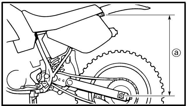
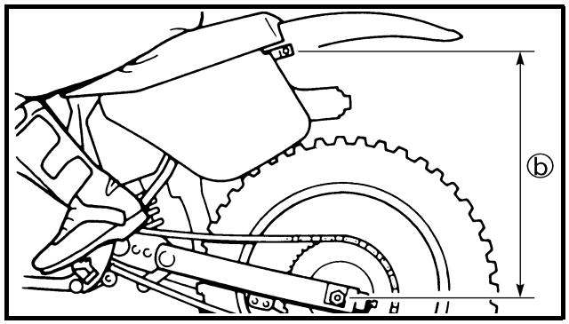
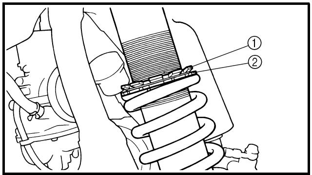
EC72C001
Choosing set length
- Place a stand or block under the engine to put the rear wheel above the floor, and measure the length ⓐ between the rear wheel axle center and the rear fender holding bolt.
- Remove the stand or block from the engine and with a rider astride the seat, measure the sunken length ⓑ between the rear wheel axle center and the rear fender holding bolt.
- Loosen the locknut ① and make adjustment by turning the spring adjuster ② to achieve the standard figure from the subtraction of the length ⑥ from the length ⑧.

Standard figure:
90 \~ 100 mm (3.5 \~ 3.9 in)
- If the machine is new and after it is broken in, the same set length of the spring may change because of the initial fatigue, etc. of the spring. Therefore, be sure to make re-evaluation.
- If the standard figure cannot be achieved by adjusting the spring adjuster and changing the spring set length, replace the spring with an optional one and make re-adjustment.
EC72G001
Setting of spring after replacement
After replacement, be sure to adjust the spring to the set length [sunken length 90 \~ 100 mm (3.5 \~ 3.9 in)] and set it.
- Use of soft spring
- Set the soft spring for less rebound damping to compensate for its less spring load. Run with the rebound damping adjuster one or two clicks on the softer side and readjust it to suit your preference.
- Use of stiff spring
- Set the soft spring for more rebound damping to compensate for its greater spring load. Run with the rebound damping adjuster one or two clicks on the stiffer side and readjust it to suit your preference.
* Adjusting the rebound damping will be followed more or less by a change in the compression damping. For correction, turn the low compression damping adjuster on the softer side.
N.B.:
natural_image
Technical line drawing of a mechanical spring assembly with dimension lines (no text or symbols)
CAUTION:
When using a rear cushion other than currently installed, use the one whose overall length ⓐ does not exceed the standard as it may result in faulty performance. Never use one whose overall length is greater than standard.

Length ⓐ of standard shock: 488.5 mm (19.23 in)
ATTENTION:
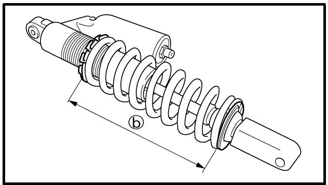
natural_image
Technical line drawing of a mechanical spring assembly with dimension label (b), no text or symbols present
EC72Q000
Rear shock absorber setting parts
- Rear shock spring ①
| TYPE | SPRING RATE | SPRING PART NUMBER | I.D. COLOR/ POINT | SPRING FREE LENGTH |
| SOFT | 4.3 | 5UN-22212-00 | Brown/1 | 260 |
| 4.5 | 5UN-22212-10 | Green/1 | 260 |
| 4.7 | 5UN-22212-20 | Red/1 | 260 |
| 4.9 | 5UN-22212-30 | Black/1 | 260 |
| 5.1 | 5UN-22212-40 | Blue/1 | 260 |
| 5.3 | 5UN-22212-50 | Yellow/1 | 260 |
| STD | 5.5 | 5UN-22212-60 | Pink/1 | 260 |
| STIFF | 5.7 | 5UN-22212-70 | White/1 | 260 |
NOTE: The I.D. color ⓐ is marked at the end of the spring.
- Extent of adjustment (spring length)
| SPRING FREE LENGTH | EXTENT OF ADJUSTMENT 6 |
| 260 mm (10.24 in) | 238.5 ~ 258.5 mm(9.39 ~ 10.18 in) |
- If any of the following symptoms is experienced with the standard position as the base, make resetting by reference to the adjustment procedure given in the same chart.
- Before any change, set the rear shock absorber sunken length to the standard figure 90 \~ 100 mm (3.5 \~ 3.9 in).
| Symptom | Section | Check | Adjust |
| Jump | Large gap | Medium gap | Small gap |
| Stiff over entire range | ○ | ○ | ○ | | Compression dampingOil level (oil amount)Spring | Turn adjuster counterclockwise (about 2 clicks) to decrease damping.Decrease oil level by about 5 ~ 10 mm (0.2 ~ 0.4 in).Replace with soft spring. |
| Unsmooth movement over entire range | ○ | ○ | ○ | ○ | Outer tubeInner tubeUnder bracket tightening torque | Check for any bends, dents, and other noticeable scars, etc. If any, replace affected parts.Retighten to specified torque. |
| Poor initial movement | | | | ○ | Rebound dampingOil seal | Turn adjuster counterclockwise (about 2 clicks) to decrease damping.Apply grease in oil seal wall. |
| Soft over entire range, bottoming out | ○ | ○ | | | Compression dampingOil level (oil amount)Spring | Turn adjuster clockwise (about 2 clicks) to increase damping.Increase oil level by about 5 ~ 10 mm (0.2 ~ 0.4 in).Replace with stiff spring. |
| Stiff toward stroke end | ○ | | | | Oil level (oil amount) | Decrease oil level by about 5 mm (0.2 in). |
| Soft toward stroke end, bottoming out | ○ | | | | Oil level (oil amount) | Increase oil level by about 5 mm (0.2 in). |
| Stiff initial movement | ○ | ○ | ○ | ○ | Compression damping | Turn adjuster counterclockwise (about 2 clicks) to decrease damping. |
| Low front, tending to lower front posture | | | ○ | ○ | Compression dampingRebound dampingBalance with rear endOil level (oil amount) | Turn adjuster clockwise (about 2 clicks) to increase damping.Turn adjuster counterclockwise (about 2 clicks) to decrease damping.Set sunken length for 95 ~ 100 mm (3.7 ~ 3.9 in) when one passenger is astride seat (lower rear pos-ture).Increase oil level by about 5 mm (0.2 in). |
| “Obtrusive” front, tending to upper front posture | | | ○ | ○ | Compression dampingBalance with rear endSpringOil lever (oil amount) | Turn adjuster counterclockwise (about 2 clicks) to decrease damping.Set sunken length for 90 ~ 95 mm (3.5 ~ 3.7 in) when one passenger is astride seat (upper rear pos-ture).Replace with soft spring.Decrease oil level by about 5 ~ 10 mm (0.2 ~ 0.4 in). |
- Rear shock absorber
NOTE:
- If any of the following symptoms is experienced with the standard position as the base, make resetting by reference to the adjustment procedure given in the same chart.
- Adjust the rebound damping in 2-click increments or decrements.
- Adjust the low compression damping in 1-click increments or decrements.
- Adjust the high compression damping in 1/6 turn increments or decrements.
| Symptom | Section | Check | Adjust |
| Jump | Large gap | Medium gap | Small gap |
| Stiff, tending to sink | | | ○ | ○ | Rebound dampingSpring set length | Turn adjuster counterclockwise (about 2 clicks) to decrease damping.Set sunken length for 90 ~ 100 mm (3.5 ~ 3.9 in) when one passenger is astride seat. |
| Spongy and unstable | | | ○ | ○ | Rebound dampingLow compression dampingSpring | Turn adjuster clockwise (about 2 clicks) to increase damping.Turn adjuster clockwise (about 1 click) to increase damping.Replace with stiff spring. |
| Heavy and dragging | | | ○ | ○ | Rebound dampingSpring | Turn adjuster counterclockwise (about 2 clicks) to decrease damping.Replace with soft spring. |
| Poor road gripping | | | | ○ | Rebound dampingLow compression dampingHigh compression dampingSpring set lengthSpring | Turn adjuster counterclockwise (about 2 clicks) to decrease damping.Turn adjuster clockwise (about 1 clicks) to increase damping.Turn adjuster clockwise (about 1/6 clicks) to increase damping.Set sunken length for 90 ~ 100 mm (3.5 ~ 3.9 in) when one passenger is astride seat.Replace with soft spring. |
| Bottoming out | ○ | ○ | | | High compression dampingSpring set lengthSpring | Turn adjuster clockwise (about 1/6 turn) to increase damping.Set sunken length for 90 ~ 100 mm (3.5 ~ 3.9 in) when one passenger in astride seat.Replace with stiff spring. |
| Bouncing | ○ | ○ | | | Rebound dampingSpring | Turn adjuster clockwise (about 2 clicks) to increase damping.Replace with soft spring. |
| Stiff travel | ○ | ○ | | | High compression dampingSpring set lengthSpring | Turn adjuster counterclockwise (about 1/6 turn) to decrease damping.Set sunken length for 95 ~ 100 mm (3.7 ~ 3.9 in) when one passenger is astride seat.Replace with soft spring. |