WR250F-2007 - Off-road motorcycle YAMAHA - Free user manual and instructions
Find the device manual for free WR250F-2007 YAMAHA in PDF.
| Product type | Off-road motorcycle (competition) |
| Brand | YAMAHA |
| Model | WR250F-2007 |
| Dimensions (L × W × H) | 2165 × 825 × 1300 mm (USA) / 2180 × 825 × 1305 mm (Europe) |
| Seat height | 980 mm (USA) / 990 mm (Europe) |
| Dry weight | 106.0 kg |
| Engine | 4-stroke, liquid-cooled, 249 cm³, 12.5:1 |
| Starting | Kick and electric |
| Fuel | Premium unleaded gasoline 95 RON, tank 8.0 L |
| Transmission | 5-speed constant mesh, chain |
| Front suspension | Telescopic fork, travel 300 mm |
| Rear suspension | Monocross swingarm, travel 310 mm |
| Brakes | Front and rear disc brakes |
| Front/rear tires | 80/100-21 (USA) or 90/90-21 (Europe) / 100/100-18 (USA) or 130/90-18 (Europe) |
| Multifunction display | Speedometer, clock, odometers, stopwatch (race mode) |
| Battery | 12 V / 4 Ah, maintenance-free (MF) |
| Lighting | Halogen headlight 12V 35/36.5W, taillight 12V 1.6/0.3W |
| Maintenance | Engine oil change 1.1 L, wet air filter, carburetor adjustment |
| Safety | Cut-off switch, starting only in neutral or with clutch, mandatory protective equipment |
| Usage | Competition on closed circuit, prohibited on public roads |
Frequently Asked Questions - WR250F-2007 YAMAHA
User questions about WR250F-2007 YAMAHA
0 question about this device. Answer the ones you know or ask your own.
Ask a new question about this device
Download the instructions for your Off-road motorcycle in PDF format for free! Find your manual WR250F-2007 - YAMAHA and take your electronic device back in hand. On this page are published all the documents necessary for the use of your device. WR250F-2007 by YAMAHA.
USER MANUAL WR250F-2007 YAMAHA
OWNER'S SERVICE MANUAL
MANUEL D'ATELIER DU
PROPRIETAIRE
FAHRER- UND
WARTUNGSHANDBUCH
OWNER'S SERVICE MANUAL
©2006 by Yamaha Motor Co., Ltd.
1st Edition, August 2006
All rights reserved.
Any reprinting or unauthorized
use without the written
permission of
Yamaha Motor Co., Ltd.
is expressly prohibited.
Printed in Japan
WR250F(W)
MANUEL D'ATELIER
DU PROPRIETAIRE
©2006 Yamaha Motor Co., Ltd.
©2006 by Yamaha Motor Co., Ltd.
Congratulations on your purchase of a Yamaha WR series. This model is the culmination of Yamaha's vast experience in the production of pace-setting racing machines. It represents the highest grade of craftsmanship and reliability that have made Yamaha a leader.
This manual explains operation, inspection, basic maintenance and tuning of your machine. If you have any questions about this manual or your machine, please contact your Yamaha dealer.
NOTE:
Yamaha continually seeks advancements in product design and quality. Therefore, while this manual contains the most current product information available at the time of printing, there may be minor discrepancies between your machine and this manual. If you have any questions concerning this manual, please consult your Yamaha dealer.
WARNING
PLEASE READ THIS MANUAL CAREFULLY AND COMPLETELY BEFORE OPERATING THIS MACHINE. DO NOT ATTEMPT TO OPERATE THIS MACHINE UNTIL YOU HAVE ATTAINED A SATISFACTORY KNOWLEDGE OF ITS CONTROLS AND OPERATING FEATURES AND UNTIL YOU HAVE BEEN TRAINED IN SAFE AND PROPER RIDING TECHNIQUES. REGULAR INSPECTIONS AND CAREFUL MAINTENANCE, ALONG WITH GOOD RIDING SKILLS, WILL ENSURE THAT YOU SAFETY ENJOY THE CAPABILITIES AND THE RELIABILITY OF THIS MACHINE.
INTRODUCTION
THIS MACHINE IS DESIGNED STRICTLY FOR COMPETITION USE, ONLY ON A CLOSED COURSE. It is illegal for this machine to be operated on any public street, road, or highway. Off-road use on public lands may also be illegal. Please check local regulations before riding.
SAFETY INFORMATION
- THIS MACHINE IS TO BE OPERATED BY AN EXPERI-ENCED RIDER ONLY.
Do not attempt to operate this machine at maximum power until you are totally familiar with its characteristics.
-
THIS MACHINE IS DESIGNED TO BE RIDDEN BY THE OPERATOR ONLY. Do not carry passengers on this machine.
-
ALWAYS WEAR PROTEC-TIVE APPAREL.
When operating this machine, always wear an approved helmet with goggles or a face shield. Also wear heavy boots, gloves, and protective clothing. Always wear proper fitting clothing that will not be caught in any of the moving parts or controls of the machine.
- ALWAYS MAINTAIN YOUR MACHINE IN PROPER WORKING ORDER.
For safety and reliability, the machine must be properly maintained. Always perform the pre-operation checks indicated in this manual. Correcting a mechanical problem before you ride may prevent an accident.
- GASOLINE IS HIGHLY FLAMMABLE.
Always turn off the engine while refueling. Take care to not spill any gasoline on the engine or exhaust system. Never refuel in the vicinity of an open flame, or while smoking.
NOTICE
IMPORTANT
If you should swallow some gasoline, inhale excess gasoline vapors, or allow any gasoline to get into your eyes, contact a doctor immediately. If any gasoline spills onto your skin or clothing, immediately wash skin areas with soap and water, and change your clothes.
- ONLY OPERATE THE MACHINE IN AN AREA WITH ADEQUATE VENTILATION.
Never start the engine or let it run for any length of time in an enclosed area.
Exhaust fumes are poisonous. These fumes contain carbon monoxide, which by itself is odorless and colorless. Carbon monoxide is a dangerous gas which can cause unconsciousness or can be lethal.
- PARK THE MACHINE CAREFULLY; TURN OFF THE ENGINE.
Always turn off the engine if you are going to leave the machine. Do not park the machine on a slope or soft ground as it may fall over.
- THE ENGINE, EXHAUST PIPE, MUFFLER, AND OIL TANK WILL BE VERY HOT AFTER THE ENGINE HAS BEEN RUN.
Be careful not to touch them or to allow any clothing item to contact them during inspection or repair.
- PROPERLY SECURE THE MACHINE BEFORE TRANSPORTING IT.
When transporting the machine in another vehicle, always be sure it is properly secured and in an upright position and that the fuel cock is in the "OFF" position. Otherwise, fuel may leak out of the carburetor or fuel tank.
- L'ESSENCE PEUT CAUSER DES BLESSURES.
This manual will provide you with a good basic understanding of features, operation, and basic maintenance and inspection items of this machine. Please read this manual carefully and completely before operating your new machine. If you have any questions regarding the operation or maintenance of your machine, please consult your Yamaha dealer.
NOTE:
This manual should be considered a permanent part of this machine and should remain with it even if the machine is subsequently sold.
EC060000
NOTICE
Some data in this manual may become outdated due to improvements made to this model in the future. If there is any question you have regarding this manual or your machine, please consult your Yamaha dealer.
EC070001
F.I.M. MACHINE WEIGHTS:
Weights of machines without fuel
The minimum weights for motocross machines are:
for the class 125 cc .... minimum
88 kg (194 lb)
for the class 250 cc .... minimum
98 kg (216 lb)
for the class 500 cc .... minimum
102 kg (225 lb)
In modifying your machine (e.g., for weight reduction), take note of the above limits of weight.
AU NOUVEAU PROPRIETAIRE
HOW TO USE THIS MANUAL
EC081000
PARTICULARLY IMPORTANT INFORMATION

The Safety Alert Symbol means ATTENTION! BECOME ALERT! YOUR SAFETY IS INVOLVED!
WARNING
Failure to follow WARNING instructions could result in severe injury or death to the machine operator, a bystander, or a person inspecting or repairing the machine.
CAUTION:
A CAUTION indicates special precautions that must be taken to avoid damage to the machine.
NOTE:
A NOTE provides key information to make procedures easier or clearer.
COMMENT UTILISER CE MANUEL INFORMATIONS PARTICULIEREMENT IMPORTANTES

- This manual consists of seven chapters; "General information", "Specifications", "Regular inspection and adjustments", "Tuning", "Engine", "Chassis" and "Electrical".
- The table of contents is at the beginning of the manual. Look over the general layout of the book before finding then required chapter and item. Bend the book at its edge, as shown, to find the required fore edge symbol mark and go to a page for required item and description.
TROUVER LA PAGE RECHERCHEE
All of the procedures in this manual are organized in a sequential, step-by-step format. The information has been complied to provide the mechanic with an easy to read, handy reference that contains comprehensive explanations of all disassembly, repair, assembly, and inspection operations.
In this revised format, the condition of a faulty component will precede an arrow symbol and the course of action required will follow the symbol, e.g.,
- Bearings
Pitting/damage Replace.
EC084002
HOW TO READ DESCRIPTIONS
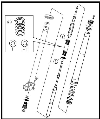
To help identify parts and clarify procedure steps, there are exploded diagrams at the start of each removal and disassembly section.
- An easy-to-see exploded diagram ① is provided for removal and disassembly jobs.
- Numbers ② are given in the order of the jobs in the exploded diagram. A number that is enclosed by a circle indicates a disassembly step.
- An explanation of jobs and notes is presented in an easy-to-read way by the use of symbol marks ③. The meanings of the symbol marks are given on the next page.
- A job instruction chart ④ accompanies the exploded diagram, providing the order of jobs, names of parts, notes in jobs, etc.
- Extent of removal ⑤ is provided in the job instruction chart to save the trouble of an unnecessary removal job.
- For jobs requiring more information, the step-by-step format supplements ⑥ are given in addition to the exploded diagram and job instruction chart.
FORMAT DU MANUEL
EC494020 INSPECTION
EC484100 Clutch housing and boss
1. Inspect:
- Clutch housing (1)
Cracks/wear/damage Replace.
- Clutch boss ②
Scoring/wear/damage Replace.
EC484201 Primai
1. Check:
Circumferential play
Free play exists Replace.
Gear teeth @
Wear/damage Replace.
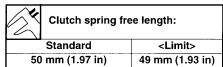
EC484000 Clutch spring
1.Measure:
- Clutch spring free length (a)
Out of specification Replace springs
as a set.
4-47
AUFBAU
ILLUSTRATED SYMBOLS (Refer to the illustration)
Illustrated symbols ① to ⑦ are designed as thumb tabs to indicate the chapter's number and content.
① General information
(2) Specifications
③ Regular inspection and adjustments
④ Tuning
⑤ Engine
(6) Chassis
⑦ Electrical
Illustrated symbols ⑧ to ⑭ are used to identify the specifications appearing in the text.
(8) With engine mounted
9 Special tool
10 Filling fluid
① Lubricant
12 Tightening
⑬ Specified value, Service limit
14 Resistance () Voltage (V), Electric current (A)
Illustrated symbols ⑤ to ⑧ in the exploded diagrams indicate grade of lubricant and location of lubrication point.
15 Apply engine oil
16 Apply molybdenum disulfide oil
⑦ Apply lightweight lithium-soap base grease
Apply molybdenum disulfide grease
Illustrated symbols 19 to 20 in the exploded diagrams indicate where to apply a locking agent and where to install new parts.
19 Apply locking agent (LOCTITE®)
Use new one
SYMBOLS
GRAPHIQUES
CHAPITRE 4 MISE AU POINT
ENGINE 4-1
CHASSIS 4-21
MOTEUR 4-1
CHÄSSIS 4-21
CHAPTER 5 ENGINE
CHAPITRE 5 MOTEUR
RADIATOR 5-1
CARBURETOR 5-9
AIR INDUCTION SYSTEM 5-39
CAMSHAFTS 5-45
CYLINDER HEAD 5-67
VALVES AND VALVE
SPRINGS 5-75
CYLINDER AND PISTON 5-95
CLUTCH 5-111
OIL FILTER ELEMENT, WATER PUMP AND RIGHT
CRANKCASE COVER 5-129
BALANCER. 5-145
OIL PUMP 5-153
OIL TANK 5-157
KICK SHAFT AND SHIFT
SHAFT 5-167
AC MAGNETO AND
STARTER CLUTCH 5-185
ENGINE REMOVAL 5-207
CRANKCASE AND CRANKSHAFT 5-221
TRANSMISSION,SHIFT CAM
AND SHIFT FORK 5-245
CHAPTER 6 CHASSIS
RADIATEUR 5-2
CARBURATEUR 5-10
SYSTEME D'INDUCTION
D'AIR 5-40
ARBRES A CAMES. 5-46
CULASSE 5-68
SOUPAPES ET RESSORTS
DE SOUPAPES. 5-76
CYLINDRE ET PISTON. 5-96
EMBRAYAGE. 5-112
ELEMENT DE FILTRE
A HUIL, POMPE A EAU
ET DEMI-CARTER DROIT.....5-130
BALANCIER 5-146
POMPE A HUILE 5-154
RÉSERVOIR D'HUILE 5-158
① Clutch lever
(2) Hot starter lever
③ Engine stop switch
④ Multi-function display
⑤ Main switch
⑥ Start switch
(7) Front brake lever
⑧ Throttle grip
9 Radiator cap
Fuel tank cap
① Taillight
⑫ Kickstarter crank
(13) Fuel tank
14 Headlight
15 Radiator
Coolant drain bolt
⑦ Rear brake pedal
18 Valve joint
19 Fuel cock
20 Cold starter knob
② Air cleaner
Catch tank
Drive chain
24 Oil level check window
Shift pedal
26 Front fork
NOTE:
- The machine you have purchased may differ slightly from those shown in the following.
- Designs and specifications are subject to change without notice.
RENSEIGNEMENTS GENERAUX DESCRIPTION
⑤ Interruptor principal
⑥ Interruptor de arranque
(7) Maneta de freno delantero
(8) Puno del accelerador
There are two significant reasons for knowing the serial number of your machine:
- When ordering parts, you can give the number to your Yamaha dealer for positive identification of the model you own.
- If your machine is stolen, the authorities will need the number to search for and identify your machine.
IDENTIFICATION DE LA MOTO
The vehicle identification number ① is stamped on the right of the steering head pipe.
NUMERO D'IDENTIFICATION DE LA MOTO
The engine serial number ① is stamped into the elevated part of the right-side of the engine.
NUMERO DE SERIE DU MOTEUR
The model label ① is affixed to the frame under the rider's seat. This information will be needed to order spare parts.
ETIQUETE DE MODELE
EC131010 PREPARATION FOR REMOVAL AND DISASSEMBLY
- Remove all dirt, mud, dust, and foreign material before removal and disassembly.
When washing the machine with high pressured water, cover the parts follows.
- Silencer exhaust port
- Side cover air intake port
Water pump housing hole at the bottom - Drain hole on the cylinder head
(right side)
-
All electrical components
-
Use proper tools and cleaning equipment. Refer to "SPECIAL TOOLS" section.
-
When disassembling the machine, keep mated parts together. They include gears, cylinders, pistons, and other mated parts that have been "mated" through normal wear. Mated parts must be reused as an assembly or replaced.
- During the machine disassembly, clean all parts and place them in trays in the order of disassembly. This will speed up assembly time and help assure that all parts are correctly reinstalled.
- Keep away from fire.
EC132000 ALL REPLACEMENT PARTS
- We recommend to use Yamaha genuine parts for all replacements. Use oil and/or grease recommended by Yamaha for assembly and adjustment.
INFORMATIONS IMPORTANTES
PREPARATION A LA DEPOSE ET AU DEMONTAGE
GASKETS, OIL SEALS AND O-RINGS
- All gaskets, oil seals, and O-rings should be replaced when an engine is overhauled. All gasket surfaces, oil seal lips, and O-rings must be cleaned.
- Properly oil all mating parts and bearings during reassembly. Apply grease to the oil seal lips.
JOINTS, BAGUES D'ETANCHEITE ET JOINTS TORIQUES
LOCK WASHERS/PLATES AND COTTER PINS
- All lock washers/plates ① and cotter pins must be replaced when they are removed. Lock tab(s) should be bent along the bolt or nut flat(s) after the bolt or nut has been properly tightened.
EC135001
BEARINGS AND OIL SEALS
- Install the bearing(s) ① and oil seal(s) ② with their manufacturer's marks or numbers facing outward. (In other words, the stamped letters must be on the side exposed to view.) When installing oil seal(s), apply a light coating of lightweight lithium base grease to the seal lip(s). Oil the bearings liberally when installing.
CAUTION:
Do not use compressed air to spin the bearings dry. This causes damage to the bearing surfaces.
RONDELLES-FREINS, FREINS D'ECROU ET GOUPILLES FENDUES
- All circlips should be inspected carefully before reassembly. Always replace piston pin clips after one use. Replace distorted circlips. When installing a circlip ① , make sure that the sharpened corner ② is positioned opposite to the thrust ③ it receives. See the sectional view.
④ Shaft
CIRCLIPS
CHECKING OF CONNECTION
Dealing with stains, rust, moisture, etc. on the connector.
-
Disconnect:
-
Connector
-
Dry each terminal with an air blower.
- Connect and disconnect the connector two or three times.
- Pull the lead to check that it will not come off.
-
If the terminal comes off, bend up the pin ① and reinsert the terminal into the connector.
-
Connect:
-
Connector
NOTE:
The two connectors "click" together.
- Check for continuity with a tester.
NOTE:
- If there is no continuity, clean the terminals.
- Be sure to perform the steps 1 to 7 listed above when checking the wire harness.
- For a field remedy, use a contact revitalizer available on the market.
- Use the tester on the connector as shown.
VERIFICATION DES CONNXIONS
The proper special tools are necessary for complete and accurate tune-up and assembly. Using the correct special tool will help prevent damage caused by the use of improper tools or improvised techniques. The shape and part number used for the special tool differ by country, so two types are provided. Refer to the list provided to avoid errors when placing an order.
NOTE:
- For U.S.A. and Canada, use part number starting with "YM-", "YU-" or "ACC-".
- For others, use part number starting with "90890".
| Part number | Tool name/How to use | Illustration | |
| YU-1135-A, 90890-01135 | Crankcase separating toolThese tool is used to remove the crankshaft from either case. | YU-1135-A | 90890-01135 |
| YU-3097, 90890-01252 YU-1256 | Dial gauge and stand StandThese tools are used to check each part for runout or bent. | YU-3097 YU-1256 | 90890-01252 |
| YU-90050, 90890-01274 YU-90050, 90890-01275 YM-91044, 90890-04081 YU-90063, 90890-01278 | Crankshaft installing tool Crankshaft installing pot Crankshaft installing bolt Spacer (crankshaft installer) Adapter (M12) These tools are used to install the crankshaft. | YU-90050 YU-90063 YM-91044 | 90890-01274 90890-01275 90890-01278 90890-04081 |
| YU-1304, 90890-01304 | Piston pin puller setThis tool is used to remove the piston pin. | YU-1304 | 90890-01304 |
| YU-24460-01, 90890-01325 YU-33984, 90890-01352 | Radiator cap tester Radiator cap tester adapterThese tools are used for checking the cooling system. | YU-24460-01 YU-33984 | 90890-01325 90890-01352 |
| YU-33975, 90890-01403 | Steering nut wrench This tool is used when tighten the steering ring nut to specification. | YU-33975 | 90890-01403 |
| YM-01494, 90890-01494 | Damper rod holder Use this tool to remove and install the damper rod. | YM-01494 | 90890-01494 |
| YM-A0948, 90890-01502 | Fork seal driver This tool is used when install the fork oil seal. | YM-A0948 | 90890-01502 |
| YS-1880-A, 90890-01701 | Sheave holderThis tool is used for when loosening or tightening the flywheel magneto securing nut. | YS-1880-A | 90890-01701 |
| YU-3112-C, 90890-03112 | Pocket testerUse this tool to inspect the coil resistance, output voltage and amperage. | YU-3112-C | 90890-03112 |
| YM-33277-A, 90890-03141 | Timing lightThis tool is necessary for checking ignition timing. | YM-33277-A | 90890-03141 |
| YM-4019, 90890-04019 | Valve spring compressorThis tool is needed to remove and install the valve assemblies. | YM-4019 | 90890-04019 |
| YM-91042, 90890-04086 | Clutch holding toolThis tool is used to hold the clutch when removing or installing the clutch boss securing nut. | YM-91042 | 90890-04086 |
| YM-4111, 90890-04111YM-4116, 90890-04116 | Valve guide removerIntake 4.0 mm (0.16 in)Exhaust 4.5 mm (0.18 in)This tool is needed to remove and install the valve guide. | YM-4111YM-4116 | 90890-0411190890-04116 |
| YM-4112, 90890-04112YM-4117, 90890-04117 | Valve guide installerIntake 4.0 mm (0.16 in)Exhaust 4.5 mm (0.18 in)This tool is needed to install the valve guide. | YM-4112YM-4117 | 90890-0411290890-04117 |
| YM-4113, 90890-04113YM-4118, 90890-04118 | Valve guide reamerIntake 4.0 mm (0.16 in)Exhaust 4.5 mm (0.18 in)This tool is needed to rebore the new valve guide. | YM-4113YM-4118 | 90890-0411390890-04118 |
| YM-04141, 90890-04141 | Rotor pullerThis tool is used to remove the flywheel magneto. | YM-04141 | 90890-04141 |
| YM-34487 90890-06754 | Dynamic spark tester Ignition checker This instrument is necessary for checking the ignition system components. | YM-34487 | 90890-06754 |
| YB-35956-A, 90890-06756 | Vacuum/pressure pump gauge set This tool is used to check the air induction system. | YB-35956-A | 90890-06756 |
| 90890-85505 | YAMAHA Bond No. 1215 (ThreeBond® No. 1215) This sealant (Bond) is used for crankcase mating surface, etc. | 90890-85505 | 90890-85505 |
OUTILS SPECIAUX
Functions of the respective switch positions are as follows:
ON:
The engine can be started only at this position.
OFF:
All electrical circuits are switched off.
Main switch indicator light
The main switch ① is equipped with an indicator light ② to avoid forgetting to turn it off. This light functions as follows.
It lights up with the main switch "ON".
- It goes out when the engine increases its speed after being started.
- It lights up again when the engine is stopped.
NOTE:
If the indicator light will not light up with the main switch "ON", it shows a lack of the battery voltage. Recharge the battery.
FUNCTIONS DES
COMMANDES
CONTACTEUR A CLE
The engine stop switch ① is located on the left handlebar. Continue pushing the engine stop switch till the engine comes to a stop.
COUPE-CIRCUIT DU MOTEUR
The start switch ① is located on the right handlebar. Push this switch to crank the engine with the starter.
CONTACTEUR DU DEMARREUR
The clutch lever ① is located on the left handlebar; it disengages or engages the clutch. Pull the clutch lever to the handlebar to disengage the clutch, and release the lever to engage the clutch. The lever should be pulled rapidly and released slowly for smooth starts.
LEVIER D'EMBRAYAGE
INTERRUPTORE DI ACCENSIONE
The gear ratios of the constant-mesh 5 speed transmission are ideally spaced. The gears can be shifted by using the shift pedal ① on the left side of the engine.
SELECTEUR
Rotate the kickstarter crank ① away from the engine. Push the starter down lightly with your foot until the gears engage, then kick smoothly and forcefully to start the engine. This model has a primary kickstarter crank so the engine can be started in any gear if the clutch is disengaged. In normal practices, however, shift to neutral before starting.
PEDALE DE KICK
The throttle grip ① is located on the right handlebar; it accelerates or decelerates the engine. For acceleration, turn the grip toward you; for deceleration, turn it away from you.
POIGNEE DES GAZ
The front brake lever ① is located on the right handlebar. Pull it toward the handlebar to activate the front brake.
LEVIER DE FREIN AVANT
The rear brake pedal ① is located on the right side of the machine. Press down on the brake pedal to activate the rear brake.
PEDALE DE FREIN ARRIERE
The fuel cock supplies fuel from the tank to carburetor and also filters the fuel. The fuel cock has three positions:
OFF: With the lever in this position, fuel will not flow. Always return the lever to this position when the engine is not running.
ON: With the lever in this position fuel flows to the carburetor. Normal riding is done with the lever in this position.
RES: With the lever in this position fuel flows to the carburetor from the reserve section of the fuel tank after the main supply of the fuel has been depleted. Normal riding is possible with the lever is in this position, but it is recommended to add fuel as soon as possible.
ROBINET DE CARBURANT
When cold, the engine requires a richer air-fuel mixture for starting. A separate starter circuit, which is controlled by the cold starter knob ① supplies this mixture. Pull the cold starter knob out to open the circuit for starting. When the engine has warmed up, push it in to close the circuit.
The hot starter lever ① is used when starting a warm engine.
Use the hot starter lever when starting the engine again immediately after it was stopped (the engine is still warm). Pulling the hot starter lever injects secondary air to thin the air-fuel mixture temporarily, allowing the engine to be started more easily.
LEVIER DE DEMARRAGE A CHAUD
This sidestand ① is used to support only the machine when standing or transporting it.
WARNING
- Never apply additional force to the sidestand.
- Hold up the sidestand before starting out.
BEQUILLE LATERALE
This valve joint ① prevents fuel from flowing out and is installed to the fuel tank breather hose.
CAUTION:
In this installation, make sure the arrow faces the fuel tank and also downward.
CLAPET DE RENIFLARD
This spark plug wrench ① is used to remove and install the spark plug.
CLE A BOUGIE
This nipple wrench ① is used to tighten the spoke.
CLE A ECROUS DE RAYONS
The jet needle pull-up tool ① is used to pull the jet needle out of the carburetor.
OUTIL D'EXTRACTION
D'AIGUILLE
MULTI-FUNCTION DISPLAY
WARNING
Be sure to stop the machine before making any setting changes to the multi-function display.
The multi-function display is equipped with the following: BASIC MODE:
- Speedometer
Clock - Two trip meters (which shows the distance that has been traveled since it was last set to zero)
RACE MODE: - Timer (which shows the time that has been accumulated since the start of timer measurement)
- Tripmeter (which shows the accumulated travel distance in timer measurement)
- Change tripmeter digits (capable of change to any given ones)
ECRAN MULTIFONCTION
AVERTISSEMENT
① Select button "SLCT 1"
② Select button "SLCT 2"
③ Reset button "RST"
Screen display:
④ Tripmeter indicator A
⑤ Tripmeter indicator B
⑥ Timer indicator 7
⑦ Clock/Timer
⑧ Speedometer
⑨ Odometer/Tripmeter
NOTE:
The operation buttons can be pushed in the following two manners: Short push: Push the button. (→) Long push: Push the button for 2 seconds or more. (→)
BASIC MODE
Changing speedometer display (for U.K.)
- Push the "SLCT2" button for 2 seconds or more to change the speedometer units. The speedometer display will change in the following order: MPH km/h MPH.
DESCRIPTION
- Push the "SLCT1" button for 2 seconds or more to enter the time setting mode.
- Push the "RST" button to change the display for time indication. The display will change in the following order:
Hour Minute Second Hour.
NOTE:
The digits capable of setting go on flashing.
Réglage de l'heure
- Push the "SLCT1" button (plus) or "SLCT2" button (minus) and change the time. A long push on the button will fast-forward the time.
- To end the setting, push the "RST" button for 2 seconds or more.
NOTE:
- In a 30-second absence of button operation, the setting will come to an end with the indicated time.
-
To reset the seconds, push the "SLCT1" button or "SLCT2" button.
-
Appuyer sur le bouton "SLCT1" (plus) ou "SLCT2" (moins) pour changer l'heure. Appuyer longuem-ment sur le bouton avance l'heure.
- Pour terminer le réglage, appuyer sur le bouton "RST" pendant 2 secondes minimum.
N.B.:
- Push the "SLCT2" button to change the tripmeter display. The display will change in the following order:
Odometer TRIP A TRIP B
TRIP A Odometer.
NOTE:
To reset the digits, select the tripmeter involved and push the "RST" button for 2 seconds or more.
- Measurement using the timer function can be made in RACE MODE.
- Indicator I will light up as an identifier that shows RACE MODE has been selected.
- RACE MODE cannot display the functions as in BASIC MODE.
- Changeover to RACE MODE forces the digits for tripmeter A (TRIP A) in BASIC MODE to be reset.
PASSAGE DU MODE DE BASE AU MODE COURSE
N.B.:
Changeover from BASIC MODE to RACE MODE
- Push the "SLCT1" button and "SLCT2" button for 2 seconds or more at the same time to change over to RACE MODE.
NOTE:
Changeover to RACE MODE will put manual start measurement on standby causing I and A to flash. (For manual start, refer to "Putting measurement on standby" in "RACE MODE".)
Returning to BASIC MODE from RACE MODE
NOTE:
It is possible to return to BASIC MODE with timer measurement at a stop.
Putting measurement on standby
NOTE:
Starting measurement consists of the following two starts, either of which can be selected.
- Manual start
Starting measurement by the rider himself operating the button. (A long push on "SLCT2" button will put measurement on standby.) - Auto start
Starting timer measurement automatically on detection of the movement of the machine. (A long push on "SLCT1" button will put measurement on standby.)
Manual start
NOTE:
Initial setting at changeover to RACE MODE will remain for manual start.
- Check that changeover to RACE MODE has been made. (Refer to "Changeover from BASIC MODE to RACE MODE".)
NOTE:
When the machine is made ready for a run by manual start, T and A will start flashing.
- Start timer measurement by pushing the "RST" button.
- When stopping timer measurement, pushing the "SLCT1" button and "SLCT2" button at the same time.
NOTE:
If the machine is run while timer measurement is not made, no change will occur to the digit in trippeter A (TRIP A).
4. To resume the measurement, again push the "SLCT1" button and "SLCT2" button at the same time.
MODE COURSE
- Check that changeover has been made to RACE MODE. (Refer to "Changeover from BASIC MODE to RACE MODE".)
- Make the machine ready for a run by pushing the "SLCT1" button for 2 seconds or more.
NOTE:
When measurement is made ready for a run by auto start, T and A will start flashing. Timer display will turn on scrolling from left to right.
- Run the machine and start timer measurement.
- To stop timer measurement, pushing the "SLCT1" button and the "SLCT2" button at the same time.
NOTE:
If the machine is run while timer measurement is not made, no change will occur to the digit in trip-meter A (TRIP A).
- To resume the measurement, again pushing the "SLCT1" button and "SLCT2" button at the same time.
Resetting measurement data
NOTE:
Resetting can be made in the following two manners.
Resetting is possible while timer measurement is made:
- Check that the timer is in operation. If the timer is not in operation, start the timer by pushing the "SLCT1" button and "SLCT2" button at the same time.
- Reset tripmeter A (TRIP A) display by pushing the "RST" button for 2 seconds or more.
NOTE:
If reset, A and travel distance display will go on flashing for four seconds.
Automatischer Start
Resetting tripmeter A (TRIP A) and timer
- Check that the timer is not in operation. If the timer is in operation, stop it by pushing the "SLCT1" button and "SLCT2" button at the same time.
- Reset all measured data by pushing the "RST" button for 2 seconds or more.
NOTE:
- Resetting will reset the timer display and travel distance display and put measurement on standby.
- Auto start attempt will put measurement on standby as such. Likewise, manual start attempt will put measurement on standby as such.
Correcting tripmeter A (TRIP A)
- Change the travel distance display by pushing the "SLCT1" button (plus) or "SLCT2" button (minus). A long push on the button will fast-forward the change.
NOTE:
Change can be made any time while timer measurement is or is not being made.
The following diagram illustrates the multi-function display regarding the direction and operation condition involved in each of its functions.
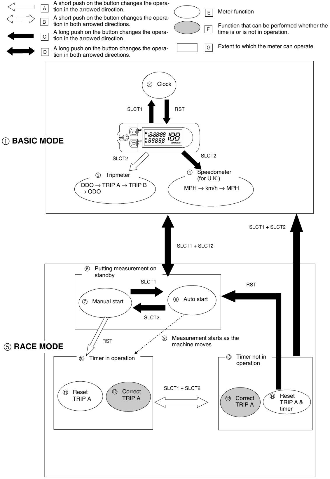
DIAGRAMME DE FONCTIONNEMENT
N.B.:
Always use the recommended fuel as stated below. Also, be sure to use new gasoline.

Recommended fuel: Premium unleaded gasoline only with a research octane number of 95 or higher.
CAUTION:
Use only unleaded gasoline. The use of leaded gasoline will cause severe damage to the engine internal parts such as valves, piston rings, and exhaust system, etc.
NOTE:
If knocking or pinging occurs, use a different brand of gasoline or higher octane grade.
WARNING
- For refueling, be sure to stop the engine and use enough care not to spill any fuel. Also be sure to avoid refueling close to a fire.
- Refuel after the engine, exhaust pipe, etc. have cooled off.
Gasohol (For Canada)
There are two types of gasohol: gasohol containing ethanol and that containing methanol. Gasohol containing ethanol can be used if the ethanol content does not exceed 10% . Gasohol containing methanol is not recommended by Yamaha because it can cause damage to the fuel system or vehicle performance problems.
CARBURANT
Never start or run the engine in a closed area. The exhaust fumes are poisonous; they can cause loss of consciousness and death in a very short time. Always operate the machine in a well-ventilated area.
CAUTION:
- The carburetor on this machine has a built-in accelerator pump. Therefore, when starting the engine, do not operate the throttle or the spark plug will foul.
- Unlike a two-stroke engine, this engine cannot be kick started when the throttle is open because the kickstarter may kick back. Also, if the throttle is open the air/fuel mixture may be too lean for the engine to start.
- Before starting the machine, perform the checks in the pre-operation check list.
According to "AIR FILTER CLEANING" section in the CHAPTER 3, apply the foam-air-filter oil or its equivalent to the element. (Excess oil in the element may adversely affect engine starting.)
STARTING A COLD ENGINE
NOTE:
This model is equipped with an ignition circuit cut-off system. The engine can be started under the following conditions.
- When the transmission is in neutral.
- When the clutch is disengaged with the transmission in any position. However, it is recommended to shift into neutral before starting the engine.
MAINTENANCE DU Filtre A AIR
- Inspect the coolant level.
- Turn the fuel cock to "ON".
- Push on the main switch to "ON".
- Shift the transmission into neutral.
- Fully open the cold starter knob ①.
- Start the engine by pushing the start switch or by kicking the kickstarter crank.
NOTE:
If the engine fails to start by pushing the start switch, release the switch, wait a few seconds, and then try again. Each starting attempt should be as short as possible to preserve the battery. Do not crank the engine more than 10 seconds on any one attempt. If the engine does not start with the starter motor, try using the kickstarter crank.
WARNING
- If the starter motor will not turn when pushing the start switch, stop pushing it immediately and kick start the engine in order to avoid the load on the motor.
-
Do not open the throttle while kicking the kickstarter crank. Otherwise, the kickstarter crank may kick back.
-
Return the cold starter knob to its original position and run the engine at 3,000 5,000 r/min for 1 or 2 minutes.
NOTE:
Since this model is equipped with an accelerator pump, if the engine is raced (the throttle opened and closed), the air/fuel mixture will be too rich and the engine may stall. Also unlike a two-stroke engine, this model can idle.
CAUTION:
Do not warm up the engine for extended periods of time.
Do not operate the cold starter knob and throttle. Pull the hot starter lever ① and start the engine by pushing the start switch or by kicking the kickstarter crank forcefully with a firm stroke.
As soon as the engine starts, Release the hot starter lever to close the air passage.
Restarting an engine after a fall
Pull the hot starter lever and start the engine. As soon as the engine starts, Release the hot starter lever to close the air passage.
The engine fails to start
Pull the hot starter lever all the way out and while holding the lever, kick the kickstarter crank 10 to 20 times to clear the engine.
Then, restart the engine.
Refer to "Restarting an engine after a fall".
| Throttle grip operation* | Cold starter knob | Hot starter lever | ||
| Starting a cold engine | Air temperature = less than 5 °C (41 °F) | Open 3 or 4 times | ON | OFF |
| Air temperature = more than 5 °C (41 °F) | None | ON | OFF | |
| Air temperature (normal temperature) = between 5 °C (41 °F) and 25 °C (77 °F) | None | ON/OFF | OFF | |
| Air temperature = more than 25 °C (77 °F) | None | OFF | OFF | |
| Starting an engine after a long period of time | None | ON | OFF | |
| Restarting a warm engine | None | OFF | ON | |
| Restarting an engine after a fall | None | OFF | ON | |
- Operate the throttle grip before kick starting.
CAUTION:
Observe the following break-in procedures during initial operation to ensure optimum performance and avoid engine damage.
MISE EN MARCHE A CHAUD
- Before starting the engine, fill the fuel tank with the fuel.
- Perform the pre-operation checks on the machine.
- Start and warm up the engine. Check the idle speed, and check the operation of the controls and the engine stop switch. Then, restart the engine and check its operation within no more than 5 minutes after it is restarted.
- Operate the machine in the lower gears at moderate throttle openings for five to eight minutes.
- Check how the engine runs when the machine is ridden with the throttle 1/4 to 1/2 open (low to medium speed) for about one hour.
- Restart the engine and check the operation of the machine throughout its entire operating range. Restart the machine and operate it for about 10 to 15 more minutes.
CAUTION:
After the break-in or before each ride, you must check the entire machine for loose fittings and fasteners as per "TORQUE-CHECK POINTS".
Tighten all such fasteners as required.
PROCEDURE DE RODAGE
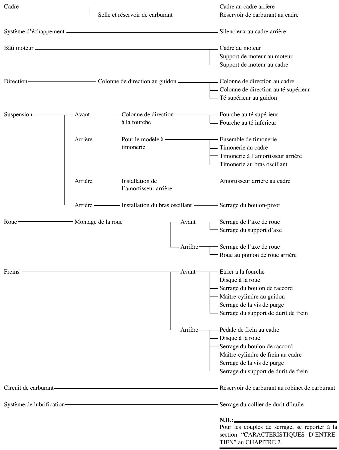
NOTE: Concerning the tightening torque, refer to "MAINTENANCE SPECIFICATIONS" section in the CHAPTER 2.
POINTS DE VERIFICATION DES COUPLES DE SERRAGE
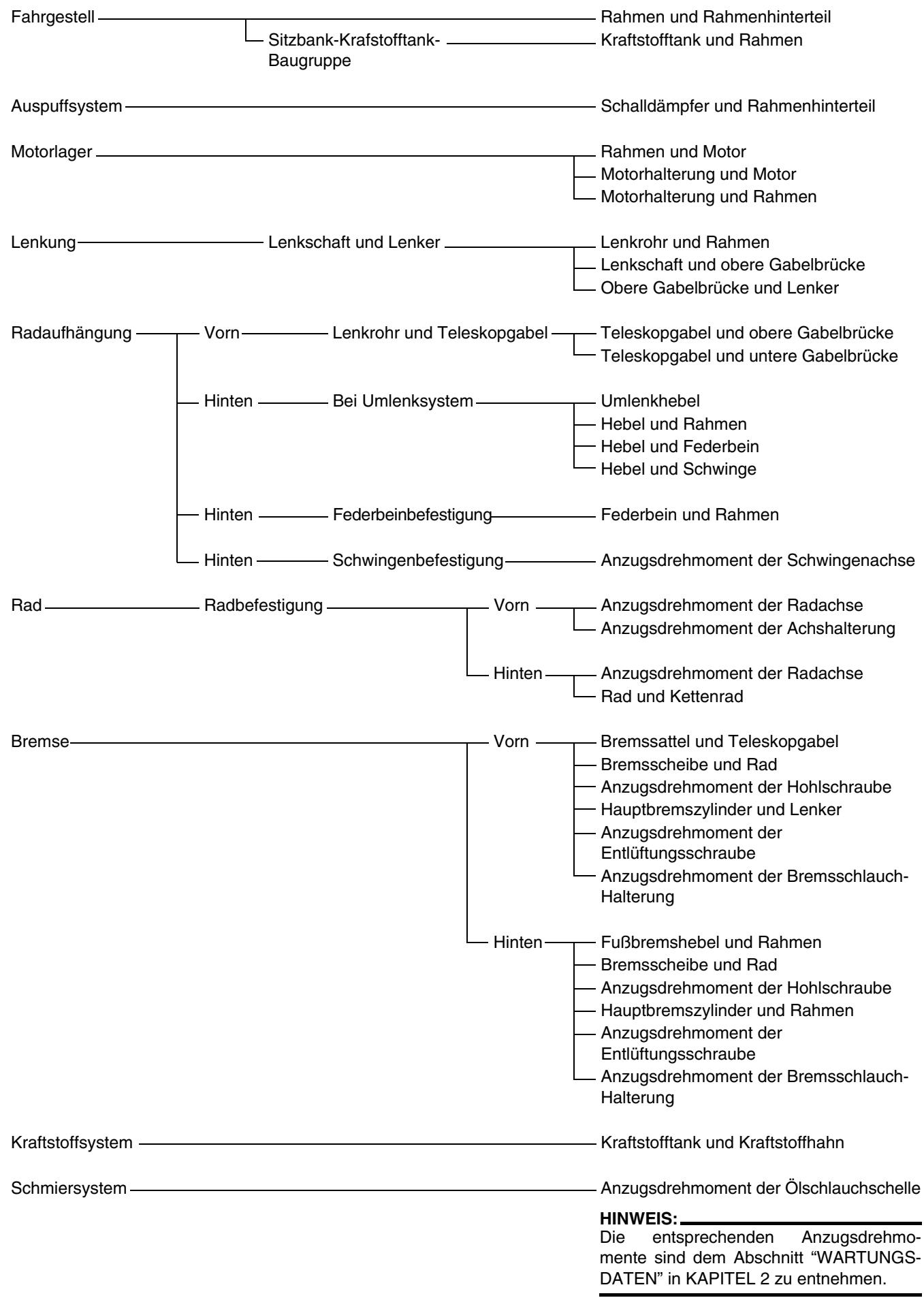
ANZUGSDREHMOMENTE KONTROLLIEREN
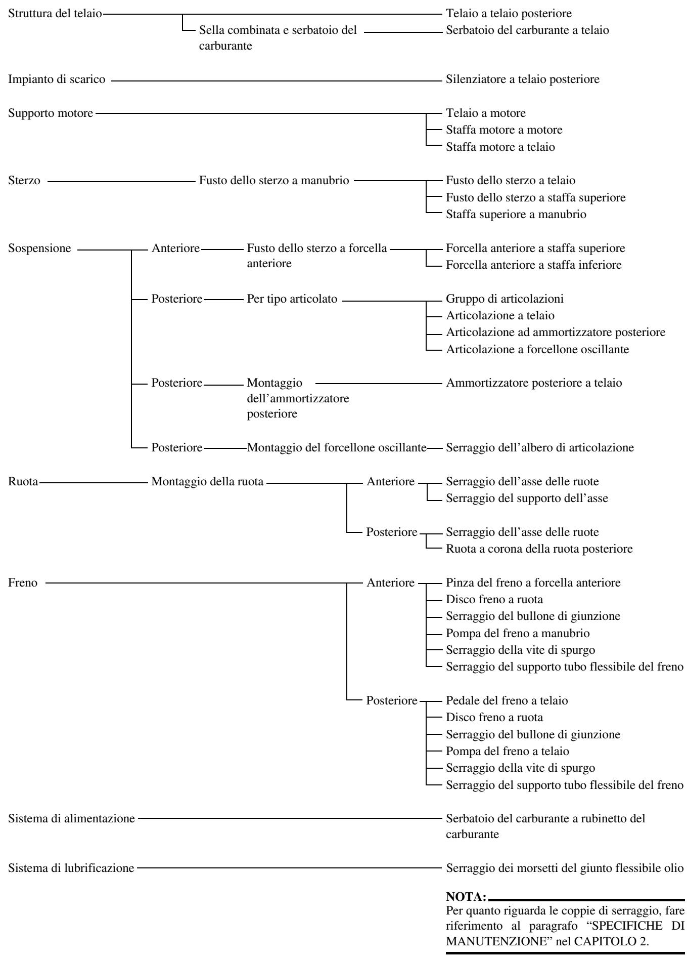
PUNTI DI CONTROLLO SERRAGGIO
CLEANING AND STORAGE
EC1B1000
CLEANING
Frequent cleaning of your machine will enhance its appearance, maintain good overall performance, and extend the life of many components.
- Before washing the machine, block off the end of the exhaust pipe to prevent water from entering. A plastic bag secured with a rubber band may be used for this purpose.
- If the engine is excessively greasy, apply some degreaser to it with a paint brush. Do not apply degreaser to the chain, sprockets, or wheel axles.
- Rinse the dirt and degreaser off with a garden hose; use only enough pressure to do the job.
CAUTION:
Excessive hose pressure may cause water seepage and contamination of wheel bearings, front forks, brakes and transmission seals. Many expensive repair bills have resulted from improper high pressure detergent applications such as those available in coin-operated car washers.
- After the majority of the dirt has been hosed off, wash all surfaces with warm water and a mild detergent. Use an old toothbrush to clean hard-to-reach places.
- Rinse the machine off immediately with clean water, and dry all surfaces with a soft towel or cloth.
- Immediately after washing, remove excess water from the chain with a paper towel and lubricate the chain to prevent rust.
- Clean the seat with a vinyl upholstery cleaner to keep the cover pliable and glossy.
- Automotive wax may be applied to all painted or chromed surfaces. Avoid combination cleaner-waxes, as they may contain abrasives.
- After completing the above, start the engine and allow it to idle for several minutes.
NETTOYAGE ET REMISAGE
NETTOYAGE
If your machine is to be stored for 60 days or more, some preventive measures must be taken to avoid deterioration. After cleaning the machine thoroughly, prepare it for storage as follows:
- Drain the fuel tank, fuel lines, and the carburetor float bowl.
- Remove the spark plug, pour a tablespoon of SAE 10W-30 motor oil in the spark plug hole, and reinstall the plug. With the engine stop switch pushed in, kick the engine over several times to coat the cylinder walls with oil.
- Remove the drive chain, clean it thoroughly with solvent, and lubricate it. Reinstall the chain or store it in a plastic bag tied to the frame.
- Lubricate all control cables.
- Block the frame up to raise the wheels off the ground.
- Tie a plastic bag over the exhaust pipe outlet to prevent moisture from entering.
- If the machine is to be stored in a humid or salt-air environment, coat all exposed metal surfaces with a film of light oil. Do not apply oil to rubber parts or the seat cover.
NOTE:
Make any necessary repairs before the machine is stored.
REMISAGE
| Model name: | WR250FW (USA, CDN, AUS, NZ)WR250F (EUROPE, ZA) | |
| Model code number: | 5UME (USA)5UMF (EUROPE)5UMG (CDN, AUS, NZ, ZA) | |
| Dimensions:Overall lengthOverall widthOverall heightSeat heightWheelbaseMinimum ground clearance | USA, ZA, CDN | EUROPE, AUS, NZ |
| 2,165 mm (85.24 in)825 mm (32.48 in)1,300 mm (51.18 in)980 mm (38.58 in)1,480 mm (58.27 in)365 mm (14.37 in) | 2,180 mm (85.83 in)←1,305 mm (51.38 in)990 mm (38.98 in)←370 mm (14.57 in) | |
| Dry weight:Without oil and fuel | 106.0 kg (233.7 lb) | |
| Engine:Engine typeCylinder arrangementDisplacementBore × strokeCompression ratioStarting system | Liquid cooled 4-stroke, DOHCSingle cylinder, forward inclined249 cm3(8.76 Imp oz, 8.42 US oz)77.0 × 53.6 mm (3.03 × 2.11 in)12.5 : 1Kick and electric starter | |
| Lubrication system: | Dry sump | |
| Oil type or grade:Engine oilYAMALUBE 4(10W-30) or SAE 10W-30YAMALUBE 4(20W-40) or SAE 20W-40YAMALUBE 4-R(10W-50) or SAE 10W-50°C-20 -10 0 10 20 30 40 50 °C-20 -10 0 10 20 30 40 50 °C | (For USA and CDN)Yamalube 4, SAE10W30 or SAE20W40Yamalube 4-R, SAE10W50API service SG type or higher,JASO standard MA(Except for USA and CDN)SAE10W30, SAE10W40, SAE15W40, SAE20W40 or SAE20W50API service SG type or higher,JASO standard MA | |
| Oil capacity: Engine oil Periodic oil change | 1.1 L (0.97 Imp qt, 1.16 US qt) 1.2 L (1.06 Imp qt, 1.27 US qt) 1.4 L (1.23 Imp qt, 1.48 US qt) | |
| With oil filter replacement | ||
| Total amount | ||
| Coolant capacity (including all routes): | 0.99 L (0.87 Imp qt, 1.05 US qt) | |
| Air filter: | Wet type element | |
| Fuel: | ||
| Type | Premium unleaded gasoline only with a research octane number of 95 or higher. | |
| Tank capacity | 8.0 L (1.76 Imp gal, 2.11 US gal) | |
| Reserve | 1.1 L (0.24 Imp gal, 0.29 US gal) | |
| Carburetor: | ||
| Type | FCR-MX37 | |
| Manufacturer | KEIHIN | |
| Spark plug: | ||
| Type/manufacturer | CR9E/NGK (resistance type) | |
| Gap | 0.7 ~ 0.8 mm (0.028 ~ 0.031 in) | |
| Clutch type: | Wet, multiple-disc | |
| Transmission: | ||
| Primary reduction system | Gear | |
| Primary reduction ratio | 57/17 (3.353) | |
| Secondary reduction system | Chain drive | |
| Secondary reduction ratio | 50/13 (3.846) | |
| Transmission type | Constant mesh, 5-speed | |
| Operation | Left foot operation | |
| Gear ratio: 1st | 31/13 (2.385) | |
| 2nd | 28/16 (1.750) | |
| 3rd | 23/17 (1.353) | |
| 4th | 23/21 (1.095) | |
| 5th | 17/19 (0.895) | |
| Chassis: | USA, ZA, CDN | EUROPE, AUS, NZ |
| Frame type | Semi double cradle | ← |
| Caster angle | 27.0° | 26.6° |
| Trail | 115 mm (4.53 in) | 114 mm (4.49 in) |
| Tire: | ||
| Type | With tube | |
| Size (front) | 80/100-21 51M (For USA, CDN and ZA) | |
| Size (rear) | 90/90-21 54R (For EUROPE, AUS and NZ) | |
| Tire pressure (front and rear) | 100/100-18 59M (For USA, CDN and ZA) | |
| Tire pressure (front and rear) | 130/90-18 69R (For EUROPE, AUS and NZ) | |
| Tire pressure (front and rear) | 100 kPa (1.0 kgf/cm2, 15 psi) | |
| Brake: Front brake type | Single disc brake | |
| Operation | Right hand operation | |
| Rear brake type | Single disc brake | |
| Operation | Right foot operation | |
| Suspension: Front suspension | Telescopic fork | |
| Rear suspension | Swingarm (link type monocross suspension) | |
| Shock absorber: Front shock absorber | Coil spring/oil damper | |
| Rear shock absorber | Coil spring/gas, oil damper | |
| Wheel travel: Front wheel travel | 300 mm (11.8 in) | |
| Rear wheel travel | 310 mm (12.2 in) | |
| Electrical: Ignition system | CDI | |
| Generator system | AC magneto | |
| Battery type | YTX5L-BS | |
| Battery voltage/capacity | 12 V/4 AH | |
| Specific gravity | 1.320 | |
| Headlight type: | Quartz bulb (halogen) | |
| Bulb wattage × quantity: Headlight | 12 V 35/36.5 W × 1 | |
| Tailight | 12 V 1.6/0.3 W × 1 | |
MAINTENANCE SPECIFICATIONS
ENGINE
| Item | Standard | Limit | ||
| Cylinder head: Warp limit | ---- | 0.05 mm (0.002 in) | ||
| Cylinder: Bore size | 77.00 ~ 77.01 mm (3.0315 ~ 3.0319 in) | ---- | ||
| Out of round limit | ---- | 0.05 mm (0.002 in) | ||
| Camshaft: Drive method | Chain drive (Left) | ---- | ||
| Camshaft cap inside diameter | 22.000 ~ 22.021 mm (0.8661 ~ 0.8670 in) | ---- | ||
| Camshaft outside diameter | 21.959 ~ 21.972 mm (0.8645 ~ 0.8650 in) | ---- | ||
| Shaft-to-cap clearance | 0.028 ~ 0.062 mm (0.0011 ~ 0.0024 in) | 0.08 mm (0.003 in) | ||
| Cam dimensions | ||||
| Intake | “A” | 29.65 ~ 29.75 mm (1.1673 ~ 1.1713 in) | ||
| “B” | 22.45 ~ 22.55 mm (0.8839 ~ 0.8878 in) | |||
| Exhaust | “A” | 30.399 ~ 30.499 mm (1.1968 ~ 1.2007 in) | ||
| “B” | 22.45 ~ 22.55 mm (0.8839 ~ 0.8878 in) | |||
| Camshaft runout limit | ---- | |||
| Item | Standard | Limit | ||
| Timing chain: Timing chain type/No. of links Timing chain adjustment method | 92RH2010-114M/114 Automatic | ---- ---- | ||
| Valve, valve seat, valve guide: Valve clearance (cold) Head diameter | IN EX | 0.10 ~ 0.15 mm (0.0039 ~ 0.0059 in) 0.17 ~ 0.22 mm (0.0067 ~ 0.0087 in) | ---- ---- | |
| Face width | Seat width | Margin thickness | ||
| “A” head diameter | IN | 22.9 ~ 23.1 mm (0.9016 ~ 0.9094 in) | ---- | |
| EX | 24.4 ~ 24.6 mm (0.9606 ~ 0.9685 in) | ---- | ||
| “B” face width | IN | 2.26 mm (0.089 in) | ---- | |
| EX | 2.26 mm (0.089 in) | ---- | ||
| “C” seat width | IN | 0.9 ~ 1.1 mm (0.0354 ~ 0.0433 in) | 1.6 mm (0.0630 in) | |
| EX | 0.9 ~ 1.1 mm (0.0354 ~ 0.0433 in) | 1.6 mm (0.0630 in) | ||
| “D” margin thickness | IN | 0.8 mm (0.0315 in) | ---- | |
| EX | 0.7 mm (0.0276 in) | ---- | ||
| Stem outside diameter | IN | 3.975 ~ 3.990 mm (0.1565 ~ 0.1571 in) | 3.945 mm (0.1553 in) | |
| EX | 4.460 ~ 4.475 mm (0.1756 ~ 0.1762 in) | 4.430 mm (0.1744 in) | ||
| Guide inside diameter | IN | 4.000 ~ 4.012 mm (0.1575 ~ 0.1580 in) | 4.050 mm (0.1594 in) | |
| EX | 4.500 ~ 4.512 mm (0.1772 ~ 0.1776 in) | 4.550 mm (0.1791 in) | ||
| Stem-to-guide clearance | IN | 0.010 ~ 0.037 mm (0.0004 ~ 0.0015 in) | 0.08 mm (0.003 in) | |
| EX | 0.025 ~ 0.052 mm (0.0010 ~ 0.0020 in) | 0.10 mm (0.004 in) | ||
| Stem runout limit Valve seat width IN EX | ---- | 0.01 mm (0.0004 in) | ||
| 0.9 ~ 1.1 mm (0.0354 ~ 0.0433 in) | 1.6 mm (0.0630 in) | |||
| 0.9 ~ 1.1 mm (0.0354 ~ 0.0433 in) | 1.6 mm (0.0630 in) | |||
| Valve spring: Free length | IN | 36.58 mm (1.44 in) | 35.58 mm (1.40 in) | |
| EX | 37.54 mm (1.48 in) | 36.54 mm (1.44 in) | ||
| Set length (valve closed) | IN | 29.13 mm (1.15 in) | ---- | |
| EX | 29.30 mm (1.15 in) | ---- | ||
| Compressed force (installed) | IN | 103 ~ 118 N at 29.13 mm (10.50 ~ 12.09 kg at 29.13 mm, 23.15 ~ 26.66 lb at 1.15 in) | ---- | |
| EX | 126 ~ 144 N at 29.30 mm (12.85 ~ 14.68 kg at 29.30 mm, 28.32 ~ 32.37 lb at 1.15 in) | ---- | ||
| Tilt limit* | IN | ---- | 2.5°/1.6 mm (2.5°/0.063 in) | |
| EX | ---- | 2.5°/1.6 mm (2.5°/0.063 in) | ||
| Direction of winding (top view) | IN | Clockwise | ---- | |
| EX | Clockwise | ---- | ||
| Piston: Piston to cylinder clearance | 0.030 ~ 0.055 mm (0.0012 ~ 0.0022 in) | 0.1 mm (0.004 in) | ||
| Piston size “D” | 76.955 ~ 76.970 mm (3.0297 ~ 3.0303 in) | ---- | ||
| Measuring point “H” | 8 mm (0.31 in) | ---- | ||
| Piston off-set | 0.5 mm (0.020 in)/IN-side | ---- | ||
| Item | Standard | Limit | ||
| Piston pin bore inside diameter | 16.002 ~ 16.013 mm | 16.043 mm | ||
| (0.6300 ~ 0.6304 in) | (0.6316 in) | |||
| Piston pin outside diameter | 15.991 ~ 16.000 mm | 15.971 mm | ||
| (0.6296 ~ 0.6299 in) | (0.6288 in) | |||
| Piston rings: | ||||
| Top ring: | ||||
| Type | Barrel | ---- | ||
| Dimensions (B × T) | 0.90 × 2.75 mm (0.04 × 0.11 in) | ---- | ||
| End gap (installed) | 0.15 ~ 0.25 mm | 0.50 mm | ||
| (0.006 ~ 0.010 in) | (0.020 in) | |||
| Side clearance (installed) | 0.030 ~ 0.065 mm | 0.12 mm | ||
| (0.0012 ~ 0.0026 in) | (0.005 in) | |||
| 2nd ring: | ||||
| Type | Taper | ---- | ||
| Dimensions (B × T) | 0.80 × 2.75 mm (0.03 × 0.11 in) | ---- | ||
| End gap (installed) | 0.30 ~ 0.45 mm | 0.80 mm | ||
| (0.012 ~ 0.018 in) | (0.031 in) | |||
| Side clearance | 0.020 ~ 0.055 mm | 0.12 mm | ||
| (0.0008 ~ 0.0022 in) | (0.005 in) | |||
| Oil ring: | ||||
| Dimensions (B × T) | 1.50 × 2.25 mm (0.06 × 0.09 in) | ---- | ||
| End gap (installed) | 0.10 ~ 0.40 mm | ---- | ||
| (0.004 ~ 0.016 in) | ||||
| Crankshaft: | ||||
| Crank width “A” | 55.95 ~ 56.00 mm | ---- | ||
| Runout limit “C” | (2.203 ~ 2.205 in) | 0.05 mm | ||
| 0.03 mm (0.0012 in) | (0.002 in) | |||
| Big end side clearance “D” | 0.15 ~ 0.45 mm | 0.50 mm | ||
| (0.0059 ~ 0.0177 in) | (0.02 in) | |||
| Small end free play “F” | 0.4 ~ 1.0 mm (0.02 ~ 0.04 in) | 2.0 mm | ||
| (0.08 in) | ||||
| Clutch: | ||||
| Friction plate thickness | 2.9 ~ 3.1 mm (0.114 ~ 0.122 in) | 2.7 mm(0.106 in) | ||
| Quantity | 9 | ---- | ||
| Clutch plate thickness | 1.1 ~ 1.3 mm (0.043 ~ 0.051 in) | ---- | ||
| Quantity | 8 | ---- | ||
| Warp limit | ---- | 0.1 mm(0.004 in) | ||
| Clutch spring free length | 37.0 mm (1.46 in) | 36.0 mm(1.42 in) | ||
| Quantity | 5 | ---- | ||
| Clutch housing thrust clearance | 0.10 ~ 0.35 mm(0.0039 ~ 0.0138 in) | ---- | ||
| Clutch housing radial clearance | 0.010 ~ 0.044 mm(0.0004 ~ 0.0017 in) | ---- | ||
| Clutch release method | Inner push, cam push | ---- | ||
| Shifter: | ||||
| Shifter type | Cam drum and guide bar | ---- | ||
| Guide bar bending limit | ---- | 0.05 mm(0.002 in) | ||
| Kickstarter: | ||||
| Type | Kick and ratchet type | ---- | ||
| Carburetor: | ||||
| Type/manufacturer | FCR-MX37/KEIHIN | |||
| I. D. mark | 5UME E0 | |||
| Main jet (M.J) | #170 | |||
| Main air jet (M.A.J) | #115 | |||
| Jet needle (J.N) | NJRU | |||
| Cutaway (C.A) | 1.5 | |||
| Pilot jet (P.J) | #42 | |||
| Pilot air jet (P.A.J) | #70 | |||
| Pilot outlet (P.O) | ø0.9 | |||
| Bypass (B.P) | ø1.0 | |||
| Valve seat size (V.S) | ø3.8 | |||
| Starter jet (G.S) | #68 | |||
| Leak jet (Acc.P) | #70 | |||
| Float height (F.H) | 8 mm (0.31 in) | |||
| Engine idle speed | 1,750 ~ 1,950 r/min | |||
| Intake vacuum | 31.3 ~ 36.7 kPa(235 ~ 275 mmHg,9.25 ~ 10.83 inHg) | |||
| Hot starter lever free play | 3 ~ 6 mm(0.12 ~ 0.24 in) | |||
| Lubrication system: | ||||
| Oil filter type | Paper type | ---- | ||
| Oil pump type | Trochoid type | ---- | ||
| Tip clearance | 0.12 mm or less(0.0047 in or less) | 0.20 mm(0.008 in) | ||
| Side clearance | 0.09 ~ 0.17 mm(0.0035 ~ 0.0067 in) | 0.24 mm(0.009 in) | ||
| Housing and rotor clearance | 0.03 ~ 0.10 mm(0.0012 ~ 0.0039 in) | 0.17 mm(0.0067 in) | ||
| Cooling: | ||||
| Radiator core size | ||||
| Width | 120.2 mm (4.73 in) | ---- | ||
| Height | 240 mm (9.45 in) | ---- | ||
| Thickness | 22 mm (0.87 in) | ---- | ||
| Radiator cap opening pressure | 110 kPa (1.1 kg/cm2, 15.6 psi) | ---- | ||
| Radiator capacity (total) | 0.54 L (0.48 Imp qt, 0.57 US qt) | ---- | ||
| Water pump | ||||
| Type | Single-suction centrifugal pump | ---- | ||
| Part to be tightened | Thread size | Q'ty | Tightening torque | ||
| Nm | m·kg | ft·lb | |||
| Spark plug | M10S × 1.0 | 1 | 13 | 1.3 | 9.4 |
| Camshaft cap | M6 × 1.0 | 10 | 10 | 1.0 | 7.2 |
| Cylinder head blind plug screw | M12 × 1.0 | 1 | 28 | 2.8 | 20 |
| Cylinder head (stud bolt) | M6 × 1.0 | 2 | 7 | 0.7 | 5.1 |
| (stud bolt) | M8 × 1.25 | 1 | 15 | 1.5 | 11 |
| (bolt) | M9 × 1.25 | 4 | 38 | 3.8 | 27 |
| (nut) | M6 × 1.0 | 2 | 10 | 1.0 | 7.2 |
| Cylinder head cover | M6 × 1.0 | 2 | 10 | 1.0 | 7.2 |
| Cylinder | M6 × 1.0 | 1 | 10 | 1.0 | 7.2 |
| Balancer weight | M6 × 1.0 | 2 | 10 | 1.0 | 7.2 |
| Balancer shaft driven gear | M14 × 1.0 | 1 | 50 | 5.0 | 36 |
| Timing chain guide (intake side) | M6 × 1.0 | 2 | 10 | 1.0 | 7.2 |
| Timing chain tensioner | M6 × 1.0 | 2 | 10 | 1.0 | 7.2 |
| Timing chain tensioner cap bolt | M6 × 1.0 | 1 | 7 | 0.7 | 5.1 |
| Impeller | M8 × 1.25 | 1 | 14 | 1.4 | 10 |
| Radiator hose clamp | M6 × 1.0 | 10 | 2 | 0.2 | 1.4 |
| Coolant drain bolt | M6 × 1.0 | 1 | 10 | 1.0 | 7.2 |
| Water pump housing | M6 × 1.0 | 4 | 10 | 1.0 | 7.2 |
| Radiator stay | M6 × 1.0 | 6 | 10 | 1.0 | 7.2 |
| Radiator | M6 × 1.0 | 4 | 10 | 1.0 | 7.2 |
| Radiator pipe | M6 × 1.0 | 1 | 10 | 1.0 | 7.2 |
| Oil pump cover | M4 × 0.7 | 1 | 2 | 0.2 | 1.4 |
| Oil pump | M6 × 1.0 | 3 | 10 | 1.0 | 7.2 |
| Oil filter element drain bolt | M6 × 1.0 | 1 | 10 | 1.0 | 7.2 |
| Oil filter element cover | M6 × 1.0 | 2 | 10 | 1.0 | 7.2 |
| Oil strainer (crankcase) | M6 × 1.0 | 2 | 10 | 1.0 | 7.2 |
| Oil delivery pipe 1(M10) | M10 × 1.25 | 1 | 20 | 2.0 | 14 |
| (M8) | M8 × 1.25 | 2 | 18 | 1.8 | 13 |
| Oil hose | M6 × 1.0 | 2 | 8 | 0.8 | 5.8 |
| Oil hose clamp | — | 2 | 2 | 0.2 | 1.4 |
| Oil strainer (oil tank) | M6 × 1.0 | 1 | 9 | 0.9 | 6.5 |
| Oil tank drain bolt | M8 × 1.25 | 1 | 18 | 1.8 | 13 |
| Oil tank (upper) | M6 × 1.0 | 1 | 7 | 0.7 | 5.1 |
| Oil tank and frame | M6 × 1.0 | 3 | 9 | 0.9 | 6.5 |
| Oil pressure check bolt | M6 × 1.0 | 1 | 10 | 1.0 | 7.2 |
| Carburetor joint | M6 × 1.0 | 2 | 10 | 1.0 | 7.2 |
| Carburetor joint clamp | M4 × 0.7 | 1 | 3 | 0.3 | 2.2 |
| Air filter joint clamp | M6 × 1.0 | 1 | 3 | 0.3 | 2.2 |
| Throttle cable adjust bolt and locknut | M6 × 0.75 | 1 | 4 | 0.4 | 2.9 |
| Throttle cable (pull) | M6 × 1.0 | 1 | 4 | 0.4 | 2.9 |
| Throttle cable (return) | M12 × 1.0 | 1 | 11 | 1.1 | 8.0 |
| Throttle cable cover | M5 × 0.8 | 2 | 4 | 0.4 | 2.9 |
| Hot starter plunger | M12 × 1.0 | 1 | 2 | 0.2 | 1.4 |
| Hot starter cable adjust bolt and locknut | M6 × 0.75 | 1 | 4 | 0.4 | 2.9 |
| Air filter case | M6 × 1.0 | 2 | 8 | 0.8 | 5.8 |
| Air filter joint and air filter case | M5 × 0.8 | 1 | 4 | 0.4 | 2.9 |
| Exhaust pipe | M8 × 1.25 | 2 | 20 | 2.0 | 14 |
| Exhaust pipe protector | M6 × 1.0 | 3 | 10 | 1.0 | 7.2 |
| Silencer | M8 × 1.25 | 2 | 30 | 3.0 | 22 |
| Silencer clamp | M8 × 1.25 | 1 | 16 | 1.6 | 11 |
| Spark arrester | M5 × 0.8 | 4 | 7 | 0.7 | 5.1 |
| Silencer cap | M5 × 0.8 | 6 | 5 | 0.5 | 3.6 |
| Air induction pipe | M6 × 1.0 | 1 | 10 | 1.0 | 7.2 |
| Air induction pipe clamp | M6 × 1.0 | 1 | 4 | 0.4 | 2.9 |
| Air cut-off valve assembly and bracket | M6 × 1.0 | 2 | 10 | 1.0 | 7.2 |
| Bracket (air cut-off valve) and frame | M6 × 1.0 | 2 | 7 | 0.7 | 5.1 |
| Crankcase | M6 × 1.0 | 11 | 12 | 1.2 | 8.7 |
| Crankcase bearing stopper | M6 × 1.0 | 11 | 10 | 1.0 | 7.2 |
| Crankcase bearing stopper (crankshaft) | M6 × 1.0 | 4 | 10 | 1.0 | 7.2 |
| Left crankcase cover | M6 × 1.0 | 8 | 10 | 1.0 | 7.2 |
| Idle gear cover (starter motor) | M6 × 1.0 | 3 | 10 | 1.0 | 7.2 |
| Idle gear plate | M6 × 1.0 | 2 | 10 | 1.0 | 7.2 |
| Right crankcase cover | M6 × 1.0 | 6 | 10 | 1.0 | 7.2 |
| Clutch cover | M6 × 1.0 | 7 | 10 | 1.0 | 7.2 |
| Crankcase oil drain bolt | M10 × 1.25 | 1 | 20 | 2.0 | 14 |
| Drive chain sprocket cover | M6 × 1.0 | 2 | 8 | 0.8 | 5.8 |
| Kick shaft ratchet wheel guide | M6 × 1.0 | 2 | 12 | 1.2 | 8.7 |
| Kickstarter crank | M8 × 1.25 | 1 | 33 | 3.3 | 24 |
| Primary drive gear | M18 × 1.0 | 1 | 75 | 7.5 | 54 |
| Clutch spring | M6 × 1.0 | 5 | 10 | 1.0 | 7.2 |
| Clutch boss | M16 × 1.0 | 1 | 60 | 6.0 | 43 |
| Clutch cable locknut | M8 × 1.25 | 2 | 7 | 0.7 | 5.1 |
| Push lever shaft | M6 × 1.0 | 1 | 10 | 1.0 | 7.2 |
| Drive sprocket | M18 × 1.0 | 1 | 75 | 7.5 | 54 |
| Drive axle oil seal stopper | M6 × 1.0 | 2 | 10 | 1.0 | 7.2 |
| Segment | M8 × 1.25 | 1 | 30 | 3.0 | 22 |
| Shift guide | M6 × 1.0 | 2 | 10 | 1.0 | 7.2 |
| Stopper lever | M6 × 1.0 | 1 | 10 | 1.0 | 7.2 |
| Shift pedal | M6 × 1.0 | 1 | 12 | 1.2 | 8.7 |
NOTE:
- marked portion shall be checked for torque tightening after break-in.
CHASSIS
| Item | Standard | Limit | ||
| Steering system: Steering bearing type | Taper roller bearing | ---- | ||
| Front suspension: Front fork travel | USA, CDN | EUROPE | AUS, NZ, ZA | |
| 300 mm (11.8 in) | ← | ← | ||
| Fork spring free length | 460 mm (18.1 in) | ← | ← | |
| Spring rate, STD | K = 4.4 N/mm (0.449 kg/mm, 25.1 lb/in) | ← | ← | |
| Optional spring/spacer | Yes | ← | ← | |
| Oil capacity | 648 cm³ (22.8 Imp oz, 21.9 US oz) | ← | ← | |
| Oil level | 132 mm (5.20 in) | ← | ← | |
| <Min. ~ Max.> (From top of outer tube with inner tube and damper rod fully com- pressed without spring.) | 95 ~ 150 mm (3.74 ~ 5.91 in) | ← | ← | |
| Oil grade | Suspension oil “S1” | ← | ← | |
| Inner tube outer diameter | 48 mm (1.89 in) | ← | ← | |
| Front fork top end | 5 mm (0.20 in) | ← | ← | |
| Rear suspension: Shock absorber travel | USA, CDN | EUROPE | AUS, NZ, ZA | |
| 130 mm (5.12 in) | ← | ← | ||
| Spring free length | 260 mm (10.24 in) | ← | ← | |
| Fitting length | 249 mm (9.80 in) | 248.5 mm (9.78 in) | 245.0 mm (9.65 in) | |
| <Min. ~ Max.> | 238.5 ~ 258.5 mm (9.39 ~ 10.18 in) | ← | ← | |
| Spring rate, STD | K = 52.0 N/mm (5.30 kg/mm, 296.8 lb/in) | ← | ← | |
| Optional spring | Yes | ← | ← | |
| Enclosed gas pressure | 1,000 kPa (10 kg/cm², 142 psi) | ← | ← | |
| Swingarm: Swingarm free play limit End | ---- | 1.0 mm (0.04 in) | ||
| Item | Standard | Limit | ||
| Wheel: | USA, CDN, ZA | EUROPE, AUS, NZ | ||
| Front wheel type | Spoke wheel | ← | ---- | |
| Rear wheel type | Spoke wheel | ← | ---- | |
| Front rim size/material | 21 × 1.60/Aluminum | ← | ---- | |
| Rear rim size/material | 18 × 1.85/Aluminum | 18 × 2.15/Aluminum | ---- | |
| Rim runout limit: | ||||
| Radial | ---- | ---- | 2.0 mm (0.08 in) | |
| Lateral | ---- | ---- | 2.0 mm (0.08 in) | |
| Drive chain: | ||||
| Type/manufacturer | DID520VM/DAIDO | ---- | ||
| Number of links | 113 links + joint | ---- | ||
| Chain slack | 48 ~ 58 mm (1.9 ~ 2.3 in) | ---- | ||
| Chain length (15 links) | ---- | 239.3 mm (9.42 in) | ||
| Front disc brake: | ||||
| Disc outside dia. × Thickness | 250 × 3.0 mm (9.84 × 0.12 in) | 250 × 2.5 mm (9.84 × 0.10 in) | ||
| Pad thickness | 4.4 mm (0.17 in) | 1.0 mm (0.04 in) | ||
| Master cylinder inside dia. | 11.0 mm (0.433 in) | ---- | ||
| Caliper cylinder inside dia. | 27.0 mm (1.063 in) × 2 | ---- | ||
| Brake fluid type | DOT #4 | ---- | ||
| Rear disc brake: | ||||
| Disc outside dia. × Thickness | 245 × 4.0 mm (9.65 × 0.16 in) | 245 × 3.5 mm (9.65 × 0.14 in) | ||
| Deflection limit | ---- | 0.15 mm (0.006 in) | ||
| Pad thickness | 6.4 mm (0.25 in) | 1.0 mm (0.04 in) | ||
| Master cylinder inside dia. | 11.0 mm (0.433 in) | ---- | ||
| Caliper cylinder inside dia. | 25.4 mm (1.000 in) × 1 | ---- | ||
| Brake fluid type | DOT #4 | ---- | ||
| Brake lever and brake pedal: | ||||
| Brake lever position | 95 mm (3.74 in) | ---- | ||
| Brake pedal height | 10 mm (0.39 in) | ---- | ||
| (vertical height above footrest top) | ||||
| Clutch lever free play (lever end) | 8 ~ 13 mm (0.31 ~ 0.51 in) | ---- | ||
| Throttle grip free play | 3 ~ 5 mm (0.12 ~ 0.20 in) | ---- | ||
| Part to be tightened | Thread size | Q'ty | Tightening torque | ||
| Nm | m·kg | ft·lb | |||
| Upper bracket and outer tube | M8 × 1.25 | 4 | 21 | 2.1 | 15 |
| Lower bracket and outer tube | M8 × 1.25 | 4 | 21 | 2.1 | 15 |
| Upper bracket and steering stem | M24 × 1.0 | 1 | 145 | 14.5 | 105 |
| Handlebar upper holder and handlebar lower holder | M8 × 1.25 | 4 | 28 | 2.8 | 20 |
| Handlebar lower holder and upper bracket | M10 × 1.25 | 2 | 34 | 3.4 | 24 |
| Steering stem and steering ring nut | M28 × 1.0 | 1 | Refer to NOTE. | ||
| Front fork and front fork cap bolt | M51 × 1.5 | 2 | 30 | 3.0 | 22 |
| Front fork and base valve | M30 × 1.0 | 2 | 55 | 5.5 | 40 |
| Front fork cap bolt and damper rod | M12 × 1.25 | 2 | 29 | 2.9 | 21 |
| Front fork bleed screw and front fork cap bolt | M5 × 0.8 | 2 | 1 | 0.1 | 0.7 |
| Front fork and front fork protector | M6 × 1.0 | 6 | 7 | 0.7 | 5.1 |
| Front fork protector and brake hose holder | M6 × 1.0 | 2 | 7 | 0.7 | 5.1 |
| Throttle grip cap | M5 × 0.8 | 2 | 4 | 0.4 | 2.9 |
| Front brake master cylinder | M6 × 1.0 | 2 | 9 | 0.9 | 6.5 |
| Brake lever mounting bolt | M6 × 1.0 | 1 | 6 | 0.6 | 4.3 |
| Brake lever mounting nut | M6 × 1.0 | 1 | 6 | 0.6 | 4.3 |
| Brake lever position locknut | M6 × 1.0 | 1 | 5 | 0.5 | 3.6 |
| Front brake hose guide and front brake hose guide bracket | M5 × 0.8 | 1 | 4 | 0.4 | 2.9 |
| Front brake hose guide and lower bracket | M6 × 1.0 | 1 | 4 | 0.4 | 2.9 |
| Clutch lever holder | M5 × 0.8 | 2 | 4 | 0.4 | 2.9 |
| Clutch lever mounting nut | M6 × 1.0 | 1 | 4 | 0.4 | 2.9 |
| Hot starter lever holder | M5 × 0.8 | 2 | 4 | 0.4 | 2.9 |
| Hot starter lever mounting nut | M5 × 0.8 | 1 | 2 | 0.2 | 1.4 |
| Front brake master cylinder cap | M4 × 0.7 | 2 | 2 | 0.2 | 1.4 |
| Front brake hose union bolt | M10 × 1.25 | 2 | 30 | 3.0 | 22 |
| Front brake caliper | M8 × 1.25 | 2 | 23 | 2.3 | 17 |
| Front brake caliper and brake hose holder | M6 × 1.0 | 1 | 10 | 1.0 | 7.2 |
| Pad pin plug | M10 × 1.0 | 2 | 3 | 0.3 | 2.2 |
| Front brake caliper and pad pin | M10 × 1.0 | 1 | 18 | 1.8 | 13 |
| Rear brake caliper and pad pin | M10 × 1.0 | 1 | 18 | 1.8 | 13 |
| Brake caliper and bleed screw | M8 × 1.25 | 2 | 6 | 0.6 | 4.3 |
| Front wheel axle and axle nut | M16 × 1.5 | 1 | 90 | 9.0 | 65 |
| Front wheel axle holder | M8 × 1.25 | 4 | 21 | 2.1 | 15 |
| Front brake disc | M6 × 1.0 | 6 | 12 | 1.2 | 8.7 |
| Rear brake disc | M6 × 1.0 | 6 | 14 | 1.4 | 10 |
| Brake pedal | M8 × 1.25 | 1 | 26 | 2.6 | 19 |
| Rear brake master cylinder | M6 × 1.0 | 2 | 10 | 1.0 | 7.2 |
| Rear brake master cylinder cap | M4 × 0.7 | 2 | 2 | 0.2 | 1.4 |
| Rear brake hose union bolt | M10 × 1.25 | 2 | 30 | 3.0 | 22 |
| Rear wheel axle and axle nut | M20 × 1.5 | 1 | 125 | 12.5 | 90 |
NOTE:
1. First, tighten the steering ring nut approximately 38 Nm (3.8 m • kg, 27 ft • lb) by using the steering nut wrench, then loosen the steering ring nut one turn.
2. Retighten the steering ring nut 7 Nm (0.7 m • kg, 5.1 ft • lb).
| Part to be tightened | Thread size | Q'ty | Tightening torque | ||
| Nm | m·kg | ft·lb | |||
| Nipple (spoke) | — | 72 | 3 | 0.3 | 2.2 |
| Rear wheel sprocket | M8 × 1.25 | 6 | 50 | 5.0 | 36 |
| Rear brake disc cover | M6 × 1.0 | 2 | 10 | 1.0 | 7.2 |
| Rear brake caliper protector | M6 × 1.0 | 2 | 7 | 0.7 | 5.1 |
| Drive chain puller adjust bolt and locknut | M8 × 1.25 | 2 | 19 | 1.9 | 13 |
| Engine mounting: | |||||
| Engine and engine bracket (front) | M10 × 1.25 | 1 | 53 | 5.3 | 38 |
| Engine and frame (lower) | M10 × 1.25 | 1 | 53 | 5.3 | 38 |
| Upper engine bracket and frame | M8 × 1.25 | 4 | 34 | 3.4 | 24 |
| Lower engine bracket and frame | M8 × 1.25 | 4 | 34 | 3.4 | 24 |
| Engine and engine bracket (upper) | M10 × 1.25 | 1 | 55 | 5.5 | 40 |
| Engine guard | M6 × 1.0 | 3 | 7 | 0.7 | 5.1 |
| Regulator | M6 × 1.0 | 2 | 7 | 0.7 | 5.1 |
| Pivot shaft and nut | M16 × 1.5 | 1 | 85 | 8.5 | 61 |
| Relay arm and swingarm | M14 × 1.5 | 1 | 70 | 7.0 | 50 |
| Relay arm and connecting rod | M14 × 1.5 | 1 | 80 | 8.0 | 58 |
| Connecting rod and frame | M14 × 1.5 | 1 | 80 | 8.0 | 58 |
| Rear shock absorber and frame | M10 × 1.25 | 1 | 56 | 5.6 | 40 |
| Rear shock absorber and relay arm | M10 × 1.25 | 1 | 53 | 5.3 | 38 |
| Rear frame (upper) | M8 × 1.25 | 1 | 38 | 3.8 | 27 |
| Rear frame (lower) | M8 × 1.25 | 2 | 32 | 3.2 | 23 |
| Swingarm and brake hose holder | M5 × 0.8 | 4 | 2 | 0.2 | 1.4 |
| Swingarm and patch | M4 × 0.7 | 4 | 2 | 0.2 | 1.4 |
| Upper drive chain tensioner | M8 × 1.25 | 1 | 16 | 1.6 | 11 |
| Lower drive chain tensioner | M8 × 1.25 | 1 | 16 | 1.6 | 11 |
| Drive chain support | M6 × 1.0 | 3 | 7 | 0.7 | 5.1 |
| Seal guard and swingarm | M5 × 0.8 | 4 | 6 | 0.6 | 4.3 |
| Fuel tank | M6 × 1.0 | 2 | 9 | 0.9 | 6.5 |
| Fuel cock | M6 × 1.0 | 2 | 4 | 0.4 | 2.9 |
| Seat set bracket and fuel tank | M6 × 1.0 | 1 | 7 | 0.7 | 5.1 |
| Fuel tank bracket and fuel tank | M6 × 1.0 | 4 | 7 | 0.7 | 5.1 |
| Air scoop and fuel tank | M6 × 1.0 | 6 | 7 | 0.7 | 5.1 |
| Air scoop and radiator guard (lower) | M6 × 1.0 | 2 | 6 | 0.6 | 4.3 |
| Front fender | M6 × 1.0 | 4 | 7 | 0.7 | 5.1 |
| Rear fender (front) | M6 × 1.0 | 2 | 7 | 0.7 | 5.1 |
| Rear fender (rear) | M6 × 1.0 | 2 | 11 | 1.1 | 8.0 |
| Side cover | M6 × 1.0 | 2 | 7 | 0.7 | 5.1 |
| Seat | M8 × 1.25 | 2 | 23 | 2.3 | 17 |
| Multi-function display bracket and upper bracket | M6 × 1.0 | 2 | 7 | 0.7 | 5.1 |
| Multi-function display | M5 × 0.8 | 2 | 4 | 0.4 | 2.9 |
| Plate 1 and front fork protector | M5 × 0.8 | 2 | 4 | 0.4 | 2.9 |
| Plate 2 and front fork protector | — | 2 | 0.5 | 0.05 | 0.36 |
MAINTENANCE SPECIFICATIONS

| Part to be tightened | Thread size | Q'ty | Tightening torque | ||
| Nm | m·kg | ft·lb | |||
| Speed sensor lead holder and lower bracket | M6 × 1.0 | 1 | 13 | 1.3 | 9.4 |
| Headlight body and headlight unit | — | 2 | 1 | 0.1 | 0.7 |
| Headlight (left and right) | M6 × 1.0 | 2 | 7 | 0.7 | 5.1 |
| Taillight | — | 3 | 1 | 0.1 | 0.7 |
| Taillight lead clamp and rear fender | — | 3 | 0.5 | 0.05 | 0.36 |
| Catch tank (upper) | M6 × 1.0 | 1 | 16 | 1.6 | 11 |
| Catch tank (lower) | M6 × 1.0 | 1 | 7 | 0.7 | 5.1 |
| Footrest bracket and frame | M10 × 1.25 | 4 | 55 | 5.5 | 40 |
| Sidestand | M10 × 1.25 | 1 | 25 | 2.5 | 18 |
NOTE:
- marked portion shall be checked for torque tightening after break-in.
EC212300
ELECTRICAL
| Item | Standard | Limit |
| Ignition system: Advancer type | Electrical | ---- |
| CDI: Pickup coil resistance (color) | 248 ~ 372 Ω at 20 °C (68 °F) (White - Red) | ---- |
| CDI unit-model/manufacturer | 5UM-E0/YAMAHA (For USA) 5UM-F0/YAMAHA (Except for USA) | ---- |
| Ignition coil: Model/manufacturer | 5UL-10/DENSO | ---- |
| Minimum spark gap | 6 mm (0.24 in) | ---- |
| Primary coil resistance | 0.08 ~ 0.10 Ω at 20 °C (68 °F) | ---- |
| Secondary coil resistance | 4.6 ~ 6.8 kΩ at 20 °C (68 °F) | ---- |
| Charging system: System type | AC magneto | ---- |
| Model (stator)/manufacturer | 5UM 20/YAMAHA | ---- |
| Normal output | 14 V/120 W at 5,000 r/min | ---- |
| Charging coil resistance (color) | 0.288 ~ 0.432 Ω at 20 °C (68 °F) (White - Ground) | ---- |
| Lighting coil resistance (color) | 0.224 ~ 0.336 Ω at 20 °C (68 °F) (Yellow - Ground) | ---- |
| Rectifier/regulator: Regulator type | Semiconductor short circuit | ---- |
| Model/manufacturer | SH770AA/SHINDENGEN | ---- |
| Regulated voltage (AC) | 12.5 ~ 13.5 V | ---- |
| Regulated voltage (DC) | 14.0 ~ 15.0 V | ---- |
| Rectifier capacity (AC) | 12 A | ---- |
| Rectifier capacity (DC) | 8 A | ---- |
| Electric starting system: Type | Constant mesh | ---- |
| Starter motor: Model/manufacturer | 5UM01/YAMAHA | ---- |
| Operation voltage | 12 V | ---- |
| Output | 0.35 kW | ---- |
| Armature coil resistance | 0.0189 ~ 0.0231 Ω at 20 °C (68 °F) | ---- |
| Brush overall length | 7 mm (0.28 in) | 3.5 mm (0.14 in) |
| Brush quantity | 2 pcs. | ---- |
| Spring force | 3.92 ~ 5.88 N (400 ~ 600 g, 14.1 ~ 21.2 oz) | ---- |
| Commutator diameter | 17.6 mm (0.69 in) | 16.6 mm (0.65 in) |
| Mica undercut (depth) | 1.5 mm (0.06 in) | ---- |
MAINTENANCE SPECIFICATIONS
| SPEC |
| Item | Standard | Limit |
| Starter relay: | ||
| Model/manufacturer | 2768090-A/JIDECO | ---- |
| Amperage rating | 180 A | ---- |
| Coil winding resistance | 4.2 ~ 4.6 Ω at 20 °C (68 °F) | ---- |
| Starting circuit cut-off relay: | ||
| Model/manufacturer | ACM33221 M06/MATSUSHITA | ---- |
| Coil winding resistance | 75.69 ~ 92.51 Ω at 20 °C (68 °F) | ---- |
| Fuse (amperage × quantity): | ||
| Main fuse | 10 A × 1 | ---- |
| Reserve fuse | 10 A × 1 | ---- |
| Part to be tightened | Thread size | Q'ty | Tightening torque | ||
| Nm | m·kg | ft·lb | |||
| Stator | M5 × 0.8 | 2 | 7 | 0.7 | 5.1 |
| Holder (AC magneto lead) | M5 × 0.8 | 2 | 7 | 0.7 | 5.1 |
| Rotor | M12 × 1.25 | 1 | Refer to NOTE. | ||
| Neutral switch | M5 × 0.8 | 2 | 4 | 0.4 | 2.9 |
| Starter motor | M6 × 1.0 | 2 | 10 | 1.0 | 7.2 |
| Starter relay terminal | M6 × 1.0 | 2 | 4 | 0.4 | 2.9 |
| Negative lead and cylinder head | M6 × 1.0 | 1 | 10 | 1.0 | 7.2 |
| Pickup coil | M6 × 1.0 | 2 | 10 | 1.0 | 7.2 |
NOTE:
Tighten the rotor nut to 65Nm (6.5 m • kg, 47 ft • lb), loosen and retighten the rotor nut to 65 Nm (6.5 m • kg, 47 ft • lb).
EC220001
GENERAL TORQUE SPECIFICATIONS
This chart specifies torque for standard fasteners with standard I.S.O. pitch threads. Torque specifications for special components or assemblies are included in the applicable sections of this book. To avoid warpage, tighten multi-fastener assemblies in a crisscross fashion, in progressive stages, until full torque is reached. Unless otherwise specified, torque specifications call for clean, dry threads. Components should be at room temperature.
| A (Nut) | B (Bolt) | TORQUE SPECIFICATION | ||
| Nm | m·kg | ft·lb | ||
| 10 mm | 6 mm | 6 | 0.6 | 4.3 |
| 12 mm | 8 mm | 15 | 1.5 | 11 |
| 14 mm | 10 mm | 30 | 3.0 | 22 |
| 17 mm | 12 mm | 55 | 5.5 | 40 |
| 19 mm | 14 mm | 85 | 8.5 | 61 |
| 22 mm | 16 mm | 130 | 13 | 94 |
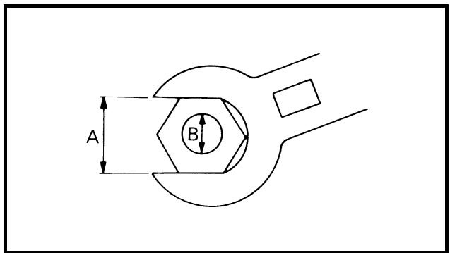
A: Distance between flats
B: Outside thread diameter
EC230000
DEFINITION OF UNITS
| Unit | Read | Definition | Measure |
| mm | millimeter | 10-3meter | Length |
| cm | centimeter | 10-2meter | Length |
| kg | kilogram | 103gram | Weight |
| N | Newton | 1 kg × m/sec2 | Force |
| Nm | Newton meter | N × m | Torque |
| m • kg | Meter kilogram | m × kg | Torque |
| Pa | Pascal | N/m2 | Pressure |
| N/mm | Newton per millimeter | N/mm | Spring rate |
| L | Liter | — | Volume or capacity |
| cm3 | Cubic centimeter | — | Volume or capacity |
| r/min | Revolution per minute | — | Engine speed |
CHARACTERISTIQUES
CHARACTERISTIQUES GENERALES
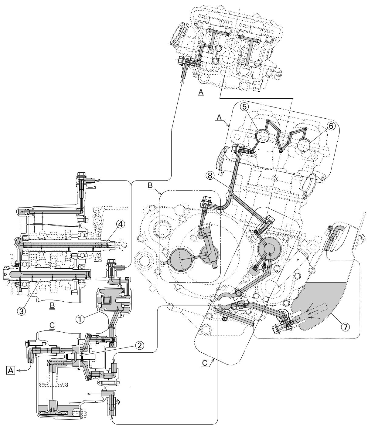
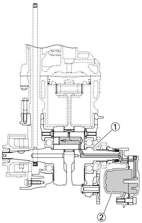
LUBRICATION DIAGRAMS
① Oil filter element
② Oil pump
③ Drive axle
④ Main axle
⑤ Intake camshaft
⑥ Exhaust camshaft
⑦ Oil tank
⑧ Oil delivery pipe
A To oil tank
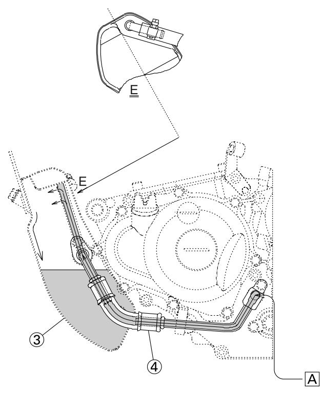
DIAGRAMMES DE LUBRIFICATION
① Crankshaft
② Oil filter element
③ Oil tank
④ Oil hose
A From oil pump
① Fuel tank breather hose
② Clamp
③ Diode
Hot starter cable
⑤ Wire harness
Hump (frame)
⑦ Cylinder head breather hose
⑧ Throttle position sensor lead
Neutral switch lead
Oil hose
11 Clutch cable
12 Starter motor lead
13 Cable guide
Negative battery lead
15 AC magneto lead
16 Brake hose
17 Rectifier/regulator lead
18 Carburetor breather hose
19 Carburetor overflow hose
Catch tank breather hose

DIAGRAMME DE CHEMINEMENT DES CABLES
A Insert the end of the fuel tank breather hose into the hole in the steering stem.
Fasten the throttle cable, hot starter cable and rectifier/regulator lead onto the frame. Locate the clamp end facing the lower side of the hot starter cable and cut off the tie end.
Fasten the diode (at the marking), throttle cable and hot starter cable onto the frame. Locate the clamp end facing toward the lower right of the frame and with the tie end facing downward.
Fasten the wire harness, throttle position sensor lead, starter motor lead and negative battery lead onto the frame. Pass the clamp through the hole in the stay (air cut-off valve). Locate the clamp end facing toward the lower side of the frame and cut off the tie end.
E Fasten the throttle position sensor lead onto the frame. Locate the clamp end facing toward the lower side of the frame and cut off the tie end.
Pass the carburetor breather hoses, carburetor overflow hose and catch tank breather hose between the connecting rod and cross tube (frame).
G Fasten the neutral switch lead and oil hose together with the plastic locking ties and cut off the tie ends.
Fasten the neutral switch lead and AC magneto lead onto the frame. Locate the clamp end facing toward the outside of the frame and tie end facing toward the rear of the frame.
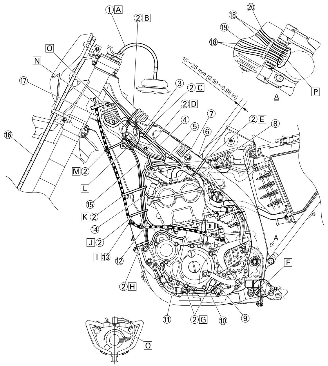
Pass the clutch cable through the cable guide.
Fasten the starter motor lead, AC magneto lead and neutral switch lead onto the frame. Locate the clamp end facing toward the rear of the frame and cut off the tie end.
K Fasten the clutch cable, starter motor lead, negative battery lead, AC magneto lead and neutral switch lead onto the frame. Locate the clamp end facing toward the rear of the frame and cut off the tie end.
Pass the neutral switch lead and AC magneto lead on the inside of the wire harness.
Fasten the clutch cable, AC magneto lead and neutral switch lead onto the frame. Locate the clamp end near the clutch cable and cut off the tie end.
Pass the clutch cable and wire harness through the cable guide.
Locate the couplers in the frame recess.
Pass the carburetor breather hoses, carburetor overflow hose and catch tank breather hose so that the hoses do not contact the rear shock absorber.
Secure the coupler by pushing it into the hole in the headlight unit.

① Throttle cable (pull)
② Throttle cable (return)
③ Catch tank hose
④ Ignition coil
⑤ Clamp
⑥ Air induction hose (air cut-off valve - rear of cylinder head)
⑦ Catch tank breather hose
A Cross the pull and push throttle cables.
Fasten the catch tank hose and air induction hose (air cut-off valve - rear of cylinder head) onto the frame. Locate the clamp end facing toward the lower side of the frame and cut off the tie end.
Fasten the catch tank breather hose and carburetor breather hoses together.
Pass the carburetor breather hose (of the throttle cable cover) through the hose holder.
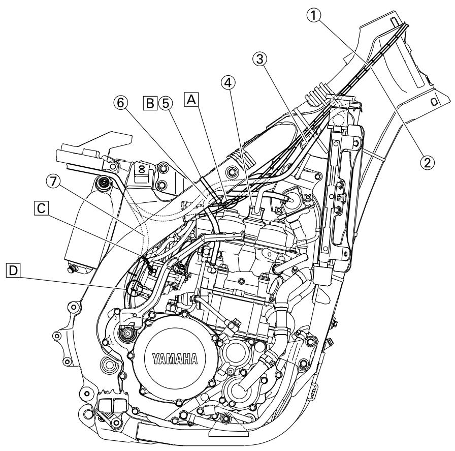
① Brake master cylinder
② Brake hose holder
③ Brake hose
A Install the brake hose so that its pipe portion directs as shown and lightly touches the projection on the brake caliper.
Pass the brake hose into the brake hose holders.
If the brake hose contacts the spring (rear shock absorber), correct its twist.
Install the brake hose so that its pipe portion directs as shown and lightly touches the projection on the brake master cylinder.
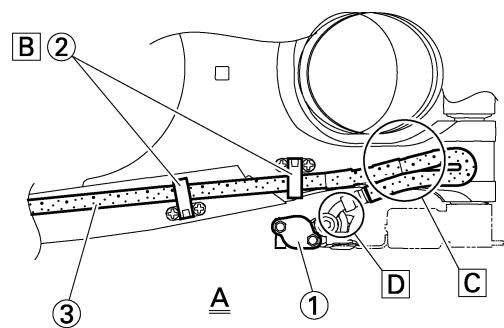
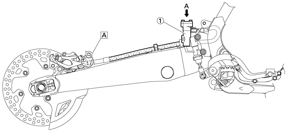
① Clamp
② Positive battery lead
③ Battery
Negative battery lead
⑤ Taillight coupler
⑥ CDI unit coupler (6-pin)
⑦ CDI unit coupler (3-pin)
⑧ CDI unit coupler (6-pin)
A Fasten the wire harness, negative battery lead and starter motor lead to the upper engine bracket (left side). Locate the clamp end facing toward the upper side of the frame with the tie end cut off on the inside of the frame.
B Fasten the wire harness, negative battery lead and starter motor lead to the upper engine bracket (left side). Locate the clamp end facing toward the upper side of the frame with the tie end cut off on the inside of the frame. Clamp the wire harness and negative lead at the marking.
Pass the starter motor lead through the hole in the relay holder.
Fit the cover securely.
Connect the wire harness to the starter relay.
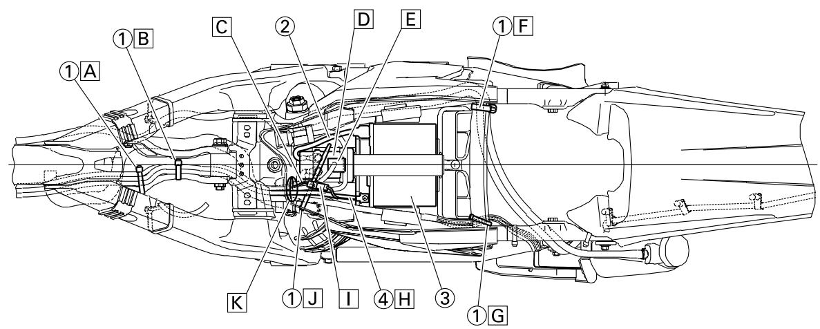
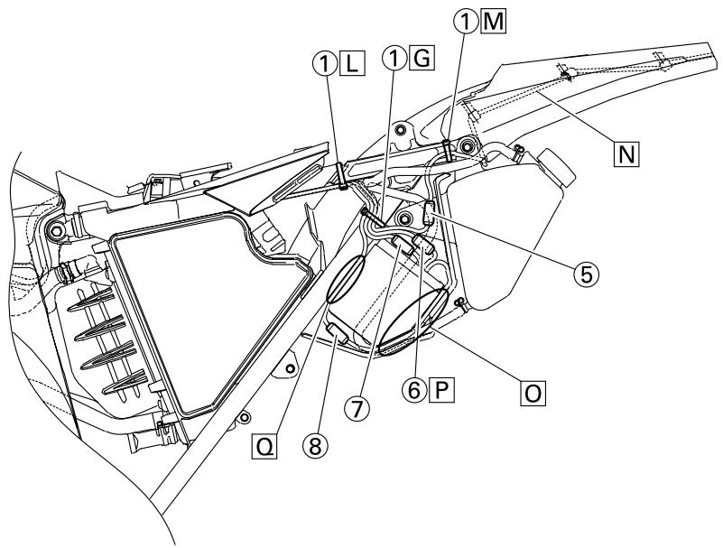
F Fasten the catch tank breather hose and catch tank hose to the rear frame. Clamp them close to where they are joined to the frame. Fasten the pipe tightly enough not to crush it. Locate the clamp end facing toward the rear of the frame with the tie end facing downward.
Fasten the (three) CDI unit leads and taillight lead to the rear frame. Locate the clamp end facing toward the upper side of the frame and cut off the tie end.
Connect the negative battery lead to the battery negative terminal.
Connect the negative battery lead to the wire harness.
Fasten the wire harness to the rear frame. Locate the clamp end facing toward the upper side of the frame and the tie end toward the inside of the frame. Clamp the wire harness at the marking.
Pass the wire harness, starter relay lead, starting circuit cut-off relay lead and negative battery lead through the hole in the relay holder.
Fasten the (three) CDI unit leads and taillight lead to the rear frame. Locate the clamp end facing toward the lower side of the frame and cut off the tie end.
M Fasten the taillight lead to the rear frame. Locate the clamp end facing toward the upper side of the frame and cut off the time end.
N Do not allow the taillight lead to slacken.
Locate the CDI unit lead between the CDI unit and rear fender.
Locate the CDI unit coupler in the clearance between the upper side of the CDI unit and lower side of the catch tank stay.
Locate the CDI unit lead between the CDI unit and rear frame.
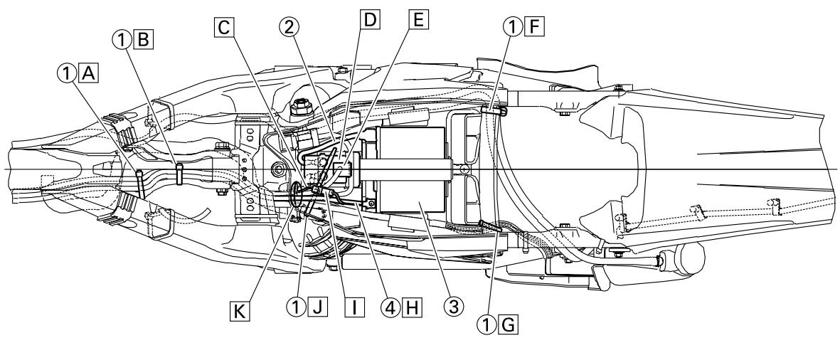

① Throttle cable
② Clamp
③ Brake hose
(4) Clutch cable
⑤ Hose guide
⑥ Main switch coupler
⑦ Wire harness
⑧ Headlight coupler
Hot starter cable
10 Multi-function display bracket
11 Main switch
Upper bracket
13 Clutch switch coupler
14 Engine stop switch coupler
15 Multi-function display coupler
16 Start switch coupler
⑰ Speed sensor coupler
18 Speed sensor lead
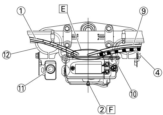
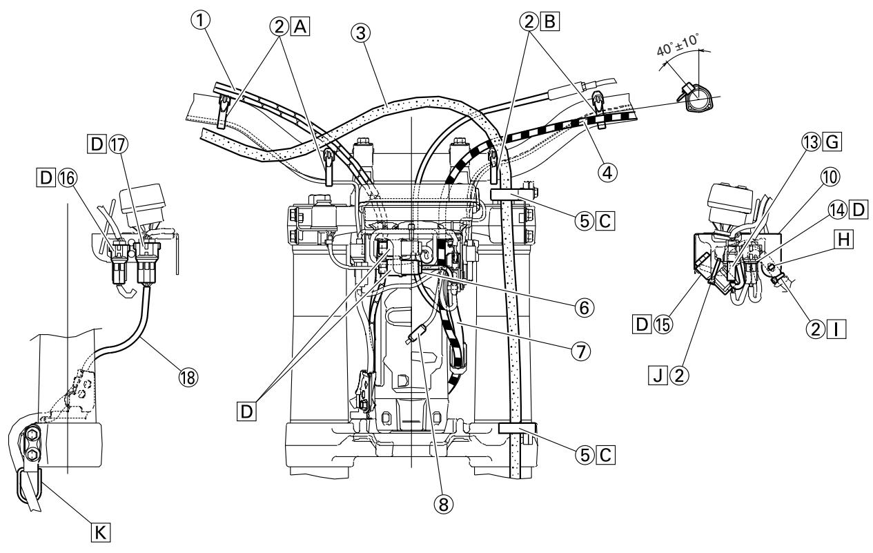
A Fasten the start switch lead to the handlebar with the plastic bands.
B Fasten the engine stop switch lead and clutch switch lead to the handlebar with the plastic bands.
Pass the brake hose through the hose guides.
Secure the coupler by inserting it into the multi-function display bracket.
Pass the throttle cables, clutch cable and hot starter cable between the upper bracket and multi-function display bracket.
Fasten the multi-function display leads to the bracket. Cut off the tie end.
Secure the coupler by pushing it into the hole in the multi-function display bracket.
Secure the wire harness clip by pushing it into the hole in the multi-function display bracket on the inside.
Fasten the wire harness to the multi-function display bracket. Cut off the tie end.
Fasten the main switch lead (wire harness side) to the multifunction display bracket. Locate the clamp end facing toward the lower side of the frame and cut off the tie end.
Pass the speed sensor lead through the guide on the outside of the front fork.


The following schedule is intended as a general guide to maintenance and lubrication. Bear in mind that such factors as weather, terrain, geographical location, and individual usage will alter the required maintenance and lubrication intervals. If you are a doubt as to what intervals to follow in maintaining and lubricating your machine, consult your Yamaha dealer.
| Item | After break-in | Every race | Every third (or 500 km) | Every fifth (or 1,000 km) | As required | Remarks |
| ENGINE OIL Replace | ● | ● | ||||
| VALVES Check the valve clearances | ● | ● | ● | ● | The engine must be cold. Check the valve seats and valve stems for wear. | |
| Inspect Replace | ||||||
| VALVE SPRINGS Inspect Replace | ● | ● | Check the free length and the tilt. | |||
| VALVE LIFTERS Inspect Replace | ● | ● | Check for scratches and wear. | |||
| CAMSHAFTS Inspect Replace | ● | ● | Inspect the camshaft surface. Inspect the decompression system. | |||
| CAMSHAFT SPROCKETS Inspect Replace | ● | ● | Check for wear on the teeth and for damage. | |||
| PISTON Inspect Clean Replace | ● | ● | Inspect crack Inspect carbon deposits and eliminate them. | |||
| PISTON RING Inspect Replace | ● | ● | Check ring end gap | |||
| PISTON PIN Inspect Replace | ● | ● | ||||
| CYLINDER HEAD Inspect and clean | ● | Inspect carbon deposits and eliminate them. Change gasket | ||||
| CYLINDER Inspect and clean Replace | ● | ● | Inspect score marks Inspect wear | |||
| CLUTCH Inspect and adjust Replace | ● | ● | ● | Inspect housing, friction plate, clutch plate and spring | ||
| TRANSMISSION Inspect Replace bearing | ● | ● | ||||
| SHIFT FORK, SHIFT CAM, GUIDE BAR Inspect | ● | Inspect wear | ||||
| ROTOR NUT | ||||||
| Retighten | ● | ● | ||||
| MUFFLER | ||||||
| Inspect and retighten | ● | ● | ||||
| Clean | ● | |||||
| Replace | ● | |||||
| CRANK | ||||||
| Inspect and clean | ● | ● | ||||
| CARBURETOR | ||||||
| Inspect, adjust and clean | ● | ● | ||||
| AIR INDUCTION SYSTEM | ||||||
| Inspect and clean | ● | ● | ● | ● | ||
| SPARK PLUG | ||||||
| Inspect and clean | ● | ● | ||||
| Replace | ● | |||||
| DRIVE CHAIN | Use chain lubeChain slack:48 ~ 58 mm (1.9 ~ 2.3 in) | |||||
| Lubricate, slack, alignment | ● | ● | ||||
| Replace | ● | |||||
| COOLING SYSTEM | ||||||
| Check coolant level and leakage | ● | ● | ||||
| Check radiator cap operation | ● | |||||
| Replace coolant | ● | |||||
| Inspect hoses | ● | Every two years | ||||
| OUTSIDE NUTS AND BOLTS | ||||||
| Retighten | ● | ● | Refer to "STARTING AND BREAK-IN" section in the CHAPTER 1. | |||
| AIR FILTER | ||||||
| Clean and lubricate | ● | ● | Use foam air-filter oil or equivalent oil | |||
| Replace | ● | |||||
| OIL FILTER | ||||||
| Replace | ● | ● | ||||
| OIL STRainer | ||||||
| Clean | ● | |||||
| FRAME | ||||||
| Clean and inspect | ● | ● | ||||
| FUEL TANK, COCK | ||||||
| Clean and inspect | ● | ● | ||||
| BRAKES | ||||||
| Adjust lever position and pedal height | ● | ● | ||||
| Lubricate pivot point | ● | ● | ||||
| Check brake disc surface | ● | ● | ||||
| Check fluid level and leakage | ● | ● | ||||
| Retighten brake disc bolts, caliper bolts, master cylinder bolts and union bolts | ● | ● | ||||
| Replace pads | ● | Every one year | ||||
| Replace brake fluid | ● | |||||
| FRONT FORKS | ||||||
| Inspect and adjust | ● | ● | Suspension oil "S1" | |||
| Replace oil | ● | ● | ● | |||
| Replace oil seal | ||||||
| FRONT FORK OIL SEAL AND DUST SEAL | Lithium base grease | |||||
| Clean and lube | ● | ● | ||||
| PROTECTOR GUIDE | ● | |||||
| Replace | ||||||
| REAR SHOCK ABSORBER | ||||||
| Inspect and adjust | ● | ● | (After rain ride) | Molybdenum disulfide grease | ||
| Lube | ● | |||||
| Retighten | ● | ● | ● | |||
| DRIVE CHAIN GUIDE AND ROLLERS | ||||||
| Inspect | ● | ● | ||||
| SWINGARM | Molybdenum disulfide grease | |||||
| Inspect, lube and retighten | ● | ● | ||||
| RELAY ARM, CONNECTING ROD | Molybdenum disulfide grease | |||||
| Inspect, lube and retighten | ● | ● | ||||
| SIDESTAND | ● | Lithium base grease | ||||
| Lubricate | ● | |||||
| STEERING HEAD | Lithium base grease | |||||
| Inspect free play and retighten | ● | ● | ● | |||
| Clean and lube | ● | |||||
| Replace bearing | ||||||
| TIRE, WHEELS | ||||||
| Inspect air pressure, wheel run-out, tire wear and spoke looseness | ● | ● | ||||
| Retighten sprocket bolt | ● | ● | ||||
| Inspect bearings | ● | |||||
| Replace bearings | ● | ● | Lithium base grease | |||
| Lubricate | ● | |||||
| THROTTLE, CONTROL CABLE | Yamaha cable lube or SAE 10W-30 motor oil | |||||
| Check routing and connection | ● | ● | ||||
| Lubricate | ● | ● | ||||
| HOT STARTER, CLUTCH LEVER | ● | |||||
| Inspect free play | ||||||
| BATTERY | ● | |||||
| Check terminal for looseness and corrosion | ● |
CONTROLES ET REGLAGES PERIODIQUES PROGRAMME D'ENTRETIEN
N.B.:
Before riding for break-in operation, practice, make sure the machine is in good operating condition.
Before using this machine, check the following points.
GENERAL INSPECTION AND MAINTENANCE
| Item | Routine | Page |
| Coolant | Check that coolant is filled up to the radiator cap. Check the cooling system for leakage. | P.3-35 ~ 41 |
| Fuel | Check that a fresh gasoline is filled in the fuel tank. Check the fuel line for leakage. | P.1-49 |
| Engine oil | Check that the oil level is correct. Check the crankcase and frame oil line for leakage. | P.3-51 ~ 59 |
| Gear shifter and clutch | Check that gears can be shifted correctly in order and that the clutch operates smoothly. | P.3-41 ~ 43 |
| Throttle grip/Housing | Check that the throttle grip operation and free play are correctly adjusted. Lubricate the throttle grip and housing, if necessary. | P.3-43 ~ 45 |
| Brakes | Check the play of front brake and effect of front and rear brake. | P.3-77 ~ 89 |
| Drive chain | Check drive chain slack and alignment. Check that the drive chain is lubricated properly. | P.3-91 ~ 95 |
| Wheels | Check for excessive wear and tire pressure. Check for loose spokes and have no excessive play. | P.3-111 ~ 113 |
| Steering | Check that the handlebar can be turned smoothly and have no excessive play. | P.3-113 ~ 117 |
| Front forks and rear shock absorber | Check that they operate smoothly and there is no oil leakage. | P.3-97 ~ 109 |
| Cables (wires) | Check that the clutch and throttle cables move smoothly. Check that they are not caught when the handlebars are turned or when the front forks travel up and down. | — |
| Exhaust pipe | Check that the exhaust pipe is tightly mounted and has no cracks. | P.3-27 ~ 31 |
| Rear wheel sprocket | Check that the rear wheel sprocket tightening bolt is not loose. | P.3-89 |
| Lubrication | Check for smooth operation. Lubricate if necessary. | P.3-119 |
| Bolts and nuts | Check the chassis and engine for loose bolts and nuts. | P.1-59 |
| Lead connectors | Check that the AC magneto, CDI unit, and ignition coil are connected tightly. | P.1-9 |
| Settings | Is the machine set suitably for the condition of the course and weather or by taking into account the results of test runs before riding? Are inspection and maintenance completely done? | P.4-1 ~ 40 |
CONTROLE ET ENTRETIEN AVANT UTILISATION
③ Side covers removal
④ Headlight removal
| Extent of removal | Order | Part name | Q'ty | Remarks |
| Preparation for removal | SEAT, FUEL TANK AND SIDE COVERS REMOVALTurn the fuel cock to "OFF". Disconnect the fuel hose. | |||
| 1↑2↑3↓4↑ | 1 | Seat | 1 | |
| 2 | Air scoop (left and right) | 2 | ||
| 3 | Bolt (fuel tank) | 2 | ||
| 4 | Fuel tank | 1 | ||
| 5 | Left side cover | 1 | Open the air filter case cover.Refer to "REMOVAL POINTS". | |
| 6 | Right side cover | 1 | ||
| 7 | Headlight coupler | 1 | ||
| 8 | Headlight | 1 |
MOTEUR
SELLE, RESERVOIR DE CARBURANT ET CACHES LATERAUX
REMOVAL POINTS Side cover
-
Remove:
-
Bolt (side cover)
- Right side cover ①
NOTE:
Draw the side cover backward to remove it because its claw 已 is inserted in the air filter case.
① Silencer removal
② Exhaust pipe removal
| Extent of removal | Order | Part name | Q'ty | Remarks |
| Preparation for removal | EXHAUST PIPE AND SILENCER REMOVAL | Refer to “SEAT, FUEL TANK AND SIDE COVERS” section. | ||
| Right side cover | ||||
| 1 | 2 | Bolt (silencer clamp) | 1 | Only loosening. |
| 3 | Bolt [silencer (front)] | 1 | ||
| 4 | Bolt [silencer (rear)] | 1 | ||
| 5 | Collar | 1 | ||
| 6 | Silencer | 1 | ||
| 7 | Silencer clamp | 1 | ||
| 8 | Nut (exhaust pipe) | 2 | ||
| 9 | Exhaust pipe | 1 | ||
| Gasket | 2 |
TUBE D'ECHAPPEMENT ET SILENCIEUX

Silencer and exhaust pipe
-
Inspect:
-
Gasket ① Damage → Replace.
CONTROLE
ASSEMBLY AND INSTALLATION
Silencer and exhaust pipe
-
Install:
-
Gasket New
- Exhaust pipe ①
- Nut (exhaust pipe) ②
20Nm (2.0m· kg,14 ft·lb)
ASSEMBLAGE ET MONTAGE
Do not remove the radiator cap ① drain bolt and hoses when the engine and radiator are hot. Scalding hot fluid and steam may be blown out under pressure, which could cause serious injury.
When the engine has cooled, place a thick towel over the radiator cap, slowly rotate the cap counterclockwise to the detent. This procedure allows any residual pressure to escape. When the hissing sound has stopped, press down on the cap while turning counterclockwise and remove it.
CAUTION:
Hard water or salt water is harmful to the engine parts. You may use distilled water, if you can't get soft water.
- Place the machine on a level place, and hold it in an upright position.
- Remove:
- Radiator cap
- Check:
Coolant level a
Coolant level low Add coolant.
① Radiator
CONTROLE DU NIVEAU DU LIQUIDE DE REFROIDISSEMENT
AVERTISSEMENT
Do not remove the radiator cap when the engine is hot.
CAUTION:
Take care so that coolant does not splash on painted surfaces. If it splashes, wash it away with water.
-
Place a container under the engine.
-
Remove:
-
Seat
- Left side cover
- Remove the catch tank hose from the catch tank and drain the tank of its coolant.
CHANGEMENT DU LIQUIDE DE REFROIDISSEMENT
AVERTISSEMENT
-
Remove:
-
Radiator cap
-
Drain the coolant completely.
-
Clean:
Cooling system Thoroughly flush the cooling system with clean tap water.
- Install:
Copper washer New
Coolant drain bolt
10 Nm (1.0 m·kg, 7.2 ft·lb)
Recommended coolant: High quality ethylene glycol anti-freeze containing anti-corrosion for aluminum engine
Coolant ① and water (soft water) ② mixing ratio: 50% /50% Coolant capacity: 0.99 L (0.87 Imp qt, 1.05 US qt)
CAUTION:
- Do not mix more than one type of ethylene glycol antifreeze containing corrosion inhibitors for aluminum engine.
- Do not use water containing impurities or oil.
Handling notes of coolant:
The coolant is harmful so it should be handled with special care.
WARNING
- When coolant splashes to your eye.
Thoroughly wash your eye with water and see your doctor. - When coolant splashes to your clothes.
Quickly wash it away with water and then with soap. - When coolant is swallowed.
Quickly make him vomit and take him to a doctor.
9. Install:
- Radiator cap
Start the engine and warm it up for a several minutes.
10. Check:
Coolant level
Coolant level low Add coolant.
8. Remplir:
- Radiateur
- Moteur
-
Inspect:
-
Seal (radiator cap) ①
- Valve and valve seat ② Crack/damage Replace. Exist fur deposits ③ Clean or replace.
CONTROLE DU BOUCHON DE RADIATEUR
-
Attach:
-
Radiator cap tester ① and adapter ②

Radiator cap tester: YU-24460-01/ 90890-01325
Radiator cap tester adapter: YU-33984/90890-01352
NOTE:
Apply water on the radiator cap seal.
③ Radiator cap
- Apply the specified pressure.

Radiator cap opening pressure: 110 kPa (1.1 kg/cm², 15.6 psi
CONTROLE DE LA PRESSION D'OUVERTURE DU BOUCHON DE RADIATEUR
-
Attach:
-
Radiator cap tester ① and adapter ②

Radiator cap tester: YU-24460-01/ 90890-01325
Radiator cap tester adapter: YU-33984/90890-01352
- Apply the specified pressure.

Standard pressure: 180 kPa (1.8 kg/cm², 25.6 psi)
NOTE:
- Do not apply pressure more than specified pressure.
- Radiator should be filled fully.
CONTROLE DU CIRCUIT DE REFROIDISSEMENT
Pressure
impossible to maintain the specified pressure for 10 seconds → Repair.
- Radiator ①
- Radiator hose joint ②
Coolant leakage Repair or replace.
- Radiator hose ③
Swelling Replace.
REGLAGE DE L'EMBRAYAGE
-
Check:
-
Clutch lever free play ④
Out of specification Adjust.

Clutch lever free play @: 8 ~ 13 mm
(0.31 ~ 0.51 in)
KÜHLSYSTEM KONTROLLIEREN
- Kontrollieren:
-
Adjust:
-
Clutch lever free play
Clutch lever free play adjustment steps:
- Loosen the locknuts ①.
- Adjust the free play by changing their tightening position.
- Tighten the locknuts.

Locknut: 7 Nm (0.7 m • kg, 5.1 ft • lb)
- Make minute adjustment on the lever side using the adjuster ②.
After adjustment, check proper operation of clutch lever.
N.B.:
THROTTLE CABLE ADJUSTMENT
-
Check:
-
Throttle grip free play ⑧ Out of specification Adjust.

Throttle grip free play @: 3 ~ 5 mm (0.12 ~ 0.20 in)
REGLAGE DU CABLE DES GAZ
Throttle grip free play
Throttle grip free play adjustment steps:
- Slide the adjuster cover.
- Loosen the locknut ①.
- Turn the adjuster ② until the specified free play is obtained.
- Tighten the locknut.

Locknut: 4 Nm (0.4 m • kg, 2.9 ft • lb)
NOTE:
Before adjusting the throttle cable free play, the engine idle speed should be adjusted.
WARNING
After adjusting the throttle cable free play, start the engine and turn the handlebar to right and left and make sure that the engine idling does not run faster.
-
Remove:
-
Cover (throttle cable cap) ①
Cover (grip cap) ②
Throttle grip cap ③ -
Apply:
Lithium soap base grease On the throttle cable end @.
- Install:
Throttle grip cap
- Screw (throttle grip cap)
4 Nm (0.4 m·kg, 2.9 ft·lb)
- Cover (grip cap)
- Cover (throttle cable cap)
GRAISSAGE DE L'ACCELERATI
Hot starter lever free play ④
3~6mm
(0.12 ~ 0.24 in)
- Adjust:
Hot starter lever free play
Hot starter lever free play adjustment steps:
- Loosen the locknut ①.
- Turn the adjuster ② until free play ④ is within the specified limits.
- Tighten the locknut.

Locknut:
4Nm
(0.4 m • kg, 2.9 ft • lb)
NOTE:
After adjustment, check proper operation of hot starter.
REGLAGE DU LEVIER DEMARRAGE A CHAUD
Proper air filter maintenance is the biggest key to preventing premature engine wear and damage.
CAUTION:
Never run the engine without the air filter element in place; this would allow dirt and dust to enter the engine and cause rapid wear and possible engine damage.
NETTOYAGE DU FILTRE A AIR
N.B.:
- Open the air filter case cover ①
NOTE:
Loosen the quick screw ② and pull on it to open the air filter case cover.
Air filter element ①
Air filter element Clean them with solvent.
NOTE:
After cleaning, remove the remaining solvent by squeezing the element.
CAUTION:
- Do not twist the element when squeezing the element.
-
Leaving too much of solvent in the element may result in poor starting.
-
Nettoyer:
-
Elément de filtré à air Nettoyer à l'aide d'un solvant.
N.B.:
-
Apply:
-
Foam-air-filter oil or equivalent oil to the element
NOTE:
- Squeeze out the excess oil. Element should be wet but not dripping.
-
Wipe off the oil left on the element surface using a clean dry cloth. (Excess oil in the element may adversely affect engine starting.)
-
Controller:
-
Elément de filtré à air Endommagement → Remplacer.
-
Appliquer:
- Align the projection ④ on filter guide with the hole ⑥ in air filter element.
-
Apply the lithium soap base grease on the matching surface © on air filter element.
-
Monter:
-
Guide du filtré ①
N.B.:
Air filter element ①
NOTE:
Align the projection ⑧ on filter guide with the hole ⑥ in air filter case.
Hook the binder ① so that it contacts the filter guide projections ⑧.
- Accrocher:
Fixation ①
N.B.:
-
Start the engine, warm it up for several minutes, and then turn off the engine and wait for five minutes.
-
Place the machine on a level place and hold it up on upright position by placing the suitable stand under the engine.
-
Inspect:
Oil level
Oil should be up to the full level in the check window ① Level check window is not full.
Add 0.2 L (0.18 Imp qt, 0.21 US qt) of oil.
(For USA and CDN)

Recommended oil:
Yamalube 4,
SAE10W30 or
SAE 20W40
Yamalube 4-R,
SAE10W50
API service SG type or
higher, JASO standard
MA
CAUTION:
- Do not add any chemical additives. Engine oil also lubricates the clutch and additives could cause clutch slippage.
- Do not allow foreign material to enter the crankcase.
CONTROLE DU NIVEAU D'HUILMEOTEUR
(Except for USA and CDN)

Recommended oil:
SAE10W30,
SAE10W40,
SAE15W40,
SAE20W40 or
SAE20W50
API service SG ty
higher, JASO sta
MA
CAUTION:
- Do not add any chemical additives or use oils with a grade of CD ⑧ or higher.
- Do not use oils labeled "ENERGY CONSERVING II" ⑤ or higher. Engine oil also lubricates the clutch and additives could cause clutch slippage.
-
Do not allow foreign materials to enter the crankcase.
-
Install:
Oil tank cap - Start the engine and let it warm up for several minutes.
- Turn off the engine and inspect the oil level once again.
NOTE:
Wait a few minutes until the oil settles before inspecting the oil level.
(sauf USA et CDN)

Huile recommandée:
SAE10W30, SAE10W40,
SAE15W40, SAE20W40
ou SAE20W50
API Service de type SG
et au-delà/JASO MA
ATTENTION:
ENGINE OIL REPLACEMENT
- Start the engine and warm it up for several minutes, and then turn off the engine and wait for five minute.
- Place the machine on a level place and hold it on upright position by placing the suitable stand under the engine.
- Place a suitable container under the engine.
CHANGEMENT DE L'HUILMOTEUR
Engine guard ①
- Bolt (oil tank) ②
- Washer ③
- Oil filler cap ④
- Oil tank drain bolt ⑤
- Crankcase oil drain bolt ⑥
- Oil filter element drain bolt ⑦ Drain the crankcase and oil tank of its oil.
4. Déposer:
- Oil hose clamp ①
- Bolt (oil hose)
- Oil hose ②
- Oil strainer ③
6. Inspect:
Oil strainer Clogged Blow.
- If the oil filter is to be replaced during this oil change, remove the following parts and reinstall them.
Replacement steps:
- Remove the oil filter element cover ① and oil filter element ②.
- Check the O-rings ③ , if cracked or damaged, replace them with a new one.
- Install the oil filter element and oil filter element cover.

Oil filter element cover: 10 Nm (1.0 m • kg, 7.2 ft • lb)
5. Déposer:
-
Install:
-
O-ring ①
- Oil strainer ②
9Nm (0.9m· kg,6.5ft· lb)
- Oil hose
- Bolt (oil hose)
8Nm (0.8m· kg,5.8ft· lb)
Oil hose clamp
2Nm (0.2m· kg,1.4ft· lb)
- Install:
Copper washer New
- Oil filter element drain bolt
10Nm(1.0m·kg,7.2ft·lb)
- Crankcase oil drain bolt
20Nm (2.0m· kg,14ft· lb) -
Oil tank drain bolt
18Nm (1.8 m · kg, 13 ft · lb)
Engine guard
7Nm (0.7m· kg,5.1ft· lb) -
Fill:
Engine oil

Oil quantity:
Periodic oil change:
1.1 L
(0.97 Imp qt,
1.16 US qt)
With oil filter
replacement:
1.2 L
(1.06 Imp qt,
1.27 US qt)
Total amount:
1.4 L
(1.23 Imp qt,
1.48 US qt)
- Check:
Oil leakage
- Install:
Oil filler cap
- Washer (oil tank)
- Bolt (oil tank)
7Nm (0.7m· kg,5.1 ft·lb)
-
Check:
-
Engine oil level
-
Monter:
-
Joint torque ① New
- Crépine à huile ②
9Nm (0,9m· kg,6,5ft· lb)
- Slightly loosen the oil pressure check bolt ①.
- Start the engine and keep it idling until oil starts to seep from the oil pressure check bolt. If no oil comes out after one minute, turn the engine off so it will not seize.
- Check oil passages and oil pump for damage or leakage.
- Start the engine after solving the problem(s) and recheck the oil pressure.
- Tighten the oil pressure check bolt.

Oil pressure check bolt: 10 Nm (1.0 m • kg, 7.2 ft • lb)
CONTROLE DE LA PRESSION D'HUIL
ENGINE IDLING SPEED ADJUSTMENT
-
Start the engine and thoroughly warm it up.
-
Adjust:
-
Engine idling speed
Adjustment steps:
- Turn the throttle stop screw ① until the specified engine idling speed.
NOTE:
Using a digital engine tachometer for idle speed adjustment, detect the engine idling speed by bringing the sensing element ⑥ of the engine tachometer close to the ignition coil ②
To increase idle speed Turn the throttle stop screw ① in ④
To decrease idle speed Turn the throttle stop screw ① out ⑥

Engine idling speed: 1,750 ~ 1,950 r/min
VALVE CLEARANCE INSPECTION AND ADJUSTMENT
NOTE:
This section is intended for those who have basic knowledge and skill concerning the servicing of Yamaha motorcycles (e.g., Yamaha dealers, service engineers, etc.) Those who have little knowledge and skill concerning servicing are requested not to undertake inspection, adjustment, disassembly, or reassembly only by reference to this manual. It may lead to servicing trouble and mechanical damage.
NOTE:
- The valve clearance should be adjusted when the engine is cool to the touch.
- The piston must be at Top Dead Center (T.D.C.) on compression stroke to check or adjust the valve clearance.
1. Remove:
- Seat
- Fuel tank Refer to "SEAT, FUEL TANK AND SIDE COVERS" section.
2. Drain:
Coolant Refer to "COOLANT REPLACEMENT" section.
3. Remove:
- Right radiator Refer to "RADIATOR" section in the CHAPTER 5.
- Carburetor Refer to "CARBURETOR" section in the CHAPTER 5.
Spark plug - Upper engine bracket
- Cylinder head cover Refer to "CAMSHAFTS" section in the CHAPTER 5.
INSPECTION ET REGLAGE DU JEU AUX SOUPAPES
N.B.:
- Timing mark accessing screw ①
- Crankshaft end accessing screw ②
- O-ring
4. Déposer:
Valve clearance (cold):
Intake valve: 0.10 ~ 0.15 mm (0.0039 ~ 0.0059 in) Exhaust valve: 0.17 ~ 0.22 mm (0.0067 ~ 0.0087 in)
Checking steps:
- Turn the crankshaft counterclockwise with a wrench.
- Align the T.D.C. mark ⑧ on the rotor with the align mark ⑥ on the crankcase cover when piston is at T.D.C. on compression stroke.
NOTE:
In order to be sure that the piston is at Top Dead Center, the punch mark ⑥ on the exhaust camshaft and the punch mark ④ on the intake camshaft must align with the cylinder head surface, as shown in the illustration.
- Measure the valve clearance ⑥ using a feeler gauge ①.
NOTE:
Record the measured reading if the clearance is incorrect.
5. Controller:
- Remove the camshaft (intake and exhaust).
Refer to "CAMSHAFTS" section in the CHAPTER 5.
- Remove the valve lifters ① and the pads ②.
NOTE:
- Place a rag in the timing chain space to prevent pads from falling into the crankcase.
-
Identity each valve lifter and pad position very carefully so that they can be reinstalled in their original place.
-
Select the proper pad using the pad selecting table.
| Pad range | Pad Availability: 25 increments | |
| No. 120 ~ No. 240 | 1.20 mm ~ 2.40 mm | Pads are available in 0.05 mm increments |
NOTE:
The thickness ⑧ of each pad is indicated in hundredths of millimeters on the pad upper surface.
- Round off the last digit of the installed pad number to the nearest increment.
| Last digit of pad number | Rounded value |
| 0, 1 or 2 | 0 |
| 4, 5 or 6 | 5 |
| 8 or 9 | 10 |
6. Régler:
- Jeu aux soupapes
Étapés du réglage:
Pads can only be selected in 0.05 mm increments.
- Locate the rounded-off value and the measured valve clearance in the chart "PAD SELECTION TABLE". The field where these two coordinates intersect shows the new pad number to use.
NOTE:
Use the new pad number only as a guide when verifying the valve clearance adjustment.
Install the new pads ③ and the valve lifters ④
NOTE:
- Apply the engine oil on the valve lifters.
- Apply the molybdenum disulfide oil on the valve stem ends.
- Valve lifter must turn smoothly when rotated with a finger.
- Be careful to reinstall valve lifters and pads in their original place.
- Install the camshafts (exhaust and intake). Refer to "CAM-SHAFTS" section in the CHAPTER 5.
EXAMPLE:
- Be sure the exhaust pipe and silencer are cool before cleaning the spark arrester.
-
Do not start the engine when cleaning the exhaust system.
-
Remove:
-
Screw (silencer cap) ①
- Remove:
-
Bolt (spark arrester) ①
-
Remove:
Tail pipe ①
- Gasket (tail pipe) ②
- Spark arrester ③
Pull the spark arrester out of the silencer.
-
Gasket (spark arrester) ④
-
Clean:
-
Spark arrester
Tap the spark arrester lightly, then use a wire brush to remove any carbon deposits.
-
Install:
-
Gasket (spark arrester)
- Spark arrester
Insert the spark arrester into the silencer and align the bolt holes.
- Gasket (tail pipe)
- Bolt (spark arrester)
7Nm (0.7m· kg,5.1ft· lb)
NETTOYAGE DU PARE-ETINCELLES (USA)
WARNING
First tighten the two screws ⑧ located horizontally apart, and then tighten the others.
-
Monter:
-
Capuchon de silencieux
5Nm(0,5m·kg,3,6ft·lb)
N.B.:
Bleed the brake system if:
- The system has been disassembled.
- A brake hose has been loosened or removed.
- The brake fluid is very low.
- The brake operation is faulty.
A dangerous loss of braking performance may occur if the brake system is not properly bled.
-
Remove:
-
Brake master cylinder cap
Diaphragm - Reservoir float (front brake)
-
Protector (rear brake)
-
Bleed:
-
Brake fluid
A Front
Rear
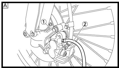
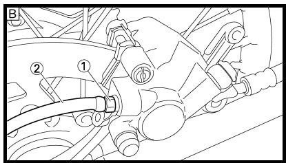
Air bleeding steps:
a. Add proper brake fluid to the reservoir.
b. Install the diaphragm. Be careful not to spill any fluid or allow the reservoir to overflow.
c. Connect the clear plastic tube ② tightly to the caliper bleed screw ①.
d. Place the other end of the tube into a container.
e. Slowly apply the brake lever or pedal several times.
f. Pull the lever in or push down on the pedal. Hold the lever or pedal in position.
g. Loosen the bleed screw and allow the lever or pedal to travel towards its limit.
h. Tighten the bleed screw when the lever or pedal limit has been reached; then release the lever or pedal.

Bleed screw:
6Nm
(0.6 m • kg, 4.3 ft • lb)
i. Repeat steps (e) to (h) until of the air bubbles have been removed from the system.
CHÄSSIS
PURGE D'AIR DU CIRCUIT DE FREINAGE
AVERTISSEMENT
If bleeding is difficult, it may be necessary to let the brake fluid system stabilize for a few hours. Repeat the bleeding procedure when the tiny bubbles in the system have disappeared.
j. Add brake fluid to the level line on the reservoir.
WARNING
Check the operation of the brake after bleeding the brake system.
3. Install:
- Protector (rear brake)
- Reservoir float (front brake)
- Diaphragm
- Brake master cylinder cap
N.B.:
- Brake lever position @
| Brake lever position @: | |
| Standard position | Extent of adjustment |
| 95 mm (3.74 in) | 76 ~ 97 mm (2.99 ~ 3.82 in) |
2. Remove:
- Brake lever cover
3. Adjust:
- Brake lever position
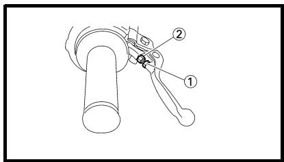
Brake lever position adjustment steps:
- Loosen the locknut ①.
- Turn the adjusting bolt ② until the lever position ⑧ is within specified position.
- Tighten the locknut.

Locknut:
5Nm
(0.5 m • kg, 3.6 ft • lb)
CAUTION:
Be sure to tighten the locknut, as it will cause poor brake performance.
4. Install:
- Brake lever cover
-
Adjust:
-
Brake pedal height
Pedal height adjustment steps:
- Loosen the locknut ①.
- Turn the adjusting nut ② until the pedal height 当 is within specified height.
- Tighten the locknut.
WARNING
- Adjust the pedal height between the maximum A and the minimum B as shown. (In this adjustment, the bolt ③ end ⑥ should protrude out of the threaded portion ④ but not be less than 2 mm (0.08 in) ⑤ away from the brake pedal ⑤).
- After the pedal height adjustment, make sure that the rear brake does not drag.
REGLAGE DU FREIN ARRIERE
-
Inspect:
-
Brake pad thickness ⑧ Out of specification Replace as a set.

Brake pad thickness: 4.4 mm (0.17 in)
CONTROLE ET REMPLACEMENT DES PLAQUETTES DE FREIN AVANT
Brake pad replacement steps:
-
Remove the pad pin plug ①.
-
Remplacer:
-
Plaquette de frein
- Loosen the pad pin ②.
- Remove the brake caliper ③ from the front fork.
- Remove the pad pin and brake pads ④.
- Connect the transparent hose ⑤ to the bleed screw ⑥ and place the suitable container under its end.
- Loosen the bleed screw and push the brake caliper piston in.
CAUTION:
Do not reuse the drained brake fluid.
- Tighten the bleed screw.

Bleed screw: 6 Nm (0.6 m • kg, 4.3 ft • lb)
Install the brake pads ⑦ and pad pin.
NOTE:
Install the brake pads with their projections 已 into the brake caliper recesses 已 .
- Temporarily tighten the pad pin at this point.
Install the brake caliper ⑧ and tighten the pad pin ⑨

Bolt (brake caliper): 23 Nm (2.3 m • kg, 17 ft • lb)
Pad pin: 18 Nm (1.8 m • kg, 13 ft • lb)
Install the pad pin plug ⑩.

Pad pin plug: 3 Nm (0.3 m • kg, 2.2 ft • lb)
- Brake fluid level Refer to "BRAKE FLUID LEVEL INSPECTION" section.
3. Controller:
-
Inspect:
-
Brake pad thickness @ Out of specification Replace as a set.

Brake pad thickness: 6.4 mm (0.25 in)
CONTROLE ET REMPLACEMENT DES PLAQUETTES DE FREIN ARRIERE
Brake pad replacement steps:
- Remove the protector ① and pad pin plug ②.
- Loosen the pad pin ③.
- Remove the rear wheel ④ and brake caliper ⑤ .
Refer to "FRONT WHEEL AND REAR WHEEL" section in the CHAPTER 6.
- Remove the pad pin ⑥ and brake pads ⑦.
- Connect the transparent hose ⑧ to the bleed screw ⑨ and place the suitable container under its end.
- Loosen the bleed screw and push the brake caliper piston in.
CAUTION:
Do not reuse the drained brake fluid.
- Tighten the bleed screw.

Bleed screw: 6 Nm (0.6 m • kg, 4.3 ft • lb)
-
Remplacer:
-
Plaquette de frein
Install the brake pad ⑩ and pad pin ⑪
NOTE:
- Install the brake pads with their projections ④ into the brake caliper recesses ⑥ .
- Temporarily tighten the pad pin at this point.
Install the brake caliper ⑫ and rear wheel ⑬
Refer to "FRONT WHEEL AND REAR WHEEL" section in the CHAPTER 6.
- Tighten the pad pin ⑭.

Pad pin:
18Nm
(1.8 m • kg, 13 ft • lb)
Install the pad pin plug 15 and protector 16.

Pad pin plug:
3Nm
(0.3 m • kg, 2.2 ft • lb)
Bolt (protector):
7Nm
(0.7 m • kg, 5.1 ft • lb)
3. Inspect:
- Brake fluid level
Refer to "BRAKE FLUID LEVEL INSPECTION" section.
4. Check:
- Brake pedal operation
A soft or spongy feeling Bleed brake system.
Refer to "BRAKE SYSTEM AIR BLEEDING" section.
Boulon (protection):
7Nm
(0,7m· kg,5,1ft· lb)
3. Controller:
Refer to "REAR BRAKE PAD INSPECTION AND REPLACEMENT" section.
2. Inspect:
- Rear brake pad insulator ① Damage Replace.
CONTROLE DE L'ISOLANT DE PLAQUETTE DE FREIN ARRIERE
1. Déposer:
- Plaquette de frein
Se reporter à la section “CON- TROLE ET REMPLACEMENT DES PLAQUETTES DE FREIN ARRIERE”.
2. Controller:
-
Place the brake master cylinder so that its top is in a horizontal position.
-
Inspect:
-
Brake fluid level Fluid at lower level Fill up.
@ Lower level
A Front
Rear

Recommended brake fluid: DOT #4
WARNING
- Use only designated quality brake fluid to avoid poor brake performance.
- Refill with same type and brand of brake fluid; mixing fluids could result in poor brake performance.
- Be sure that water or other contaminants do not enter master cylinder when refilling.
- Clean up spilled fluid immediately to avoid erosion of painted surfaces or plastic parts.
CONTROLE DU NIVEAU DU LIQUIDE DE FREIN
-
Inspect:
-
Sprocket teeth (a) Excessive wear Replace.
NOTE:
Replace the drive sprocket, rear wheel sprocket and drive chain as a set.
CONTROLE DES PIGNONS
-
Controller:
-
Dents de pignon @ Usure excessive Remplacer.
N.B.:
- While measuring the drive chain length, push down on the drive chain to increase its tension.
Measure the length between drive chain roller ① and ⑯ as shown. -
Perform this measurement at two or three different places.
-
Remove:
-
Drive chain ①
NOTE:
Remove the drive chain using a drive chain cutter ②.
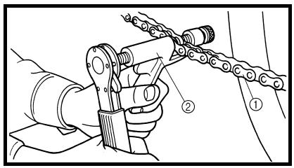
-
Clean:
-
Drive chain
Brush off as much dirt as possible. Then clean the drive chain using the chain cleaner.
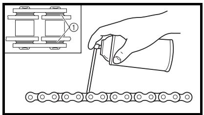
CAUTION:
This machine has a drive chain with small rubber O-rings ① between the side plates. Steam cleaning, high-pressure washes, certain solvent and kerosene can damage these O-rings.
CONTROLE DE LA CHAINE DE TRANSMISSION
- O-ring ②
- Drive chain ③
NOTE:
When installing the drive chain, apply the lithium soap base grease on the chain joint and O-rings.
7. Install:
- Link plate ④ New
NOTE:
- Press the link plate onto the chain joint using a drive chain riveter ⑤.
- Rivet the end of the chain joint using a drive chain riveter.
After riveting the chain joint, make sure its movement is smooth.
8. Lubricate:
Drive chain

Drive chain lubricant: SAE 10W-30 motor oil or suitable chain lubricants
6. Monter:
- Elevate the rear wheel by placing the suitable stand under the engine.
2. Check:
- Drive chain slack (a)
Above the seal guard installation bolt.
Out of specification Adjust.

Drive chain slack: 48 ~ 58 mm (1.9 ~ 2.3 in)
NOTE:
Before checking and/or adjusting, rotate the rear wheel through several revolutions and check the slack several times to find the tightest point. Check and/or adjust the drive chain slack with the rear wheel in this "tight chain" position.
REGLAGE DE LA TENSION DE LA CHAINDE TRANSMISSION
Drive chain slack adjustment steps:
- Loosen the axle nut ① and locknuts ②.
- Adjust the drive chain slack by turning the adjusters ③.
To tighten Turn the adjuster ③ counterclockwise.
To loosen Turn the adjuster ③ clockwise and push wheel forward.
- Turn each adjuster exactly the same amount to maintain correct axle alignment. (There are marks ⑧ on each side of the drive chain puller alignment.)
NOTE:
Turn the adjuster so that the drive chain is in line with the sprocket, as viewed from the rear.
CAUTION:
Too small drive chain slack will overload the engine and other vital parts; keep the slack within the specified limits.
- Tighten the axle nut while pushing down the drive chain.

Axle nut: 125 Nm (12.5 m • kg, 90 ft • lb)
- Tighten the locknuts.

Locknut: 19 Nm (1.9 m • kg, 13 ft • lb)
3. Régler:
- Front fork smooth action
- Operate the front brake and stroke the front fork.
- Unsmooth action/oil leakage Repair or replace.
CONTROLE DE LA FOURCHE
1. Contrôler:
FRONT FORK OIL SEAL AND DUST SEAL CLEANING
1. Remove:
- Protector
- Dust seal ①
NOTE:
Use a thin screw driver, and be careful not to damage the inner fork tube and dust seal.
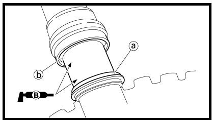
2. Clean:
- Dust seal (a)
- Oil seal (5)
NOTE:
- Clean the dust seal and oil seal after every run.
- Apply the lithium soap base grease on the inner tube.
NETTOYAGE DE LA BAGUE D'ETANCHEITE ET DU JOINT ANTIPOUSSIÈRE DE FOURCHE
1. Déposer:
Protection
- Joint antipoussière (1)
N.B.:
If the front fork initial movement feels stiff during a run, relieve the front fork internal pressure.
-
Elevate the front wheel by placing a suitable stand under the engine.
-
Remove the air bleed screw ① and release the internal pressure from the front fork.
3. Install:
Air bleed screw 1 Nm (0.1 m · kg, 0.7 ft · lb)
REDUCTION DE LA PRESSION INTERNE DE LA FOURCHE
N.B.:
-
Adjust:
-
Rebound damping force By turning the adjuster ①.
Stiffer ⑧ Increase the rebound damping force. (Turn the adjuster ① in.)
Softer ⑥ Decrease the rebound damping force. (Turn the adjuster ① out.)

Extent of adjustment:
Maximum
Minimum
Fully turned in position
20 clicks out from maximum position)
- STANDARD POSITION: This is the position which is back by the specific number of clicks from the fully turned-in position.

Standard position: 9 clicks out
CAUTION:
Do not force the adjuster past the minimum or maximum extent of adjustment. The adjuster may be damaged.
WARNING
Always adjust each front fork to the same setting. Uneven adjustment can cause poor handling and loss of stability.
REGLAGE DE LA FORCE D'AMORTISSEMENT A LA DETENTE DE LA FOURCHE
- Remove:
Rubber cap - Adjust:
- Compression damping force By turning the adjuster ①.
Stiffer ⑧ Increase the compression damping force. (Turn the adjuster ① in.)
Softer ⑥ Decrease the compression damping force. (Turn the adjuster ① out.)

Extent of adjustment:
Maximum
Minimum
Fully turned in position
20 clicks out (from maximum position)
STANDARD POSITION:
This is the position which is back by the specific number of clicks from the fully turned-in position.

Standard position: 10 clicks out * 11 clicks out
- Except for USA and CDN
CAUTION:
Do not force the adjuster past the minimum or maximum extent of adjustment. The adjuster may be damaged.
WARNING
Always adjust each front fork to the same setting. Uneven adjustment can cause poor handling and loss of stability.
- Install:
Rubber cap
REGLAGE DE LA FORCE
D'AMORTISSEMENT A LA COMPRESSION DE LA FOURCHE
-
Inspect:
-
Swingarm smooth action Abnormal noise/unsmooth action Grease the pivoting points or repair the pivoting points. Damage/oil leakage Replace.
REAR SHOCK ABSORBER
SPRING PRELOAD ADJUSTMENT
- Elevate the rear wheel by placing the suitable stand under the engine.
- Remove:
Rear frame - Loosen:
- Locknut ①
- Adjust:
Spring preload By turning the adjuster ②
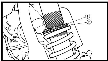
Stiffer Increase the spring preload. (Turn the adjuster ② in.)
Softer Decrease the spring preload. (Turn the adjuster ② out.)
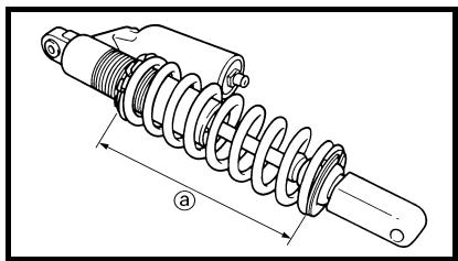
| Spring length (installed) a: | |
| Standard length | Extent of adjustment |
| 249 mm (9.80 in) * 248.5 mm (9.78 in) ** 245.0 mm (9.65 in) | 238.5 ~ 258.5 mm (9.39 ~ 10.18 in) |
- For EUROPE
** For AUS, NZ and ZA
NOTE:
- Be sure to remove all dirt and mud from around the locknut and adjuster before adjustment.
- The length of the spring (installed) changes 1.5 mm (0.06 in) per turn of the adjuster.
CAUTION:
Never attempt to turn the adjuster beyond the maximum or minimum setting.
- Tighten:
- Locknut
- Install:
Rear frame (upper)
32Nm(3.2m·kg,23ft·lb) - Rear frame (lower)
29Nm(2.9m·kg,21ft·lb)
CONTROLE DE L'AMORTISSEUR ARRIÈRE
-
Adjust:
-
Rebound damping force By turning the adjuster ①.
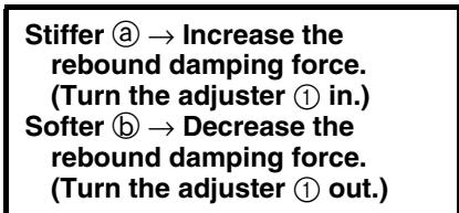
| Extent of adjustment: | |
| Maximum | Minimum |
| Fully turned in position | 20 clicks out (from maximum position) |
REGLAGE DE LA FORCE D'AMORTISSEMENT A LA DETENTE DE L'AMORTISSEUR ARRIERE
This is the position which is back by the specific number of clicks from the fully turned-in position. (Which align the punch mark ⑧ on the adjuster with the punch mark ⑥ on the bracket.)

Standard position: About 11 clicks out
CAUTION:
Do not force the adjuster past the minimum or maximum extent of adjustment. The adjuster may be damaged.
- POSITION STANDARD:
-
Adjust:
-
Low compression damping force By turning the adjuster ① .
| Stiffer ⑧ → Increase the low compression damping force. (Turn the adjuster ① in.) |
| Softer ⑤ → Decrease the low compression damping force. (Turn the adjuster ① out.) |
| Extent of adjustment: | |
| Maximum | Minimum |
| Fully turned in position | 20 clicks out (from maximum position) |
REGLAGE DE LA FORCE D'AMORTISSEMENT A LA COMPRESSION BASSE DE L'AMORTISSEUR ARRIERE
This is the position which is back by the specific number of clicks from the fully turned-in position. (Which align the punch mark ⑧ on the adjuster with the punch mark ⑥ on the high compression damping adjuster.)

Standard position: About 12 clicks out * About 13 clicks out
- For AUS, NZ and ZA
CAUTION:
Do not force the adjuster past the minimum or maximum extent of adjustment. The adjuster may be damaged.
- POSITION STANDARD:
-
Adjust:
-
High compression damping force By turning the adjuster ① .
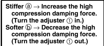
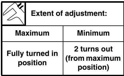
REGLAGE DE LA FORCE D'AMORTISSEMENT A LA COMPRESSION HAUTE DE L'AMORTISSEUR ARRIERE
This is the position which is back by the specific number of turns from the fully turned-in position. (Which align the punch mark ⑧ on the adjuster with the punch mark ⑥ on the adjuster body.)

Standard position: About 1-1/8 turns out * About 1-1/4 turns out
- For EUROPE
CAUTION:
Do not force the adjuster past the minimum or maximum extent of adjustment. The adjuster may be damaged.
- POSITION STANDARD:
-
Measure:
-
Tire pressure Out of specification Adjust.

Standard tire pressure: 100 kPa (1.0 kgf/cm², 15 psi)
NOTE:
- Check the tire while it is cold.
- Loose bead stoppers allow the tire to slip off its position on the rim when the tire pressure is low.
- A tilted tire valve stem indicates that the tire slips off its position on the rim.
- If the tire valve stem is found tilted, the tire is considered to be slipping off its position. Correct the tire position.
CONTROLE DE LA PRESSION DES PNEUS
-
Mesurer:
-
Pression des pneus Hors specifications Ajuster.

Pression des pneus standard: 100 kPa (1,0 kgf/cm², 15 psi)
N.B.:
3Nm(0.3m·kg,2.2ft·lb)
NOTE:
Be sure to retighten these spokes before and after break-in. After a practice check spokes for looseness.
CONTROLE ET SERRAGE DES RAYONS
-
Controller:
-
Rayons ①
Déformation/endommagement → Remplacer.
Rayon desseré → Resserrer. -
Serrer:
Rayons
3Nm(0,3m·kg,2,2ft·lb)
N.B.:
-
Inspect:
-
Wheel runout Elevate the wheel and turn it. Abnormal runout Replace.
CONTROLE DES ROUES
- Controller:
- Inspect:
- Bearing free play Exist play Replace.
EC36U013
STEERING HEAD INSPECTION AND ADJUSTMENT
- Elevate the front wheel by placing a suitable stand under the engine.
- Check:
- Steering stem
- Grasp the bottom of the forks and gently rock the fork assembly back and forth.
- Free play Adjust steering head.
- Check:
- Steering smooth action
- Turn the handlebar lock to lock.
- Unsmooth action Adjust steering ring nut.
- Adjust:
- Steering ring nut
| Steering ring nut adjustment steps: ·Remove the headlight. ·Remove the handlebar and upper bracket. ·Loosen the steering ring nut ① using the steering nut wrench ②. | |
| Steering nut wrench: YU-33975/90890-01403 | |
| ·Tighten the steering ring nut ③ using steering nut wrench ④. NOTE: ·Apply the lithium soap base grease on the thread of the steering stem. ·Set the torque wrench to the steering nut wrench so that they form a right angle. | |
| Steering nut wrench: YU-33975/90890-01403 | |
| Steering ring nut (initial tightening): 38 Nm (3.8 m • kg, 27 ft • lb) | |
Hakenschlüssel: YU-33975/90890-01403
- Loosen the steering ring nut one turn.
- Retighten the steering ring nut using the steering nut wrench.
WARNING
Avoid over-tightening.

Steering ring nut (final tightening): 7 Nm (0.7m kg,5.1ft lb)
- Check the steering stem by turning it lock to lock. If there is any binding, remove the steering stem assembly and inspect the steering bearings.
Install the washer ⑤ collar ⑥ upper bracket ⑦ ,washer ⑧ steering stem nut ⑨ ,handlebar ⑩ , handlebar upper holder ⑪ and headlight ⑫
NOTE:
Install the collar ⑥ with the larger inside diameter facing downwards.
- The handlebar upper holder should be installed with the punched mark @ forward.
- Install the handlebar so that the marks ⑥ are in place on both sides.
Install the handlebar so that the projection of the handlebar upper holder is positioned at the mark on the handlebar as shown.
- Insert the end of the fuel breather hose into the hole in the steering stem.
CAUTION:
First tighten the bolts on the front side of the handlebar upper holder, and then tighten the bolts on the rear side.
Headlight (left and right): 7 Nm
(0.7 m • kg, 5.1 ft • lb)
Headlight (lower):
7Nm
(0.7 m • kg, 5.1 ft • lb)

Ecrou de direction: 145 Nm (14,5 m·kg, 105 ft·lb)
Scheinwerfer (unter):
7Nm
(0,7m kg,5,1ft lb)

To ensure smooth operation of all components, lubricate your machine during setup, after break-in, and after every ride.
① All control cable
② Clutch lever pivot
③ Shift pedal pivot
④ Footrest pivot
(5) Throttle-to-handlebar contact
⑥ Drive chain
⑦ Tube guide cable winding portion
(8) Throttle cable end
Clutch cable end
Hot starter cable end
A Use Yamaha cable lube or equivalent on these areas.
Use SAE 10W-30 motor oil or suitable chain lubricants.
Lubricate the following areas with high quality, lightweight lithium-soap base grease.
CAUTION:
Wipe off any excess grease, and avoid getting grease on the brake discs.
LUBRIFICATION
Normal condition is a medium to light tan color.
Distinctly different color → Check the engine condition.
NOTE:
When the engine runs for many hours at low speeds, the spark plug insulator will become sooty, even if the engine and carburetor are in good operating condition.
- Measure:
Plug gap @ Use a wire gauge or thick gauge. Out of specification Reg

Spark plug gap: 0.7 ~ 0.8 mm (0.028 ~ 0.031 in)
- Clean the plug with a spark plug cleaner if necessary.
PARTIE ELECTRIQUE CONTROLE DE LA BOUGIE
- Déposer:
Bougie
-
Controller:
-
Electrode ①
Usure/endommagement Remplacer.
Couleur de l'isolant ②
- Before installing a spark plug, clean the gasket surface and plug surface.
-
Finger-tighten ⑧ the spark plug before torquing to specification ⑤
-
Serrer:
Bougie 13Nm(1,3m·kg,9,4ft·lb)
N.B.:
IGNITION TIMING CHECK
-
Remove:
-
Timing mark accessing screw ①
CONTROLE DE L'AVANCE A L'ALLUMAGE
- Timing light
- Inductive tachometer
To the ignition coil lead (orange lead ①).

Timing light: YM-33277-A/ 90890-03141
2. Fixer:
- Engine idling speed Refer to "ENGINE IDLING SPEED ADJUSTMENT" section.
4. Check:
- Ignition timing Visually check the stationary pointer ⑧ is within the firing range ⑤ on the rotor. Incorrect firing range Check rotor and pickup assembly.
5. Install:
- Timing mark accessing screw
3. Régler:
Batteries generate explosive hydrogen gas and contain electrolyte which is made of poisonous and highly caustic sulfuric acid. Therefore, always follow these preventive measures:
- Wear protective eye gear when handling or working near batteries.
- Charge batteries in a well-ventilated area.
- Keep batteries away from fire, sparks or open flames (e.g., welding equipment, lighted cigarettes).
- DO NOT SMOKE when charging or handling batteries.
- KEEP BATTERIES AND ELECTROLYTE OUT OF REACH OF CHILDREN.
- Avoid bodily contact with electrolyte as it can cause severe burns or permanent eye injury.
FIRST AID IN CASE OF BODILY CONTACT:
EXTERNAL
- Skin — Wash with water.
- Eyes — Flush with water for 15 minutes and get immediate medical attention.
INTERNAL
- Drink large quantities of water or milk followed with milk of magnesia, beaten egg or vegetable oil. Get immediate medical attention.
CAUTION:
Charging time, charging amperage and charging voltage for an MF battery are different from those of conventional batteries. The MF battery should be charged as explained in the charging method illustrations. If the battery is overcharged, the electrolyte level will drop considerably. Therefore, take special care when charging the battery.
NOTE:
Since MF batteries are sealed, it is not possible to check the charge state of the battery by measuring the specific gravity of the electrolyte. Therefore, the charge of the battery has to be checked by measuring the voltage at the battery terminals.
CONTROLE ET CHARGE DE LA BATTERIE
AVERTISSEMENT
- Remove:
- Seat
- Disconnect:
- Battery leads (from the battery terminals)
CAUTION:
First, disconnect the negative battery lead ①, and then the positive battery lead ②.
- Connect a pocket tester ① to the battery terminals.
Tester positive probe battery positive terminal Tester negative probe battery negative terminal
NOTE:
- The charge state of an MF battery can be checked by measuring its open-circuit voltage (i.e., the voltage when the positive terminal is disconnected).
- No charging is necessary when the open-circuit voltage equals or exceeds 12.8V .
- Check the charge of the battery, as shown in the charts and the following example.
Example
Open-circuit voltage = 12.0V Charging time = 6.5 hours
Charge of the battery = 20 30%
Etapes de la mesure:
A Relationship between the open-circuit voltage and the charging time at 20^ (68°F) (These values vary with the temperature, the condition of the battery plates, and the electrolyte level.)
Open-circuit voltage
Charging time (hours)
Time (minutes)
Charging condition of the battery
Ambient temperature 20^ (68°F)
Charging
⑤ Check the open-circuit voltage
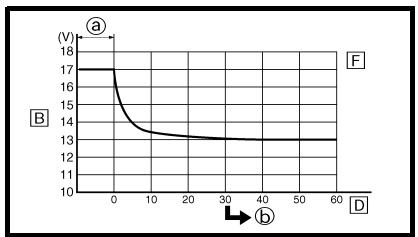
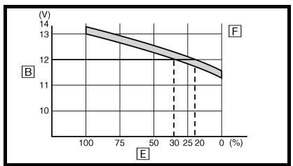
(refer to the appropriate charging method illustration)
WARNING
Do not quick charge a battery.
CAUTION:
- Never remove the MF battery sealing caps.
- Do not use a high-rate battery charger since it forces a high-amperage current into the battery quickly and can cause battery overheating and battery plate damage.
- If it is impossible to regulate the charging current on the battery charger, be careful not to overcharge the battery.
- When charging a battery, be sure to remove it from the machine. (If charging has to be done with the battery mounted on the machine, disconnect the negative battery lead from the battery terminal.)
- To reduce the chance of sparks, do not plug in the battery charger until the battery charger leads are connected to the battery.
- Before removing the battery charger lead clips from the battery terminals, be sure to turn off the battery charger.
- Make sure the battery charger lead clips are in full contact with the battery terminal and that they are not shorted. A corroded battery charger lead clip may generate heat in the contact area and a weak clip spring may cause sparks.
- If the battery becomes hot to the touch at any time during the charging process, disconnect the battery charger and let the battery cool before reconnecting it. Hot batteries can explode!
-
As shown in the following illustration, the open-circuit voltage of an MF battery stabilizes about 30 minutes after charging has been completed. Therefore, wait 30 minutes after charging is completed before measuring the open-circuit voltage.
-
Charger:
-
batterie
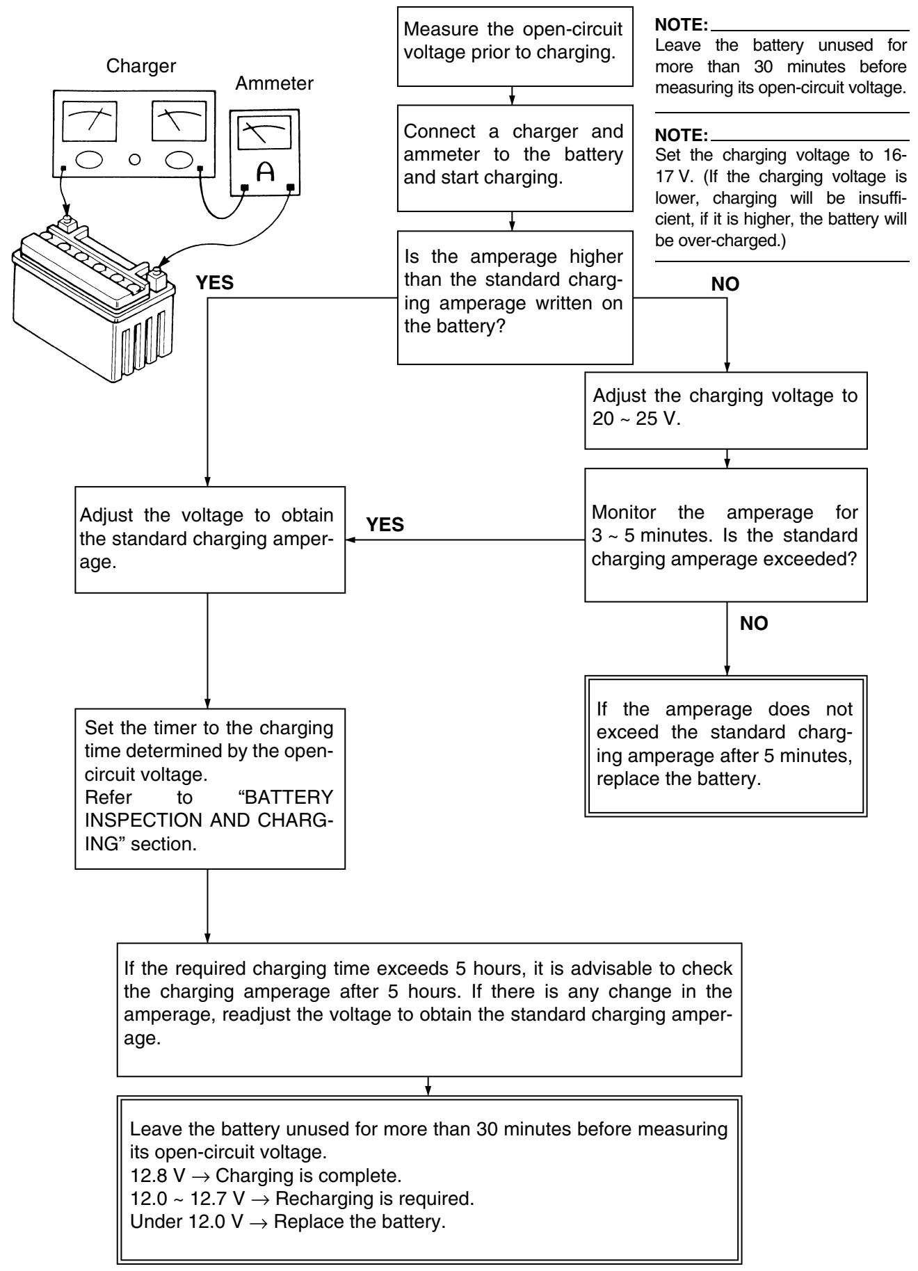
Charging method using a variable voltage charger
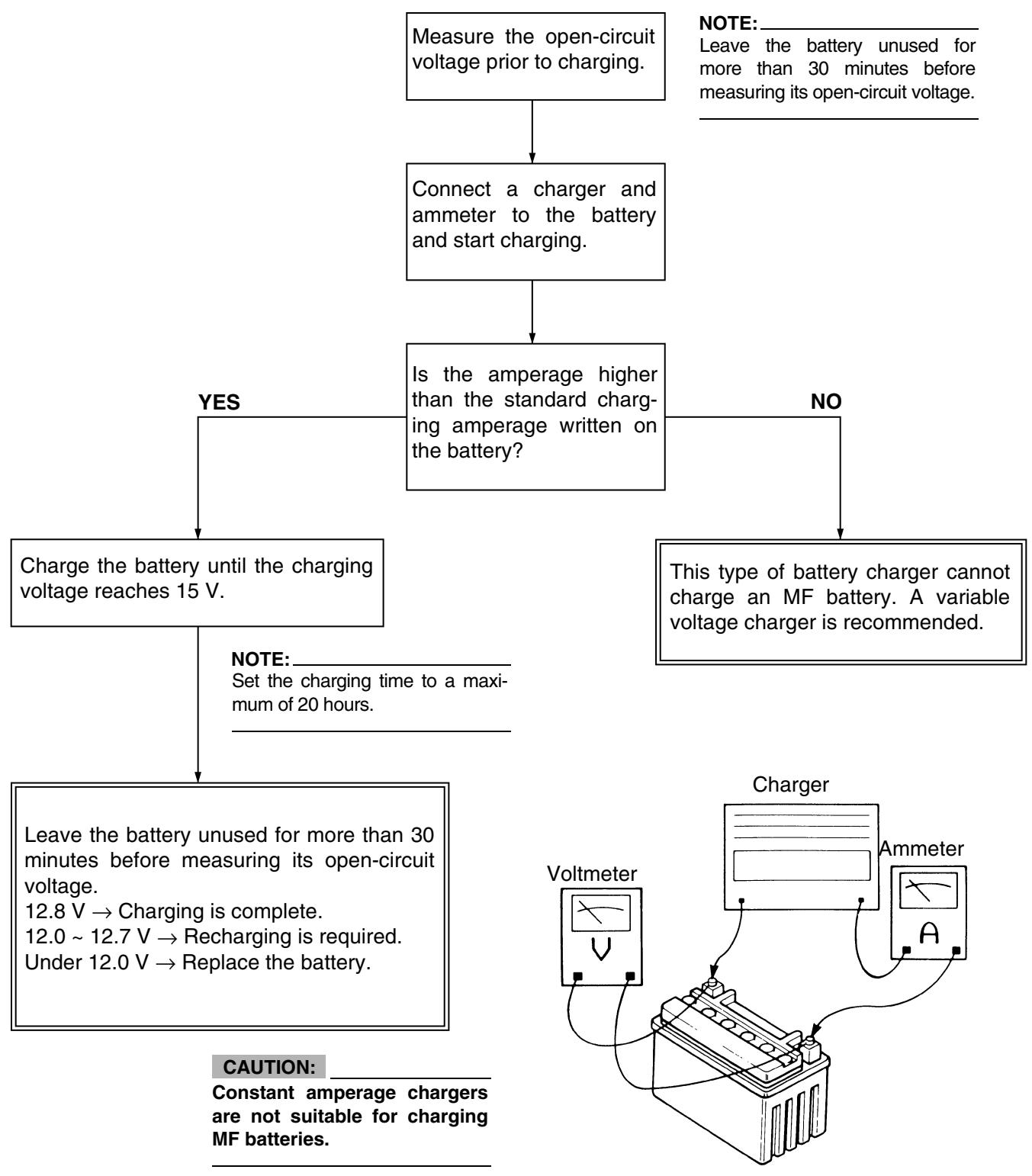
Charging method using a constant voltage charger
Battery
- Battery band
-
Connect:
-
Battery leads (to the battery terminals)
CAUTION:
First, connect the positive lead ①, then the negative lead ②.
-
Check:
-
Battery terminals
Dirt Clean with a wire brush.
Loose connection Connect properly.
-
Lubricate:
-
Battery terminal

Recommended
lubricant:
Lithium soap base grease
-
Install:
-
Seat
BATTERY REPLACEMENT
- Replace:
Battery
CAUTION:
This battery is for YAMAHA WR250F.
After filling the battery with electrolyte, either charge it for at least 3 hours at the amperage specified on the battery or let it sit for at least 15 hours before using it.
To avoid a short circuit, always set the main switch to "OFF" when checking or replacing a fuse.
-
Remove:
-
Seat
- Fuse cover
CONTROLE DES FUSIBLES
ATTENTION:
| Replacement steps: · Set the main switch to “OFF”. · Install a new fuse of the correct amperage. · Set on the switches to verify if the electrical circuit is operational. · If the fuse immediately blows again, check the electrical circuit. | ||
| Items | Amperagerating | Q’ty |
| Main fuse | 10 A | 1 |
WARNING
Never use a fuse with an amperage rating other than that specified. Improvising or using a fuse with the wrong amperage rating may cause extensive damage to the electrical system, cause the starting and ignition systems to malfunction and could possibly cause a fire.
-
Install:
-
Fuse cover
-
Seat
-
Remplacer:
-
Fusible grillé
REPLACING THE HEADLIGHT BULBS
-
Remove:
-
Headlight
Refer to "SEAT, FUEL TANK AND SIDE COVERS".
REEMPLACEMENT DES AMPOULES DE PHARE
-
Déposer:
-
Phare
Se reporter à la section "SELLE, RESERVOIR DE CARBURANT ET CACHES LATERAUX".
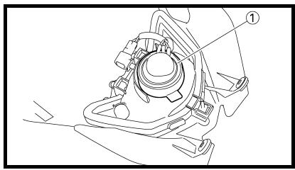
-
Remove:
-
Headlight bulb holder cover ①
-
Déposer:
Protection du porte-ampoule de phare ①
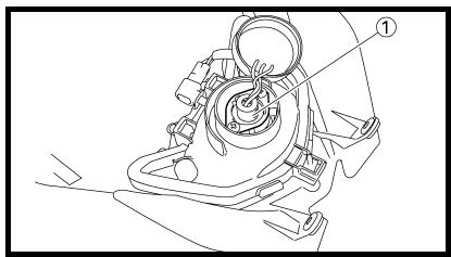
-
Remove:
-
Headlight bulb holder ①
NOTE:
Remove the headlight bulb holder by pushing it in and turning it counterclockwise.
-
Remove:
-
Headlight bulb
WARNING
Since the headlight bulb gets extremely hot, keep flammable products and your hands away from the bulb unit it has cooled down.
-
Install:
-
Headlight bulb
New
CAUTION:
Avoid touching the glass part of the headlight bulb to keep it free form oil, otherwise the transparency of the glass, the life of the bulb and the luminous flux will be adversely affected. If the headlight bulb gets soiled, thoroughly clean it with a cloth moistened with alcohol or lacquer thinner.
-
Install:
-
Headlight bulb holder
-
Install:
-
Headlight bulb holder cover
-
Install:
-
Headlight
7 Nm (0.7 m · kg, 5.1 ft · lb) Refer to "SEAT, FUEL TANK AND SIDE COVERS".
-
Déposer:
-
Porte-ampoule de phare ①
N.B.:
-
Adjust:
-
Headlight beam (vertically)
| Adjusting steps: ·Turn the adjusting screw ① in direction ⑧ or ⑥. | |
| Direction ⑧ | Headlight beam is raised. |
| Direction ⑥ | Headlight beam is lowered. |
- The air/fuel mixture will vary depending on atmospheric conditions. Therefore, it is necessary to take into consideration the air pressure, ambient temperature, humidity, etc., when adjusting the carburetor.
- Perform a test run to check for proper engine performance (e.g., throttle response) and spark plug(s) discoloration or fouling. Use these readings to determine the best possible carburetor setting.
NOTE:
It is recommended to keep a record of all carburetor settings and external conditions (e.g., atmospheric conditions, track/surface conditions, lap times) to make future carburetor setting easier.
WARNING
- The carburetor is a part of the fuel line. Therefore, be sure to install it in a well-ventilated area, away from flammable objects and any sources of fire.
- Never look into the carburetor intake. Flames may shoot out from the pipe if the engine backfires while it is being started. Gasoline may be discharged from the accelerator pump nozzle when the carburetor has been removed.
MISE AU POINT
MOTEUR
- The carburetor is extremely sensitive to foreign matter (dirt, sand, water, etc.). During installation, do not allow foreign matter to get into the carburetor.
- Always handle the carburetor and its components carefully. Even slight scratches, bends or damage to carburetor parts may prevent the carburetor from functioning correctly. Carefully perform all servicing with the appropriate tools and without applying excessive force.
- When the engine is stopped or when riding at no load, do not open and close the throttle unnecessarily. Otherwise, too much fuel may be discharged, starting may become difficult or the engine may not run well.
- After installing the carburetor, check that the throttle operates correctly and opens and closes smoothly.
Atmospheric conditions and carburetor settings
| Air temp. | Humidity | Air pressure (altitude) | Mixture | Setting |
| High | High | Low (high) | Richer | Leaner |
| Low | Low | High (low) | Leaner | Richer |
The air density (i.e., concentration of oxygen in the air) determines the richness or leanness of the air/ fuel mixture. Therefore, refer to the above table for mixture settings.
That is:
- Higher temperature expands the air with its resultant reduced density.
- Higher humidity reduces the amount of oxygen in the air by so much of the water vapor in the same air.
- Lower atmospheric pressure (at a high altitude) reduces the density of the air.
ATTENTION:
Effects of the setting parts on the throttle valve opening
A Closed
B Fully open
① Pilot jet
② Throttle valve cutaway
③ Jet needle
④ Main jet
The FLATCR carburetor has a primary main jet. This type of main jet is perfect for racing machines since it supplies an even flow of fuel, even at full load. Use the main jet and the jet needle to set the carburetor.
① Jet needle
② Pilot air jet
③ Needle jet
④ Main jet
⑤ Pilot jet
Système principal
The richness of the air-fuel mixture at full throttle can be set by changing the main jet ①.
| Standard main jet | #170 |
If the air-fuel mixture is too rich or too lean, the engine power will drop, resulting in poor acceleration.
Effects of changing the main jet (reference)
A Idle
B Fully open
① #180
② #160
③ #170
Pilot jet adjustment
The richness of the air-fuel mixture with the throttle open 1/4 or less can be set by adjusting the pilot jet ①.
| Standard pilot jet | #42 |
Effects of adjusting the pilot jet (reference)
A Idle
B Fully open
① #45
② #40
③ #42
Jet needle groove position adjustment
NOTE:
For setting adjustment, replace the standard jet needle with the one designed for setting.
Adjusting the jet needle ① position affects the acceleration when the throttle is 1/8 to 3/4 open.
- Too rich at intermediate speeds Rough engine operation is felt and the engine will not pick up speed smoothly. In this case, step up the jet needle clip by one groove and move down the needle to lean out the mixture.
- Too lean at intermediate speeds The engine breathes hard and will not pick up speed quickly. Step down the jet needle clip by one groove and move up the needle to enrich the mixture.
Effects of changing the jet needle groove position (reference)
A Idle
B Fully open
① No.6 groove
② No.4 groove
③ No.5 groove
Jet needle adjustment
The jet needle is adjusted by changing it.
| Supplied jet needle | GDEPS * GDEPR |
- For AUS, NZ, CDN and ZA
The tapered sections of all jet needles have the same starting positions, but the needles are available with different straight-partion diameters.
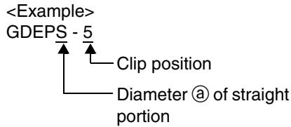
Effects of changing the jet needle (reference)
(Diameter of the straight portion)
Changing the diameter of the straight portion adjusts the air-fuel mixture when the throttle is 1/8 to 1/4 open.
A Idle
B Fully open
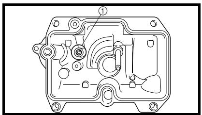
Leak jet adjustment (accelerator pump adjustment)
The leak jet ① is a setting part that adjusts the flow of fuel discharged by the accelerator pump. Since the accelerator pump operates only when throttle is open, the leak jet is used to adjust a fuel mixture ratio for quick throttle opening and is therefore different from other setting parts that adjust a fuel mixture for each throttle opening (each engine speed).
- The engine breathes hard in quick throttle opening. Select a leak jet having lower calibrating No. than standard to enrich the mixture.
#70 → #65 - Rough engine operation is felt in quick throttle opening. Select a leak jet having higher calibrating No. than standard to lean out the mixture.
#70 → #85
| Standard leak jet | #70 |
Relationship with throttle opening
The flow of the fuel through the carburetor main system is controlled by the main jet and then, it is further regulated by the area between the main nozzle and the jet needle.
The fuel flow relates to the diameter of the straight portion of the jet needle with the throttle 1/8 to 1/4 open and relates to the clip position with the throttle 1/8 to 3/4 open.
Therefore, the fuel flow is balanced at each stage of throttle opening by the combination of the jet needle straight portion diameter and clip position.
Carburetor setting parts
| Part name | Size | Part number |
| Main jet Rich(STD) | #182 | 4MX-14943-94 |
| #180 | 4MX-14943-43 | |
| #178 | 4MX-14943-93 | |
| #175 | 4MX-14943-42 | |
| #172 | 4MX-14943-92 | |
| #170 | 4MX-14943-41 | |
| #168 | 4MX-14943-91 | |
| #165 | 4MX-14943-40 | |
| #162 | 4MX-14943-90 | |
| #160 | 4MX-14943-39 | |
| Lean | #158 | 4MX-14943-89 |
| Pilot jet Rich(STD) | #50 | 4MX-14948-07 |
| #48 | 4MX-14948-06 | |
| #45 | 4MX-14948-05 | |
| #42 | 4MX-14948-04 | |
| #40 | 4MX-14948-03 | |
| Jet needle RichLean | #EPN | 5UM-14916-BN |
| #EPP | 5UM-14916-BP | |
| #EPQ | 5UM-14916-B1 | |
| #EPR | 5UM-14916-BR | |
| #EPS | 5UM-14916-BS | |
| #EPT | 5UM-14916-BT | |
| #EPU | 5UM-14916-BU | |
| #EPV | 5UM-14916-BV | |
| Leak jet Rich(STD) | #60 | 4JT-1494F-11 |
| #70 | 4JT-1494F-15 | |
| #80 | 4JT-1494F-19 | |
| #90 | 4JT-1494F-23 | |
| #100 | 4JT-1494F-27 | |
| #110 | 4JT-1494F-29 | |
| Lean | #120 | 4JT-1494F-31 |
Examples of carburetor setting depending on symptom
| Symptom | Setting | Checking |
| At full throttle Hard breathing Shearing noise Whitish spark plug ↓ Lean mixture | Increase main jet calibration no. (Gradually) | Discoloration of spark plug → If tan color, it is in good condition. If cannot be corrected: Clogged float valve seat Clogged fuel hose Clogged fuel cock Check that the accelerator pump operates smoothly. |
| At full throttle Speed pick-up stops Slow speed pick-up Slow response Sooty spark plug ↓ Rich mixture | Decrease main jet calibration no. (Gradually) | Discoloration of spark plug → If tan color, it is in good condition. If cannot be corrected: Clogged air filter Fuel overflow from carburetor |
| Lean mixture | Lower jet needle clip position. (1 groove down) | The clip position is the jet needle groove on which the clip is installed. The positions are numbered from the top. Check that the accelerator pump operates smoothly. (except for rich mixture symptom). |
| Rich mixture | Raise jet needle clip position. (1 groove up) | |
| 1/4 ~ 3/4 throttle Hard breathing Lack of speed | Lower jet needle clip position. (1 groove down) | |
| 1/4 ~ 1/2 throttle Slow speed pick-up Poor acceleration | Raise jet needle clip position. (1 groove up) | |
| Closed to 1/4 throttle Hard breathing Speed down | Use jet needle with a smaller diameter. | Slow-speed-circuit passage Clogged → Clean. Overflow from carburetor |
| Closed to 1/4 throttle Poor acceleration | Use jet needle with a larger diameter. Raise jet needle clip position. (1 groove up) | |
| Poor response in the low to intermediate speeds | Raise jet needle clip position. If this has no effect, lower the jet needle clip position. | |
| Poor response when throttle is opened quickly | Check overall settings. Use main jet with a lower calibration no. Raise jet needle clip position. (1 groove up) If these have no effect, use a main jet with a higher calibration no. and lower the jet needle clip position. | Check air filter for fouling. Check that the accelerator pump operates smoothly. |
- This should be taken simply for an example. It is necessary to set the carburetor while checking the operating conditions of the engine.
Selection of the secondary reduction ratio (Sprocket)
| Secondary reduction ratio | Number of rear wheel sprocket teeth |
| Number of drive sprocket teeth |
| Standard secondary reduction ratio | 50/13 (3.846) |
- It is generally said that the secondary gear ratio should be reduced for a longer straight portion of a speed course and should be increased for a course with many corners. Actually, however, as the speed depends on the ground condition of the day of the ride, be sure to run through the circuit to set the machine suitable for the entire course.
- In actuality, it is very difficult to achieve settings suitable for the entire course and some settings may be sacrificed. Thus, the settings should be matched to the portion of the course that has the greatest effect on the ride result. In such a case, run through the entire course while making notes of lap times to find the best balance; then, determine the secondary reduction ratio.
- If a course has a long straight portion where a machine can run at maximum speed, the machine is generally set such that it can develop its maximum revolutions toward the end of the straight line, with care taken to avoid the engine over-revving.
NOTE:
Riding technique varies from rider to rider and the performance of a machine also vary from machine to machine. Therefore, do not imitate other rider's settings from the beginning but choose your own setting according to the level of your riding technique.
CHÄSSIS
Drive and rear wheel sprockets setting parts
| Part namecia de la bobina captadora | Sizeina captadora | Part numberd>ición del selector del com-probador | ||||||||||||||||||||||||||||||||||||||||||||||||||||||||||||||||||||||||||||||||||||||||||||||||||||||||||||||||||||||||||||||||||||||||||||||||||||
| Drive sprocket ① (STD)e> | 13Tsistencia de la bobina captadora | 9383B-13218na captadora | ptadora||||||||||||||||||||||||||||||||||||||||||||||||||||||||||||||||||||||||||||||||||||||||||||||||||||||||||||||||||||||||||||||||||||||||||||||||||||
| * 14Tsición del selector del com-probador | 9383B-14222del com-probador | om-probador|||||||||||||||||||||||||||||||||||||||||||||||||||||||||||||||||||||||||||||||||||||||||||||||||||||||||||||||||||||||||||||||||||||||||||||||||||||
| Rear wheel sprocket ②omprobacion-del-interrupuctor-de-lux-de-punto-muerto"> | 48Tdel-interrupuctor-de-lux-de-punto-muerto"> | 5GS-25448-50lux-de-punto-muerto">e-punto-muerto"> | ||||||||||||||||||||||||||||||||||||||||||||||||||||||||||||||||||||||||||||||||||||||||||||||||||||||||||||||||||||||||||||||||||||||||||||||||||||
| * 48TMPROBACION DEL INTERRUPUCTOR DE LUX DE PUNTO MUERTO | 1C3-25448-00UPUCTOR DE LUX DE PUNTO MUERTOOR DE LUX DE PUNTO MUERTO | |||||||||||||||||||||||||||||||||||||||||||||||||||||||||||||||||||||||||||||||||||||||||||||||||||||||||||||||||||||||||||||||||||||||||||||||||||||
| * 49T MUERTO | 1C3-25449-00robar:
- Conducto del interruptor de luz de punto muerto
|
* AUS et NZ
EC721002
Tire pressure>
Tire pressure should be adjust to suit the road surface condition of the circuit.

Standard tire pressure: 100 kPa (1.0 kgf/cm², 15 psi)
- Under a rainy, muddy, sandy, or slippery condition, the tire pressure should be lower for a larger area of contact with the road surface.

Extent of adjustment: 60 80kPa (0.6 0.8kgf / cm^2 9.0 12 psi)
- Under a stony or hard road condition, the tire pressure should be higher to prevent a flat tire.

Extent of adjustment: 100 ~ 120 kPa (1.0 ~ 1.2 kgf /cm², 15 ~ 18 psi)
Pression des pneus motor can only operate if at least one of the following conditions is met:
- The transmission is in neutral (the neutral switch is closed).
- The clutch lever is pulled to the handlebar (the clutch switch is closed).
The starting circuit cut-off relay prevents the starter motor from operating when neither of these conditions has been met. In this instance, the starting circuit cut-off relay is open so current cannot reach the starter motor. When at least one of the above conditions has been met the starting circuit cut-off relay is closed and the engine can be started by pressing the start switch.

WHEN THE TRANSMISSION IS IN NEUTRAL

WHEN THE CLUTCH
LEVER IS PULLED
TO THE HANDLEBAR
① Battery
② Main fuse
③ Main switch
④ Starting circuit cut-off relay
⑤ Start switch
⑥ Diode
⑦ Clutch switch
Neutral switch
⑨ Starter relay
10 Starter motor
Régler la pression des pneus en fonction des conditions du terrain.

WHEN THE TRANSMISSION IS IN NEUTRAL

WHEN THE CLUTCH
LEVER IS PULLED
TO THE HANDLEBAR
① Battery
② Main fuse
③ Main switch
④ Starting circuit cut-off relay
⑤ Start switch
⑥ Diode
⑦ Clutch switch
Neutral switch
⑨ Starter relay
10 Starter motor - 1](/content/2025/01/114874/images/ad31244a8c298aad1f752f51434a38d72d7c27741605d87ec183807ba9f93592.jpg)
Pression des pneus standard: 100 kPa (1,0 kgf/cm², 15 psi)
- En cas de conduite sous la pluie, sur terrain boueux, sablonneux ou glissant, réduire la pression des pneus pour une meilleure adherence.

WHEN THE TRANSMISSION IS IN NEUTRAL

WHEN THE CLUTCH
LEVER IS PULLED
TO THE HANDLEBAR
① Battery
② Main fuse
③ Main switch
④ Starting circuit cut-off relay
⑤ Start switch
⑥ Diode
⑦ Clutch switch
Neutral switch
⑨ Starter relay
10 Starter motor - 2](/content/2025/01/114874/images/b086406bee4aab9635f1fdb12831097e2fcfbcab6ac1d0aeca8956018da80a6b.jpg)
Plage de réglage:
60 à 80 kPa
(0,6 à 0,8 kgf/cm², 9,0 à 12 psi)
- Sur route pavée ou sur surface dure, augmenter la pression des pneus afin d'éviter les crevaisons.

WHEN THE TRANSMISSION IS IN NEUTRAL

WHEN THE CLUTCH
LEVER IS PULLED
TO THE HANDLEBAR
① Battery
② Main fuse
③ Main switch
④ Starting circuit cut-off relay
⑤ Start switch
⑥ Diode
⑦ Clutch switch
Neutral switch
⑨ Starter relay
10 Starter motor - 3](/content/2025/01/114874/images/3ef1af3bfdf376e2e33f5c693af9ff0dd7e6f06258d3c66142bf650136e48616.jpg)
Plage de réglage: 100 à 120 kPa (1,0 à 1,2 kgf/cm², 15 à 18 psi)
Verfügbare Antriebsritzel und Kettenräder
Bauteilarter relay
10 Starter motor
r }$
Antriebsritzel ① (STD)LECTRIQUE | 13T1> | 9383B-13218nement-du-dispositif-de-coupure-du-circuit-de-demarrage">t-du-dispositif-de-coupure-du-circuit-de-demarrage"> | *14Te-coupure-du-circuit-de-demarrage"> | 9383B-14222-de-demarrage">emarrage"> | Kettenrad ②IF DE COUPURE DU CIRCUIT DE DEMARRAGE | 48TE DU CIRCUIT DE DEMARRAGE | 5GS-25448-50RAGE/h1> | *48Tcteur a clé est sur "ON", le démarreur ne peut fonctionner que si l'une au moins des conditions suivantes est remplie:
- la boîte de vitesses est au point mort (le circuit du contacteur de point mort est fermé).
- le levier d'embrayage est tiré vers le guidon (le contacteur d'embrayage est fermé).
Le relais de coupe-circuit de démarrage empêche le démarreur de fonctionner lorsque aucune des deux conditions n'est remplie. Dans ce cas, le relais de coupe-circuit de démarrage est ouvert, de sorte que le courant ne peut atteindre le démarreur. Lorsqu'une au moins des conditions ci-dessus est remplie, le relais de coupe-circuit de démarrage est fermé et le moteur peut être démarré à l'aide du contacteur du démarreur.

LORSQUE LA BOITE DE VITESSE EST AU POINT MORT

LORSQUE LE LEVIER D'EMBRAYAGE EST TIRE VERS LE GUIDON
① Batterie
② Fusible principal
③ Contacteur a clé
④ Relais de coupe-circuit de démarrage
⑤ Contacteur du démarreur
⑥ Diode
⑦ Contacteur d'embrayage
⑧ Contacteur de point mort
⑨ Relais de démarreur
Démarreur
|
le démarreur ne peut fonctionner que si l'une au moins des conditions suivantes est remplie:
- la boîte de vitesses est au point mort (le circuit du contacteur de point mort est fermé).
- le levier d'embrayage est tiré vers le guidon (le contacteur d'embrayage est fermé).
Le relais de coupe-circuit de démarrage empêche le démarreur de fonctionner lorsque aucune des deux conditions n'est remplie. Dans ce cas, le relais de coupe-circuit de démarrage est ouvert, de sorte que le courant ne peut atteindre le démarreur. Lorsqu'une au moins des conditions ci-dessus est remplie, le relais de coupe-circuit de démarrage est fermé et le moteur peut être démarré à l'aide du contacteur du démarreur.

LORSQUE LA BOITE DE VITESSE EST AU POINT MORT

LORSQUE LE LEVIER D'EMBRAYAGE EST TIRE VERS LE GUIDON
① Batterie
② Fusible principal
③ Contacteur a clé
④ Relais de coupe-circuit de démarrage
⑤ Contacteur du démarreur
⑥ Diode
⑦ Contacteur d'embrayage
⑧ Contacteur de point mort
⑨ Relais de démarreur
Démarreur
*49Teut fonctionner que si l'une au moins des conditions suivantes est remplie:
- la boîte de vitesses est au point mort (le circuit du contacteur de point mort est fermé).
- le levier d'embrayage est tiré vers le guidon (le contacteur d'embrayage est fermé).
Le relais de coupe-circuit de démarrage empêche le démarreur de fonctionner lorsque aucune des deux conditions n'est remplie. Dans ce cas, le relais de coupe-circuit de démarrage est ouvert, de sorte que le courant ne peut atteindre le démarreur. Lorsqu'une au moins des conditions ci-dessus est remplie, le relais de coupe-circuit de démarrage est fermé et le moteur peut être démarré à l'aide du contacteur du démarreur.

LORSQUE LA BOITE DE VITESSE EST AU POINT MORT

LORSQUE LE LEVIER D'EMBRAYAGE EST TIRE VERS LE GUIDON
① Batterie
② Fusible principal
③ Contacteur a clé
④ Relais de coupe-circuit de démarrage
⑤ Contacteur du démarreur
⑥ Diode
⑦ Contacteur d'embrayage
⑧ Contacteur de point mort
⑨ Relais de démarreur
Démarreur
|
ne au moins des conditions suivantes est remplie:
- la boîte de vitesses est au point mort (le circuit du contacteur de point mort est fermé).
- le levier d'embrayage est tiré vers le guidon (le contacteur d'embrayage est fermé).
Le relais de coupe-circuit de démarrage empêche le démarreur de fonctionner lorsque aucune des deux conditions n'est remplie. Dans ce cas, le relais de coupe-circuit de démarrage est ouvert, de sorte que le courant ne peut atteindre le démarreur. Lorsqu'une au moins des conditions ci-dessus est remplie, le relais de coupe-circuit de démarrage est fermé et le moteur peut être démarré à l'aide du contacteur du démarreur.

LORSQUE LA BOITE DE VITESSE EST AU POINT MORT

LORSQUE LE LEVIER D'EMBRAYAGE EST TIRE VERS LE GUIDON
① Batterie
② Fusible principal
③ Contacteur a clé
④ Relais de coupe-circuit de démarrage
⑤ Contacteur du démarreur
⑥ Diode
⑦ Contacteur d'embrayage
⑧ Contacteur de point mort
⑨ Relais de démarreur
Démarreur
(STD)nditions suivantes est remplie:
- la boîte de vitesses est au point mort (le circuit du contacteur de point mort est fermé).
- le levier d'embrayage est tiré vers le guidon (le contacteur d'embrayage est fermé).
Le relais de coupe-circuit de démarrage empêche le démarreur de fonctionner lorsque aucune des deux conditions n'est remplie. Dans ce cas, le relais de coupe-circuit de démarrage est ouvert, de sorte que le courant ne peut atteindre le démarreur. Lorsqu'une au moins des conditions ci-dessus est remplie, le relais de coupe-circuit de démarrage est fermé et le moteur peut être démarré à l'aide du contacteur du démarreur.

LORSQUE LA BOITE DE VITESSE EST AU POINT MORT

LORSQUE LE LEVIER D'EMBRAYAGE EST TIRE VERS LE GUIDON
① Batterie
② Fusible principal
③ Contacteur a clé
④ Relais de coupe-circuit de démarrage
⑤ Contacteur du démarreur
⑥ Diode
⑦ Contacteur d'embrayage
⑧ Contacteur de point mort
⑨ Relais de démarreur
Démarreur
|
boîte de vitesses est au point mort (le circuit du contacteur de point mort est fermé).
- le levier d'embrayage est tiré vers le guidon (le contacteur d'embrayage est fermé).
Le relais de coupe-circuit de démarrage empêche le démarreur de fonctionner lorsque aucune des deux conditions n'est remplie. Dans ce cas, le relais de coupe-circuit de démarrage est ouvert, de sorte que le courant ne peut atteindre le démarreur. Lorsqu'une au moins des conditions ci-dessus est remplie, le relais de coupe-circuit de démarrage est fermé et le moteur peut être démarré à l'aide du contacteur du démarreur.

LORSQUE LA BOITE DE VITESSE EST AU POINT MORT

LORSQUE LE LEVIER D'EMBRAYAGE EST TIRE VERS LE GUIDON
① Batterie
② Fusible principal
③ Contacteur a clé
④ Relais de coupe-circuit de démarrage
⑤ Contacteur du démarreur
⑥ Diode
⑦ Contacteur d'embrayage
⑧ Contacteur de point mort
⑨ Relais de démarreur
Démarreur
*(STD)st au point mort (le circuit du contacteur de point mort est fermé).
- le levier d'embrayage est tiré vers le guidon (le contacteur d'embrayage est fermé).
Le relais de coupe-circuit de démarrage empêche le démarreur de fonctionner lorsque aucune des deux conditions n'est remplie. Dans ce cas, le relais de coupe-circuit de démarrage est ouvert, de sorte que le courant ne peut atteindre le démarreur. Lorsqu'une au moins des conditions ci-dessus est remplie, le relais de coupe-circuit de démarrage est fermé et le moteur peut être démarré à l'aide du contacteur du démarreur.

LORSQUE LA BOITE DE VITESSE EST AU POINT MORT

LORSQUE LE LEVIER D'EMBRAYAGE EST TIRE VERS LE GUIDON
① Batterie
② Fusible principal
③ Contacteur a clé
④ Relais de coupe-circuit de démarrage
⑤ Contacteur du démarreur
⑥ Diode
⑦ Contacteur d'embrayage
⑧ Contacteur de point mort
⑨ Relais de démarreur
Démarreur
|
eur de point mort est fermé).
- le levier d'embrayage est tiré vers le guidon (le contacteur d'embrayage est fermé).
Le relais de coupe-circuit de démarrage empêche le démarreur de fonctionner lorsque aucune des deux conditions n'est remplie. Dans ce cas, le relais de coupe-circuit de démarrage est ouvert, de sorte que le courant ne peut atteindre le démarreur. Lorsqu'une au moins des conditions ci-dessus est remplie, le relais de coupe-circuit de démarrage est fermé et le moteur peut être démarré à l'aide du contacteur du démarreur.

LORSQUE LA BOITE DE VITESSE EST AU POINT MORT

LORSQUE LE LEVIER D'EMBRAYAGE EST TIRE VERS LE GUIDON
① Batterie
② Fusible principal
③ Contacteur a clé
④ Relais de coupe-circuit de démarrage
⑤ Contacteur du démarreur
⑥ Diode
⑦ Contacteur d'embrayage
⑧ Contacteur de point mort
⑨ Relais de démarreur
Démarreur
mort est fermé).
- le levier d'embrayage est tiré vers le guidon (le contacteur d'embrayage est fermé).
Le relais de coupe-circuit de démarrage empêche le démarreur de fonctionner lorsque aucune des deux conditions n'est remplie. Dans ce cas, le relais de coupe-circuit de démarrage est ouvert, de sorte que le courant ne peut atteindre le démarreur. Lorsqu'une au moins des conditions ci-dessus est remplie, le relais de coupe-circuit de démarrage est fermé et le moteur peut être démarré à l'aide du contacteur du démarreur.

LORSQUE LA BOITE DE VITESSE EST AU POINT MORT

LORSQUE LE LEVIER D'EMBRAYAGE EST TIRE VERS LE GUIDON
① Batterie
② Fusible principal
③ Contacteur a clé
④ Relais de coupe-circuit de démarrage
⑤ Contacteur du démarreur
⑥ Diode
⑦ Contacteur d'embrayage
⑧ Contacteur de point mort
⑨ Relais de démarreur
Démarreur
|
yage est tiré vers le guidon (le contacteur d'embrayage est fermé).
Le relais de coupe-circuit de démarrage empêche le démarreur de fonctionner lorsque aucune des deux conditions n'est remplie. Dans ce cas, le relais de coupe-circuit de démarrage est ouvert, de sorte que le courant ne peut atteindre le démarreur. Lorsqu'une au moins des conditions ci-dessus est remplie, le relais de coupe-circuit de démarrage est fermé et le moteur peut être démarré à l'aide du contacteur du démarreur.

LORSQUE LA BOITE DE VITESSE EST AU POINT MORT

LORSQUE LE LEVIER D'EMBRAYAGE EST TIRE VERS LE GUIDON
① Batterie
② Fusible principal
③ Contacteur a clé
④ Relais de coupe-circuit de démarrage
⑤ Contacteur du démarreur
⑥ Diode
⑦ Contacteur d'embrayage
⑧ Contacteur de point mort
⑨ Relais de démarreur
Démarreur
vers le guidon (le contacteur d'embrayage est fermé).
Le relais de coupe-circuit de démarrage empêche le démarreur de fonctionner lorsque aucune des deux conditions n'est remplie. Dans ce cas, le relais de coupe-circuit de démarrage est ouvert, de sorte que le courant ne peut atteindre le démarreur. Lorsqu'une au moins des conditions ci-dessus est remplie, le relais de coupe-circuit de démarrage est fermé et le moteur peut être démarré à l'aide du contacteur du démarreur.

LORSQUE LA BOITE DE VITESSE EST AU POINT MORT

LORSQUE LE LEVIER D'EMBRAYAGE EST TIRE VERS LE GUIDON
① Batterie
② Fusible principal
③ Contacteur a clé
④ Relais de coupe-circuit de démarrage
⑤ Contacteur du démarreur
⑥ Diode
⑦ Contacteur d'embrayage
⑧ Contacteur de point mort
⑨ Relais de démarreur
Démarreur
|
yage est fermé).
Le relais de coupe-circuit de démarrage empêche le démarreur de fonctionner lorsque aucune des deux conditions n'est remplie. Dans ce cas, le relais de coupe-circuit de démarrage est ouvert, de sorte que le courant ne peut atteindre le démarreur. Lorsqu'une au moins des conditions ci-dessus est remplie, le relais de coupe-circuit de démarrage est fermé et le moteur peut être démarré à l'aide du contacteur du démarreur.

LORSQUE LA BOITE DE VITESSE EST AU POINT MORT

LORSQUE LE LEVIER D'EMBRAYAGE EST TIRE VERS LE GUIDON
① Batterie
② Fusible principal
③ Contacteur a clé
④ Relais de coupe-circuit de démarrage
⑤ Contacteur du démarreur
⑥ Diode
⑦ Contacteur d'embrayage
⑧ Contacteur de point mort
⑨ Relais de démarreur
Démarreur
é).
Le relais de coupe-circuit de démarrage empêche le démarreur de fonctionner lorsque aucune des deux conditions n'est remplie. Dans ce cas, le relais de coupe-circuit de démarrage est ouvert, de sorte que le courant ne peut atteindre le démarreur. Lorsqu'une au moins des conditions ci-dessus est remplie, le relais de coupe-circuit de démarrage est fermé et le moteur peut être démarré à l'aide du contacteur du démarreur.

LORSQUE LA BOITE DE VITESSE EST AU POINT MORT

LORSQUE LE LEVIER D'EMBRAYAGE EST TIRE VERS LE GUIDON
① Batterie
② Fusible principal
③ Contacteur a clé
④ Relais de coupe-circuit de démarrage
⑤ Contacteur du démarreur
⑥ Diode
⑦ Contacteur d'embrayage
⑧ Contacteur de point mort
⑨ Relais de démarreur
Démarreur
|
rrage empêche le démarreur de fonctionner lorsque aucune des deux conditions n'est remplie. Dans ce cas, le relais de coupe-circuit de démarrage est ouvert, de sorte que le courant ne peut atteindre le démarreur. Lorsqu'une au moins des conditions ci-dessus est remplie, le relais de coupe-circuit de démarrage est fermé et le moteur peut être démarré à l'aide du contacteur du démarreur.

LORSQUE LA BOITE DE VITESSE EST AU POINT MORT

LORSQUE LE LEVIER D'EMBRAYAGE EST TIRE VERS LE GUIDON
① Batterie
② Fusible principal
③ Contacteur a clé
④ Relais de coupe-circuit de démarrage
⑤ Contacteur du démarreur
⑥ Diode
⑦ Contacteur d'embrayage
⑧ Contacteur de point mort
⑨ Relais de démarreur
Démarreur
|
* AUS und NZ
Componenti di impostazione corona della ruota posteriore e ruota dentata di trasmissione
| Denominazionespositif-de-coupure-du-circuit-de-demarrage"> | Misurapure-du-circuit-de-demarrage"> | Numero partemarrage">ge"> | ||||||||||||||||||||||||||||||||||||||||||||||||||||||||||||||||||||
| Ruota dentata di trasmissione (1) (STD)AGE | 13T le contacteur a clé est sur "ON", le démarreur ne peut fonctionner que si l'une au moins des conditions suivantes est remplie:
- la boîte de vitesses est au point mort (le circuit du contacteur de point mort est fermé).
- le levier d'embrayage est tiré vers le guidon (le contacteur d'embrayage est fermé).
Le relais de coupe-circuit de démarrage empêche le démarreur de fonctionner lorsque aucune des deux conditions n'est remplie. Dans ce cas, le relais de coupe-circuit de démarrage est ouvert, de sorte que le courant ne peut atteindre le démarreur. Lorsqu'une au moins des conditions ci-dessus est remplie, le relais de coupe-circuit de démarrage est fermé et le moteur peut être démarré à l'aide du contacteur du démarreur.

LORSQUE LA BOITE DE VITESSE EST AU POINT MORT

LORSQUE LE LEVIER D'EMBRAYAGE EST TIRE VERS LE GUIDON
① Batterie
② Fusible principal
③ Contacteur a clé
④ Relais de coupe-circuit de démarrage
⑤ Contacteur du démarreur
⑥ Diode
⑦ Contacteur d'embrayage
⑧ Contacteur de point mort
⑨ Relais de démarreur
Démarreur
sur "ON", le démarreur ne peut fonctionner que si l'une au moins des conditions suivantes est remplie:
- la boîte de vitesses est au point mort (le circuit du contacteur de point mort est fermé).
- le levier d'embrayage est tiré vers le guidon (le contacteur d'embrayage est fermé).
Le relais de coupe-circuit de démarrage empêche le démarreur de fonctionner lorsque aucune des deux conditions n'est remplie. Dans ce cas, le relais de coupe-circuit de démarrage est ouvert, de sorte que le courant ne peut atteindre le démarreur. Lorsqu'une au moins des conditions ci-dessus est remplie, le relais de coupe-circuit de démarrage est fermé et le moteur peut être démarré à l'aide du contacteur du démarreur.

LORSQUE LA BOITE DE VITESSE EST AU POINT MORT

LORSQUE LE LEVIER D'EMBRAYAGE EST TIRE VERS LE GUIDON
① Batterie
② Fusible principal
③ Contacteur a clé
④ Relais de coupe-circuit de démarrage
⑤ Contacteur du démarreur
⑥ Diode
⑦ Contacteur d'embrayage
⑧ Contacteur de point mort
⑨ Relais de démarreur
Démarreur
* 14Treur ne peut fonctionner que si l'une au moins des conditions suivantes est remplie:
- la boîte de vitesses est au point mort (le circuit du contacteur de point mort est fermé).
- le levier d'embrayage est tiré vers le guidon (le contacteur d'embrayage est fermé).
Le relais de coupe-circuit de démarrage empêche le démarreur de fonctionner lorsque aucune des deux conditions n'est remplie. Dans ce cas, le relais de coupe-circuit de démarrage est ouvert, de sorte que le courant ne peut atteindre le démarreur. Lorsqu'une au moins des conditions ci-dessus est remplie, le relais de coupe-circuit de démarrage est fermé et le moteur peut être démarré à l'aide du contacteur du démarreur.

LORSQUE LA BOITE DE VITESSE EST AU POINT MORT

LORSQUE LE LEVIER D'EMBRAYAGE EST TIRE VERS LE GUIDON
① Batterie
② Fusible principal
③ Contacteur a clé
④ Relais de coupe-circuit de démarrage
⑤ Contacteur du démarreur
⑥ Diode
⑦ Contacteur d'embrayage
⑧ Contacteur de point mort
⑨ Relais de démarreur
Démarreur
|
que si l'une au moins des conditions suivantes est remplie:
- la boîte de vitesses est au point mort (le circuit du contacteur de point mort est fermé).
- le levier d'embrayage est tiré vers le guidon (le contacteur d'embrayage est fermé).
Le relais de coupe-circuit de démarrage empêche le démarreur de fonctionner lorsque aucune des deux conditions n'est remplie. Dans ce cas, le relais de coupe-circuit de démarrage est ouvert, de sorte que le courant ne peut atteindre le démarreur. Lorsqu'une au moins des conditions ci-dessus est remplie, le relais de coupe-circuit de démarrage est fermé et le moteur peut être démarré à l'aide du contacteur du démarreur.

LORSQUE LA BOITE DE VITESSE EST AU POINT MORT

LORSQUE LE LEVIER D'EMBRAYAGE EST TIRE VERS LE GUIDON
① Batterie
② Fusible principal
③ Contacteur a clé
④ Relais de coupe-circuit de démarrage
⑤ Contacteur du démarreur
⑥ Diode
⑦ Contacteur d'embrayage
⑧ Contacteur de point mort
⑨ Relais de démarreur
Démarreur
Corona della ruota posteriore (2):
- la boîte de vitesses est au point mort (le circuit du contacteur de point mort est fermé).
- le levier d'embrayage est tiré vers le guidon (le contacteur d'embrayage est fermé).
Le relais de coupe-circuit de démarrage empêche le démarreur de fonctionner lorsque aucune des deux conditions n'est remplie. Dans ce cas, le relais de coupe-circuit de démarrage est ouvert, de sorte que le courant ne peut atteindre le démarreur. Lorsqu'une au moins des conditions ci-dessus est remplie, le relais de coupe-circuit de démarrage est fermé et le moteur peut être démarré à l'aide du contacteur du démarreur.

LORSQUE LA BOITE DE VITESSE EST AU POINT MORT

LORSQUE LE LEVIER D'EMBRAYAGE EST TIRE VERS LE GUIDON
① Batterie
② Fusible principal
③ Contacteur a clé
④ Relais de coupe-circuit de démarrage
⑤ Contacteur du démarreur
⑥ Diode
⑦ Contacteur d'embrayage
⑧ Contacteur de point mort
⑨ Relais de démarreur
Démarreur
|
mort (le circuit du contacteur de point mort est fermé).
- le levier d'embrayage est tiré vers le guidon (le contacteur d'embrayage est fermé).
Le relais de coupe-circuit de démarrage empêche le démarreur de fonctionner lorsque aucune des deux conditions n'est remplie. Dans ce cas, le relais de coupe-circuit de démarrage est ouvert, de sorte que le courant ne peut atteindre le démarreur. Lorsqu'une au moins des conditions ci-dessus est remplie, le relais de coupe-circuit de démarrage est fermé et le moteur peut être démarré à l'aide du contacteur du démarreur.

LORSQUE LA BOITE DE VITESSE EST AU POINT MORT

LORSQUE LE LEVIER D'EMBRAYAGE EST TIRE VERS LE GUIDON
① Batterie
② Fusible principal
③ Contacteur a clé
④ Relais de coupe-circuit de démarrage
⑤ Contacteur du démarreur
⑥ Diode
⑦ Contacteur d'embrayage
⑧ Contacteur de point mort
⑨ Relais de démarreur
Démarreur
* 48Tdu contacteur de point mort est fermé).
- le levier d'embrayage est tiré vers le guidon (le contacteur d'embrayage est fermé).
Le relais de coupe-circuit de démarrage empêche le démarreur de fonctionner lorsque aucune des deux conditions n'est remplie. Dans ce cas, le relais de coupe-circuit de démarrage est ouvert, de sorte que le courant ne peut atteindre le démarreur. Lorsqu'une au moins des conditions ci-dessus est remplie, le relais de coupe-circuit de démarrage est fermé et le moteur peut être démarré à l'aide du contacteur du démarreur.

LORSQUE LA BOITE DE VITESSE EST AU POINT MORT

LORSQUE LE LEVIER D'EMBRAYAGE EST TIRE VERS LE GUIDON
① Batterie
② Fusible principal
③ Contacteur a clé
④ Relais de coupe-circuit de démarrage
⑤ Contacteur du démarreur
⑥ Diode
⑦ Contacteur d'embrayage
⑧ Contacteur de point mort
⑨ Relais de démarreur
Démarreur
|
t est fermé).
- le levier d'embrayage est tiré vers le guidon (le contacteur d'embrayage est fermé).
Le relais de coupe-circuit de démarrage empêche le démarreur de fonctionner lorsque aucune des deux conditions n'est remplie. Dans ce cas, le relais de coupe-circuit de démarrage est ouvert, de sorte que le courant ne peut atteindre le démarreur. Lorsqu'une au moins des conditions ci-dessus est remplie, le relais de coupe-circuit de démarrage est fermé et le moteur peut être démarré à l'aide du contacteur du démarreur.

LORSQUE LA BOITE DE VITESSE EST AU POINT MORT

LORSQUE LE LEVIER D'EMBRAYAGE EST TIRE VERS LE GUIDON
① Batterie
② Fusible principal
③ Contacteur a clé
④ Relais de coupe-circuit de démarrage
⑤ Contacteur du démarreur
⑥ Diode
⑦ Contacteur d'embrayage
⑧ Contacteur de point mort
⑨ Relais de démarreur
Démarreur
* 49T le levier d'embrayage est tiré vers le guidon (le contacteur d'embrayage est fermé).
Le relais de coupe-circuit de démarrage empêche le démarreur de fonctionner lorsque aucune des deux conditions n'est remplie. Dans ce cas, le relais de coupe-circuit de démarrage est ouvert, de sorte que le courant ne peut atteindre le démarreur. Lorsqu'une au moins des conditions ci-dessus est remplie, le relais de coupe-circuit de démarrage est fermé et le moteur peut être démarré à l'aide du contacteur du démarreur.

LORSQUE LA BOITE DE VITESSE EST AU POINT MORT

LORSQUE LE LEVIER D'EMBRAYAGE EST TIRE VERS LE GUIDON
① Batterie
② Fusible principal
③ Contacteur a clé
④ Relais de coupe-circuit de démarrage
⑤ Contacteur du démarreur
⑥ Diode
⑦ Contacteur d'embrayage
⑧ Contacteur de point mort
⑨ Relais de démarreur
Démarreur
|
tiré vers le guidon (le contacteur d'embrayage est fermé).
Le relais de coupe-circuit de démarrage empêche le démarreur de fonctionner lorsque aucune des deux conditions n'est remplie. Dans ce cas, le relais de coupe-circuit de démarrage est ouvert, de sorte que le courant ne peut atteindre le démarreur. Lorsqu'une au moins des conditions ci-dessus est remplie, le relais de coupe-circuit de démarrage est fermé et le moteur peut être démarré à l'aide du contacteur du démarreur.

LORSQUE LA BOITE DE VITESSE EST AU POINT MORT

LORSQUE LE LEVIER D'EMBRAYAGE EST TIRE VERS LE GUIDON
① Batterie
② Fusible principal
③ Contacteur a clé
④ Relais de coupe-circuit de démarrage
⑤ Contacteur du démarreur
⑥ Diode
⑦ Contacteur d'embrayage
⑧ Contacteur de point mort
⑨ Relais de démarreur
Démarreur
(STD)on (le contacteur d'embrayage est fermé).
Le relais de coupe-circuit de démarrage empêche le démarreur de fonctionner lorsque aucune des deux conditions n'est remplie. Dans ce cas, le relais de coupe-circuit de démarrage est ouvert, de sorte que le courant ne peut atteindre le démarreur. Lorsqu'une au moins des conditions ci-dessus est remplie, le relais de coupe-circuit de démarrage est fermé et le moteur peut être démarré à l'aide du contacteur du démarreur.

LORSQUE LA BOITE DE VITESSE EST AU POINT MORT

LORSQUE LE LEVIER D'EMBRAYAGE EST TIRE VERS LE GUIDON
① Batterie
② Fusible principal
③ Contacteur a clé
④ Relais de coupe-circuit de démarrage
⑤ Contacteur du démarreur
⑥ Diode
⑦ Contacteur d'embrayage
⑧ Contacteur de point mort
⑨ Relais de démarreur
Démarreur
|
é).
Le relais de coupe-circuit de démarrage empêche le démarreur de fonctionner lorsque aucune des deux conditions n'est remplie. Dans ce cas, le relais de coupe-circuit de démarrage est ouvert, de sorte que le courant ne peut atteindre le démarreur. Lorsqu'une au moins des conditions ci-dessus est remplie, le relais de coupe-circuit de démarrage est fermé et le moteur peut être démarré à l'aide du contacteur du démarreur.

LORSQUE LA BOITE DE VITESSE EST AU POINT MORT

LORSQUE LE LEVIER D'EMBRAYAGE EST TIRE VERS LE GUIDON
① Batterie
② Fusible principal
③ Contacteur a clé
④ Relais de coupe-circuit de démarrage
⑤ Contacteur du démarreur
⑥ Diode
⑦ Contacteur d'embrayage
⑧ Contacteur de point mort
⑨ Relais de démarreur
Démarreur
*(STD)oupe-circuit de démarrage empêche le démarreur de fonctionner lorsque aucune des deux conditions n'est remplie. Dans ce cas, le relais de coupe-circuit de démarrage est ouvert, de sorte que le courant ne peut atteindre le démarreur. Lorsqu'une au moins des conditions ci-dessus est remplie, le relais de coupe-circuit de démarrage est fermé et le moteur peut être démarré à l'aide du contacteur du démarreur.

LORSQUE LA BOITE DE VITESSE EST AU POINT MORT

LORSQUE LE LEVIER D'EMBRAYAGE EST TIRE VERS LE GUIDON
① Batterie
② Fusible principal
③ Contacteur a clé
④ Relais de coupe-circuit de démarrage
⑤ Contacteur du démarreur
⑥ Diode
⑦ Contacteur d'embrayage
⑧ Contacteur de point mort
⑨ Relais de démarreur
Démarreur
|
arreur de fonctionner lorsque aucune des deux conditions n'est remplie. Dans ce cas, le relais de coupe-circuit de démarrage est ouvert, de sorte que le courant ne peut atteindre le démarreur. Lorsqu'une au moins des conditions ci-dessus est remplie, le relais de coupe-circuit de démarrage est fermé et le moteur peut être démarré à l'aide du contacteur du démarreur.

LORSQUE LA BOITE DE VITESSE EST AU POINT MORT

LORSQUE LE LEVIER D'EMBRAYAGE EST TIRE VERS LE GUIDON
① Batterie
② Fusible principal
③ Contacteur a clé
④ Relais de coupe-circuit de démarrage
⑤ Contacteur du démarreur
⑥ Diode
⑦ Contacteur d'embrayage
⑧ Contacteur de point mort
⑨ Relais de démarreur
Démarreur
ctionner lorsque aucune des deux conditions n'est remplie. Dans ce cas, le relais de coupe-circuit de démarrage est ouvert, de sorte que le courant ne peut atteindre le démarreur. Lorsqu'une au moins des conditions ci-dessus est remplie, le relais de coupe-circuit de démarrage est fermé et le moteur peut être démarré à l'aide du contacteur du démarreur.

LORSQUE LA BOITE DE VITESSE EST AU POINT MORT

LORSQUE LE LEVIER D'EMBRAYAGE EST TIRE VERS LE GUIDON
① Batterie
② Fusible principal
③ Contacteur a clé
④ Relais de coupe-circuit de démarrage
⑤ Contacteur du démarreur
⑥ Diode
⑦ Contacteur d'embrayage
⑧ Contacteur de point mort
⑨ Relais de démarreur
Démarreur
|
ons n'est remplie. Dans ce cas, le relais de coupe-circuit de démarrage est ouvert, de sorte que le courant ne peut atteindre le démarreur. Lorsqu'une au moins des conditions ci-dessus est remplie, le relais de coupe-circuit de démarrage est fermé et le moteur peut être démarré à l'aide du contacteur du démarreur.

LORSQUE LA BOITE DE VITESSE EST AU POINT MORT

LORSQUE LE LEVIER D'EMBRAYAGE EST TIRE VERS LE GUIDON
① Batterie
② Fusible principal
③ Contacteur a clé
④ Relais de coupe-circuit de démarrage
⑤ Contacteur du démarreur
⑥ Diode
⑦ Contacteur d'embrayage
⑧ Contacteur de point mort
⑨ Relais de démarreur
Démarreur
plie. Dans ce cas, le relais de coupe-circuit de démarrage est ouvert, de sorte que le courant ne peut atteindre le démarreur. Lorsqu'une au moins des conditions ci-dessus est remplie, le relais de coupe-circuit de démarrage est fermé et le moteur peut être démarré à l'aide du contacteur du démarreur.

LORSQUE LA BOITE DE VITESSE EST AU POINT MORT

LORSQUE LE LEVIER D'EMBRAYAGE EST TIRE VERS LE GUIDON
① Batterie
② Fusible principal
③ Contacteur a clé
④ Relais de coupe-circuit de démarrage
⑤ Contacteur du démarreur
⑥ Diode
⑦ Contacteur d'embrayage
⑧ Contacteur de point mort
⑨ Relais de démarreur
Démarreur
|
circuit de démarrage est ouvert, de sorte que le courant ne peut atteindre le démarreur. Lorsqu'une au moins des conditions ci-dessus est remplie, le relais de coupe-circuit de démarrage est fermé et le moteur peut être démarré à l'aide du contacteur du démarreur.

LORSQUE LA BOITE DE VITESSE EST AU POINT MORT

LORSQUE LE LEVIER D'EMBRAYAGE EST TIRE VERS LE GUIDON
① Batterie
② Fusible principal
③ Contacteur a clé
④ Relais de coupe-circuit de démarrage
⑤ Contacteur du démarreur
⑥ Diode
⑦ Contacteur d'embrayage
⑧ Contacteur de point mort
⑨ Relais de démarreur
Démarreur
marrage est ouvert, de sorte que le courant ne peut atteindre le démarreur. Lorsqu'une au moins des conditions ci-dessus est remplie, le relais de coupe-circuit de démarrage est fermé et le moteur peut être démarré à l'aide du contacteur du démarreur.

LORSQUE LA BOITE DE VITESSE EST AU POINT MORT

LORSQUE LE LEVIER D'EMBRAYAGE EST TIRE VERS LE GUIDON
① Batterie
② Fusible principal
③ Contacteur a clé
④ Relais de coupe-circuit de démarrage
⑤ Contacteur du démarreur
⑥ Diode
⑦ Contacteur d'embrayage
⑧ Contacteur de point mort
⑨ Relais de démarreur
Démarreur
|
ant ne peut atteindre le démarreur. Lorsqu'une au moins des conditions ci-dessus est remplie, le relais de coupe-circuit de démarrage est fermé et le moteur peut être démarré à l'aide du contacteur du démarreur.

LORSQUE LA BOITE DE VITESSE EST AU POINT MORT

LORSQUE LE LEVIER D'EMBRAYAGE EST TIRE VERS LE GUIDON
① Batterie
② Fusible principal
③ Contacteur a clé
④ Relais de coupe-circuit de démarrage
⑤ Contacteur du démarreur
⑥ Diode
⑦ Contacteur d'embrayage
⑧ Contacteur de point mort
⑨ Relais de démarreur
Démarreur
|
* AUS e NZ
Piezas de ajuste del piñón motor y de los piñones de la rueda trasera
Nombre de la piezamarrage empêche le démarreur de fonctionner lorsque aucune des deux conditions n'est remplie. Dans ce cas, le relais de coupe-circuit de démarrage est ouvert, de sorte que le courant ne peut atteindre le démarreur. Lorsqu'une au moins des conditions ci-dessus est remplie, le relais de coupe-circuit de démarrage est fermé et le moteur peut être démarré à l'aide du contacteur du démarreur.

LORSQUE LA BOITE DE VITESSE EST AU POINT MORT

LORSQUE LE LEVIER D'EMBRAYAGE EST TIRE VERS LE GUIDON
① Batterie
② Fusible principal
③ Contacteur a clé
④ Relais de coupe-circuit de démarrage
⑤ Contacteur du démarreur
⑥ Diode
⑦ Contacteur d'embrayage
⑧ Contacteur de point mort
⑨ Relais de démarreur
Démarreur
nner lorsque aucune des deux conditions n'est remplie. Dans ce cas, le relais de coupe-circuit de démarrage est ouvert, de sorte que le courant ne peut atteindre le démarreur. Lorsqu'une au moins des conditions ci-dessus est remplie, le relais de coupe-circuit de démarrage est fermé et le moteur peut être démarré à l'aide du contacteur du démarreur.

LORSQUE LA BOITE DE VITESSE EST AU POINT MORT

LORSQUE LE LEVIER D'EMBRAYAGE EST TIRE VERS LE GUIDON
① Batterie
② Fusible principal
③ Contacteur a clé
④ Relais de coupe-circuit de démarrage
⑤ Contacteur du démarreur
⑥ Diode
⑦ Contacteur d'embrayage
⑧ Contacteur de point mort
⑨ Relais de démarreur
Démarreur
Piñón motor ①(STD)nditions n'est remplie. Dans ce cas, le relais de coupe-circuit de démarrage est ouvert, de sorte que le courant ne peut atteindre le démarreur. Lorsqu'une au moins des conditions ci-dessus est remplie, le relais de coupe-circuit de démarrage est fermé et le moteur peut être démarré à l'aide du contacteur du démarreur.

LORSQUE LA BOITE DE VITESSE EST AU POINT MORT

LORSQUE LE LEVIER D'EMBRAYAGE EST TIRE VERS LE GUIDON
① Batterie
② Fusible principal
③ Contacteur a clé
④ Relais de coupe-circuit de démarrage
⑤ Contacteur du démarreur
⑥ Diode
⑦ Contacteur d'embrayage
⑧ Contacteur de point mort
⑨ Relais de démarreur
Démarreur
|
pe-circuit de démarrage est ouvert, de sorte que le courant ne peut atteindre le démarreur. Lorsqu'une au moins des conditions ci-dessus est remplie, le relais de coupe-circuit de démarrage est fermé et le moteur peut être démarré à l'aide du contacteur du démarreur.

LORSQUE LA BOITE DE VITESSE EST AU POINT MORT

LORSQUE LE LEVIER D'EMBRAYAGE EST TIRE VERS LE GUIDON
① Batterie
② Fusible principal
③ Contacteur a clé
④ Relais de coupe-circuit de démarrage
⑤ Contacteur du démarreur
⑥ Diode
⑦ Contacteur d'embrayage
⑧ Contacteur de point mort
⑨ Relais de démarreur
Démarreur
Piñón de la rueda trasera ②(STD)* (STD)courant ne peut atteindre le démarreur. Lorsqu'une au moins des conditions ci-dessus est remplie, le relais de coupe-circuit de démarrage est fermé et le moteur peut être démarré à l'aide du contacteur du démarreur.

LORSQUE LA BOITE DE VITESSE EST AU POINT MORT

LORSQUE LE LEVIER D'EMBRAYAGE EST TIRE VERS LE GUIDON
① Batterie
② Fusible principal
③ Contacteur a clé
④ Relais de coupe-circuit de démarrage
⑤ Contacteur du démarreur
⑥ Diode
⑦ Contacteur d'embrayage
⑧ Contacteur de point mort
⑨ Relais de démarreur
Démarreur
|
moteur peut être démarré à l'aide du contacteur du démarreur.

LORSQUE LA BOITE DE VITESSE EST AU POINT MORT

LORSQUE LE LEVIER D'EMBRAYAGE EST TIRE VERS LE GUIDON
① Batterie
② Fusible principal
③ Contacteur a clé
④ Relais de coupe-circuit de démarrage
⑤ Contacteur du démarreur
⑥ Diode
⑦ Contacteur d'embrayage
⑧ Contacteur de point mort
⑨ Relais de démarreur
Démarreur
|
* AUS y NZ
ReifenluftdruckT MORT

LORSQUE LE LEVIER D'EMBRAYAGE EST TIRE VERS LE GUIDON
① Batterie
② Fusible principal
③ Contacteur a clé
④ Relais de coupe-circuit de démarrage
⑤ Contacteur du démarreur
⑥ Diode
⑦ Contacteur d'embrayage
⑧ Contacteur de point mort
⑨ Relais de démarreur
Démarreur
Der Reifenluftdruck ist der Fahrbahn-beschaffenheit des Kurses anzupassen.

LORSQUE LE LEVIER D'EMBRAYAGE EST TIRE VERS LE GUIDON
① Batterie
② Fusible principal
③ Contacteur a clé
④ Relais de coupe-circuit de démarrage
⑤ Contacteur du démarreur
⑥ Diode
⑦ Contacteur d'embrayage
⑧ Contacteur de point mort
⑨ Relais de démarreur
Démarreur - 1](/content/2025/01/114874/images/49889d74d7cd2c6bc52e94b23507ae4109c487ac628ab96b04a79fe164fc4768.jpg)
Standard-
Reifenluftdruck:
100 kPa
(1,0 kgf/cm², 15 psi)
- Auf nasser, schlammiger, sandiger oder rutschiger Bahn den Reifenluftdruck vermindern, um die Reifenlaufflächte zu vermöbern.

LORSQUE LE LEVIER D'EMBRAYAGE EST TIRE VERS LE GUIDON
① Batterie
② Fusible principal
③ Contacteur a clé
④ Relais de coupe-circuit de démarrage
⑤ Contacteur du démarreur
⑥ Diode
⑦ Contacteur d'embrayage
⑧ Contacteur de point mort
⑨ Relais de démarreur
Démarreur - 2](/content/2025/01/114874/images/790246c1c863dadafd9fd15e4d8ebb86529cf2127c1a3176073c75cac97ff78c.jpg)
Einstellbereich:
60-80 kPa
(0,6 - 0,8kgf / cm^2
9,0-12 psi)
- Auf steiniger oder harter Fahrbahn den Reifenluftdruck erhöhen, um Reifenpannen zu vermeiden.

LORSQUE LE LEVIER D'EMBRAYAGE EST TIRE VERS LE GUIDON
① Batterie
② Fusible principal
③ Contacteur a clé
④ Relais de coupe-circuit de démarrage
⑤ Contacteur du démarreur
⑥ Diode
⑦ Contacteur d'embrayage
⑧ Contacteur de point mort
⑨ Relais de démarreur
Démarreur - 3](/content/2025/01/114874/images/49034781d18351aef1880f4509aa34ce319c73789d1376ae4bca9fe2b73dbfa3.jpg)
Einstellbereich:
100-120 kPa
(1,0-1,2 kgf /cm²,
15-18 psi)
Pressione' dei pneumaticilassssperrelais
⑤ Starterschalter
⑥ Diode
⑦ Kupplungsschalter
⑧ Leerlaufschalter
(9) Starter-Relais
10 Startermotor
Regolare la pressione dei pneumatici in base alle condizioni della superficie stradale del circuito.

Pressione standard dei
pneumatici:
100 kPa
(1,0 kgf/cm², 15 psi)
- In condizioni di pioggia, fango, sabbia o su fondo stradale scivoloso, diminuire la pressione dei pneumatici in modo da ottenere un'area di contatto maggiore con la superficie stradale.

Punto di regolazione:
60 80kPa
(0,6 0,8kgf / cm^2
9,0~12 psi)
- In caso di pietre o fondo stradale duro, augmentare la pressione dei pneumatici per evitare di forare il pneumatico.

Punto di regolazione:
100 ~ 120 kPa
(1,0 1,2kgf / cm^2
15~18 psi)
Presión de los neumáticosatteria
② Fusibile principale
③ Interruttore di accensione
④ Relè di interruzione del circuito di avviamento
⑤ Interruttore dell'avviamento
⑥ Diodo
⑦ Interruttore della frizione
⑧ Interruttore folle
⑨ Relè del motorino di avviamento
Motorino d'avviamo
La presión de los neumáticos se debeaabecuara las conditiones de superficie del piso del circuito.

Presión estandar:
100 kPa
(1,0 kgf/cm², 15 psi)
- Con lluvia,arro,arena o superficie resbaladiza,la presion de los neumáticos se debe reducir para Obtener una mayor superficie decontacto con el piso.

Amplitud del ajuste:
60 ~ 80 kPa
(0,6 0,8kgf / cm^2
9,0~12 psi)
- Con rocas o superficie dura la presión de los neumáticos se debe incrementar para prevenir un pinchazo.

Amplitud del ajuste:
100 ~ 120 kPa
(1,0 1,2kqf / cm^2,
15 ~ 18 psi)
EC722011
Front fork setting Fusible principal
③ Interruptor principal
④ Relé de corte del circuito de arranque
⑤ Interruptor de arranque
⑥ Diodo
⑦ Interruptor del embrague
⑧ Interruptor de luz de punto muerto
⑨ Relé de arranque
Motor de arranque
The front fork setting should be made depending on the rider's feeling of an actual run and the circuit conditions. The front fork setting includes the following three factors:
-
Setting of air spring characteristics
-
Change the fork oil level.
- Setting of spring preload
-
Change the spring.
Install the adjustment washer. -
Setting of damping force
-
Change the compression damping.
- Change the rebound damping. The spring acts on the load and the damping force acts on the cushion travel speed.
EC723001
Change in level and characteristics of fork oilFUSE INSPECTION” section in the CHAPTER 3.
*2 marked: Refer to "BATTERY INSPECTION AND CHARGING" section in the CHAPTER 3.
*3 marked: Refer to "MAIN SWITCH INSPECTION" section.
*4 marked: Refer to "NEUTRAL SWITCH INSPECTION" section.
Damping characteristic near the final stroke can be changed by changing the fork oil amount.
CAUTION: INSPECTION AND CHARGING" section in the CHAPTER 3.
*3 marked: Refer to "MAIN SWITCH INSPECTION" section.
*4 marked: Refer to "NEUTRAL SWITCH INSPECTION" section.
Adjust the oil level in 5mm (0.2 in) increments or decrements. Too low oil level causes the front fork to produce a noise at full rebound or the rider to feel some pressure on his hands or body. Alternatively, too high oil level will develop unexpectedly early oil lock with the consequent shorter front fork travel and deteriorated performance and characteristics. Therefore, adjust the front fork within the specified range.

Standard oil level: 132 mm (5.20 in)
Extent of adjustment: 95 150 ~mm (3.74 ~ 5.91 in)
From top of outer tu with inner tube and damper rod fully compressed without spring.
Réglage de la fourche.

Pocket tester:
YU-3112-C/
90890-03112
Régler la fourche en fonction de l'expérience de conduite du pilote sur le terrain ainsi que des conditions du terrain.
Les trois réglages de la fourche sont les suivants:
-
Réglage de l'amortissement pneumatique
-
Ajuster le niveau de l'huile de fourche.
-
Réglage de la précontrainte du ressort
-
Changer de ressort.
-
Monter la rondelle de réglage.
-
Réglage de la force d'amortissement
-
Régler la force de compression.
- Regler l'amortissement à la détente.
Le ressort a une action sur la charge tandis que la force d'amortissement agit sur la vitesse de la course d'amortissement.
Ajustement du niveau et des
2) Garde-boue arrête
Utiliser une batterie 12V pour ce contrôle.
- Utiliser les outils spéciaux suivants pendant le contrôle.

Multimetre: YU-3112-C/ 90890-03112
caracteristiques de I'huile de fourcherôle.
- Utiliser les outils spéciaux suivants pendant le contrôle.

Multimetre: YU-3112-C/ 90890-03112
caracteristiques de I'huile de fourcherôle.
- Utiliser les outils spéciaux suivants pendant le contrôle.

Multimetre: YU-3112-C/ 90890-03112
Les caractéristiques d'amortissement en fin de course peuvent être modifiées en changeant la quantité d'huile de fourche.
ATTENTION:c8889f9fdcb5a9ea6c91b900344daa34f20af6ce3d21.jpg)
Multimetre: YU-3112-C/ 90890-03112
Ajuster le niveau d'huile par incréements ou décréments de 5 mm (0,2 in). Quand le niveau d'huile est trop bas, il se produit un bruit lorsque la fourche est entièrement comprimée ou le pilote dessent une certaine pression dans ses mains ou son corps. De même, un niveau d'huile trop élevé produit rapidement un bouchon d'huile, entrainant une réduction de la course de la fourche et une dépréciation des performances et caractéristiques. Il est donc important de régler le niveau d'huile dans la fourche conformément aux specifications données.

Niveau d'huile standard:
132 mm (5,20 in)
Plage de réglage:
95 à 150 mm
(3,74 à 5,91 in)
Depuis le haut du
fourreau, tube plongeur
et tige d'amortissement
entièrement comprimés
sansressort.
Teleskopgabel einstellenazioni-per-il-controllo-6">
Die Teleskopgabel-Einstellung ist eine Sache des persönlichen Gefühls und der Kursbedingungen.
Die Teleskopgabel-Einstellung umfasst die folgenden drei Faktoren:
-
Luftfederung
-
Den Gabelölstandändern.
-
Federvorspannung
Die Feder austauschen.
-
Eine Einstellscheibe montieren.
-
Dämpfungskraft
Die Druckstufen-Dampfungs-kraftändern.
Die Zugstufen-Dampfungs-kraft ändern.
Die Federung nimmt Einfluss auf die Belastung, die Dämpfung auf die Bewegung.
Gabelöl wechseln undezzi speciali.

Tester tascabile:
YU-3112-C/
90890-03112
Gabelölstandändern28a88d06fb6ff33a4dbcbb92518ca.jpg)
Tester tascabile:
YU-3112-C/
90890-03112
Gabelölstandändern28a88d06fb6ff33a4dbcbb92518ca.jpg)
Tester tascabile:
YU-3112-C/
90890-03112
Die Dämpfungs-Charakteristik am Ende des Federwegs lasst sich durch Andern des Ölstands beeinflussen.
ACHTUNG: id="procedimiento-de-revision-2">
Den Ölstand in 5 mm (0,2 in)-Schrittenändern. Falls der Ölstand zu niedrig ist, erzeugt die Gabel in der Zugstufe ein Gerausch bzw. übt Druck auf die Hände oder den Körper des Fahrers aus. Falls der Ölstand zu hoch ist, wird der Ölfluss plötzlich gestemmt und der Federweg verkurzt, was die Leistung und Charakteristik beeinträchtigt. Daher daraufuf achten, dass der Gabel Ölstand sich im Sollbereich befindet.

Standard-Olstand:
132 mm (5,20 in)
Einstellbereich:
95-150 mm
(3,74-5,91 in)
(gemessen von der
Oberkante des Standrohrs, Gabel [samt
Dampferrohr] vollständig zusammengedrückt, ohne Gabelfeder)
Impostazione forcella anterioree543.jpg)
Comprobador de
bolsillo:
YU-3112-C/
90890-03112
MEMO
EC624000
Impostare la forcella anterioe in base alla sensazione che il conducente ha della marcia e delle condizioni del circuito.
L'impostazione della forcella anteriore comprende i tre fattori seguenti:
-
Impostazione delle caratteristiche della sospensione pneumatica
-
Modificare il livello dell'olio forcella.
-
Impostazione del precarico della molla
-
Sostituire la molla.
-
Installare la rondella di regolazione.
-
Impostazione della forza di smorzamento
-
Modificare lo smorzamento in compressione.
- Modificare lo smorzamento in estensione.
La molla agisce sul carico e la forza di smorzamento sulla velocità della corsa di smorzamento.
Modifiche nel livello e nelleTROLE DES CONNEXIONS DES FICHES RAPIDES ET DES FILS
caratteristiche dell'olio forcella/jeu/court-circuit Réparer ou remplaier.

La caratteristica di smorzamento vicino alla corsa finale più essere modificata datiando la quantità di olio forcella.
ATTENZIONE:it Réparer ou remplaier.

Regolare il livello dell'olio forcella con incrementi o diminuzioni di 5mm (0,2 in). Se il livello dell'olio è troppo basso, la forcella anteriore diventa rumorosa quando si trovava in estensione completa o il conducente percepisce una certa pressione sulle mani o sul corpo. Al contrario, un livello dell'olio troppo elevato provoca un'interdizione precoce dell'olio, causando di consegenza una corsa della forcella anteriore troppo ridotta e una diminuzione delle caratteristiche di prestazioni. Quindi, regolare la forcella anteriore entro la gamma individata.
 - 1](/content/2025/01/114874/images/55c3ae46cafd0ac336a0869df9ffaccbb5a344b8b315896fb534c8e0932abf34.jpg)
Livello olio standard:
132 mm (5,20 in)
Punto di regolazione:
95 ~ 150 mm
(3,74 5,91 in)
Dall'estremità superiore del gambale con il tubo di forza e l'asta pompante completeness compressaenza molla.
Ajuste de la horquilla delantera l'aide d'un cavalier ③.
Ne fonctionne pas Réparer ou replacer le démarreur.
La horquilla delantera se debe ajustar según las sensaciones del piloto en un recorro real y en las condi-cciones del circuito.
El ajuste de la horquilla delantera incluye los tres factores siguientes:
-
Ajuste de las caracteristicas del amortiguidar neumático
-
Cambiar el nivel de aceite de la horquilla.
-
Ajuste de la precarga del muelle
-
Cambiar el muelle.
-
Instalar la arandela de ajuste.
-
Ajuste de la amortiguación
-
Cambiar la amortiguaución en compresión.
- Cambiar la amortiguaccion en extension.
El muelle actua sobre la energia y la amortiguacion actua sobre la velocidad de desplazamente del amortiguador.
Cambio de niveycharacteristicadel aceite de la horquillatable>
La característica amortiguaante cerca de la carrera final se pueda modifier Cambiarlo lacantidaddeaceite.
ATENTION:>
Ajuste el nivel de aceite en incrementos o decrementos de 5 mm (0,2 in). Con un nivel de aceite demasiado bajo la horquilla produce ruido en la extension规模最大 o el pilotooca una presión en las manos o el cuerpo. Alternatively, un nivel demasiado elevado provoca el desarrollo de un bloqueo de aceite inesperadamente pronto, con la consecuencia de que se reduce el recorrodo de la horquilla delantera y disminuyen sus prestaciones y caracteristicas. Por tanto, ajuste la horquilla delantera bajo del margen asignrado.

Nivel de aceite estándar:
132 mm (5,20 in)
Amplitud del ajuste:
95 ~ 150 mm
(3,74 ~ 5,91 in)
De la parte sup-. erior del tubo exterior
con el tubo interior y la varilla del amortigua-dor totalmente comprimida sin muelle.
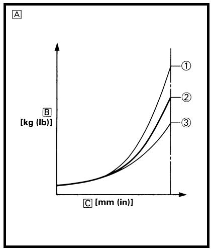
Air spring characteristics in relation to oil level change
Load
Stroke
① Max. oil level
(2) Standard oil level
③ Min. oil level
A Caracteristiques de I'amortissement pneumatique en fonction du niveau d'huile
Charge
C Course
① Niveau d'huile maximum
② Niveau d'huile standard
③ Niveau d'huile minimum
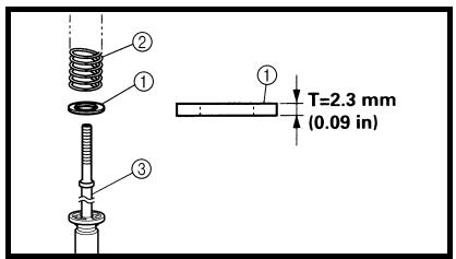
EC727020
Spring preload adjustmentg/staubig/locker/kurzgeschlossen Instand setzen, ggf. erneuern.
The spring preload is adjusted by installing the adjustment washer ① between the fork spring ② and damper rod ③.
CAUTION:">
Do not install three or more adjustment washers for each front fork.
WARNING
Always adjust each front fork to the same setting. Uneven adjustment can cause poor handling and loss of stability.

Standard washeratori e cavi Ruggine/polvere/lentezza/cortocircuito Riparare o sostuire.
quantity:
Zero adjustment washers
Extent of adjustment:
Zero ~ 2 adjustment washers
A Load
B Fork stroke
① Without adjustment washer (standard)
② 1 adjustment washer
③ 2 adjustment washers
Réglage de la précontraine du ressort
Le réglage de la précontraine du ressort se fait en montant la rondelle de réglage
① entre le ressort de fourche
② et la tige d'amortissement
③.
ATTENTION:de la bateria ① y el cable del motor de arranque ② con un puente ③ No funciona Repare o cambie el motor de arranque.
Ne pas monter trois rondelles d'ajustement ou plus pour chaque bras de fourche.
AVERTISSEMENTtener la misma o superior capacidad que el cable de la batería; de lo contrario, el puente se pueda quemar.
- Durante esta prueba es probable que se produzcan chispas; por lo tanto, compruebe que no haya nada inflamable en las proximidades.
Toujours régler de la même manière chaque bras de la fourche. Un niveau inégal risque de diminuer la maniability et la stabilité.

Nombre standard de rondelles:gang 12-V-Batterie verwenden.


|
En general, un muelle blanco da una sensacion de conducccion suave. La amortiguation en extension Tiende a endurecerse y la horquilla delantera peut hundirse profundamente afterwards de una series de vacios. Para ajustar un muelle blando:
Gire uno o doschasquidos hacia fauna.
Gire uno o dos chasquidos hacía bajo. 2. Uso de un muelle rigidod>En general, un muelle rígido da una sensación de conducccion dura. La amortiguación en extension tiene a debilitarse y, como consecuencia, se pierde sensación de contacto con el piso o el manillar vibra. Paraajustarunmuellerfigido:
Gire uno o doschasquidos hacia dentro.
Gire uno o doschasquidos hacia fauna.
Front fork setting partsh1>
|