
61SWX12B - Television HITACHI - Free user manual and instructions
Find the device manual for free 61SWX12B HITACHI in PDF.


| Product Type | Rear-projection television |
| Brand | Hitachi |
| Model | 61SWX12B |
| Screen Size | 61 inches (diagonal) |
| Aspect Ratio | 16:9 |
| Display Technology | CRT rear projection |
| Maximum Resolution | 1080i (1920x1080 interlaced) |
| Scan System | Progressive scan (480p, 720p, 1080i) |
| Dimensions (W x H x D) | 55.1 x 40.9 x 20.5 inches |
| Weight | 128 lbs (58 kg) |
| Power Consumption | 250 W (typical) |
| Inputs | Component video (Y, Pb, Pr), composite video, S-Video, RF antenna, VGA (PC input) |
| Audio Output | 10W x 2 stereo speakers, audio out (RCA) |
| Remote Control | Included (IR) |
| Built-in Tuner | NTSC (analog), ATSC (digital) |
| Picture-in-Picture | Yes (side-by-side or inset) |
| Cleaning Instructions | Use a soft, dry cloth; avoid liquid cleaners; clean screen with anti-static screen cleaner |
| Safety Features | Automatic shutdown after 15 minutes of no signal; anti-tip strap included |
| Spare Parts Availability | Replacement lamps, remote control, and main board available through authorized service centers |
| General Information | Designed for home entertainment; HDMI input may be added via external converter |
Frequently Asked Questions - 61SWX12B HITACHI
User questions about 61SWX12B HITACHI
0 question about this device. Answer the ones you know or ask your own.
Ask a new question about this device
Download the instructions for your Television in PDF format for free! Find your manual 61SWX12B - HITACHI and take your electronic device back in hand. On this page are published all the documents necessary for the use of your device. 61SWX12B by HITACHI.
USER MANUAL 61SWX12B HITACHI
IMPORTANT SAFETY INSTRUCTIONS 2-4
FIRST TIME USE 5-22
natural_image
Simple line drawing of a remote control with signal waves (no text or symbols)THE GENIUS REMOTE CONTROL 23-35

ULTRATEC BIT-MAP ON-SCREEN DISPLAY 36-70
USEFUL INFORMATION INDEX 71-75
Follow all warnings and instructions marked on this projection television.

WARNING
RISK OF ELECTRIC SHOCK DO NOT OPEN

CAUTION: TO REDUCE THE RISK OF ELECTRIC SHOCK, DO NOT REMOVE COVER (OR BACK).
NO USER SERVICEABLE PARTS INSIDE.
REFER SERVICING TO QUALIFIED SERVICE PERSONNEL.

The lightning flash with arrowhead symbol, within an equilateral triangle, is intended to alert the user to the presence of uninsulated "dangerous voltage" within the product's enclosure that may be of a sufficient magnitude to constitute a risk of electric shock to persons.

The exclamation point within an equilateral triangle, is intended to alert the user to the presence of important operating and maintenance (servicing) instructions in the literature accompanying the appliance.
WARNING:
TO REDUCE THE RISK OF FIRE OR ELECTRIC SHOCK, DO NOT EXPOSE THIS APPARATUS TO RAIN OR MOISTURE.
NOTE: • There are no user serviceable parts inside the television.
- Model and serial numbers are indicated on back side of the television.
- This television is not intended for use in a computer room.
CAUTION: Adjust only those controls that are covered in the instructions, as improper changes or modifications not expressly approved by HITACHI could void the user's warranty.
MODIFICATIONS:
The FCC requires the user to be notified that any changes or modifications made to this device that are not expressly approved by Hitachi America, Ltd. Home Electronics Division may void the user's warranty.
POWER SOURCE
This projection television is designed to operate on 120 Volts 60Hz, AC current. Insert power cord into a 120 Volt 60Hz outlet.
TO PREVENT ELECTRIC SHOCK, DO NOT USE THE TELEVISION'S (POLARIZED) PLUG WITH AN EXTENSION CORD, RECEPTACLE, OR OTHER OUTLET UNLESS THE BLADES AND GROUND TERMINAL CAN BE FULLY INSERTED TO PREVENT BLADE EXPOSURE.
NEVER CONNECT THE TELEVISION TO 50HZ, DIRECT CURRENT, OR ANYTHING OTHER THAN THE SPECIFIED VOLTAGE.
NOTE: This television receiver will display television closed captioning, (CC or □), in accordance with paragraph 15.119 of the FCC rules.

CAUTION: Never remove the back cover of the television as this can expose you to very high voltages and other hazards. If the television does not operate properly, unplug the television and call your authorized dealer or service shop.
IMPORTANT SAFETY INSTRUCTIONS
CAUTION:
- Read these instructions.
SAFETY POINTS YOU SHOULD KNOW ABOUT
- Keep these instructions. YOUR HITACHI PROJECTION TELEVISION
- Heed all warnings.
- Follow all instructions.
Our reputation has been built on the quality, performance, and ease of service of HITACHI televisions.
Safety is also foremost in our minds in the design of these units. To help you operate these products properly, this section illustrates safety tips which will be of benefit to you. Please read it carefully and apply the knowledge you obtain from it to the proper operation of your HITACHI television.
Please fill out your warranty card and mail it to HITACHI. This will enable HITACHI to notify you promptly in the improbable event that a safety problem should be discovered in your product model.
FOR YOUR PERSONAL SAFETY
-
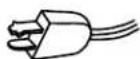
Do not defeat the safety purpose of the polarized or grounding-type plug. A polarized plug has two blades with one wider than the other. A grounding type plug has two blades and a third grounding prong. The wide blade or the third prong are provided for your safety. If the provided plug does not fit into your outlet, consult an electrician for replacement of the obsolete outlet.
-
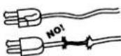
When the power cord or plug is damaged or frayed, unplug the television from the wall outlet and refer servicing to qualified service personnel.
-
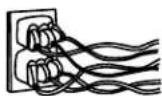
Do not overload wall outlets and extension cords as this can result in fire or electric shock.
-
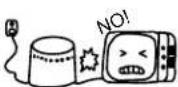
Protect the power cord from being walked on or pinched particularly at plugs, convenience receptacles, and the point where they exit from the apparatus.
- Do not attempt to service the television yourself as opening or removing covers may expose you to dangerous voltage or other hazards. Refer all servicing to qualified service personnel.
- Never push objects of any kind into the television's cabinet slots as they may touch dangerous voltage points or short out parts that could result in a fire or electric shock. Never spill liquid of any kind on the television.
- If the television has been dropped or the cabinet has been damaged, unplug the television from the wall outlet and refer servicing to qualified service personnel.
- Refer all servicing to qualified service personnel. Servicing is required when the apparatus has been damaged in any way, such as power-supply cord or plug is damaged, liquid has been spilled or objects have fallen into the apparatus, the apparatus has been exposed to rain or moisture, does not cooperate normally, or has been dropped.
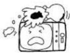
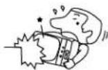
- Do not subject your television to impact of any kind. Be careful not to damage the picture tube surface.
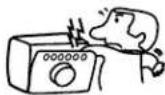
10. Clean only with dry cloth
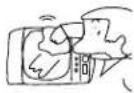
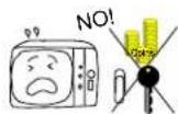
11-1. Do not place the television on an unstable cart, stand, or table. The television may fall, causing serious injury to a child or an adult, and serious damage to the appliance. Use only with a cart or stand recommended by the manufacturer, or sold with the television. Wall or shelf mounting should follow the manufacturer's instructions, and should use a mounting kit approved by the manufacturer.

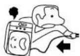
11-2. Use only with the cart, stand, tripod, bracket, or table specified by the manufacturer, or sold with the apparatus. When a cart is used, use caution when moving the cart/apparatus combination to avoid injury from tip-over.

PROTECTION AND LOCATION OF YOUR TELEVISION
- Do not use this apparatus near water.
- Never expose the television to rain or water. If the set has been exposed to rain or water, unplug television from wall outlet and refer to qualified service personnel.
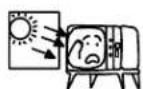
- Choose a place where light (artificial or sunlight) does not shine directly on the screen.
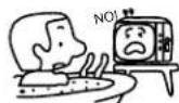
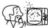
- Avoid dusty places. Accumulated dust inside the chassis may cause failure of the television when high humidity persists.
- The television has slots or openings in the cabinet for ventilation purposes which provide reliable operation of the receiver and protect the television from overheating. These openings must not be blocked or covered.
- Do not block any ventilation openings. Install in accordance with the manufacturer's instructions.
- Never cover the slots or openings with cloth or other material.
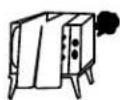
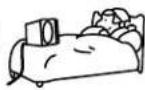
- Never block the bottom ventilation slots of the television by placing it on a bed, sofa, rug, etc.
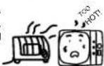
- Do not install near any heat sources such as radiators, heat registers, stoves, or other apparatus (including amplifiers) that produce heat.
- Never place the television near or over a radiator or heat generator.
- Never place the television in a built-in enclosure unless proper ventilation is provided.

PROTECTION AND LOCATION OF YOUR TELEVISION
16-1. If an outside antenna is connected to the television, be sure the antenna system is grounded so as to provide some protection against voltage surges and built-up static charges. Section 810 of the National Electrical Code, NFPA No. 70-1975, provides information with respect to proper grounding of the mast and supporting structure, grounding of the lead-in wire to an antenna discharge unit, size of grounding conductors, location of antenna discharge unit connection to grounding electrode, and requirements for the grounding electrode.
16-2. Note to CATV system installer: (Only for television with CATV reception). This reminder is provided to call the CATV system installer's attention to Article 820-40 of the NEC that provides guidelines for proper grounding and, in particular, specifies that the cable ground shall be connected to the grounding system of the building, as close to the point of cable entry as practical.
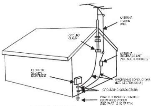
NEC NATIONAL ELECTRICAL CODE
EXAMPLE OF ANTENNA GROUNDING AS PER NATIONAL ELECTRICAL CODE INSTRUCTIONS.
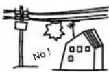
- An outside antenna system should not be located in the vicinity of overhead power lines or other electrical lights or power circuits, or where it can fall into such power lines or circuits. When installing an outside antenna system, extreme care should be taken to keep from touching such power lines or circuits as contact with them might be fatal.
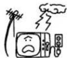
- For added protection for the television during a lightning storm, or when it is unused for long periods of time, unplug it from the wall outlet and disconnect antenna. This will prevent damage due to lightning and power-line surges.
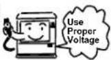
- This television should be operated only from the type of power source indicated on the marking label. If you are not sure of the type of power supply at your home, consult your dealer or local power company.
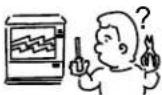
- If the television does not operate normally by following the operating instructions, unplug the television from the wall outlet and refer servicing to qualified service personnel. Adjust only those controls that are covered in the instructions as improper adjustment of other controls may result in damage and will often require extensive work by a qualified service technician to restore the television to normal operation.
- If your television is to remain unused for a period of time, (such as when going on a holiday), turn the television OFF and unplug it from the wall outlet.
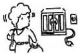
IF THE TELEVISION DOES NOT OPERATE PROPERLY
- If you are unable to restore normal operation by following the detailed procedure in your operating instructions, do not attempt any further adjustments. Unplug the television and call your dealer or service technician.

-
Whenever the television is damaged or fails, or if there is a distinct change in performance that indicates a need for service, unplug the television and have it checked by a qualified service technician.
-
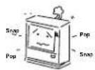
It is normal for some televisions to make occasional snapping or popping sounds, particularly when being turned on or off. If the snapping or popping is continuous or frequent, unplug the set and consult your dealer or service technician.
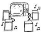
FOR SERVICING AND MODIFICATION
- Do not use attachments not recommended by the television manufacturer as they may cause hazards.
-
If replacement parts are required, be sure the service technician has used replacement parts specified by the manufacturer that have the same characteristics as the original part. Unauthorized substitutions may result in fire, electric shock, or other hazards.
-
Upon completion of any service or repairs to the television, ask the service technician to perform routine safety checks to determine that the television is in safe operating condition.

PICTURE CAUTIONS
Picture Burn Prevention
- Continuous on-screen displays such as video games, stock market quotations, computer generated graphics, and other fixed (non-moving) patterns can cause permanent damage to projection television receivers. Such “PATTERN BURNS” constitute misuse and are NOT COVERED by your HITACHI Factory Warranty.
- When using Picture-in-Picture function, the sub-picture should not be left permanently in one corner of the screen or a "PATTERN BURN" may develop over a long period of time.
Public Viewing of Copyrighted Material
Public viewing of programs broadcast by TV stations and cable companies, as well as programs from other sources, may require prior authorization from the broadcaster or owner of the video program material.
Check to make sure you have the following accessories before disposing of the packing material.
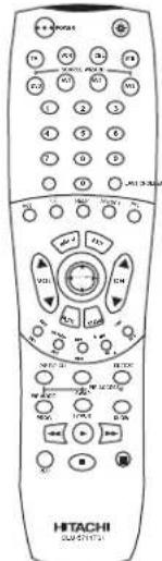 CLU-5711TSI 1. CLU-5711TSI 1. | 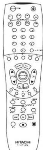 CLU-5713TSI 1. CLU-5713TSI 1. | 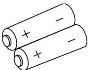 2. 2. | ||
| PART NAME | PART NO. ILLU | STRATION | ||
| 43" TELEVISION STANDSP-43W(Not included,order separately)OPTIONAL | H530052 | |||
| CUSTOM HITACHI TELEVISION STANDExcellent for VCR and video-tape storage.Special features include smoked glass doorsand an adjustable shelf. Available in shark grey. | ||||

CAUTION: Television stand model SP-43W is designed for use with a 43 inch or smaller television set. Use of a smaller stand, a non Hitachi recommended stand or a generic stand may result in instability, causing possible injury.
- Remote Control Unit CLU-5711TSI (Part No. HL01641), or Remote Control Unit CLU-5713TSI (Part No. HL01643).
- Two "AA" size, 1.5V batteries (For Remote Control Unit).
REMOTE CONTROL BATTERY INSTALLATION AND REPLACEMENT
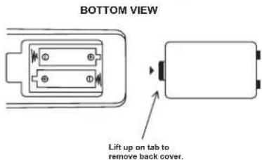
- Open the battery cover of the remote control by pushing the notched part of the cover with your fingers and pulling the cover off.
- Insert two new "AA" size batteries for the remote control. When replacing old batteries, push them towards the springs and lift them out.
-
Match the batteries to the (+) and (-) marks in the battery compartment.
-
Replace the cover.

CAUTION: Danger of explosion if battery is incorrectly replaced. Replace with the same or equivalent type.
ANTENNA
Unless your TV is connected to a cable TV system or to a centralized antenna system, a good outdoor color TV antenna is recommended for best performance. However, if you are located in an exceptionally good signal area that is free from interference and multiple image ghosts, an indoor antenna may be sufficient.
LOCATION
Select an area where sunlight or bright indoor illumination will not fall directly on the picture screen. Also, be sure that the location selected allows a free flow of air to and from the perforated back cover of the set.
To avoid cabinet warping, cabinet color changes, and increased chance of set failure, do not place the TV where temperatures can become excessively hot, for example, in direct sunlight or near a heating appliance, etc.
VIEWING
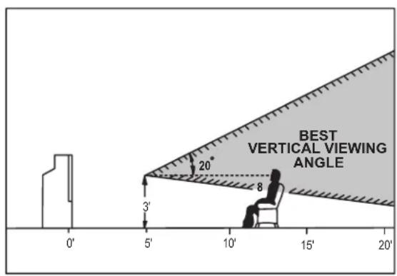
The major benefit of the HITACHI Projection Television is its large viewing screen. To see this large screen at its best, test various locations in the room to find the optimum spot for viewing.
The best picture is seen by sitting directly in front of the TV and about 10 to 18 feet from the screen. Picture brightness decreases as the viewer moves to the left and right of the receiver.
During daylight hours, reflections from outside light may appear on the screen. If so, drapes or screens can be used to reduce the reflection or the TV can be located in a different section of the room.
If the TV's audio output will be connected to a Hi-Fi system's external speakers, the best audio performance will be obtained by placing the speakers equidistant from each side of the receiver cabinet and as close as possible to the height of the picture screen center. For best stereo separation, place the external speakers at least four feet from the side of the TV, place the surround speakers to the side or behind the viewing area. Differences in room sizes and acoustical environments will require some experimentation with speaker placement for best performance.
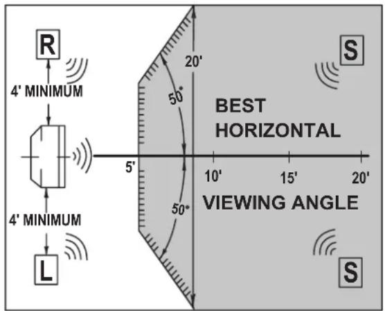

CAUTION: Magnetic fields, such as those of external speakers, may cause the picture to distort if they are placed too close to the television. Move the magnetic field source away from the television until there is no picture distortion.
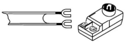
Most video/audio connections between components can be made with shielded video and audio cables that have phono connectors. For best performance, video cables should use 75-Ohm coaxial shielded wire. Cables can be purchased from most stores that sell audio/video products. Below are illustrations and names of common connectors. Before purchasing any cables, be sure of the output and input connector types required by the various components and the length of each cable.
natural_image
Technical line drawing of a U-shaped connector and its corresponding electrical terminal block (no text or symbols)300-Ohm Twin Lead Connector
This outdoor antenna cable must be connected to an antenna adapter (300-Ohm to 75-Ohm).
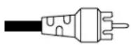
Phono Connector
Used on all standard video and audio cables which connect to inputs and outputs located on the television's rear jack panel and front control panel.

"F" Type 75-Ohm Coaxial Antenna Connector
For connecting RF signals (antenna or cable TV) to the antenna jack on the television.

S-VIDEO (Super Video) Connector
This connector is used on camcorders, VCRs, and laserdisc players with an S-VIDEO feature in place of the standard video cable to produce a high quality picture.
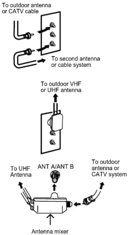
ANTENNA CONNECTIONS TO REAR JACK PANEL
VHF (75-Ohm) antenna/CATV (Cable TV)
When using a 75-Ohm coaxial cable system, connect the outdoor antenna or CATV coaxial cable to the ANT A (75-Ohm) terminal. If you have a second antenna or cable TV system, connect the coaxial cable to the ANT B terminal.
VHF (300-Ohm) antenna/UHF antenna
When using a 300-Ohm twin lead from an outdoor antenna, connect the VHF or UHF antenna leads to screws of the VHF or UHF adapter. Plug the adapter into the antenna terminal on the TV.
When both VHF and UHF antennas are connected
Attach an optional antenna cable mixer to the TV antenna terminal, and connect the cables to the antenna mixer. Consult your dealer or service store for the antenna mixer.
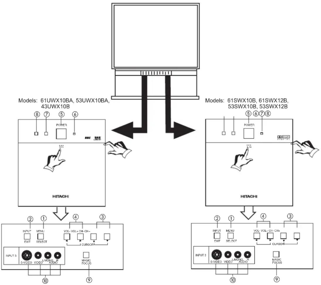
FRONT VIEW
flowchart
graph TD
    A["Model 61UWX10BA, 53UWX10BA, 43UWX10B"] --> B["POWER"]
    B --> C["SRS LNDU"]
    C --> D["INPUT 3 S-VIDEO VIDEO L-MOCO R AUDIO MAGIC FOCUS"]
    D --> E["INPUT 2 MENU EXIT SELECT VOL-VOL+CH- CURSOR"]
    E --> F["①"]
    F --> G["②"]
    G --> H["③"]
    H --> I["④"]
    I --> J["⑤"]
    J --> K["⑥"]
    K --> L["⑦"]
    L --> M["⑧"]
    M --> N["⑨"]
    N --> O["⑩"]
    O --> P["⑪"]
    P --> Q["⑫"]
    Q --> R["⑬"]
    R --> S["⑭"]
    S --> T["⑮"]
    T --> U["⑯"]
    U --> V["⑰"]
    V --> W["⑱"]
    W --> X["⑲"]
    X --> Y["⑳"]
    Y --> Z["⑴"]
    Z --> AA["⑫"]
    AA --> AB["⑬"]
    AB --> AC["⑭"]
    AC --> AD["⑮"]
    AD --> AE["⑯"]
① MENU/SELECT button
This button allows you to enter the MENU, making it possible to set TV features to your preference without using the remote. This button also serves as the SELECT button when in MENU mode.
② INPUT/EXIT button
Press this button to select the current antenna source, VIDEO: 1, 2, 3, 4, 5 or alternate antenna source. Your selection is shown in the top right corner of the screen. This button also serves as the EXIT button when in MENU mode.
NOTES: Your remote control does not have an INPUT button. To change to video inputs, press VID1\~VID5 buttons depending on your choice (see page 23).
③ CHANNEL selector
Press these buttons until the desired channel appears in the top right corner of the TV screen. These buttons also serve as the cursor down (▼) and up (▲) buttons when in MENU mode.
④ VOLUME level
Press these buttons for your desired sound level. The volume level will be displayed on the TV screen. These buttons also serve as the cursor left (◀) and right (▶) buttons when in MENU mode.
⑤ POWER button
Press this button to turn the TV on or off.
⑥ POWER light
You will see a red light when the TV is turned on.
⑦ PERFECT PICTURE sensor
The Perfect Picture sensor will make automatic picture adjustments depending on the amount of light in the room to give the best picture. (see page 57)
⑧ REMOTE CONTROL sensor
Point your remote at this area when selecting channels, adjusting volume, etc.
⑨ MAGIC FOCUS
Use this button to adjust your picture quality to optimum performance.
⑩ FRONT INPUT JACKS (for VIDEO: 3)
Use these audio/video jacks for a quick hook-up from a camcorder or VCR to instantly view your favorite show or new recording. Press the INPUT button until VIDEO: 3 appears in the top right corner of the TV screen. If you have mono sound, insert the audio cable into the left audio jack.
NOTES: 1. Your HITACHI Projection TV will appear to be turned OFF if there is no video input when VIDEO: 1, 2, 3, 4 or 5 is selected. Check the Power Light to make sure the TV is turned off when not in use.
2. To see an auto-demonstration of the on-screen displays with HELP text displayed, press and hold the POWER button on the TV set for approximately five seconds. Press the POWER button on the TV again to end the auto-demonstration.
The front panel jacks are provided as a convenience to allow you to easily connect a camcorder or VCR as shown in the following examples:
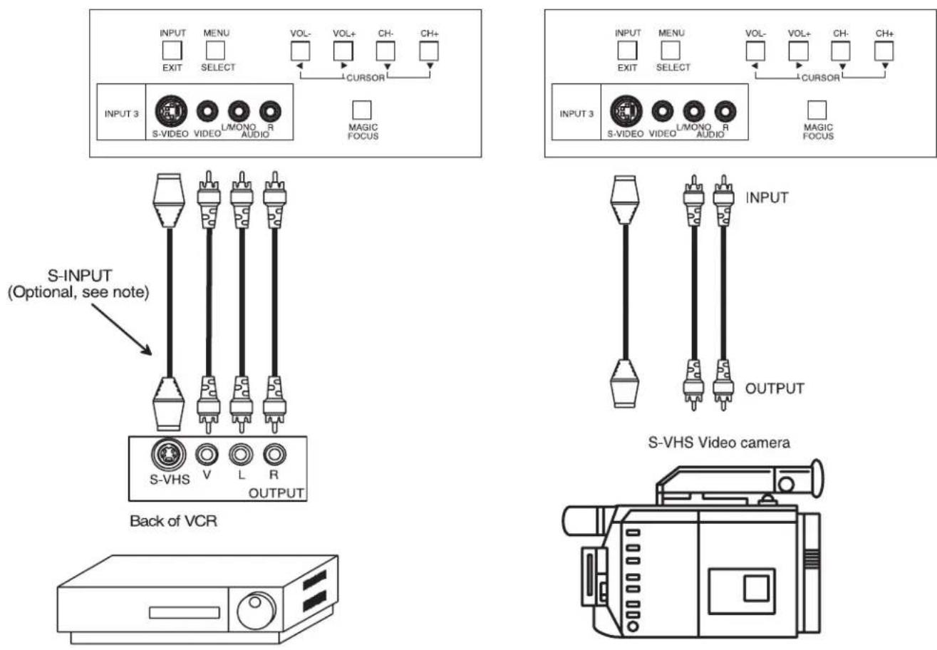
NOTE: 1. Completely insert connection cord plugs when connecting to front panel jacks. If you do not, the played back picture may be abnormal.
2. If you have a S-VHS VCR, use the S-INPUT cable in place of the standard video cable.
3. If you have a mono VCR, insert the audio cable into the left audio jack of your TV.
Models: 61UWX10BA, 53UWX10BA, 43UWX10B
flowchart
graph TD
    A["OUTPUT 1"] --> B["S-MODES"]
    C["INPUT 2"] --> D["VIDEO"]
    E["INPUT 4"] --> F["VIDEO"]
    G["INPUT 5"] --> H["Y-VIDEO"]
    I["MONITOR OUT"] --> J["S-VIDEO"]
    K["TO CONVERTER"] --> L["AVT A"]
    M["AUDIO TO HI-FI"] --> N["R L"]
    O["AVT B"] --> P["AVT B"]
    Q["AVT A"] --> R["AVT A"]
    S["AVT B"] --> T["AVT B"]
    U["AVT A"] --> V["AVT A"]
    W["AVT B"] --> X["AVT B"]
    Y["AVT A"] --> Z["AVT A"]
    AA["AVT B"] --> AB["AVT B"]
    AC["AVT A"] --> AD["AVT A"]
    AE["AVT B"] --> AF["AVT B"]
    AG["AVT A"] --> AH["AVT A"]
    AI["AVT B"] --> AJ["AVT B"]
    AK["AVT A"] --> AL["AVT A"]
    AM["AVT B"] --> AN["AVT B"]
    AO["AVT A"] --> AP["AVT A"]
    AQ["AVT B"] --> AR["AVT B"]
    AS["AVT A"] --> AT["AVT A"]
    AU["AVT B"] --> AV["AVT B"]
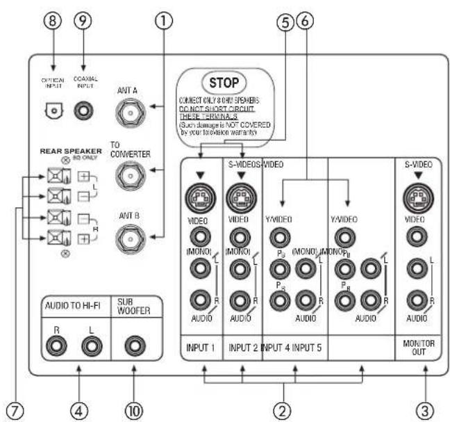
① Antenna Input/Output
The remote control allows you to switch between two separate 75-Ohm RF antenna inputs, ANT A and ANT B. ANT A input can be displayed as a main picture or sub-picture. ANT B can only be displayed as a main picture. (ANT B cannot be displayed as a sub-picture.) The antenna output labeled "TO CONVERTER" allows the ANT A connection to pass directly to a different source such as a cable box, only when ANT B is displayed as a main picture.
② Audio/Video Inputs 1, 2, 4 and 5
The VID1\~VID5 buttons will select each video source each time they are pressed. Use the audio and video inputs to connect external devices, such as VCRs, camcorders, laserdisc players, DVD players etc. (If you have mono sound, insert the audio cable into the left audio jack.)
NOTE: You may use VIDEO or S-VIDEO inputs to connect to INPUT 1 and 2, but only one of these inputs may be used at a time.
③ MONITOR OUT
These jacks provide fixed audio and video signals which are used for recording. Use the S-VIDEO Output for high quality video output.
NOTE: S-VIDEO Output may be used for recording, only when the input is of S-VIDEO type.
④ AUDIO TO HI-FI Output
These jacks provide variable audio output to a separate stereo amplifier. With this connection, the audio to the stereo can be controlled by the television's main volume.
⑤ S-VIDEO Inputs 1 and 2
Inputs 1 and 2 provide S-VIDEO (Super Video) jacks for connecting equipment with S-VIDEO output capability.
⑥ Component: Y-P _B P _R Inputs
Inputs 4 and 5 provide Y- P_BP_R jacks for connecting equipment with this capability, such as a DVD player or Set Top Box. You may use standard video signal for INPUT:4 and 5.
Items ⑦ \~ ⑩ are for 53/61SWX10B and 53/61SWX12B only.
⑦ REAR SPEAKER Output Terminals
These terminals are used to connect external speakers, which are used for the surround sound feature. The volume level is controlled by the television's main volume. These speaker output terminals can be turned on and off in the THEATER-SPEAKER SETUP menu. Use speakers with 8-Ohm impedance only.
⑧ Optical Input
This jack provides high quality audio input from a Dolby Digital DVD player or HDTV Set Top Box. Use a digital optical cable to connect your TV to a compatible device. This input can be used for VIDEO: 4 or VIDEO: 5 audio, as selected in the THEATER-INPUT SOURCE menu. (see page 68)
⑨ Coaxial Input
This jack provides high quality audio input from a Dolby Digital DVD player or HDTV Set Top Box. This input can be used for VIDEO: 4 or VIDEO: 5 audio, as selected in the THEATER-INPUT SOURCE menu. (see page 68)
⑩ SUB WOOFER Output
This jack provides variable audio output to a sub-woofer accessory. With this connection, the audio can be controlled by the television's main volume. This feature can be turned on and off in the THEATER-SPEAKER SETUP menu.
NOTES: 1. DO NOT connect standard VIDEO and S-VIDEO to Input 1, 2 or 3 at the same time. S-Video has a higher priority over video input.
- When using the Y-P B P R input jacks, connect your components audio output to the TV's Input 4 or 5 Left and Right Audio input jacks. If your component has a Coaxial Out or Optical Out, use these connectors in place of the standard Audio L/R output jacks.
- Your component outputs may be labeled Y, B-Y, and R-Y. In this case, connect the components B-Y output to the TV's P_B input and the components R-Y output to the TV's P_R input.
- Your component outputs may be labeled Y-C B C R . In this case, connect the component C B output to the TV's P B input and the component C R output to the TV's P R input.
- It may be necessary to adjust TINT to obtain optimum picture quality when using the Y-P B P R inputs. (See page 56)
- To ensure no copyright infringement, the MONITOR OUT output will be abnormal, when using the Y-P B P R jacks.
- This TV's optical digital input jack fully complies with the international standard governing this type of jack (IEC958), and is designed for connection to a Dolby Digital (AC-3 or PCM) DVD Player or Dolby Digital (AC-3 or PCM) HDTV Set Top Box. Older equipment, some of which is not fully compliant with IEC958, may not be compatible with the Dolby Digital bitstream. Such a connection using anything other than Dolby Digital AC-3 or PCM bitstream could create a high noise level, causing damage to your speakers.
TYPICAL FULL-FEATURE SETUP (43UWX10B and 53/61UWX10BA MODELS)
flowchart
graph TD
    A["Outside antenna or cable TV coaxial cable"] --> B["2-Way signal splitter"]
    B --> C["VCR #1"]
    B --> D["DVD Player"]
    C --> E["OUTPUT S-VIDEO V L R"]
    D --> F["OUTPUT Y Pn/Cb Rn/R L R"]
    E --> G["Optional, see tips on page 15"]
    F --> H["Optional, see tips on page 15"]
    I["Stereo System Amplifier"] --> J["INPUT L R"]
    J --> K["AUDIO TO HI-FI R L"]
    K --> L["OUTPUT INPUT 1"]
    K --> M["OUTPUT INPUT 2"]
    K --> N["OUTPUT INPUT 4 INPUT 5"]
    K --> O["OUTPUT OUTPUT"]
    P["Cable TV Box"] --> Q["Optional, see tips on page 15"]
    Q --> R["Laserdisc player, VCR, camcorder, etc."]
    S["HDTV Set-Top Box"] --> T["Y Pb PR L R"]
    U["STUDIO"] --> V["OUTPUT"]
    W["OUTPUT"] --> X["OUTPUT"]
    Y["OUTPUT"] --> Z["OUTPUT"]
NOTE:
- Connect only 1 component to each input jack.
- Follow connections that pertain to your personal entertainment system.
- Standard video signal (composite video) can be input to all video inputs. (Video 1 - Vldeo 5).
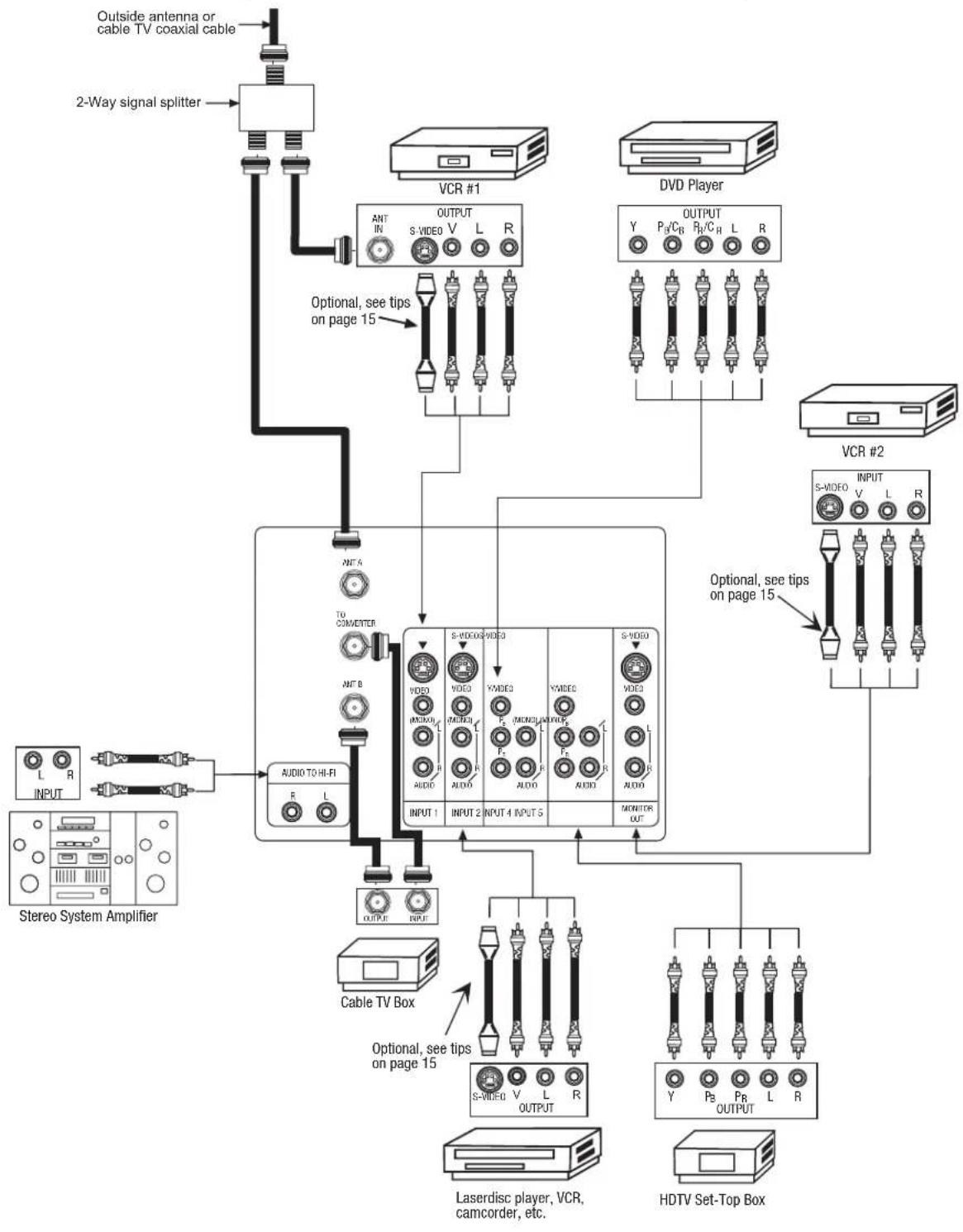
TYPICAL FULL-FEATURE SETUP
(53/61SWX10B AND 53/61SWX12B MODELS)
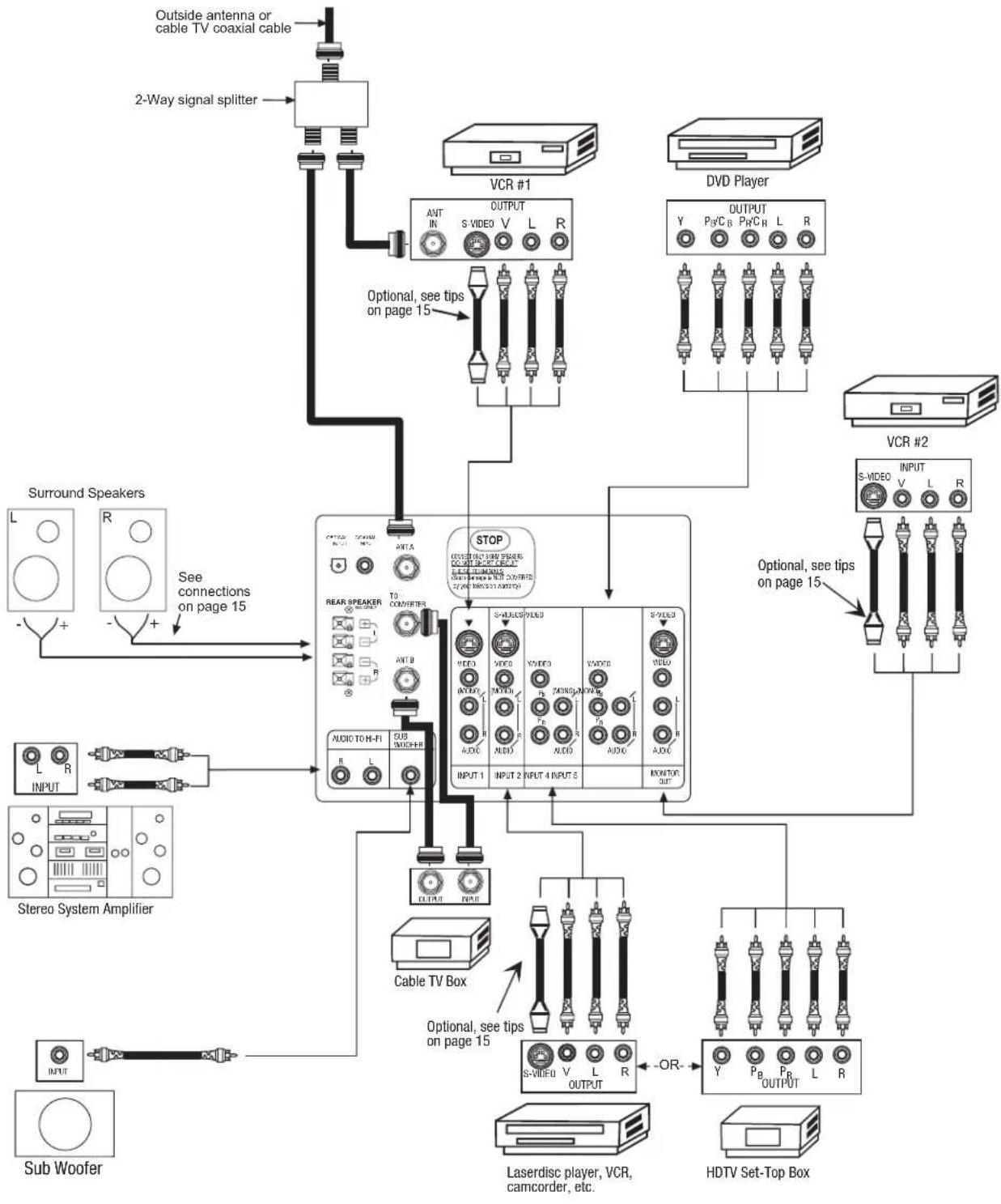
flowchart
graph TD
    A["Outside antenna or cable TV coaxial cable"] --> B["2-Way signal splitter"]
    B --> C["VCR #1"]
    C --> D["OUTPUT"]
    D --> E["AVT IN S VIDEO V L R"]
    E --> F["Optional, see tips on page 15"]
    F --> G["DVD Player"]
    G --> H["OUTPUT Y Pn/C B Pn/C R L R"]
    H --> I["VCR #2"]
    I --> J["INPUT S-VIDEO V L R"]
    J --> K["Optional, see tips on page 15"]
    K --> L["VCR #2"]
    L --> M["OUTPUT Y Pn/C B Pn/C R L R"]
    M --> N["Optional, see tips on page 15"]
    N --> O["VCR #2"]
    O --> P["OUTPUT Y Pn/C B Pn/C R L R"]
    P --> Q["Optional, see tips on page 15"]
    Q --> R["VCR #2"]
    R --> S["OUTPUT Y Pn/C B Pn/C R L R"]
    S --> T["Optional, see tips on page 15"]
    T --> U["VCR #2"]
    U --> V["OUTPUT Y Pn/C B Pn/C R L R"]
    V --> W["Optional, see tips on page 15"]
    W --> X["VCR #2"]
    X --> Y["OUTPUT Y Pn/C B Pn/C R L R"]
    Y --> Z["Optional, see tips on page 15"]
    Z --> AA["VCR #2"]
    AA --> AB["OUTPUT Y Pn/C B Pn/C R L R"]
    AB --> AC["Optional, see tips on page 15"]
    AC --> AD["VCR #2"]
    AD --> AE["OUTPUT Y Pn/C B Pn/C R L R"]
    AE --> AF["Optional, see tips on page 15"]
    AF --> AG["VCR #2"]
    AG --> AH["OUTPUT Y Pn/C B Pn/C R L R"]
    AH --> AI["Optional, see tips on page 15"]
    AI --> AJ["VCR #2"]
    AJ --> AK["OUTPUT Y Pn/C B Pn/C R L R"]
    AK --> AL["Optional, see tips on page 15"]
NOTE:
- Connect only 1 component to each input jack.
- Follow connections that pertain to your personal entertainment system.
- Standard video signal (composite video) can be input to all video inputs. (Video 1 \~ Video 5).
CONNECT AFTER TURNING THE POWER TO THE TV OFF.
(Rear speaker connection applies to SWX model only)
Press the Right Speaker red button and insert the positive (+) lead wire into the hole next to the button. Once the wire is in place, pull the red button back to original position and the wire is locked into place. In the same manner, press the Right Speaker black button and insert the negative (-) lead wire. Repeat this procedure for the Left Speaker.

CAUTION: Do not short speaker terminal, (do not connect a wire directly across any two terminals). This could cause damage to your audio outputs or other damage to your TV.
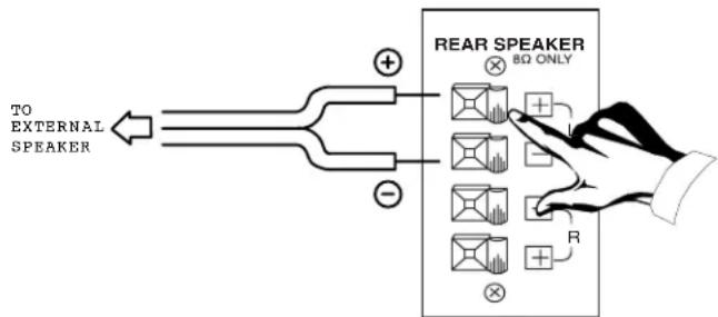

CAUTION: Do not connect speakers simultaneously to the REAR SPEAKER terminal of the Projection TV and an external amplifier. This could damage both the TV and the speakers. Your TV was designed to use 8-Ohm speakers only. Any other type may degrade the audio performance of your entertainment system.
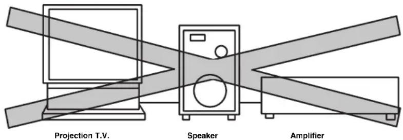
TIPS ON REAR PANEL CONNECTIONS
S-VIDEO connections are provided for high performance laserdisc players, VCRs etc. that have this feature. Use these connections in place of the standard video connection if your device has this feature.
If your device has only one audio output (mono sound), connect it to the left audio jack on the television.
Refer to the operating guide of your other electronic equipment for additional information on connecting your hook-up cables.
A single VCR can be used for VCR #1 and VCR #2, but note that a VCR cannot record its own video or line output (INPUT: 1 in the example on page 13 or 14). Refer to your VCR operating guide for more information on line input-output connections.
You may use VIDEO or S-VIDEO inputs to connect to Input 1 or Input 2, but only one of these may be used at a time.
Connect only 1 component (VCR, DVD player, camcorder, etc.) to each input jack.
COMPONENT: Y-R B P R (Input 4 &5) connections are provided for high performance components, such as DVD players and set-top-boxes. Use these connections in place of the standard video connection if your device has this feature.
Your component outputs may be labeled Y, B-Y, and R-Y. In this case, connect the components B-Y output to the TV's P_B input and the components R-Y output to the TV's P_R input.
Your component outputs may be labeled Y-C B C R . In this case, connect the components C B output to the TV's P B input and the components C R output to the TV's P R input.
You may use standard video signal for INPUT:4 and 5.
It may be necessary to adjust TINT to obtain optimum picture quality when using the Y- P_BP_R inputs. (See page 56)
To ensure no copyright infringement, the MONITOR OUT output will be abnormal, when using the Y-PBPR jacks.
CONNECTING EXTERNAL AUDIO AMPLIFIER
To control the audio level of an external audio amplifier with the remote control, connect the system as shown below.
REAR PANEL OF TELEVISION
Models: 61UWX10BA, 53UWX10BA, 43UWX10B
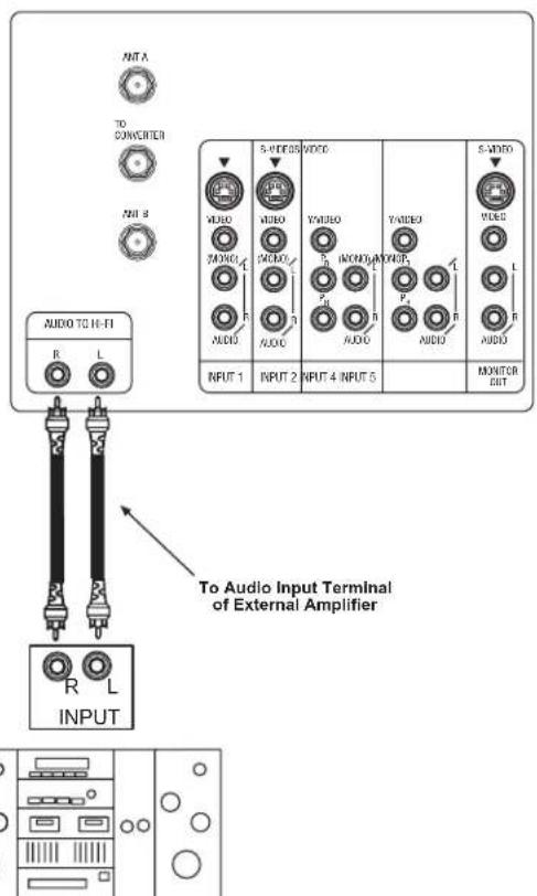
Stereo System Amplifier
NOTE: To prevent damage to the speaker and distorted sound, set the volume control of the audio amplifier lower and adjust the sound using the remote control of the TV set.
Match the numbers below to the diagrams for speaker placement and refer to the table on page 18 for the different surround sound requirements. (See pages 65-67 for SURROUND functions.)
① The television's internal speakers.
② The television's internal center channel speaker, which is on only when the television is in SURROUND-STADIUM, SURROUND-ROCK ARENA, SURROUND-JAZZ CLUB, SURROUND-PRO LOGIC, or SURROUND-DOLBY DIGITAL mode.
③ These speakers are connected to a separate audio amplifier. Use the AUDIO TO HI-FI output on the TV.
④ These speakers are connected to a rear speaker 8-Ohm output on the TV.
⑤ This sub woofer is connected to the SUB WOOFER output on the TV.
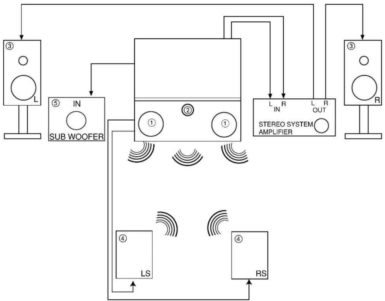
flowchart
graph TD
    A["③ L"] --> B["⑤ IN SUB WOOFER"]
    B --> C["①"]
    C --> D["②"]
    D --> E["①"]
    E --> F["L IN STEREO SYSTEM AMPLIFIER"]
    F --> G["L OUT"]
    G --> H["③ R"]
    I["④ LS"] --> J["④ RS"]
    K["④"] --> I
    style A fill:#f9f,stroke:#333
    style B fill:#ccf,stroke:#333
    style C fill:#cfc,stroke:#333
    style D fill:#fcc,stroke:#333
    style E fill:#cff,stroke:#333
    style F fill:#ffc,stroke:#333
    style G fill:#cfc,stroke:#333
    style H fill:#fcc,stroke:#333
    style I fill:#ffc,stroke:#333
    style J fill:#cfc,stroke:#333
    style K fill:#fcc,stroke:#333
| SURROUND REQU FEATURE | RED OPTIONAL EFFECT CONNECTION | CONNECTION | |
| OFF 1 | 3 | 5 | Receive mono and stereo sound. |
| STADIUM 1 2 4 | 3 5 Listener has | feeling of being at a | stadium. |
| ROCK ARENA | 1 2 4 | 3 5 | Listener has feeling of being at a rock concert. |
| JAZZ CLUB 1 2 4 | 3 5 Listener has | feeling of being at a | jazz club. |
| DOLBY PRO LOGIC center | 1 2 4 right, and surround | 3 5 channels. | Movie theater reproduction, with separate left, |
| DOLBY DIGITAL | 1 2 4 5 | 3 | To be used with a DVD player or HDTV Set Top Box with Dolby Digital output. This provides up to 6 channels of all-digital surround sound. There are 3 full-range channels for the front (FL, C, FR) plus separate, full-range left and right surround channels (SL, SR). The sixth channel is Low Frequency Effects for a sub woofer (SW), supplying those room-shaking rumbles experienced in the best movie theaters. |
When left and right speakers are connected (③), the internal speakers (①) can be disabled, creating better separation between left, center and right channels. The center channel audio will be heard from (②), this speaker cannot be disabled.
The exact arrangement you use to connect the VCR, camcorder, laserdisc player, DVD player, or HDTV Set Top Box to your TV set is dependent on the model and features of each component. Check the owner's manual of each component for the location of video and audio inputs and outputs.
The following connection diagrams are offered as suggestions. However, you may need to modify them to accommodate your particular assortment of components and features. For best performance, video and audio cables should be made from coaxial shielded wire.
Before Operating External Video Source
The input mode is changed every time the VID1\~VID5 button is pressed as shown below. Connect an external source to the INPUT terminal, then press the VID1\~VID5 button as necessary to view the input source. (See page 26)
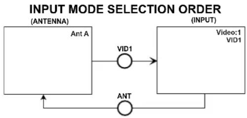
flowchart
graph TD
    A["Ant A\n(ANTENNA)"] --> B["VID1"]
    B --> C["Video:1\nVID1\n(INPUT)"]
    C --> D["ANT"]
    D --> A
NOTE: When the TV is set to VIDEO and a video signal is not received from the VIDEO INPUT JACK on the back panel of the TV (i.e., VCR/laserdisc player, etc. is not connected or the video device is OFF), the set will appear to be OFF.
CONNECTING A MONAURAL AUDIO SOURCE TO INPUT1\~INPUT5
- Connect the cable from the VIDEO OUT of the VCR or the laserdisc player to the INPUT (VIDEO) jack, as shown on the TV set below.
- Connect the cable from the AUDIO OUT of the VCR or the laserdisc player to the INPUT (MONO)/L(AUDIO) jack.
- Press the VID1\~VID5 button to view the program from the VCR or the laserdisc player. The VIDEO mode disappears automatically after approximately eight seconds.
- Press the ANT button to return to the previous channel.
Models: 61UWX10BA, 53UWX10BA, 43UWX10B
Models: 61SWX10B, 61SWX12B
53SWX10B, 53SWX12B
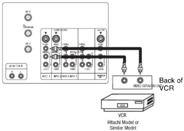
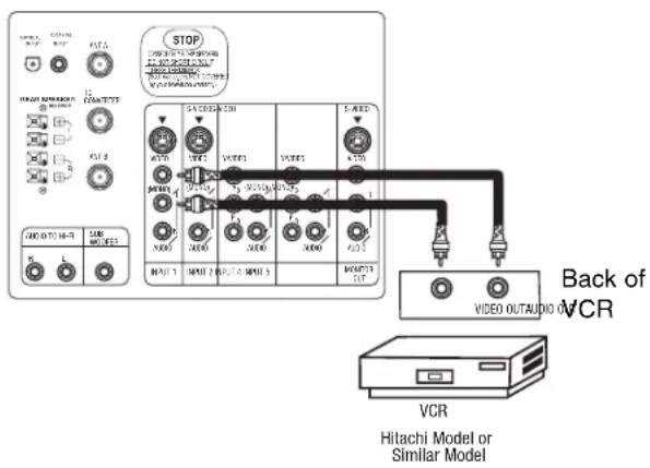
CONNECTING A STEREO SOURCE TO INPUT1\~INPUT5
- Connect the cable from the VIDEO OUT of the VCR or the laserdisc player to the INPUT (VIDEO) jack, as shown on the TV set below.
- Connect the cable from the AUDIO OUT R of the VCR or the laserdisc player to the INPUT (AUDIO/R) jack.
- Connect the cable from the AUDIO OUT L of the VCR or the laserdisc player to the INPUT (AUDIO/L) jack.
- Press the VID1\~VID5 button to view the program from the VCR or laserdisc player. The VIDEO icon disappears automatically after approximately eight seconds.
- Press the ANT button to return to the previous channel.
Models: 61UWX10BA, 53UWX10BA, 43UWX10B
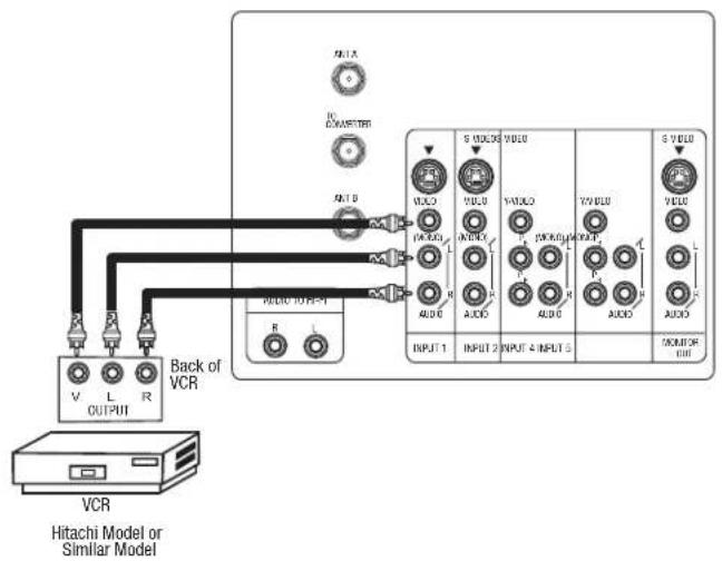
flowchart
graph TD
    A["VCR"] --> B["Back of VCR"]
    B --> C["VOUT/INT"]
    C --> D["ANDR"]
    D --> E["ANDR"]
    E --> F["ANDR"]
    F --> G["ANDR"]
    G --> H["ANDR"]
    H --> I["ANDR"]
    I --> J["ANDR"]
    J --> K["ANDR"]
    K --> L["ANDR"]
    L --> M["ANDR"]
    M --> N["ANDR"]
    N --> O["ANDR"]
    O --> P["ANDR"]
    P --> Q["ANDR"]
    Q --> R["ANDR"]
    R --> S["ANDR"]
    S --> T["ANDR"]
    T --> U["ANDR"]
    U --> V["ANDR"]
    V --> W["ANDR"]
    W --> X["ANDR"]
    X --> Y["ANDR"]
    Y --> Z["ANDR"]
    Z --> AA["ANDR"]
    AA --> AB["ANDR"]
    AB --> AC["ANDR"]
    AC --> AD["ANDR"]
    AD --> AE["ANDR"]
    AE --> AF["ANDR"]
    AF --> AG["ANDR"]
    AG --> AH["ANDR"]
    AH --> AI["ANDR"]
    AI --> AJ["ANDR"]
    AJ --> AK["ANDR"]
    AK --> AL["ANDR"]
    AL --> AM["ANDR"]
    AM --> AN["ANDR"]
    AN --> AO["ANDR"]
    AO --> AP["ANDR"]
    AP --> AQ["ANDR"]
    AQ --> AR["ANDR"]
    AR --> AS["ANDR"]
    AS --> AT["ANDR"]
    AT --> AU["ANDR"]
    AU --> AV["ANDR"]
    AV --> AW["ANDR"]
    AW --> AX["ANDR"]
    AX --> AY["ANDR"]
    AY --> AZ["ANDR"]
    AZ --> BA["ANDR"]
    BA --> BB["ANDR"]
    BB --> BC["ANDR"]
    BC --> BD["ANDR"]
    BD --> BE["ANDR"]
    BE --> BF["ANDR"]
    BF --> BG["ANDR"]
    BG --> BH["ANDR"]
    BH --> BI["ANDR"]
    BI --> BJ["ANDR"]
    BJ --> BK["ANDR"]
    BK --> BL["ANDR"]
    BL --> BM["ANDR"]
    BM --> BN["ANDR"]
    BN --> BO["ANDR"]
    BO --> BP["ANDR"]
    BP --> BQ["ANDR"]
    BQ --> BR["ANDR"]
    BR --> BS["ANDR"]
    BS --> BT["ANDR"]
    BT --> BU["ANDR"]
    BU --> BV["ANDR"]
    BV --> BW["ANDR"]
    BW --> BX["ANDR"]
    BX --> BY["ANDR"]
    BY --> BZ["ANDR"]
NOTES: 1. Completely insert the connection cord plugs when connecting to rear panel jacks. The picture and sound that is played back will be abnormal if the connection is loose.
2. A single VCR can be used for VCR #1 and VCR #2, but note that a VCR cannot record its own video or line output. (INPUT: 1 in example on page 13 or 14) Refer to your VCR operating guide for more information on line input-output connections.
CONNECTING AN S-VIDEO SOURCE TO INPUT 1, 2 AND 3
- Connect the cable from the S-VIDEO OUT of the VCR or the laserdisc player to the INPUT (S-VIDEO) jack, as shown on the TV set below.
- Connect the cable from the AUDIO OUT R of the VCR or the laserdisc player to the INPUT (AUDIO/R) jack.
- Connect the cable from the AUDIO OUT L of the VCR or the laserdisc player to the INPUT (AUDIO/L) jack.
- Press the VID1\~VID3 button to view the program from the VCR or laserdisc player. The VIDEO icon disappears automatically after approximately eight seconds.
- Press the ANT button to return to the previous channel.
Models: 61UWX10BA, 53UWX10BA, 43UWX10B
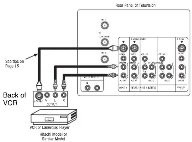
flowchart
graph TD
    A["Back of VCR"] --> B["VCR or Laserdisc Player"]
    B --> C["Hitachi Model or Similar Model"]
    C --> D["Back of VCR"]
    D --> E["See tips on Page 15"]
    E --> F["Back of VCR"]
    F --> G["View to Antenna"]
    G --> H["Antenna"]
    H --> I["Antenna"]
    I --> J["Antenna"]
    J --> K["Antenna"]
    K --> L["Antenna"]
    L --> M["Antenna"]
    M --> N["Antenna"]
    N --> O["Antenna"]
    O --> P["Antenna"]
    P --> Q["Antenna"]
    Q --> R["Antenna"]
    R --> S["Antenna"]
    S --> T["Antenna"]
    T --> U["Antenna"]
    U --> V["Antenna"]
    V --> W["Antenna"]
    W --> X["Antenna"]
    X --> Y["Antenna"]
    Y --> Z["Antenna"]
    Z --> AA["Antenna"]
    AA --> AB["Antenna"]
    AB --> AC["Antenna"]
    AC --> AD["Antenna"]
    AD --> AE["Antenna"]
    AE --> AF["Antenna"]
    AF --> AG["Antenna"]
    AG --> AH["Antenna"]
    AH --> AI["Antenna"]
    AI --> AJ["Antenna"]
    AJ --> AK["Antenna"]
    AK --> AL["Antenna"]
    AL --> AM["Antenna"]
    AM --> AN["Antenna"]
    AN --> AO["Antenna"]
    AO --> AP["Antenna"]
    AP --> AQ["Antenna"]
    AQ --> AR["Antenna"]
    AR --> AS["Antenna"]
    AS --> AT["Antenna"]
    AT --> AU["Antenna"]
    AU --> AV["Antenna"]
    AV --> AW["Antenna"]
    AW --> AX["Antenna"]
    AX --> AY["Antenna"]
NOTES:
- Completely insert the connection cord plugs when connecting to rear panel jacks. The picture and sound that is played back will be abnormal if the connection is loose.
- A single VCR can be used for VCR #1 and VCR #2, but note that a VCR cannot record its own video or line output. (INPUT: 1 in example on page 13 or 14) Refer to your VCR operating guide for more information on line input-output connections.
CONNECTING A COMPONENT SOURCE TO VIDEO 4 OR 5: Y-PBPR.
- Connect the cable from the Y OUT of the Laserdisc/DVD player or HDTV set top box to the INPUT (Y) jack, as shown on the TV set below.
- Connect the cable from the C B/PB OUT or B-Y OUT of the Laserdisc/DVD player or HDTV set top box to the INPUT ( P_B ) jack.
- Connect the cable from the C R/P_R OUT or R-Y OUT of the Laserdisc/DVD player or HDTV set top box to the INPUT ( P_R ) jack.
- Connect the cable from the AUDIO OUT R of the Laserdisc/DVD player or HDTV set top box to the INPUT (AUDIO/R) jack.
- Connect the cable from the AUDIO OUT L of the Laserdisc/DVD player or HDTV set top box to the INPUT (AUDIO/L) jack.
- Press the VID4\~VID5 button, to view the program from the Laserdisc/DVD player or HDTV set top box. The VIDEO icon disappears automatically after approximately eight seconds.
- Press the ANT button to return to the previous channel.
Models: 61UWX10BA, 53UWX10BA, 43UWX10B
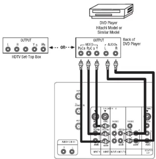
flowchart
graph TD
    A["HDTV Set-Top Box"] -->|OUTPUT| B["VIDEO"]
    A -->|OUTPUT| C["AUDIO"]
    A -->|OUTPUT| D["Back of DVD Player"]
    B --> E["Video"]
    C --> F["Audio"]
    D --> G["Back to DVD Player"]
    E --> H["OUTPUT 1"]
    F --> I["OUTPUT 2"]
    G --> J["OUTPUT 3"]
    H --> K["UNITS"]
    I --> L["UNITS"]
    J --> M["UNITS"]
    K --> N["UNITS"]
    L --> O["UNITS"]
    M --> P["UNITS"]
    N --> Q["UNITS"]
    O --> R["UNITS"]
Rear Panel of Television
Rear Panel of Television
NOTE: 1. You may use standard video signal for INPUT:4 and 5.
- Completely insert the connection cord plugs when connecting to rear panel jacks. The picture and sound that is played back will be abnormal if the connection is loose.
- See page 15 for tips on REAR PANEL CONNECTIONS.
- If your device is connected to INPUT 4 component jacks, make sure to select VID4-OPTICAL from the THEATER-INPUT SOURCE menu. If it is connected to INPUT 5 component jacks, make sure to select VID5-OPTICAL from the THEATER-INPUT SOURCE menu.
In addition to controlling all the functions on your HITACHI Projection TV, the new remote control is designed to operate different types of VCRs, CATV (Cable TV) converters, set-top-box, satellite receiver, DVD players, and other audio/video equipment with one touch. Basic operation keys are grouped together in one area.
To operate your TV, point the remote control at the remote sensor of the TV and press the TV button. The TV button will blink, indicating that the remote will now control your television.
To operate your VCR, point the remote at the remote sensor of the VCR and press the VCR button. The VCR button will blink, indicating that the remote will now control your VCR. (See page 30 for instructions on how to program the remote to control your VCR.)
To operate your cable box, point the remote at the remote sensor of the cable box and press the CABLE (CBL) button. The CBL button will blink, indicating that the remote will now control your cable box. (See page 31 for instructions on how to program the remote to control your cable box.)
To operate your set-top-box or satellite receiver point the remote at the remote sensor of the set-top-box and press the SET-TOP-BOX (STB) button. The STB button will blink, indicating that the remote will now control your set-top-box. If you have a satellite receiver, use this button to prorame your satellite receiver. (See page 32 for instructions on how to program the remote to control your set-top-box.)
To operate your DVD player, point the remote at the remote sensor of the DVD player and press the DVD button. The DVD button will blink, indicating that the remote will now control your DVD player. (See page 33 for instruction on how to program the remote to control your DVD player.)
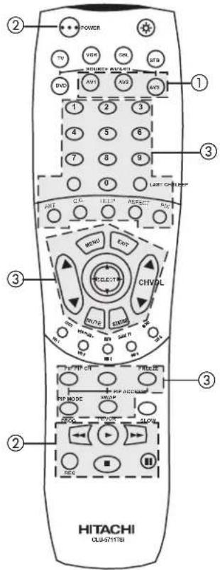
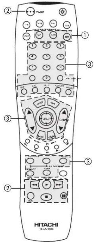
To operate additional audio/video equipment, point the remote at the remote sensor of the component you wish to control and press the AV1, AV2 or AV3 button. This button will blink, indicating that the remote will now control the desired component. (See page 34 for instructions on how to program the remote to control additional Audio/Video equipment.)
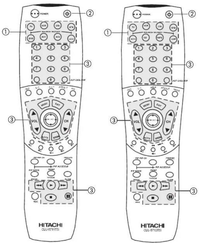
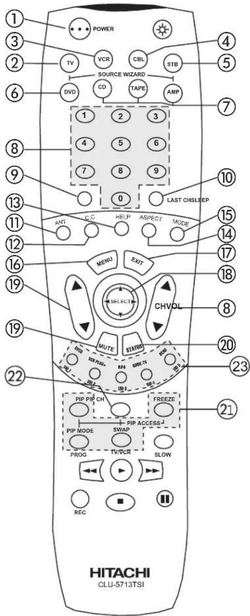
① These buttons allow the remote to control your TV, VCR, cable box, satellite receiver, DVD player, or other Audio/Video equipment depending on which mode is chosen, as explained above.
②,③ LIGHT BUTTON
When you are in a dark room, press the light button ② on the remote to light up the buttons shown in ③ and the source button will blink. The light will stay on for about 8 seconds if the light button is not pressed again. These buttons will not appear to light if the room is too bright.
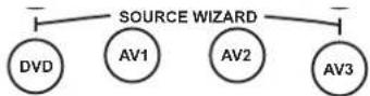
NOTE: 1. Your remote control "SOURCE WIZARD" buttons are either labeled as "AV1, AV2 and AV3," or "CD, TAPE, and AMP." If your remote control "SOURCE WIZARD" buttons are labeled as "AV1, AV2, and AV3," please program your Audio/Video components as follow for best performance. Use "AV1" to program your CD brand. Use "AV2" to program your TAPE brand, and use "AV3" to program your AMPLIFIER/RECEIVER brand.
AV1-Use for CD brand AV2-Use for TAPE brand AV3-Use for AMPLIFIER/RECEIVER brand.
- Your remote control button to directly access the THEATER MODE is either labeled as "PIX" or "MODE".
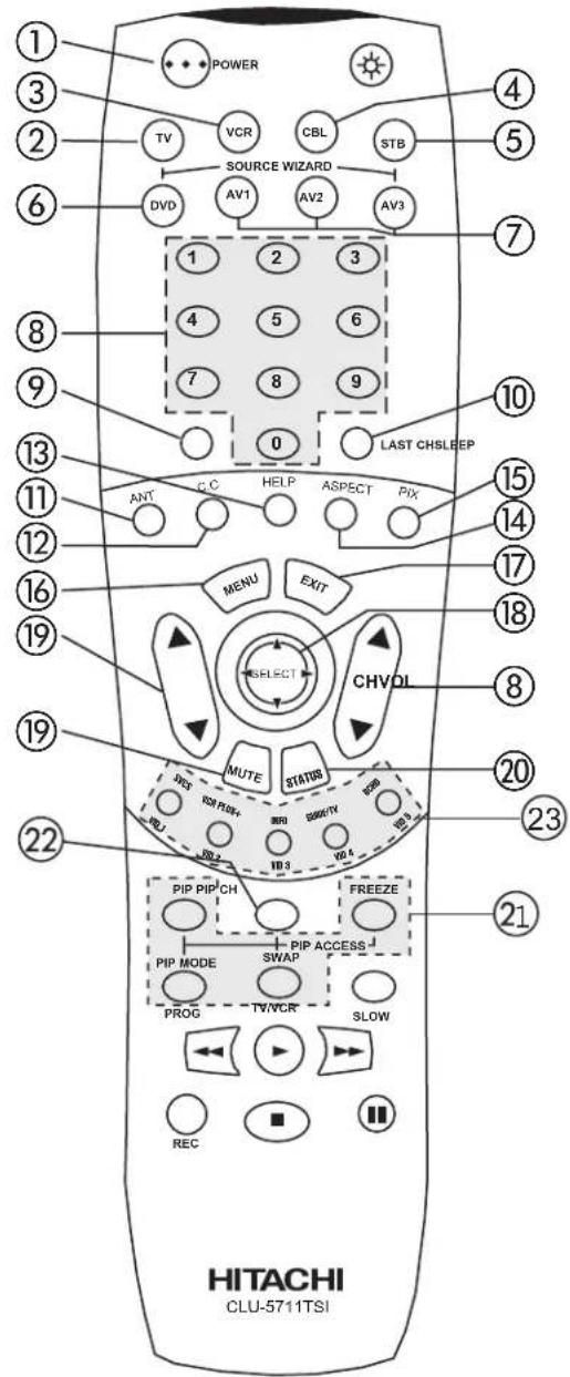
① POWER button
Press this button to turn the TV set on or off when the remote is in TV mode. (See page 23 for instructions on how to set the remote control to TV mode.)
② TV button
When the TV button is pressed, it will blink, to indicate the remote is in TV mode.
③ VCR button
When the VCR button is pressed, it will blink to indicate the remote is in VCR mode. (see page 30)
④ CABLE (CBL)
When the CABLE button is pressed, it will blink to indicate the remote is in CABLE mode. (see page 31)
⑤ SET-TOP-BOX (STB)
When the STB button is pressed, it will blink to indicate the remote is in STB mode. (see page 32) If you have a Satellite receiver, use this button to program your Satellite receiver. (see page 32)
⑥ DVD button
When the DVD button is pressed, it will blink to indicate the remote is in DVD mode. (see page 33)
HOW TO USE THE GENIUS REMOTE TO CONTROL YOUR TV
⑦ AV1, AV2, AV3, or CD, TAPE, AMP buttons
When pressed, each of these buttons will blink to indicate the remote is in Audio/Video mode. (see page 34)
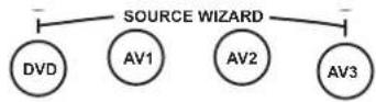
NOTE: Your remote control "SOURCE WIZARD" buttons are either labeled as "AV1, AV2 and AV3," or "CD, TAPE, and AMP." If your remote control "SOURCE WIZARD" buttons are labeled as "AV1, AV2, and AV3," please program your Audio/Video components as follow for best performance. Use "AV1" to program your CD brand. Use "AV2" to program your TAPE brand, and use "AV3" to program your AMPLIFIER/RECEIVER brand.
AV1-Use for CD brand
AV2-Use for TAPE brand
AV3-Use for AMPLIFIER/RECEIVER brand.
⑧ CHANNEL selector buttons
CHANNEL selector buttons are used to set FAVORITE CHANNELS, CHANNEL MEMORY, etc.
Enter one, two, or three numbers to select channels. Enter "0" first for channels 1 to 9, or simply press the single digit channel you wish to tune then wait a few seconds for the TV to tune. For channels 100 and above, press the "1" button, wait until two dashes appear next to the channel display on your TV, then enter the remaining two numbers using the number buttons.
Channel selection may also be performed by pressing CH up (▲) or down (▼).
NOTE: The TV may not receive some channels if you are not in the correct ANTENNA/CABLE mode. (see page 40)
⑨ SLEEP button
Press this button to display the sleep timer in the lower left corner of the screen. Every subsequent press of this button will add 15 minutes to this timer, up to a maximum of three hours. Once set, use STATUS when you want to view time remaining. If the SLEEP button is pressed while the timer is set, it will reset to the original condition.
Use this button to select between the last two channels viewed. (Good for watching two sporting events, etc.)
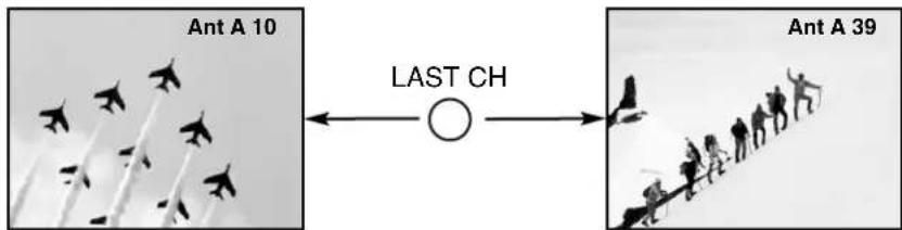
flowchart
graph LR
    A["Ant A 10"] --> B["○"]
    B --> C["Last CH"]
    C --> D["Ant A 39"]
⑪ ANTENNA button
The ANT button will select between Antenna A and Antenna B each time the button is pressed.
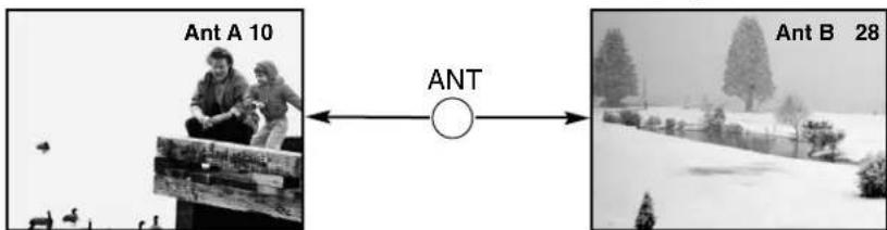
⑫ C.C. button
Press this button to quickly turn the Closed Caption feature on, off and auto (see page 55 for more information).
⑬ HELP button
Press this button when a menu is displayed to view HELP text, which gives a description of the displayed menu. The HELP text will be displayed every time a MENU is displayed, until this button is pressed again.
⑭ ASPECT button
Press this button to quickly change the PICTURE FORMATS aspect ratio. (See page 46-47 for more information)
⑮ PIX or MODE button
Press this button repeatedly to direct access THEATER MODE between Sport, News, Movie, and Music.
⑯ MENU button
The MENU button will start the On-Screen Display.
⑰ EXIT button
When in MENU mode, this button will exit all On-Screen Displays.
⑱ THUMB STICK/SELECT button
All the On-Screen Display features can be set or adjusted by using the THUMB STICK.
The THUMB STICK will highlight functions or adjust and set different features. Press the THUMB STICK toward desired direction and press down to SELECT.
⑲ VOLUME, MUTE button
Press the VOLUME up (▲) or down (▼) button until you obtain the desired sound level.
To reduce the sound to one half of normal volume (SOFT MUTE) to answer the telephone, etc., press the MUTE button. Press the MUTE button again to turn the sound off completely (MUTE). To restore the sound, press the MUTE button one more time, or press the VOLUME Up (▲) button.

flowchart
graph LR
    A["Volume 8"] --> B["MUTE"]
    B --> C["Soft Mute 8"]
    C --> D["MUTE"]
    D --> E["Mute 8"]
Closed Captioning will display when MUTE/SOFT MUTE is on and Closed Caption is set to AUTO (See page 55).
⑳ STATUS button
Press this button when no menu is displayed when you want to check the channel being received, the picture source, if the channel has stereo (ST) or second audio program (SAP), the time, CHANNEL ID and if the SLEEP timer is set.
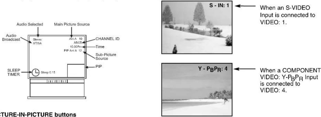
②1 PICTURE-IN-PICTURE buttons
See separate section on pages 27\~29 for a description.
② PIP CH button
Use the PIP CH button to select between main picture and sub-picture tuning. The channel number which is highlighted indicates what channel is being controlled.
②3 VID1 \~ VID5
When the remote control is in TV mode, press these buttons to directly select the video input sources between the five video inputs. When the remote control is in Set-Top-Box mode (STB) these buttons will control the Set-Top-Box or satellite receiver.
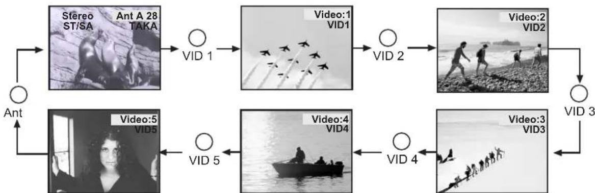
flowchart
graph TD
    A["Ant"] --> B["Stereo ST/SA"]
    B --> C["Ant A 28 TAKA"]
    C --> D["VID 1"]
    D --> E["Video:1 VID1"]
    E --> F["VID 2"]
    F --> G["Video:2 VID2"]
    G --> H["VID 3"]
    H --> I["Video:3 VID3"]
    I --> J["VID 4"]
    J --> K["Video:4 VID4"]
    K --> L["Video:5 VID5"]
    L --> M["Ant"]
    M --> N["Ant"]
Your HITACHI Projection TV incorporates Dual Tuner technology designed for improved viewing enjoyment. This Dual Tuner feature allows you to view antenna inputs on both the main picture and sub-picture simultaneously, with separate tuning control for each. The Dual Tuner can operate with only one input (ANT A only) or two inputs (ANT A and ANT B).
ANT A input can be viewed as both the main picture and the sub-picture simultaneously. ANT B can only be viewed as a main picture. To select between main picture and PIP sub-picture tuning, press the PIP CH button on the remote. The highlighted channel display will move with every press of the PIP CH button. When the top channel display is highlighted, channel tuning is for the main picture. When the lower channel display is highlighted, channel tuning is for the PIP sub-picture.
The Picture-in-Picture feature is convenient when you want to watch more than one program at the same time. You can watch a TV program while viewing other programs from the ANT A source or any of the video inputs.
Models: 61UWX10BA, 53UWX10BA, 43UWX10B
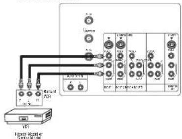
Use above connection to view VCR program as a sub-picture while viewing another program as main picture (ANT A, ANT B, V:2, V:3, V:4, or V:5). You may also view the VCR program as a main picture while viewing another program as a sub-picture (ANT A, V:2, V:3, V:4, or V:5).
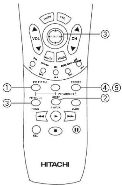
① PIP button
Press the PIP button and a sub-picture will appear in one of the three different modes (SINGLE, SPLIT or SURF), depending on the last selection of the PIP mode. To change the PIP mode, use the PIP MODE button to cycle through the three different modes.
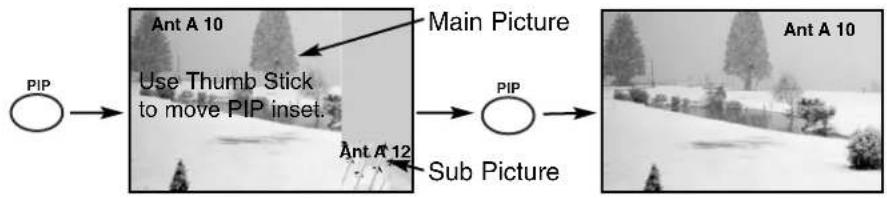
SINGLE MODE PIP
Press the PIP button and a sub-picture appears in one of the three different modes (SINGLE, SPLIT or SURF), depending on the last selection of the PIP mode. Press the PIP button again to remove the sub-picture from the screen. Use the PIP CH button to select between main and sub-picture tuning control (indicated by gray highlighted channel display.) Press the VID1, VID2, VID3, VID4 or VID5 button when sub-picture channel tuning is being controlled, to change between VIDEO: 1, VIDEO: 2, VIDEO: 3, VIDEO:4 and VIDEO:5 and ANT:A source. (ANT B source cannot be viewed as a sub-picture.)
flowchart
graph LR
    A["PIP"] --> B["Use Thumb Stick to move PIP inset"]
    B --> C["Main Picture"]
    C --> D["Sub Picture"]
    D --> E["Ant A 10"]
    D --> F["Ant A 12"]
NOTES: 1. When using Y-P B^PB input, only 480i signal can be viewed as a single mode PIP.
- When ANT B is selected as the main channel, the SWAP feature is disabled.
- Only sound from the main picture can be heard.
- In SINGLE PIP mode, thumb stick CURSOR ▲, ▼ will move the sub picutre up/down.
PICTURE-IN-PICTURE CONT.
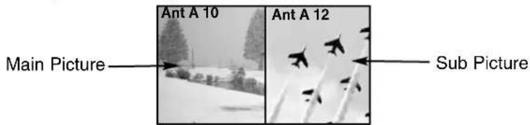
SPLIT MODE PIP
Split Mode PIP displays the main picture and sub-picture evenly on the screen.
SURF MODE PIP
This feature will automatically scan all active channel numbers (those set in memory) and display them as PIP sub-pictures, along the right edge of the screen. Press the PIP button a second time to remove the sub-pictures from the screen.

flowchart
graph LR
    A["Ant A 28"] --> B["PIP"]
    B --> C["Image 09: Vertical sequence of points"]
    C --> D["Image 12: Vertical sequence of points"]
    D --> E["PIP"]
NOTES: 1. If no buttons are pressed when in SURF mode, auto-scanning will continuously scan channels in memory. (see page 41)
2. If a channel is tuned during this SURF scanning, sub-pictures will be removed from the screen.
3. SURF MODE PIP is allowed only when ANT A is selected as the main channel.
4. If PARENTAL CONTROL MOVIE/TV RATINGS setting is ON, PIP SURF mode will be deactivated.
5. Closed Caption will not appear when PIP SURF mode is on.
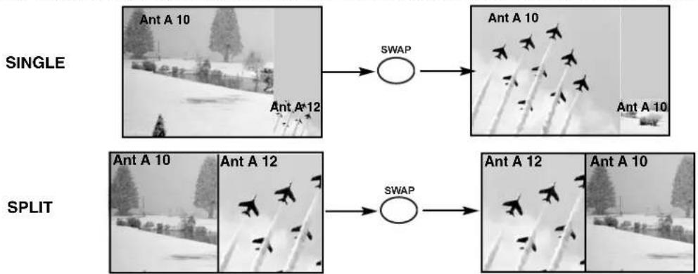
② SWAP button
If you wish to switch what is being shown on the main picture to the sub-picture, press the SWAP button.
flowchart
graph LR
    A["SINGLE"] --> B["SWAP"]
    B --> C["Ant A 10"]
    C --> D["Ant A 12"]
    D --> E["SWAP"]
    E --> F["Ant A 10"]
    F --> G["Ant A 12"]
    G --> H["SWAP"]
NOTES: 1. The SWAP button will only operate in SINGLE/SPLIT PIP mode.
2. The SWAP function will not operate if ANT B input is set as the main channel (ANT B input cannot be displayed as a sub-picture.)
③ PIP MODE button
To change between the three different PIP modes (SINGLE, SPLIT or SURF) press the PIP MODE button when PIP is ON. Each press of this button will change PIP to a different mode. Pressing this button three times will cycle through both PIP modes.

flowchart
graph LR
    A["Ant A 10"] --> B["Ant A 12"]
    B --> C["PIP MODE"]
    C --> D["Ant A 10"]
    D --> E["Ant A 12"]
    E --> F["PIP MODE"]
    F --> G["2"]
    G --> H["3"]
    H --> I["4"]
    I --> J["PIP MODE"]
NOTE: When using Y-P _B^P R input, only 480i signal can be viewed as a single mode PIP.
④ FREEZE button (With PIP ON)
If you wish to freeze the sub-picture, press the FREEZE button. This is convenient when trying to write down the address for a mail order company, recording statistics for a sporting event, etc. To return the picture to motion, press the FREEZE button again.
NOTE: When PIP is on, the FREEZE function will only operate when SINGLE/SPLIT PIP mode is chosen.
⑤ FREEZE button (With PIP OFF)
Press the FREEZE button to freeze the picture, depending on the PIP mode selected (SINGLE, SPLIT or STROBE). To change FREEZE modes, use the PIP MODE button to cycle through the three different modes.
SINGLE FREEZE
PIP should be in SINGLE mode. Press the FREEZE button to freeze one frame of the picture you are currently viewing. Press this button again or PIP to return to normal viewing.

flowchart
graph LR
    A["Hot Springs Clay Mask\nC/O John Doe\nRun-Spa Retreat\nP.O. Box 55512\nAny Town, USA 98765\nCheck or\nMoney Order Only\n1-800-555-1212"] --> B["FREEZE"]
    B --> C["Ant A 10"]
    C --> D["FREEZE"]
SPLIT FREEZE(with PIP off)
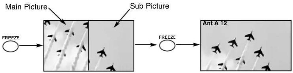
PIP should be in SPLIT mode. Press the FREEZE button to freeze the picture you are currently viewing (only the left sub-picutre will freeze). Press this button again or PIP to return to normal viewing.
flowchart
graph LR
    A["Main Picture"] --> B["Sub Picture"]
    B --> C["Ant A 12"]
    D["FREEZE"] --> E["Processing Unit"]
    E --> F["FREEZE"]
STROBE FREEZE(with PIP OFF)
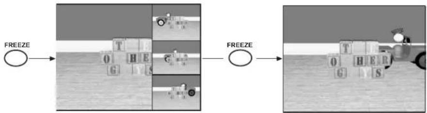
PIP should be in SURF mode. Press the FREEZE button to freeze three frames of the picture you are currently viewing. Press this button again or PIP to return to normal viewing. This feature is useful for viewing a moving picture that has many details, for
flowchart
graph LR
    A["FREEZE"] --> B["Game Block 1"]
    B --> C["Game Block 2"]
    C --> D["Game Block 3"]
    D --> E["Game Block 4"]
    E --> F["Game Block 5"]
    F --> G["Game Block 6"]
    G --> H["Game Block 7"]
    H --> I["Game Block 8"]
    I --> J["Game Block 9"]
    J --> K["Game Block 10"]
    K --> L["Game Block 11"]
    L --> M["Game Block 12"]
    M --> N["Game Block 13"]
    N --> O["Game Block 14"]
    O --> P["Game Block 15"]
    P --> Q["Game Block 16"]
    Q --> R["Game Block 17"]
    R --> S["Game Block 18"]
    S --> T["Game Block 19"]
    T --> U["Game Block 20"]
CAUTION: A pattern burn may develop if the sub-picture is left in the same corner permanently. If the PIP feature is used frequently, occasionally MOVE the sub-picture using the THUMB STICK ◀, ▶, ▲, or ▼.
NOTES: Each freeze frame is delayed about 0.1 (1/10) second.
Operating the precoded function for your VCR.
This remote is designed to operate different types of VCRs. You must first program the remote to match the remote system of your VCR. (refer to page 35 for pre-codes)
- Turn ON your VCR.
- Aim the remote control at the front of your VCR.
- Press and release the VCR button to switch to VCR pre-coded mode.
- Hold down the VCR button on the remote and enter the two digit preset code that matches your VCR, as shown on page 35. The indicator light will flash 3 times if the code was accepted.
- Aim the remote at the VCR and press the POWER button. The remote will turn off your VCR when the correct two digit preset code is entered. When this occurs, the remote control is programmed for your VCR. If the VCR does not turn off, try a different two digit preset code.
- The remote will now control your VCR.
NOTES:
- If your VCR cannot be operated after performing the above procedures, your VCR's code has not been precoded into the remote.
- In the unlikely event that your VCR cannot be operated after performing the above procedures, please consult your VCR operating guide.
- The remote control will remember the codes you have programmed until the batteries are removed from the remote control. After replacing the batteries repeat the entire programming procedure as stated above.
- The MENU button will act as the VCR MENU button for HITACHI VCRs.
- The LAST CH button will act as your VCR ENTER button if required.
- The SLEEP button will act as your VCR '100' button if required.
① VCR Button
This button allows the remote to control your VCR by setting it to VCR mode.
② PRECODED VCR Buttons
These buttons transmit the chosen precoded VCR codes. For some VCRs, you must press the RECORD button twice to record a program.
③ EXCLUSIVE TV Buttons
These buttons are for operating the TV.
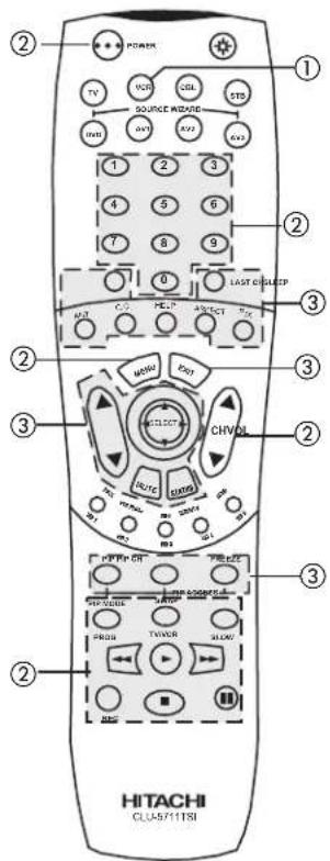
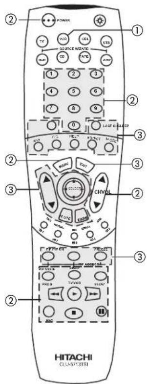
MY VCR CODE IS: ____
NOTE: Refer to instruction manual of the VCR for operation of the buttons exclusively for the VCR.
Operating the precoded function for your cable box.
This remote is designed to operate different types of cable boxes. You must first program the remote to match the remote system of your cable box. (refer to page 35)
-
Turn ON your cable box.
-
Aim the remote control at the front of your cable box.
-
Press and release the Cable (CBL) button to switch to Cable pre-coded mode.
-
Hold down the CBL button on the remote and enter the two digit preset code that matches your cable box as shown on page 35. The indicator light will flash 3 times if the code was accepted.
-
Aim the remote at the cable box and press the POWER button. The remote will turn off your cable box when the correct two digit preset code is entered. When this occurs, the remote control is programmed for your cable box. If the cable box does not turn off, try a different two digit preset code.
-
The remote will now control your Cable box.
NOTES:
-
If your cable box cannot be operated after performing the above procedures, your cable box code has not been precoded into the remote.
-
In the unlikely event that your cable box cannot be operated after performing the above procedures, please consult your cable box operating guide.
-
The remote control will remember the codes you have programmed until the batteries are removed from the remote control. After replacing the batteries repeat the entire programming procedure as stated above.
-
The LAST CH button will act as the cable box ENTER button if required.
-
The SLEEP button will act as your cable box '100' button if required.
-
The ANT button will act as the TV/STB button when in STB mode.
① CABLE (CBL) button
This button allows the remote to control your cable box by setting it to CABLE mode.
② PRECODED CABLE BOX buttons
These buttons transmit the chosen precoded cable codes.
③ EXCLUSIVE TV buttons
These buttons are for operating the TV.
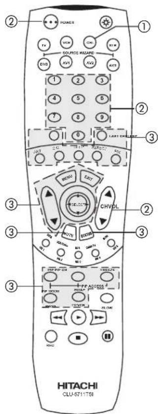
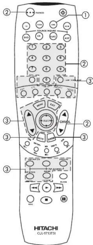
MY CABLE BOX CODE IS:____
NOTE: Refer to instruction manual of the Cable Box for operation of the buttons exclusively for the Cable Box.
Operating the precoded function for your set-top-box/satellite receiver.
This remote is designed to operate different types of set-top-box/satellite systems. You must first program the remote to match the remote system of your set-top-box/satellite systems. (refer to page 35)
-
Turn ON your set-top-box/satellite systems.
-
Aim the remote control at the front of your set-top-box/satellite systems.
-
Press and release the SET-TOP-BOX (STB) button to switch to set-top-box/satellite pre-coded mode.
-
Hold down the STB button on the remote and enter the two digit preset code that matches your set-top-box/satellite receiver as shown on page 35. The indicator light will flash 3 times if the code was accepted.
-
Aim the remote at the set-top-box/satellite receiver and press the POWER button. The remote will turn off your set-top-box/satellite receiver when the correct two digit preset code is entered. When this occurs, the remote control is programmed for your set-top-box/satellite receiver. If the set-top-box/satellite receiver does not turn off, try a different two digit preset code.
-
The remote will now control your set-top-box/satellite receiver.
NOTES:
-
If your set-top-box/satellite receiver cannot be operated after performing the above procedures, your set-top-box/satellite receiver code has not been precoded into the remote.
-
In the unlikely event that your set-top-box/satellite receiver cannot be operated after performing the above procedures, please consult your set-top-box/satellite receiver operating guide.
-
The remote control will remember the codes you have programmed until the batteries are removed from the remote control. After replacing the batteries repeat the entire programming procedure as stated above.
-
The ANT button will act as the TV/STB button when in STB mode.
① SET-TOP-BOX (STB) button
This button allows the remote to control your satellite receiver by setting it to SET-TOP-BOX/SATELLITE mode.
② PRECODED SET-TOP-BOX/SATELLITE RECEIVER buttons
These buttons transmit the chosen precoded set-top-box/satellite codes.
③ EXCLUSIVE TV buttons
These buttons are for operating the TV.
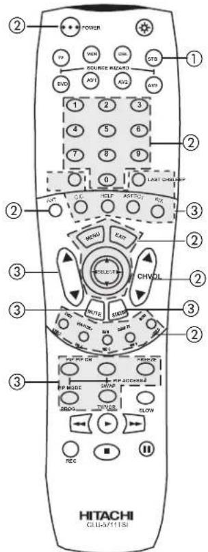
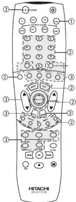
MY SATELLITE RECEIVER/STB CODE IS:____
NOTE: Refer to instruction manual of the set-top-box/satellite receiver for operation of the buttons exclusively for the set-top-box/satellite receiver.
Operating the precoded function for your DVD player.
This remote is designed to operate different types of DVD players. You must first program the remote to match the remote system of your DVD player. (refer to page 35 for pre-codes)
- Turn ON your DVD player.
- Aim the remote control at the front of your DVD player.
- Press and release the DVD button to switch to DVD pre-coded mode.
- Hold down the DVD button on the remote and enter the two digit preset code that matches your DVD player, as shown on page 35. The indicator light will flash 3 times if the code was accepted.
- Aim the remote at the DVD player and press the POWER button. The remote will turn off your DVD player when the correct two digit preset code is entered. When this occurs, the remote control is programmed for your DVD player. If the DVD player does not turn off, try a different two digit preset code.
- The remote will now control your DVD player.
NOTES:
- If your DVD player cannot be operated after performing the above procedures, your DVD player's code has not been precoded into the remote.
- In the unlikely event that your DVD player cannot be operated after performing the above procedures, please consult your DVD player operating guide.
- The remote control will remember the codes you have programmed until the batteries are removed from the remote control. After replacing the batteries repeat the entire programming procedure as stated above.
① DVD Button
This button allows the remote to control your DVD player by setting it to DVD mode.
② PRECODED DVD Buttons
These buttons transmit the chosen precoded DVD codes.
③ EXCLUSIVE TV Buttons
These buttons are for operating the TV.
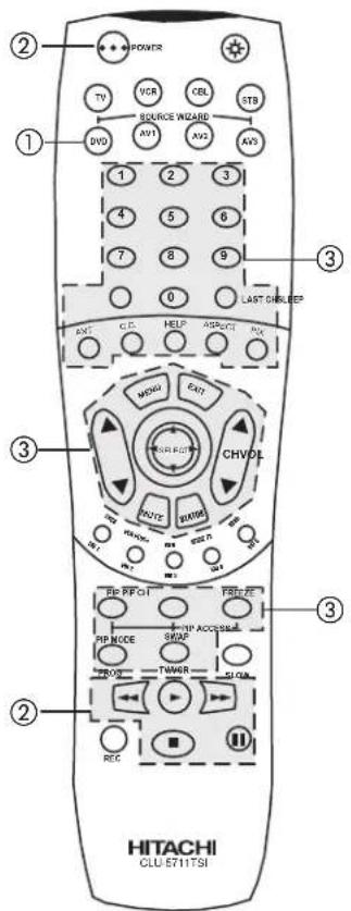
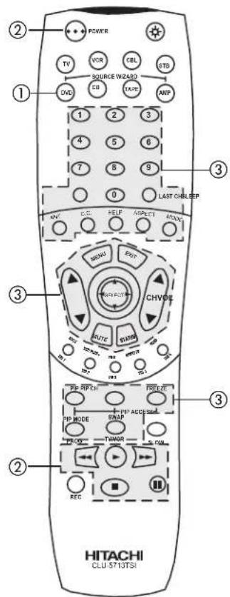
NOTE: Refer to instruction manual of the DVD player for operation of the buttons exclusively for the DVD player.
Operating the precoded function for your Audio/Video component.
This remote is designed to operate different types of Audio/Video component. You must first program the remote to match the remote system of your Audio/Video component. (refer to page 35 for pre-codes)
-
Turn ON your Audio/Video component you wish to control with the Remote.
-
Aim the remote control at the front of your Audio/Video component.
-
Press and release the AV1, AV2 or AV3 button to switch to Audio/Video component pre-coded mode.
-
Hold down the AV1, AV2 or AV3 button on the remote and enter the two digit preset code that matches your Audio/Video component, as shown on page 35. The indicator light will flash 3 times if the code was accepted.
-
Aim the remote at the Audio/Video component and press the POWER button. The remote will turn off your Audio/Video component when the correct two digit preset code is entered. When this occurs, the remote control is programmed for your Audio/Video component. If the Audio/Video component does not turn off, try a different two digit preset code.
-
The remote will now control your Audio/Video component.
-
Repeat steps 1 - 6 if you wish to program the remote to control another Audio/Video component. Be sure to use a different A/V button on the remote, since only one component can be programmed per button.
NOTES:
-
Your remote control "SOURCE WIZARD" buttons are either labeled as "AV1, AV2 and AV3," or "CD, TAPE, and AMP." If your remote control "SOURCE WIZARD" buttons are labeled as "AV1, AV2, and AV3," please program your Audio/Video components as follow for best performance. Use "AV1" to program your CD brand. Use "AV2" to program your TAPE brand, and use "AV3" to program your AMPLIFIER/RECEIVER brand.
-
If your Audio/Video component cannot be operated after performing the above procedures, your Audio/Video component's code has not been precoded into the remote.
-
In the unlikely event that your Audio/Video component cannot be operated after performing the above procedures, please consult your Audio/Video equipment operating guide.
-
The remote control will remember the codes you have programmed until the batteries are removed from the remote control. After replacing the batteries repeat the entire programming procedure as stated above.
① AV1, AV2, AV3 Buttons
These buttons allows the remote to control your Audio/Video equipment by setting it to Audio/Video mode.
② PRECODED AUDIO/VIDEO Buttons
These buttons transmit the chosen precoded Audio/Video component codes.
③ EXCLUSIVE TV Buttons
These buttons are for operating the TV.
MY AUDIO/VIDEO EQUIPMENT CODE IS:
AV1 (CD)
AV2 (TAPE)
AV3 (AMP/RCVR)
NOTE: Refer to instruction manual of the Audio/Video equipment for operation of the buttons exclusively for the Audio/Video equipment.
| VCR BRAND. | CODE |
| Adventura | 01 |
| Aiko | 09 |
| Aiwa | 01 |
| Akai | 02, 47, 48 |
| American High | 23 |
| Asha | 44 |
| Audiovox | 24 |
| Beaumark | 44 |
| Bell & Howell | 32 |
| Broksonic | 33, 34, 41 |
| Calix | 24 |
| Canon | 23 |
| Carver | 31 |
| CCE | 09, 30 |
| Citizen | 09, 24 |
| Colt | 30 |
| Craig | 19, 24, 30, 44 |
| Curtis Mathes | 02, 23, 46 |
| Cybernex | 44 |
| Daewoo | 09, 17 |
| Dynatech | 01 |
| Electrophonic | 24 |
| Emerex | 08 |
| Emerson | 01, 09, 13, 16, 24, 27, 28, 33, 34, 36, 41, 47 |
| Fisher | 19, 21, 32 |
| Fuji | 10, 23 |
| Funai | 01 |
| Garrard | 01 |
| GE | 04, 23, 40, 46 |
| Goldstar | 24, 25, 43 |
| Gradiente | 01 |
| Harley Davidson | 01 |
| Harmon/Kardon | 25 |
| Harwood | 30 |
| Headquarter | 18 |
| Hi-Q | 19 |
| Hitachi | 01, 02, 03, 04, 05 |
| Jensen | 02 |
| JVC | 02, 14, 26 |
| KEC | 09, 24 |
| Kenwood | 02, 25, 26 |
| KLH | 30 |
| Kodak | 23, 24 |
| Lloyd | 01 |
| Lloyd's | 27 |
| Logik | 30 |
| LXI | 24 |
| Magnavox | 15, 23, 31, 35 |
| Magnin | 44 |
| Marantz | 23, 31 |
| Marta | 24 |
| Matsushita | 23 |
| MEI | 23 |
| Memorex | 01, 15, 18, 19, 20, 23, 24, 32, 44 |
| MGA | 16, 47 |
| MGN Technology | 44 |
| Minolta | 03, 05 |
| Mitsubishi | 16, 26, 39, 47, 48 |
| Motorola | 20, 23 |
| MTC | 01, 44 |
| Multitech | 01, 30 |
| NEC | 02, 25, 26, 32 |
| Nikko | 24 |
| Noblex | 44 |
| Olympus | 12, 23 |
| Optimus | 20, 24, 32 |
| Panasonic | 11, 12, 23, 38 |
| Penney | 03, 23, 24, 25, 44 |
| Pentax | 03, 04, 05 |
| Philco | 23 |
| Phillips | 23, 31 |
| Pilot | 24 |
| Pioneer | 26 |
| Protec | 30 |
| Pulsar | 15 |
| Quarter | 18 |
| Quartz | 18 |
| Quasar | 23 |
| Radio Shack | 01, 24 |
| Radix | 24 |
| Randex | 24 |
| RCA | 03, 04, 05, 35, 40, 46 |
| Realistic | 01, 18, 19, 20,21, 23, 24, 32, 44 |
| Ricoh | 22 |
| Runco | 15 |
| Samsung | 17, 44 |
| Sanky | 15, 20 |
| Sansui | 02, 26 |
| Sanyo | 18, 19, 32, 44 |
| Scott | 16, 17, 33, 34, 36, 41 |
| Sears | 03, 05, 18, 19,21, 23, 24, 32 |
| Sharp | 20 |
| Shintom | 30 |
| Shogun | 44 |
| Singer | 30 |
| Sony | 08, 10, 22, 23 |
| STS | 03 |
| Sylvania | 01, 16, 23, 31 |
| Symphonic | 01 |
| Tatung | 02 |
| Teac | 01, 02 |
| Technics | 23, 38 |
| Teknika | 01, 23, 24 |
| TMK | 27, 44 |
| Toshiba | 16, 17, 21, 36 |
| Totvision | 24, 44 |
| Unitech | 44 |
| Vector | 17 |
| Vector Research | 25 |
| Video Concepts | 17, 47 |
| Videosonic | 44 |
| Wards | 01, 03, 19, 20, 23,30, 35, 36, 44, 46 |
| XR-1000 | 01, 23, 30 |
| Yamaha | 25 |
| Zenith | 10, 15, 22 |
| DVD BRAND. | CODE |
| Denon | 04 |
| Hitachi | 07, 12 |
| JVC | 01 |
| Kenwood | 04 |
| Magnavox | 05 |
| Mitsubishi | 10 |
| Panasonic | 04 |
| Phillips | 06 |
| Pioneer | 03 |
| RCA (Proscan) | 09 |
| Samsung | 12 |
| Sony | 02 |
| Toshiba | 05 |
| Yamaha | 08 |
| Zenith | 05, 11 |
| CABLE BRAND | CODE |
| ABC | 01, 07, 08, 17, |
| 18, 20, 36, 37, 49 | |
| Antronix | 39 |
| Archer | 11, 24, 39 |
| Belcor | 32 |
| Cable Star | 32 |
| Century | 11 |
| Citizen | 11 |
| Colour Voice | 30, 42 |
| Comtronics | 25, 28 |
| Contec | 21 |
| Dae Ryung | 20 |
| Eastern | 14 |
| Electricord | 31 |
| Everquest | 51 |
| Focus | 52 |
| Garrard | 11 |
| GC Electronics | 32, 39 |
| Gemini | 05, 38, 43, 51 |
| General Instrument | 01, 12 |
| Goldstar | 10, 25 |
| Hamlin | 04, 13, 22, 23 |
| Hitachi | 01 |
| Hytex | 36 |
| Jasco | 11 |
| Jerrold | 01, 08, 12, 37, 49, 50, 51 |
| Macom | 35 |
| Magnavox | 15 |
| Memorex | 03 |
| Movie Time | 29, 31, 33 |
| NSC | 29, 33, 38 |
| Oak | 21, 36, 46 |
| Panasonic | 02, 03, 09 |
| Paragon | 03 |
| Phillips | 11, 15, 16, 26, 30, 42, 43, 44 |
| Pioneer | 06, 10, 19 |
| Popular Mechanics | 52 |
| Pulsar | 03 |
| RCA | 02 |
| Realistic | 39 |
| Recoton | 52 |
| Regal | 04, 22, 34 |
| Regency | 14 |
| Rembrandt | 01, 38 |
| Runco | 03 |
| Samsung | 10, 25 |
| Scientific Atlanta | 17, 20, 41, 45 |
| Signal | 25, 51 |
| Signature | 01 |
| SL Marx | 25 |
| Sprucer | 02 |
| Starcom | 37, 49, 51 |
| Stargate | 25, 51 |
| Starquest | 51 |
| Starsight | 53, 54 |
| Sylvania | 18 |
| Teleview | 25 |
| Texscan | 18 |
| Tocom | 07, 27, 50 |
| Toshiba | 03 |
| Tusa | 51 |
| TV 86 | 29 |
| Unika | 11, 39 |
| United Artists | 36 |
| United Cable | 49 |
| Universal | 11, 24, 31, 32, 34, 39 |
| Videoway | 47 |
| Viewstar | 15, 28, 29, 40 |
| Zenith | 03, 48 |
| Zentek | 52 |
| SATELLITE BRAND | CODE |
| Echostar | 04 |
| Hitachi | 01 |
| Hughes | 05 |
| RCA | 02 |
| Sony | 03 |
| SET-TOP-BOX | CODE |
| Panasonic | 06 |
| RCA | 07 |
| Samsung | 08 |
| AMPLIFIER BRAND | CODE |
| Aiwa | 05, 06 |
| Carver | 01, 06, 08 |
| Denon | 10 |
| Fisher | 08, 11 |
| Hitachi | 12 |
| JVC | 13 |
| Kenwood | 14, 15, 17, 18 |
| Magnavox | 01, 06 |
| Marantz | 01, 06, 16 |
| MCS | 16 |
| Optimus | 03, 04, 11, 15, 20 |
| Panasonic | 16 |
| Philips | 01, 06 |
| Pioneer | 03, 04, 20, 21, 22 |
| Quasar | 16 |
| Sansui | 06 |
| Sanyo | 11 |
| Sharp | 15 |
| Sony | 05 |
| Technics | 02, 16, 23, 24, 25 |
| Victor | 13 |
| Wards | 03, 05, 06, 08, 20, 21 |
| Yamaha | 15, 26 |
| CD BRAND. | CODE |
| Adcom | 01 |
| Aiwa | 02 |
| California Audio Lab | 03 |
| Carver | 02 |
| Denon | 04 |
| DKK | 05 |
| Emerson | 01 |
| Fisher | 06 |
| Genexxa | 07 |
| Hitachi | 01, 07, 08, 09, 10, 11, 12 |
| JVC | 13 |
| Kenwood | 06, 14, 15 |
| Krell | 02 |
| Magnavox | 02 |
| Marantz | 02, 03 |
| MCS | 03 |
| Mission | 03 |
| NSM | 02 |
| Onkyo | 16 |
| Optimus | 05, 07, 17 |
| Panasonic | 03 |
| Philips | 02 |
| Pioneer | 07, 17 |
| Proton | 02 |
| QED | 02 |
| Quasar | 03 |
| RCA | 01, 21 |
| Realistic | 01 |
| Rotel | 02 |
| SAE | 02 |
| Sansui | 02 |
| Scott | 01 |
| Sony | 05, 18 |
| Technics | 03, 19, 20 |
| Victor | 13 |
| TAPE BRAND | CODE |
| Aiwa | 11, 12 |
| Hitachi | 01, 02, 03, 04 |
| JVC | 05 |
| Kenwood | 06 |
| Optimus | 07 |
| Pioneer | 07 |
| Sony | 09, 10, 11, 12 |
| Wards | 07 |
- Press MENU on the remote control to display the different features on your HITACHI Projection TV.
- Press the THUMB STICK to highlight a different feature.
- Press EXIT on the remote control to quickly exit from a menu.
- Press HELP on the remote control when a menu is displayed, and text will appear giving a description of that menu.

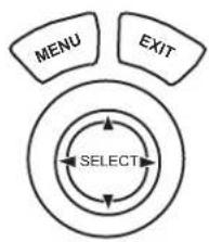
flowchart
graph TD
    A["MENU"] --> B["SELECT"]
    C["EXIT"] --> B
    B --> D["Next Step"]
    style A fill:#f9f,stroke:#333
    style C fill:#f9f,stroke:#333
    style B fill:#ccf,stroke:#333
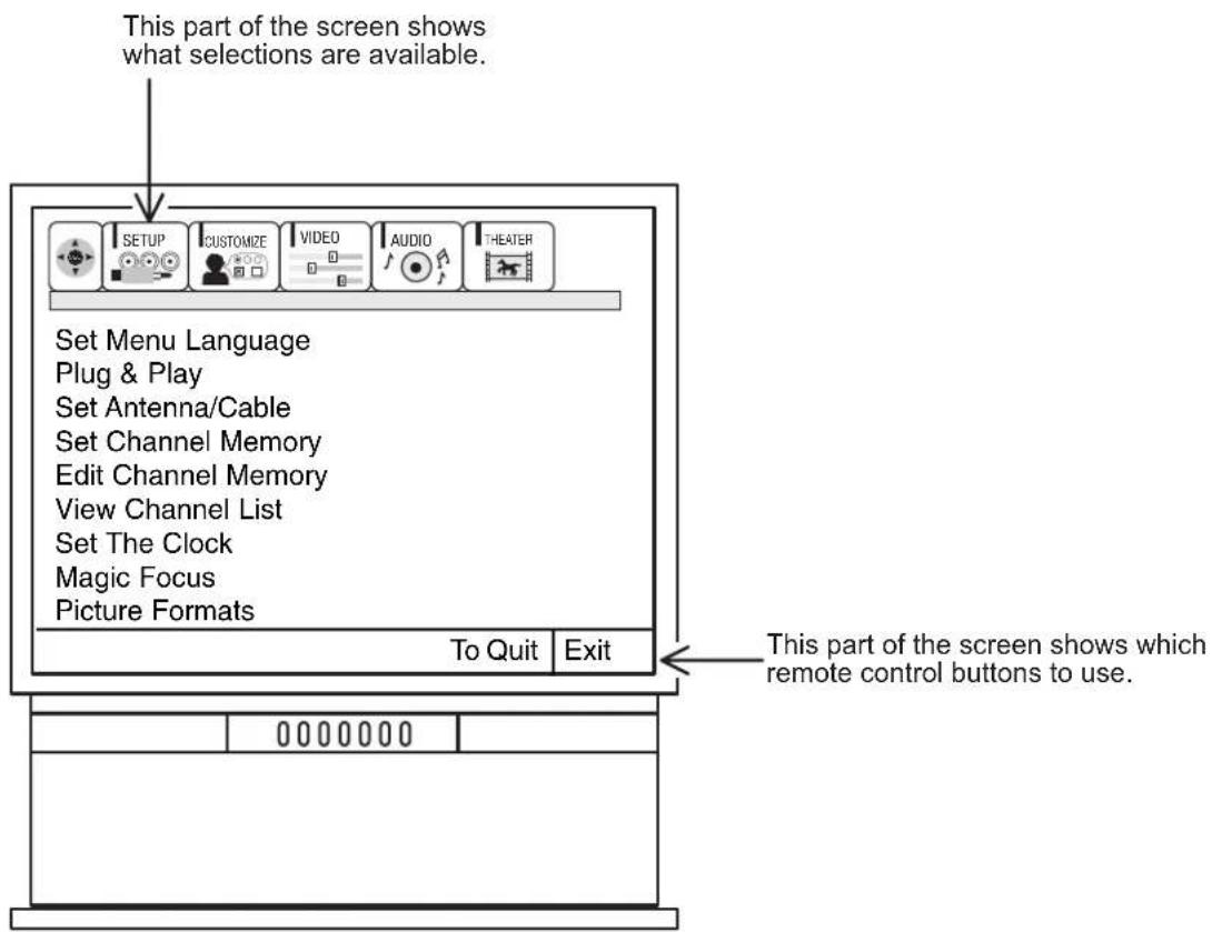
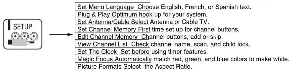
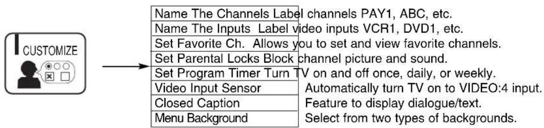
flowchart
graph LR
    A["CUSTOMIZE"] --> B["Name The Channels Label channels PAY1, ABC, etc."]
    A --> C["Name The Inputs Label video inputs VCR1, DVD1, etc."]
    A --> D["Set Favorite Ch. Allows you to set and view favorite channels."]
    A --> E["Set Parental Locks Block channel picture and sound."]
    A --> F["Set Program Timer Turn TV on and off once, daily, or weekly."]
    A --> G["Video Input Sensor"]
    A --> H["Closed Caption"]
    A --> I["Menu Background"]
    B --> J["Automatically turn TV on to VIDEO:4 input. Feature to display dialogue/text. Select from two types of backgrounds."]
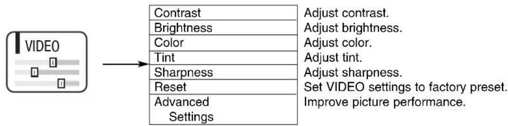
flowchart
graph LR
    A["VIDEO"] --> B["Contrast"]
    A --> C["Brightness"]
    A --> D["Color"]
    A --> E["Tint"]
    A --> F["Sharpness"]
    A --> G["Reset"]
    A --> H["Advanced Settings"]
    B --> I["Adjust contrast."]
    B --> J["Adjust brightness."]
    B --> K["Adjust color."]
    B --> L["Adjust tint."]
    B --> M["Adjust sharpness."]
    B --> N["Set VIDEO settings to factory preset."]
    B --> O["Improve picture performance."]

flowchart
graph LR
    A["AUDIO"] --> B["Equalizer (SWX models)"]
    A --> C["Bass (UWX models)"]
    A --> D["Treble (UWX models)"]
    A --> E["Balance (UWX models)"]
    A --> F["Reset"]
    A --> G["Advanced Settings Improve Sound Performance."]
    B --> H["Precise audio control."]
    C --> I["Adjust bass."]
    D --> J["Adjust treble."]
    E --> K["Adjust balance."]
    F --> L["Set Audio Settings to Factory Preset."]
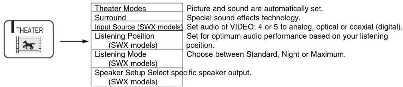
flowchart
graph LR
    A["THEATER"] --> B["Theater Modes"]
    A --> C["Surround"]
    A --> D["Input Source (SWX models)"]
    A --> E["Listening Position (SWX models)"]
    A --> F["Listening Mode (SWX models)"]
    A --> G["Speaker Setup Select spec (SWX models)"]
    B --> H["Picture and sound are automatically set."]
    B --> I["Special sound effects technology."]
    B --> J["Set audio of VIDEO: 4 or 5 to analog, optical or coaxial (digital)."]
    B --> K["Set for optimum audio performance based on your listening position."]
    B --> L["Choose between Standard, Night or Maximum."]
Select SETUP when setting your TV up for the first time. Use the THUMB STICK ▲ or ▼ on the remote to highlight the function desired.
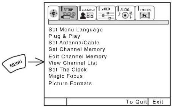
Use THUMB STICK ▲ or ▼ to select the sub-menu of your choice.
NOTE: To see an auto-demonstration of the on-screen displays with HELP text displayed, press and hold the POWER button on the TV set for approximately five seconds. Press the POWER button on the TV again to end the auto-demonstration.
SET MENU LANGUAGE
This feature will allow you to select any one of three different languages for all on-screen displays.
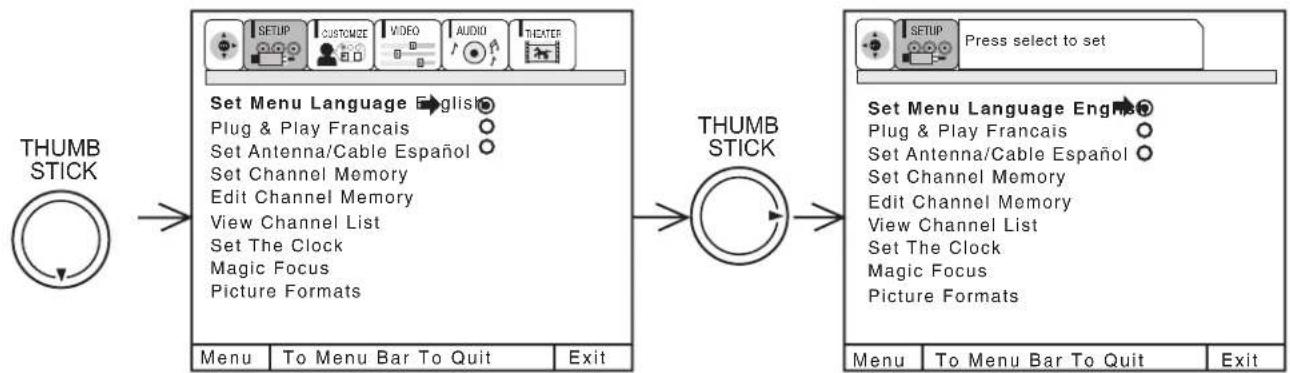
flowchart
graph LR
    A["THUMB STICK"] --> B["Set Menu Language English"]
    B --> C["Plug & Play Francais"]
    B --> D["Set Antenna/Cable Español"]
    B --> E["Set Channel Memory"]
    B --> F["Edit Channel Memory"]
    B --> G["View Channel List"]
    B --> H["Set The Clock"]
    B --> I["Magic Focus"]
    B --> J["Picture Formats"]
    K["THUMB STICK"] --> L["Menu To Menu Bar To Quit Exit"]
    M["Press select to set"] --> N["SETUP Press select to set"]
    O["Set Menu Language Engne"] --> P["Plug & Play Francais"]
    O --> Q["Set Antenna/Cable Español"]
    O --> R["Set Channel Memory"]
    O --> S["Edit Channel Memory"]
    O --> T["View Channel List"]
    O --> U["Set The Clock"]
    O --> V["Magic Focus"]
    O --> W["Picture Formats"]
Use THUMB STICK ▲ or ▼ to highlight SET MENU LANGUAGE of your choice.
Press down on THUMB STICK (SELECT) to select the highlighted language.
Press EXIT to quit menu or THUMB STICK ◀ to return to previous menu.
PLUG & PLAY
This graphic guide function will help you to properly set up your TV or Home Theater System. Simply answer three questions and a graphic will be displayed, showing you the optimum setup for your personalized system.
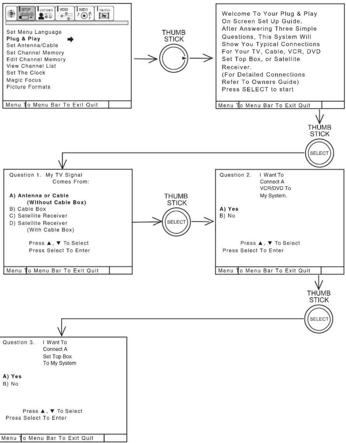
flowchart
graph TD
    A["Set Menu Language\nPlug & Play\nSet Antenna/Cable\nSet Channel Memory\nEdit Channel Memory\nView Channel List\nSet The Clock\nMagic Focus\nPicture Formats"] --> B["Menu To Menu Bar To Exit Quit"]
    B --> C["THUMB STICK"]
    C --> D["Welcome To Your Plug & Play\nOn Screen Set Up Guide.\nAfter Answering Three Simple\nQuestions, This System Will\nShow You Typical Connections\nFor Your TV, Cable, VCR, DVD\nSet Top Box, or Satellite\nReceiver.\n(For Detailed Connections\nRefer To Owners Guide)\nPress SELECT to start"]
    D --> E["THUMB STICK"]
    E --> F["Question 1. My TV Signal\nComes From:\nA) Antenna or Cable\n(Without Cable Box)\nB) Cable Box\nC) Satellite Receiver\nD) Satellite Receiver\n(With Cable Box)\nPress ▲, ▼ To Select\nPress Select To Enter"]
    E --> G["THUMB STICK"]
    G --> H["Question 2. I Want To\nConnect A\nVCR/DVD To\nMy System.\nA) Yes\nB) No\nPress ▲, ▼ To Select\nPress Select To Enter"]
    G --> I["THUMB STICK"]
    I --> J["Question 3. I Want To\nConnect A\nSet Top Box\nTo My System\nA) Yes\nB) No\nPress ▲, ▼ To Select\nPress Select To Enter"]
    I --> K["THUMB STICK"]
    K --> L["Menu To Menu Bar To Exit Quit"]
Press THUMB STICK ▲ or ▼ to highlight the correct answers to all three questions.
Press THUMB STICK ▶ to display the graphic guide.
Press EXIT to quit menu or THUMB STICK ▶ to begin SET CHANNEL MEMORY. (see page 41)
SET ANTENNA/CABLE
Select ANTENNA if you are using an indoor or outdoor antenna. Select CATV if you have cable TV.
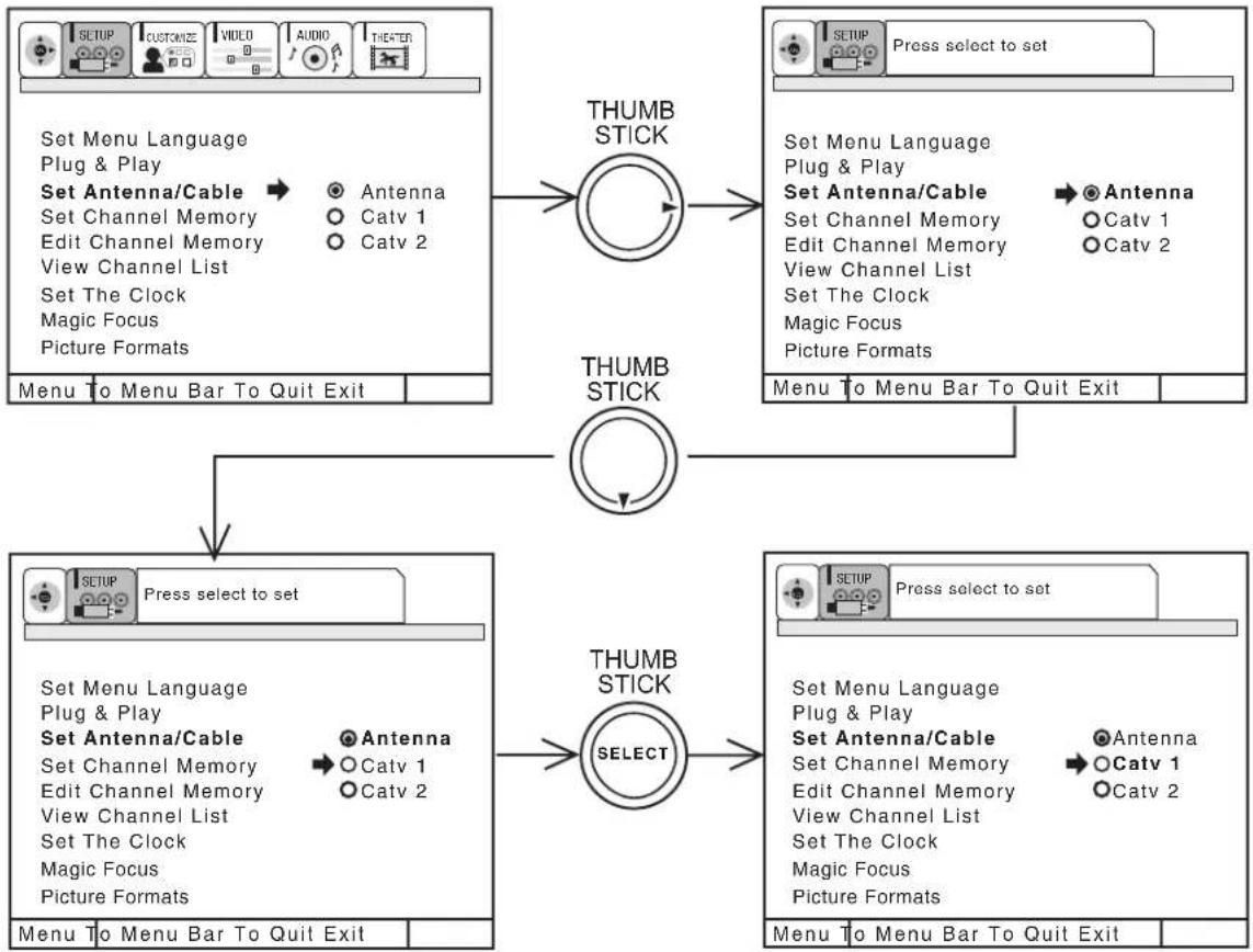
flowchart
graph TD
    A["SETUP"] --> B["Set Antenna/Cable"]
    B --> C["Menu to Menu Bar To Quit Exit"]
    D["SETUP"] --> E["Press select to set"]
    F["SETUP"] --> G["Select"]
    H["SETUP"] --> I["Menu to Menu Bar To Quit Exit"]

    J["THUMB STICK"] --> K["Menu to Menu Bar To Quit Exit"]

    L["THUMB STICK"] --> M["Menu to Menu Bar To Quit Exit"]

    N["THUMB STICK"] --> O["Menu to Menu Bar To Quit Exit"]

    P["THUMB STICK"] --> Q["Menu to Menu Bar To Quit Exit"]

    R["THUMB STICK"] --> S["Menu to Menu Bar To Quit Exit"]

    T["THUMB STICK"] --> U["Menu to Menu Bar To Quit Exit"]

    V["THUMB STICK"] --> W["Menu to Menu Bar To Quit Exit"]

    X["THUMB STICK"] --> Y["Menu to Menu Bar To Quit Exit"]

    Z["THUMB STICK"] --> AA["Menu to Menu Bar To Quit Exit"]

    AB["THUMB STICK"] --> AC["Menu to Menu Bar To Quit Exit"]

    AD["THUMB STICK"] --> AE["Menu to Menu Bar To Quit Exit"]

    AF["THUMB STICK"] --> AG["Menu to Menu Bar To Quit Exit"]

    AH["THUMB STICK"] --> AI["Menu to Menu Bar To Quit Exit"]

    AJ["THUMB STICK"] --> AK["Menu to Menu Bar To Quit Exit"]

    AL["THUMB STICK"] --> AM["Menu to Menu Bar To Quit Exit"]

    AN["THUMB STICK"] --> AO["Menu to Menu Bar To Quit Exit"]

    AP["THUMB STICK"] --> AQ["Menu to Menu Bar To Quit Exit"]

    AR["THUMB STICK"] --> AS["Menu to Menu Bar To Quit Exit"]

    AT["THUMB STICK"] --> AU["Menu to Menu Bar To Quit Exit"]

    AV["THUMB STICK"] --> AW["Menu to Menu Bar To Quit Exit"]

    AX["THUMB STICK"] --> AY["Menu to Menu Bar To Quit Exit"]

    AZ["THUMB STICK"] --> BA["Menu to Menu Bar To Quit Exit"]

    BB["THUMB STICK"] --> BC["Menu to Menu Bar To Quit Exit"]

    BD["THUMB STICK"] --> BE["Menu to Menu Bar To Quit Exit"]

    BF["THUMB STICK"] --> BG["Menu to Menu Bar To Quit Exit"]

    BH["THUMB STICK"] --> BI["Menu to Menu Bar To Quit Exit"]

    BJ["THUMB STICK"] --> BK["Menu to Menu Bar To Quit Exit"]

    BL["THUMB STICK"] --> BM["Menu to Menu Bar To Quit Exit"]

    BN["THUMB STICK"] --> BO["Menu to Menu Bar To Quit Exit"]

    BP["THUMB STICK"] --> BQ["Menu to Menu Bar To Quit Exit"]

    BQ --> BR["THUMB STICK"]
    CA["THUMB STICK"] --> CB["Menu to Menu Bar To Quit Exit"]

    CC["THUMB STICK"] --> CD["Menu to Menu Bar To Quit Exit"]

    CE["THUMB STICK"] --> CF["Menu to Menu Bar To Quit Exit"]

    CG["THUMB STICK"] --> CH["Menu to Menu Bar To Quit Exit"]

    CI["THUMB STICK"] --> CJ["Menu to Menu Bar To Quit Exit"]

    CK["THUMB STICK"] --> CL["Menu to Menu Bar To Quit Exit"]

    CM["THUMB STICK"] --> CN["Menu to Menu Bar To Quit Exit"]

    CO["THUMB STICK"] --> CP["Menu to Menu Bar To Quit Exit"]

    CQ["THUMB STICK"] --> CR["Menu to Menu Bar To Quit Exit"]

    CS["THUMB STICK"] --> CT["Menu to Menu Bar To Quit Exit"]

    CU["THUMB STICK"] --> CV["Menu to Menu Bar To Quit Exit"]

    CW["THUMB STICK"] --> CX["Menu to Menu Bar To Quit Exit"]

    CY["THUMB STICK"] --> CZ["Menu to Menu Bar To Quit Exit"]

    DA["THUMB STICK"] --> DB["Menu to Menu Bar To Quit Exit"]

    DC["THEATER"] --> DD["THEATER"]
    DD --> DP["THEATER"]
Use THUMB STICK ▲ or ▼ to highlight the correct signal mode.
Press down on THUMB STICK to select highlighted signal.
Press EXIT to quit MENU or THUMB STICK ◀ to return to previous menu.
| RECEPTION BAND | ||
| AIR | CATV 1 OR CATV 2 | |
| CATV CHANNEL | Indicated on the screen | |
| VHF 2 ~ 13chUHF 14 ~ 69ch | VHF 2~13 | 2 ~ 13 |
| Mid band A~1A-5 ~ A-1 | 14 ~ 2295 ~ 99 | |
| Super band J~W | 23 ~ 36 | |
| Hyper bandW + 1 ~ W + 28 | 37 ~ 64 | |
| UltrabandW + 29 ~ W + 84 | 65 ~ 125 | |
Reception channels for each mode are shown at the left.
Refer to your cable or TV guide for channel identification standards.
If certain Catv channels are poor or not possible in Catv1 mode, select Catv2.
SET CHANNEL MEMORY
This feature will automatically store active TV channels in SET CHANNEL MEMORY. This will allow you to skip unused channels when using CHANNEL UP (▲) or DOWN (▼).
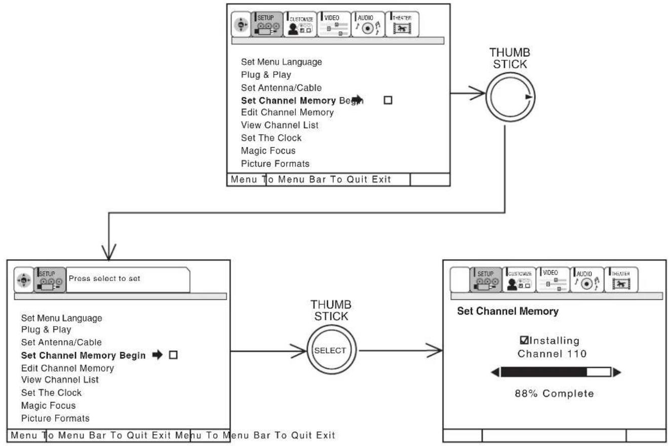
flowchart
graph TD
    A["SETUP"] --> B["CUSTOMIZE"]
    B --> C["VIDEO"]
    C --> D["AUDIO"]
    D --> E["THEATER"]
    F["Set Menu Language"] --> G["Plug & Play"]
    G --> H["Set Antenna/Cable"]
    H --> I["Set Channel Memory Begin"]
    I --> J["Edit Channel Memory"]
    J --> K["View Channel List"]
    K --> L["Set The Clock"]
    L --> M["Magic Focus"]
    M --> N["Picture Formats"]
    O["Menu To Menu Bar To Quit Exit"] --> P["THUMB STICK"]
    P --> Q["Select"]
    Q --> R["THUMB STICK"]
    S["Press select to set"] --> T["SETUP"]
    U["Set Menu Language"] --> V["Plug & Play"]
    W["Set Antenna/Cable"] --> X["Set Channel Memory Begin"]
    Y["Edit Channel Memory"] --> Z["View Channel List"]
    AA["Set The Clock"] --> AB["Magic Focus"]
    AC["Picture Formats"] --> AD["Menu To Menu Bar To Quit Exit"]
    AE["THUMB STICK"] --> AF["THUMB STICK"]
    AG["Setting Channel Memory"] --> AH["Installing Channel 110"]
    AI["88% Complete"] --> AJ["End"]
If the EXIT button is pressed while SET CHANNEL MEMORY function is engaged, programming will stop. If two antenna are connected, switch antenna inputs with the Ant button and repeat SET CHANNEL MEMORY for the second antenna input.
Remember to select the correct ANTENNA/CABLE mode before using SET CHANNEL MEMORY. See EDIT CHANNEL MEMORY to add or to erase additional channels.
EDIT CHANNEL MEMORY
Use this function after SET CHANNEL MEMORY is completed to add or erase additional channels to the remote control CHANNEL ▲ or ▼ buttons.
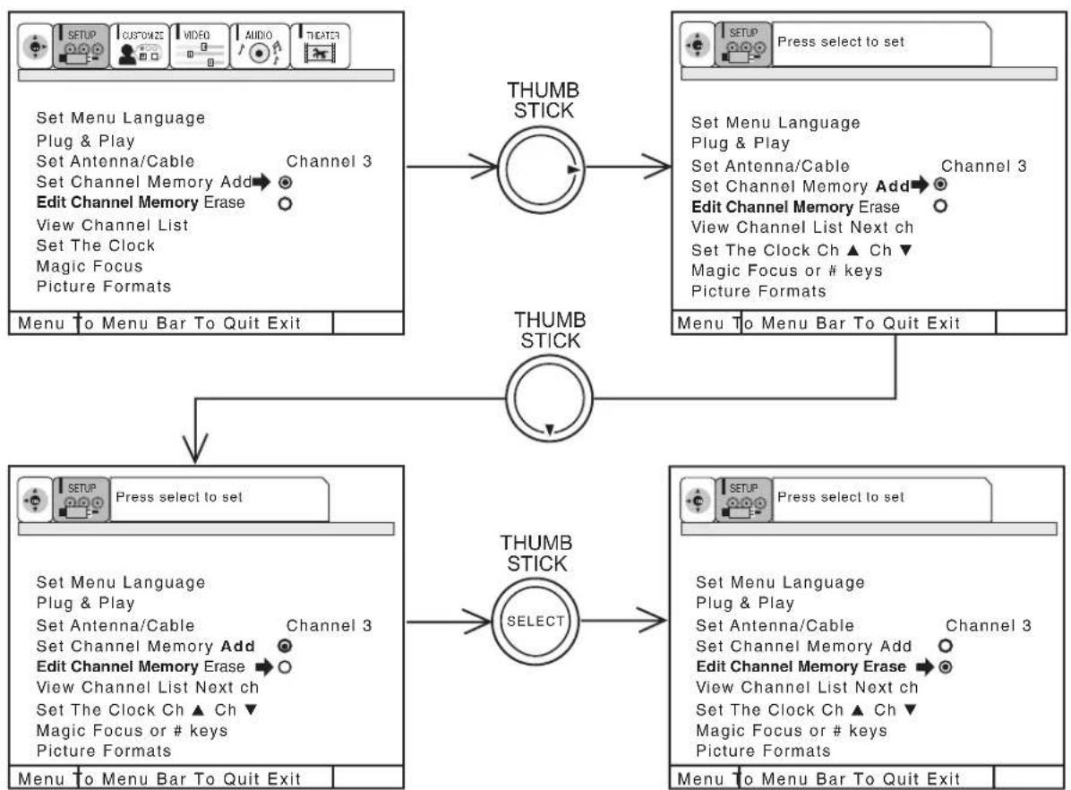
flowchart
graph TD
    A["SETUP"] --> B["SETU"]
    B --> C["Menu to Menu Bar To Quit Exit"]
    D["CUSTOMIZE"] --> E["Set Antenna/Cable"]
    E --> F["Set Channel Memory Add"]
    F --> G["Edit Channel Memory Erase"]
    G --> H["View Channel List"]
    H --> I["Set The Clock"]
    I --> J["Magic Focus"]
    J --> K["Picture Formats"]

    L["CVIDEO"] --> M["Set Antenna/Cable"]
    M --> N["Set Channel Memory Add"]
    N --> O["Edit Channel Memory Erase"]
    O --> P["View Channel List Next ch"]
    P --> Q["Set The Clock Ch ▲ Ch ▼"]
    Q --> R["Magic Focus or # keys"]
    R --> S["Picture Formats"]

    T["AUDIO"] --> U["Set Antenna/Cable"]
    U --> V["Set Channel Memory Add"]
    V --> W["Edit Channel Memory Erase"]
    W --> X["View Channel List Next ch"]
    X --> Y["Set The Clock Ch ▲ Ch ▼"]
    Y --> Z["Magic Focus or # keys"]
    Z --> AA["Picture Formats"]

    AB["THEATER"] --> AC["SETUP"] --> AD["Press select to set"]
    AE["THUMB STICK"] --> AF["THUMB STICK"]
    AG["THUMB STICK"] --> AH["THUMB STICK"]
    AI["THUMB STICK"] --> AJ["THUMB STICK"]
    AK["THUMB STICK"] --> AL["THUMB STICK"]

    AM["Menu to Menu Bar To Quit Exit"] --> AN["Menu to Menu Bar To Quit Exit"]
Add or erase additional channels while still in EDIT CHANNEL MEMORY using CHANNEL ▲ or ▼ or the number buttons to change the channel.
Press EXIT to quit menu or THUMB STICK ◀ to return to previous menu.
VIEW CHANNEL LIST
This function allows you to review which channels are labeled in NAME THE CHANNEL, which have been added to EDIT CHANNEL MEMORY (SCAN), and which are protected by SET PARENTAL LOCKS.
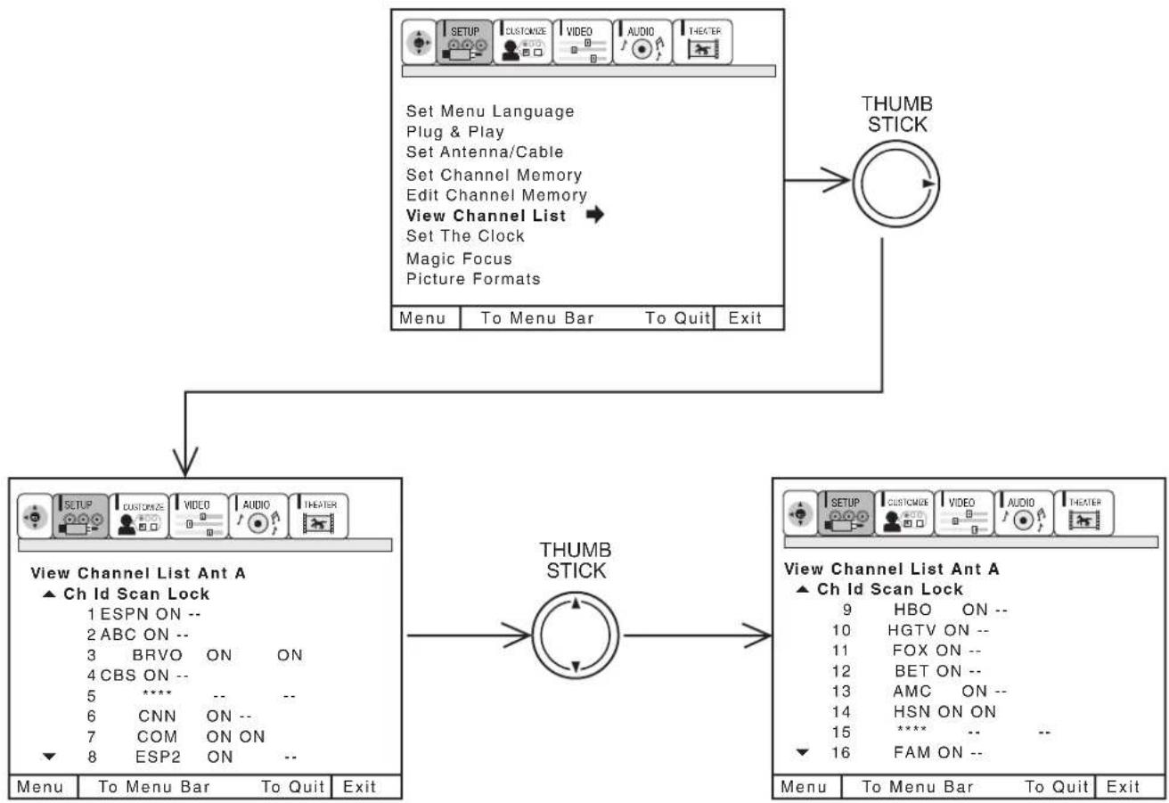
flowchart
graph TD
    A["Menu"] --> B["To Menu Bar"]
    B --> C["To Quit"]
    C --> D["Exit"]
    E["View Channel List Ant A ▲ Ch Id Scan Lock"] --> F["Menu"]
    F --> G["To Menu Bar"]
    G --> H["To Quit"]
    H --> I["Exit"]
    J["THUMB STICK"] --> K["Menu"]
    K --> L["To Menu Bar"]
    L --> M["To Quit"]
    M --> N["Exit"]
    O["Set Menu Language\nPlug & Play\nSet Antenna/Cable\nSet Channel Memory\nEdit Channel Memory\nView Channel List →\nSet The Clock\nMagic Focus\nPicture Formats"] --> P["THUMB STICK"]
    P --> Q["Menu"]
    Q --> R["To Menu Bar"]
    R --> S["To Quit"]
    S --> T["Exit"]
    U["SETUP"] --> V["CUSTOMER"]
    V --> W["VIDEO"]
    W --> X["AUDIO"]
    X --> Y["THEATER"]
    Z["TRAVEL"] --> AA["ON ON ON ON ON ON ON ON ON ON ON ON ON ON ON ON ON ON ON ON ON ON ON ON ON ON ON ON ON ON ON ON ON ON ON ON ON ON ON ON ON ON ON ON ON ON ON ON ON ON ON ON ON ON ON ON ON ON ON ON ON ON ON ON ON ON ON ON ON ON ON ON ON ON ON ON ON ON ON ON ON ON ON ON ON ON ON ON ON ON ON ON ON ON ON ON ON ON ON ON ON Non-Text In Table"]
Press THUMB STICK ▲ or ▼ to review more channels.
Press EXIT to quit menu or THUMB STICK ◀ to return to previous menu.
NOTE: Each touch of THUMB STICK ▲ or ▼ will display the next eight channels.
SET THE CLOCK
The time must be set before you can SET PROGRAM TIMER or TV TIME OUT.
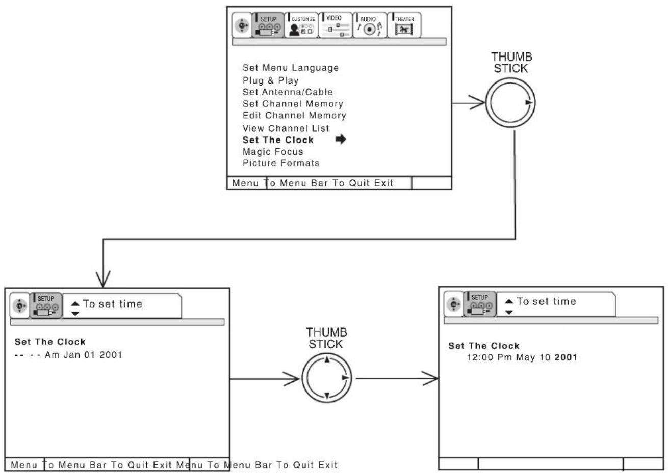
flowchart
graph TD
    A["SETUP CUSTOMIZE VIDEO AUDIO THEATER"] --> B["THUMB STICK"]
    B --> C["To set time"]
    C --> D["SET The Clock -- - Am Jan 01 2001"]
    D --> E["THUMB STICK"]
    E --> F["To set time"]
    F --> G["Set The Clock 12:00 Pm May 10 2001"]
    G --> H["Menu to Menu Bar To Quit Exit"]
    H --> I["Menu to Menu Bar To Quit Exit"]
    I --> J["Menu to Menu Bar To Quit Exit"]
Use THUMB STICK ▲ or ▼ to set the time, date, and year.
Press THUMB STICK ◀ or ▶ to change position.
Press EXIT to quit menu or THUMB STICK ◀ to return to previous menu when the CURSOR is in the first position.
MAGIC FOCUS
Please turn on your television for at least 20 minutes before using this feature.
Your HITACHI Projection TV has three color projection tubes: one for red, one for green, one for blue. When mixed together in the proper proportion, the output of these three color tubes can produce any color. To produce these colors, however, the beams must be precisely aligned over each other so that the colors can be mixed. The process of aligning these picture beams is called “convergence”.
Over a period of time, the picture tubes can drift out of alignment due to normal bumps and vibrations or moving the TV. If you move your TV, or if, after a time, you notice color rings or halos around objects in the picture, you may want to converge (align) the colors.
Properly converged, the lines appear white, which is actually a combination of the outputs of the three color tubes. The output of the green tube is stationary. The outputs of the red and blue tubes can be adjusted. When properly aligned, the outputs of all three tubes should be directly over each other to produce the white lines.
To simplify convergence, HITACHI incorporates a function called MAGIC FOCUS located on the front control panel, which allows the TV to self-adjust. Press this MAGIC FOCUS button and the convergence self adjustment will start and this process will take approximately 15 seconds. If this button is pressed during this process, no change in picture quality will occur. After this 15 second self-adjust period, picture quality will be optimum. (Do not move the TV during self-adjust.)
You may also select MAGIC FOCUS from the SETUP Menu.
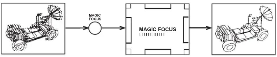
flowchart
graph LR
    A["Front View"] --> B["MAGIC FOCUS"]
    B --> C["MAGIC FOCUS"]
    C --> D["Next View"]
NOTES: 1. For Magic Focus to perform at it's best, the television must be turned "ON" and heat run for a minimum of 20 minutes before pressing Magic Focus on the front panel.
- Only a momentary press of the MAGIC FOCUS button is necessary to start AUTO DIGITAL CONVERGENCE. At anytime during this convergence correction process, you may press the MAGIC FOCUS button to exit the MAGIC FOCUS mode.
PICTURE FORMATS
The PICTURE FORMATS function is very useful when setting up reception High Definition, Standard Definition and NTSC signals.
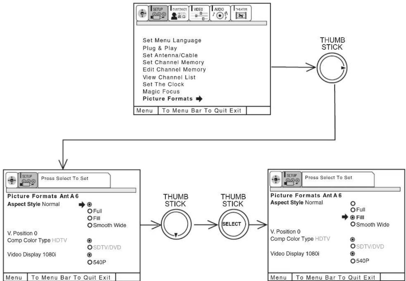
flowchart
graph TD
    A["Set Menu Language\nPlug & Play\nSet Antenna/Cable\nSet Channel Memory\nEdit Channel Memory\nView Channel List\nSet The Clock\nMagic Focus\nPicture Formats"] --> B["THUMB STICK"]
    B --> C["Picture Formats Ant A6\nAspect Style Normal\nFull\nFill\nSmooth Wide\nV. Position 0\nComp Color Type HDTV\nSDTV/DVD\nVideo Display 1080i\n540P"]
    C --> D["THUMB STICK"]
    D --> E["THUMB STICK SELECT"]
    E --> F["THUMB STICK"]
    F --> G["THUMB STICK"]
    G --> H["THUMB STICK"]
    H --> I["THUMB STICK"]
    I --> J["THUMB STICK"]
    J --> K["THUMB STICK"]
    K --> L["THUMB STICK"]
    L --> M["THUMB STICK"]
    M --> N["THUMB STICK"]
    N --> O["THUMB STICK"]
    O --> P["THUMB STICK"]
    P --> Q["THUMB STICK"]
    Q --> R["THUMB STICK"]
    R --> S["THUMB STICK"]
    S --> T["THUMB STICK"]
    T --> U["THUMB STICK"]
    U --> V["THUMB STICK"]
    V --> W["THUMB STICK"]
    W --> X["THUMB STICK"]
    X --> Y["THUMB STICK"]
    Y --> Z["THUMB STICK"]
    Z --> AA["THUMB STICK"]
    AA --> AB["THUMB STICK"]
    AB --> AC["THUMB STICK"]
    AC --> AD["THUMB STICK"]
    AD --> AE["THUMB STICK"]
    AE --> AF["THUMB STICK"]
    AF --> AG["THUMB STICK"]
    AG --> AH["THUMB STICK"]
    AH --> AI["THUMB STICK"]
    AI --> AJ["THUMB STICK"]
    AJ --> AK["THUMB STICK"]
    AK --> AL["THUMB STICK"]
    AL --> AM["THUMB STICK"]
    AM --> AN["THUMB STICK"]
    AN --> AO["THUMB STICK"]
    AO --> AP["THUMB STICK"]
    AP --> AQ["THUMB STICK"]
    AQ --> AR["THUMB STICK"]
    AR --> AS["THUMB STICK"]
    AS --> AT["THUMB STICK"]
    AT --> AU["THUMB STICK"]
    AU --> AV["THUMB STICK"]
    AV --> AW["THUMB STICK"]
    AW --> AX["THUMB STICK"]
    AX --> AY["THUMB STICK"]
ASPECT STYLE
If you receive an image with a 4:3 aspect ratio, the image will be displayed at that ratio on your HDTV unless you specify otherwise. The Picture Format menu allows you to adjust the image through the following options:
Normal Choose this when receiving a 4:3 image and you want the on-screen appearance of the video to be a centered picture with side panels (blank areas) on the right and left sides.
Full Choose this when you want the television to adjust the 4:3 image horizontally so it fills your 16:9 screen. No side panels will be added, and the image is vertically unaltered. This setting is especially useful for viewing 16:9 formatted DVDs.
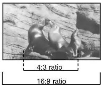
ASPECT STYLE
Fill This function allows you to select when receiving either NTSC or
SDTV. Full screen picture is available in this mode when receiving letterbox signal. Both vertical edges will be hidden if you select Fill for ordinary 4:3 picture.
Smooth Wide This function allows you to select when receiving either NTSC or SDTV signal. 4:3 picture is expanded horizontally as being close to both left and right sides. It keeps 4:3 ratio in the center of the picture, then expands as it is close to both left and right edge of the picture to show picture distortion minimized. This function allows you to watch picture without side panel for 4:3.
Some digital (ATSC format) stations may transmit 4:3 images in a way that will not allow expansion. You will be unable to adjust the picture format.
V. POSITION
This function allows you to select when aspect style is either Full or Fill or Smooth Wide. Vertical position can be changed with this mode. For example, it will be useful for centering the picture when there is gray area at both top and bottom of the picture with HDTV signal. Adjustable range is -10 (video center is toward bottom of screen) to +10 (video center is toward top of screen).
COMPONENT COLOR TYPE
This function allows you to automatically change tint and color coordinates for DTV programs.
HDTV - High Definition Television - Use for High Vision Signal Y-PRB from HDTV Set-Top Box.
SDTV /DVD - Standard Definition Television or DVD (Digital Versatile Disc Player) Y-CBCR.
VIDEO DISPLAY
The Video Display feature allows you to display 1080i or 540P signal modes. This feature selection is not available when 1080i signal is input.
NOTES: 1. The aspect Style setting you select for an ANT input will automatically be set for the other ANT input. However, all five video inputs have independent Aspect Style settings.
2. You will not be able to access the V. Position menu if Aspect Style-Normal is set.
3. You will only be able to access the Aspect Style menu when viewing a 4:3-480i or 480P. When viewing a 16:9-1080i or 720P input you will not be able to access this menu. FULL mode will be automatically selected
4. If COMPONENT COLOR TYPE is set improperly (does not match actual input signal), the color and tint of the main picture will be abnormal.
5. You must be tuned to VIDEO: 4 or 5 input and have a component hooked up to the Y-P _B PR input jacks to access this component color type.
6. All component color type settings will affect only color component input you are currently viewing. If you are using both sets of component input jacks, be sure to set the component color type feature for both inputs.
7. When 1080i signal is input, Video Display menu will not be accessible.
This selection contains advanced features which will make TV viewing easier and more enjoyable.
NAME THE CHANNEL
Use this feature to give up to 20 channels a name when ANTENNA signal source is selected and up to 60 channels a name when CATV signal source is selected.
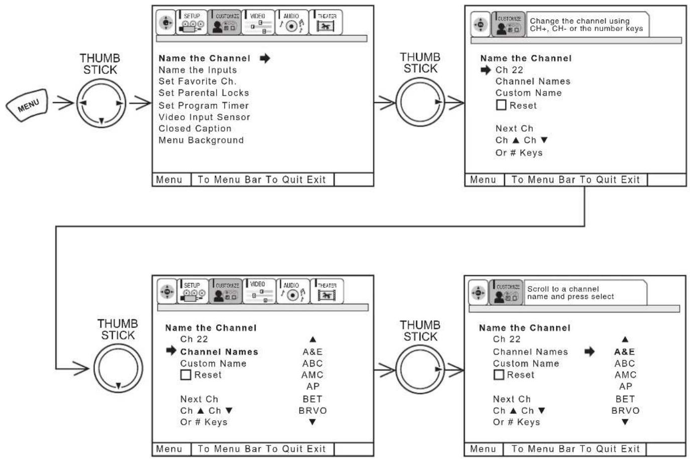
flowchart
graph TD
    A["MENU"] --> B["THUMB STICK"]
    B --> C["Menu: To Menu Bar To Quit Exit"]
    C --> D["THUMB STICK"]
    D --> E["Menu: To Menu Bar To Quit Exit"]
    E --> F["THUMB STICK"]
    F --> G["Menu: To Menu Bar To Quit Exit"]
    G --> H["THUMB STICK"]
    H --> I["Menu: To Menu Bar To Quit Exit"]
    I --> J["THUMB STICK"]
    J --> K["Menu: To Menu Bar To Quit Exit"]
    K --> L["THUMB STICK"]
    L --> M["Menu: To Menu Bar To Quit Exit"]
    M --> N["THUMB STICK"]
    N --> O["Menu: To Menu Bar To Quit Exit"]
    O --> P["THUMB STICK"]
    P --> Q["Menu: To Menu Bar To Quit Exit"]
    Q --> R["THUMB STICK"]
    R --> S["Menu: To Menu Bar To Quit Exit"]
    S --> T["THUMB STICK"]
    T --> U["Menu: To Menu Bar To Quit Exit"]
    U --> V["THUMB STICK"]
    V --> W["Menu: To Menu Bar To Quit Exit"]
    W --> X["THUMB STICK"]
    X --> Y["Menu: To Menu Bar To Quit Exit"]
    Y --> Z["THUMB STICK"]
Press THUMB STICK ▼ to highlight CHANNEL NAMES.
Press THUMB STICK ▶ to select preset CHANNEL NAMES.
Press THUMB STICK ▼ to scroll through the preset CHANNEL NAMES.
Press down on THUMB STICK to select desired CHANNEL NAME.
To customize CHANNEL NAMES, select CUSTOM NAME.
Press THUMB STICK ▲ or ▼ to select letter.
Press THUMB STICK ◀ or ▶ to change character position.
(★) represents a blank space.
Press CHANNEL ▲ or ▼ and the number buttons to label additional channels.
Press EXIT to quit menu or THUMB STICK ◀ to return to previous menu when the CURSOR is in the first position.
Select RESET to erase a CHANNEL NAMES.
NOTES: 1. If ANT A and ANT B are in the same ANTENNA/CABLE mode (see page 40), the CHANNEL NAMES for both antenna inputs will be the same.
- CHANNEL NAMES will be displayed only when channel is displayed as main picture.
NAME THE INPUTS
Use this feature to give a name to any of the five video inputs.
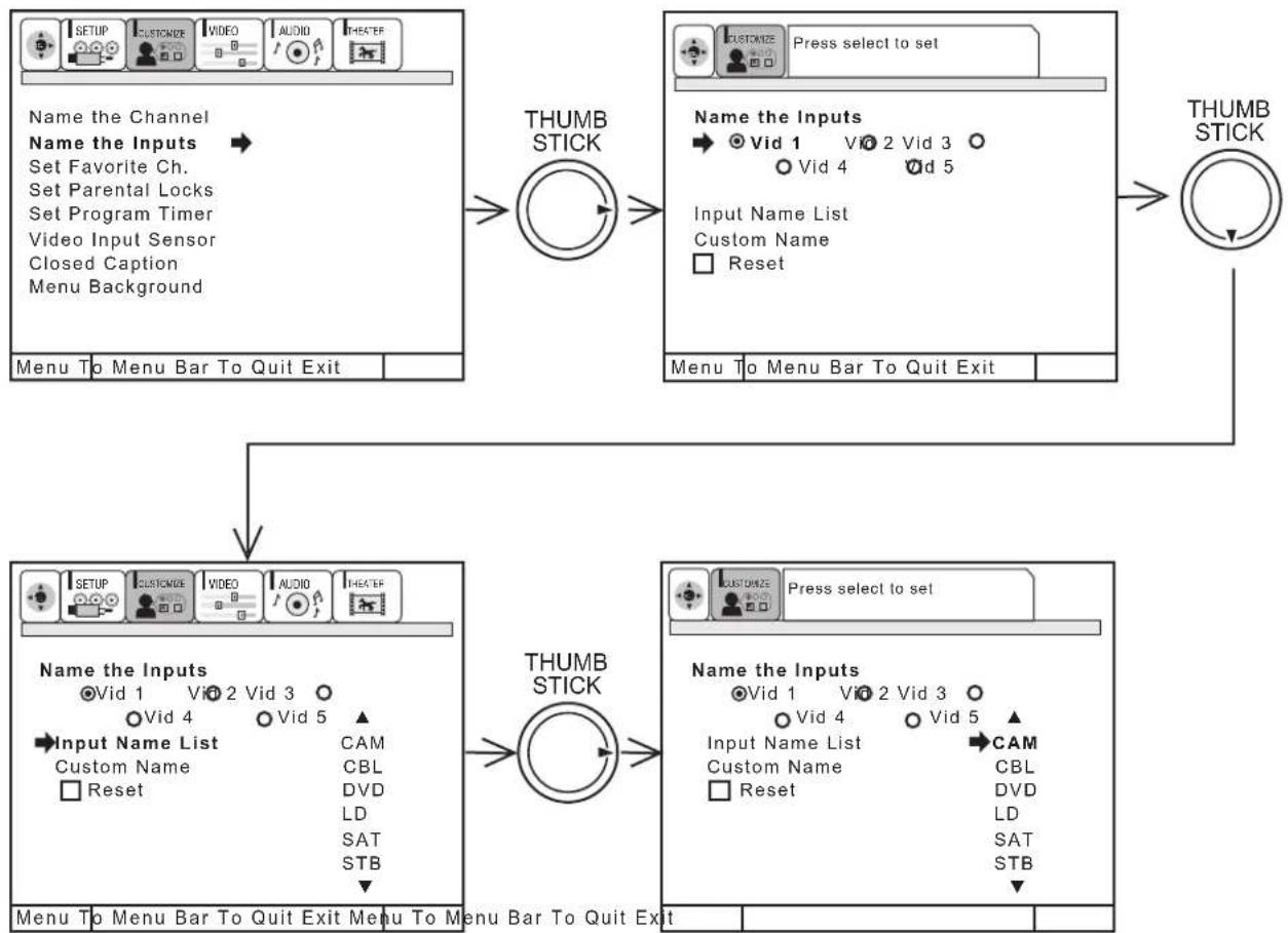
flowchart
graph TD
    A["Menu To Menu Bar To Quit Exit"] --> B["THUMB STICK"]
    B --> C["Menu To Menu Bar To Quit Exit"]
    C --> D["THUMB STICK"]
    D --> E["Menu To Menu Bar To Quit Exit"]

    subgraph Input_Inputs
        F1["Input Name List"] --> G1["Custom Name"]
        F2["Input Name List"] --> G2["DVD"]
        F3["Input Name List"] --> G3["LD"]
        F4["Input Name List"] --> G4["SAT"]
        F5["Input Name List"] --> G5["STB"]
    end

    subgraph Output_Inputs
        H1["Input Name List"] --> I1["CBL"]
        H2["Input Name List"] --> I2["DVD"]
        H3["Input Name List"] --> I3["LD"]
        H4["Input Name List"] --> I4["SAT"]
        H5["Input Name List"] --> I5["STB"]
    end

    F1 --> G1
    F2 --> G2
    F3 --> G3
    F4 --> G4
    F5 --> G5
    H1 --> I1
    H2 --> I2
    H3 --> I3
    H4 --> I4
    H5 --> I5
    I1 --> I2
    I2 --> I3
    I3 --> I4
    I4 --> I5
Press THUMB STICK ▼ to highlight NAME THE INPUTS.
Press THUMB STICK ▶ to select preset NAME THE INPUTS.
Press THUMB STICK ▲ or ▼ to scroll through the preset INPUT NAME LIST.
Press down on THUMB STICK to select desired INPUT NAME.
To customize INPUT NAME, select CUSTOM.
Press THUMB STICK ▶ to select the video input to be named.
Press THUMB STICK ▲ or ▼ to select letters.
Press THUMB STICK ▶ or ◀ to change position.
Press down on THUMB STICK to set.
Press EXIT to quit menu or THUMB STICK ◀ to return to previous menu when the CURSOR is in the first position.
(★) represents a blank space.
Select RESET to set INPUT NAMES to original condition.
NOTE: INPUT NAME will be displayed only when video INPUT is displayed as main picture.
SET FAVORITE CHANNELS
This function allows you to group your favorite channels into six personalized categories that you can rename. A total of 36 channels can be stored in the FAVORITE CHANNELS function.
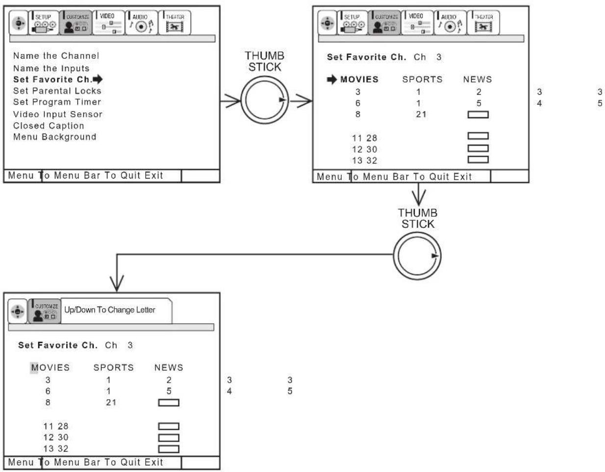
flowchart
graph TD
    A["Name the Channel\nName the Inputs\nSet Favorite Ch."] --> B["Menu To Menu Bar To Quit Exit"]
    B --> C["THUMB STICK"]
    C --> D["Set Favorite Ch. Ch 3\nMOVIES SPORTS NEWS\n3 1 2\n6 1 5\n8 21\n11 28\n12 30\n13 32"]
    D --> E["THUMB STICK"]
    E --> F["Up/Down To Change Letter"]
    F --> G["Set Favorite Ch. Ch 3\nMOVIES SPORTS NEWS\n3 1 2\n6 1 5\n8 21\n11 28\n12 30\n13 32"]
    G --> H["Menu To Menu Bar To Quit Exit"]
Channel stored with CHANNEL MEMORY will automatically be stored in FAVORITE CHANNELS.
To rename the categories, use the THUMB STICK to highlight the category you would like to rename.
Use THUMB STICK ▲ or ▼ to change a letter and THUMB STICK ▶ to select the next character to change.
To enter a channel into a category, highlight the channel location to be stored.
Press CHANNEL ▲ or ▼ or the number buttons to enter the desired channel. Repeat until category has been set with your favorite channels. The channel to be added is displayed in the top right corner of the screen.
Enter channel 00 to erase a favorite channel.
To reset categories and channels back to original factory preset, press STATUS while you are renaming a category.
NOTE:
- This function cannot be accessed when ANT B is the main channel.
- When the input source is not ANT A, the message "PLEASE SWITCH TO ANT A" will appear.
- Each category contains 2 groups of 3 channels, for a total of 6 channels per category.
FAVORITE CHANNELS (OPERATION)
Use this function to display FAVORITE CHANNEL selections as sub-pictures or to tune the main picture to a desired favorite channel.
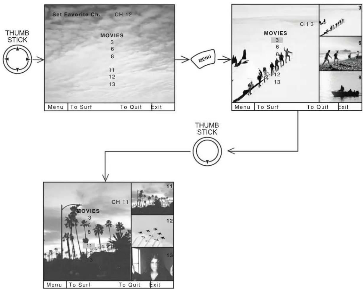
flowchart
graph TD
    A["THUMB STICK"] --> B["Set Favorite Ch. CH 12"]
    B --> C["MOVIES"]
    C --> D["Menu: To Surf To Quit Exit"]
    D --> E["Menu: To Surf To Quit Exit"]
    E --> F["THUMB STICK"]
    F --> G["MOVIES"]
    G --> H["Menu: To Surf To Quit Exit"]
    H --> I["Menu: To Surf To Quit Exit"]
    I --> J["Menu: To Surf To Quit Exit"]
Select a category using THUMB STICK ◀ or ▶.
Press MENU and the category will be displayed as sub-pictures at the right edge of the screen. This is useful for previewing a category.
Use THUMB STICK ◀, ▶, ▲ or ▼ to highlight a favorite channel and the TV will automatically tune to that channel.
Press EXIT to remove FAVORITE CHANNELS OSD from the screen.
NOTE:
- If a category has some blank channel entries, these channels will appear as black sub-pictures.
- Each category contains 2 groups of 3 channels. Pressing the MENU button will display only 1 group per category, depending on which group you select.
- When CLOSED CAPTION is set to AUTO and MUTE is ON, FAVORITE CHANNEL can not be accessed.
SET PARENTAL LOCKS
This function will block out the picture and sound of the selected channel or video input. It can also be used to keep the TV from being viewed for a scheduled amount of time that you set.
The code to enter SET PARENTAL LOCKS is a four digit secret code number. The factory preset code is 0000. Use the number buttons to select secret code.
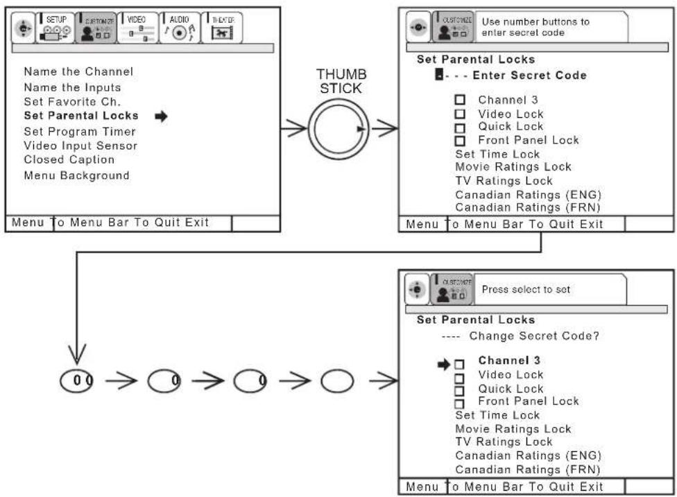
flowchart
graph TD
    A["Name the Channel\nName the Inputs\nSet Favorite Ch.\nSet Parental Locks\nSet Program Timer\nVideo Input Sensor\nClosed Caption\nMenu Background"] --> B["THUMB STICK"]
    B --> C["Set Parental Locks\n- - - Enter Secret Code\nChannel 3\nVideo Lock\nQuick Lock\nFront Panel Lock\nSet Time Lock\nMovie Ratings Lock\nTV Ratings Lock\nCanadian Ratings (ENG)\nCanadian Ratings (FRN)"]
    C --> D["Menu to Menu Bar To Quit Exit"]
    D --> E["0 0 → 0 → 0 → 0 →"]
    E --> F["Press select to set\nSet Parental Locks\n---- Change Secret Code?\nChannel 3\nVideo Lock\nQuick Lock\nFront Panel Lock\nSet Time Lock\nMovie Ratings Lock\nTV Ratings Lock\nCanadian Ratings (ENG)\nCanadian Ratings (FRN)"]
    F --> G["Menu to Menu Bar To Quit Exit"]
Use THUMB STICK ▲ or ▼ to highlight function and press down on the THUMB STICK to set ON or OFF.
When CHANNEL is turned on, the picture and sound for the chosen channel will be blocked out.
When VIDEO LOCK is turned on, the picture and sound for all video inputs will be blocked out. To lock the video inputs, you must be tuned to one of the video inputs.
When QUICK LOCK is turned on, the picture and sound for channels 3, 4 on both ANT A/B and all video inputs will be blocked out.
When FRONT PANEL LOCK is turned on, all buttons on the Front Panel will be deactivated, except the POWER button.
When SET TIME LOCK is turned on, you can set the BEGIN and END times and the TV cannot be viewed during that time period. (Set clock first.) Use THUMB STICK ▲ or ▼ to highlight ONCE (TV will time out one time only), DAILY (TV will time out every day), WEEKLY (TV will time out one time a week) or OFF (to disable this function) and then press down on THUMB STICK to SELECT your choice.
MOVIE RATINGS LOCK, TV RATINGS LOCK, and CANADIAN RATINGS are explained in detail in the Parental Control Movie/TV Ratings Reference Guide.
To change the secret code number, select CHANGE SECRET CODE. Enter a new four digit key number you prefer.
If you forget your secret code, use the factory code 7777 to erase your key number. This will reset the secret code number back to the factory preset 0000.
Press EXIT to quit menu or THUMB STICK ◀ to return to previous menu.
NOTE: 1. If ANT A and ANT B are in the same signal source mode (see page 40), when a channel is locked, it is locked on both antenna inputs.
- When using SET TIME LOCK make sure the clock is set (see page 44).
- Text appears on the screen to indicate that TV TIMED OUT (Set Parental Locks) is activated.
SET PROGRAM TIMER
This function will automatically turn the TV on and off, one time only, every day, or once a week.
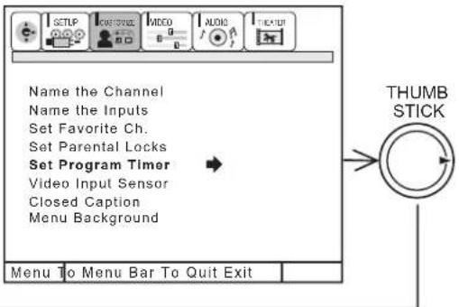
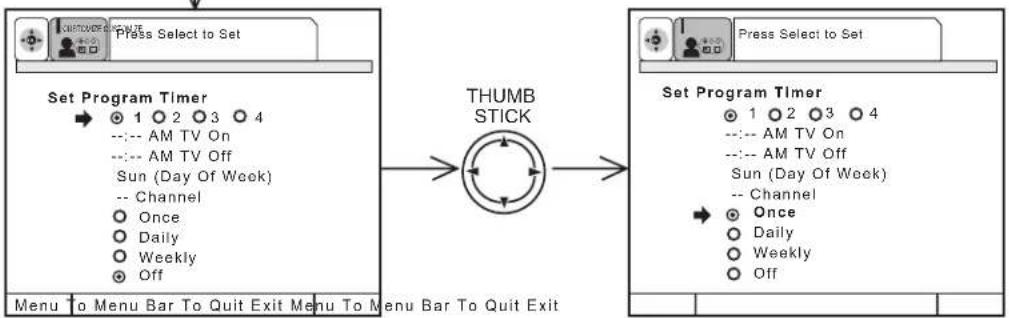
flowchart
graph LR
    A["Set Program Timer"] --> B["THUMB STICK"]
    B --> C["Set Program Timer"]
    C --> D["Menu to Menu Bar To Quit Exit"]
    style A fill:#f9f,stroke:#333
    style B fill:#ccf,stroke:#333
    style C fill:#cfc,stroke:#333
    style D fill:#fcc,stroke:#333
Use THUMB STICK ▶ to select PROGRAM 1, 2, 3, or 4.
Use THUMB STICK ▲ or ▼ to select the time the TV will turn on and off.
Use THUMB STICK ▶ to change position.
Use THUMB STICK ▲ or ▼ to select the day of the week you want the timer to turn on TV. (If you set timer to turn on DAILY, do not need to set DAY OF WEEK).
Use THUMB STICK ▲ or ▼, CHANNEL (▲) or (▼), or number buttons to set the channel the TV will tune to when it automatically turns on.
Use THUMB STICK ▲ or ▼ to highlight, then press down on the THUMB STICK to select mode ONCE (TV will turn on/off one time only), or mode DAILY (TV will turn on/off at the same time every day), WEEKLY (TV will turn on/off at same time every week) or OFF (to disable this function).
Press EXIT to quit menu or THUMB STICK ◀ to return to previous menu.
If the clock is not set, you can not use this function and the screen below will appear.
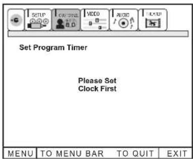
NOTE:
- The OFF Timer will only activate if the TV was turned on or tuned with the ON Timer and no channel selection was made after this time. If you change the channel after the ON Timer has been activated, the OFF Timer will deactivate.
- If no remote control button is pressed after ON Timer is activated, the TV will automatically turn off after three hours.

CAUTION: Do not use your TV as a deterrent when away from home by using the ON and OFF TIMERS. For safety, the TV should be turned off when you are away from home.
VIDEO INPUT SENSOR
Use this function to automatically turn the TV on and tune to VIDEO: 4 when it detects a VIDEO input.
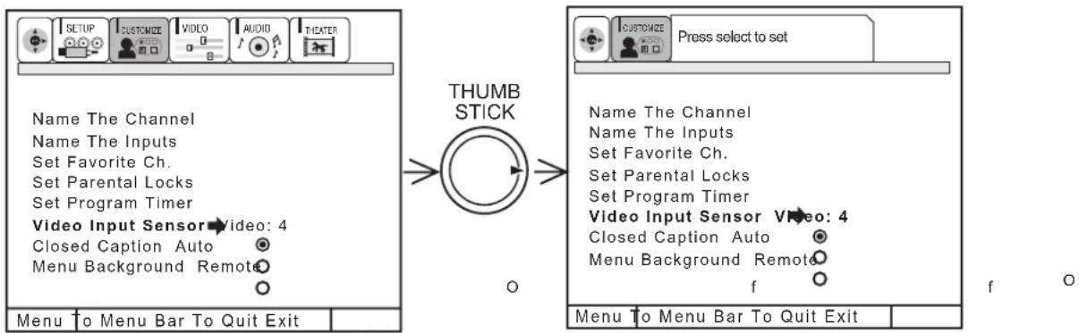
Use THUMB STICK ▲ or ▼, then press down on THUMB STICK to change VIDEO INPUT SENSOR setting.
When AUTO is selected, the TV will turn on and tune to VIDEO: 4 automatically, when the VIDEO: 4 input device is turned on. This is convenient when you want to watch a movie with your VCR, laserdisc player, or DVD player.
When REMOTE is selected, the TV will turn on and tune to VIDEO: 4 automatically, when the VIDEO: 4 input device is turned on and the VCR, laserdisc, or DVD play button on your remote control is pressed.
This is convenient when you want to record a movie with your VCR and watch it later.
Select OFF to disable this function.
Press EXIT to quit menu or THUMB STICK ◀ to return to previous menu.
NOTES: 1. Once the TV has been turned on using the VIDEO INPUT SENSOR feature, it must be reset before VIDEO INPUT SENSOR is used again. To do this, turn your VCR, laserdisc, or DVD player OFF. This feature is now reset and will turn on your TV as described above.
2. When using REMOTE mode, any remote control button will substitute for your video input device play button. However, intended operation is for use with your VCR, laserdisc, or DVD play button.
3. If no remote control button is pressed after the TV is turned on by VIDEO INPUT SENSOR, the TV will automatically turn off after three hours.
CLOSED CAPTION
Closed Captions are the dialogue, narration, and/or sound effects of a television program or home video which are displayed on the TV screen. Your local TV program guide denotes these programs as cc or

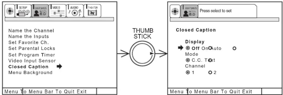
flowchart
graph LR
    A["SETUP"] --> B["CUSTOMIZE"]
    B --> C["VIDEO"]
    C --> D["AUDIO"]
    D --> E["THEATER"]
    F["Menu To Menu Bar To Quit Exit"] --> G["THUMB STICK"]
    G --> H["Closed Caption"]
    H --> I["Display: Off On Auto Mode C.C. Text Channel 1 2"]
    J["Press select to set"] --> K["Customize"]
    K --> L["Menu To Menu Bar To Quit Exit"]
DISPLAY: ON/OFF will turn the display or off.
AUTO will turn the display on when Mute/Soft Mute is on.
MODE: C.C. (Closed Caption) is for the program you are viewing.
TEXT is for additional information such as news reports or a TV program guide. This information covers the entire screen and viewing the TV program is not possible. TEXT may not be available with every program.
CHANNEL: 1 is used for the primary language (usually English).
2 is sometimes used for a second language (may vary by region).
Use THUMB STICK ▲, ▼ to highlight the function to change then press THUMB STICK to change the function.
Press EXIT to quit menu or THUMB STICK ◀ to return to previous menu.
NOTE: 1. CLOSED CAPTION will not work when viewing a 480P, 720P, or 1080i input via the COMPONENT: Y-P B P R inputs.
- When PIP Surf is on, Closed Caption will not work.
MENU BACKGROUND
This function allows you to choose from two menu backgrounds.
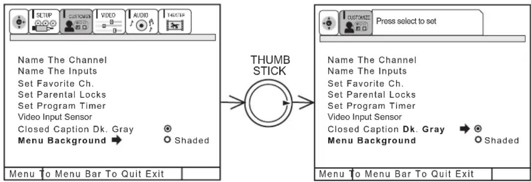
Use THUMB STICK ▲ or ▼ to highlight MENU BACKGROUND setting, and press down on THUMB STICK to select setting.
Press EXIT to quit menu or THUMB STICK ◀ to return to previous menu.
Select DARK GRAY and a dark gray background is visible (no picture can be seen behind menu screen), select SHADED and a light background is visible.
Select VIDEO to adjust picture settings and improve picture quality.

flowchart
graph LR
    A["MENU"] --> B["THUMB STICK"]
    B --> C["Contrast 100%"]
    B --> D["Brightness 50%"]
    B --> E["Color 50%"]
    B --> F["Tint 50%"]
    B --> G["Sharpness 50%"]
    B --> H["Reset 50%"]
    B --> I["Advanced Settings"]
    C --> J["THUMB STICK"]
    J --> K["Contrast 100%"]
    K --> L["Menu To Menu Bar To Quit Exit"]
Use the THUMB STICK ▲ or ▼ to highlight the function to be adjusted.
Press the THUMB STICK ◀ or ▶ to adjust the function.
Press EXIT to quit menu.
NOTE: If CONTRAST is selected, you are adjusting CONTRAST. The additional menu items BRIGHTNESS, COLOR, TINT, and SHARPNESS can be selected and adjusted in the same manner.
CONTRAST
Use this function to change the contrast between black and white levels in the picture. This adjustment will only affect the picture when ADVANCED SETTINGS PERFECT PICTURE is OFF. (see page 57)
BRIGHTNESS
Use this function to adjust overall picture brightness.
COLOR
Use this function to adjust the level of color in the picture.
TINT
Use this function to adjust flesh tones so they appear natural.
SHARPNESS
Use this function to adjust the amount of fine detail in the picture.
RESET
When RESET is selected, press down on THUMB STICK to return video adjustments to factory preset conditions.
NOTE: 1. It may be necessary to adjust TINT to obtain optimum picture quality when using the COMPONENT VIDEO Y-P B P R input jacks.
- If you are using the COMPONENT VIDEO input jacks (Y-PBPR) and notice that the TINT and COLOR are abnormal, check to make sure that Picture Formats - Component Color Type is set properly. (see page 47)
ADVANCED SETTINGS
Your HITACHI Projection TV has a PERFECT PICTURE function which will automatically adjust picture settings to produce the highest quality picture possible.
When PERFECT PICTURE is highlighted, press down on THUMB STICK to turn the PERFECT PICTURE on or off.
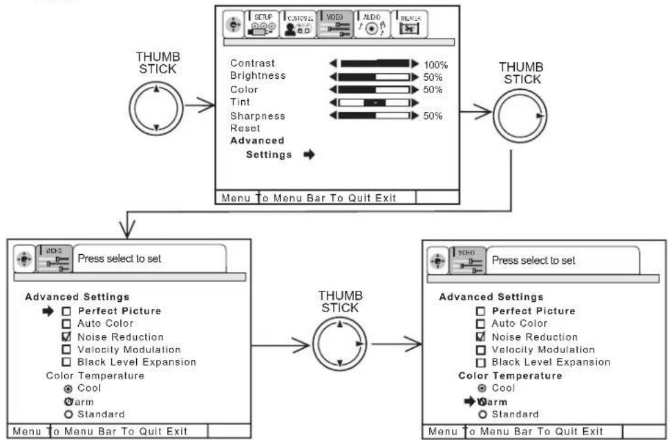
flowchart
graph TD
    A["THUMB STICK"] --> B["Menu to Menu Bar To Quit Exit"]
    B --> C["THUMB STICK"]
    C --> D["Press select to set"]
    D --> E["Advanced Settings"]
    E --> F["Menu to Menu Bar To Quit Exit"]
    F --> G["THUMB STICK"]
    G --> H["Press select to set"]
    H --> I["Advanced Settings"]
    I --> J["Menu to Menu Bar To Quit Exit"]
Use THUMB STICK ▲ or ▼ to select function.
Press down on THUMB STICK to select the function setting. When the function has an "in the box, it is ON.
Press down on THUMB STICK to change COLOR TEMPERATURE setting. When the function shows a “◦”, it is selected.
Press EXIT to quit menu or THUMB STICK ◀ to return to previous menu.
PERFECT PICTURE
When the PERFECT PICTURE function is on, the TVs' internal computer will perform the following:
-
Automatically monitor and adjust contrast depending on room lighting (sensor is located in the front panel) to produce a more natural picture.
-
Automatically monitor and adjust color levels and maintain natural flesh tones.
-
Automatically compensate for weak or strong TV signals to produce a clear picture.
Turn the PERFECT PICTURE function off to control other PREFERENCE SETTINGS.
AUTO COLOR
The AUTO COLOR function automatically monitors and adjusts the color to maintain constant color levels even after a program or channel changes. It also maintains natural flesh tones while preserving fidelity of background colors. (This function will automatically set to on and cannot be turned off when the PERFECT PICTURE function is ON.)
NOISE REDUCTION
The NOISE REDUCTION function automatically reduces conspicuous noise in the picture without degrading picture quality. (This function will automatically be set to on and cannot be turned off when the PERFECT PICTURE function is ON.)
VELOCITY MODULATION
The VELOCITY MODULATION function automatically enhances the edges between light and dark areas.
Set this to WARM for hotter colors with more red, set to COOL for less intense colors with more blue, or set to STANDARD for standard color.
Models: 61UWX10BA, 53UWX10BA, 43UWX10B
Select AUDIO to adjust the TV to your preference and to improve the sound quality.
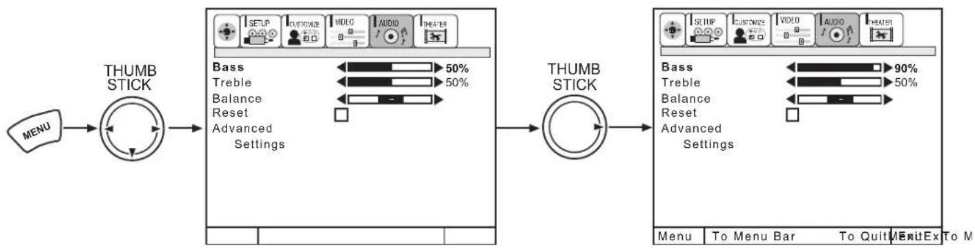
flowchart
graph LR
    A["MENU"] --> B["THUMB STICK"]
    B --> C["Bass 50% Treble Balance Reset Advanced Settings"]
    C --> D["THUMB STICK"]
    D --> E["Bass 90% Treble Balance Reset Advanced Settings"]
    E --> F["Menu To Menu Bar To Quit ExitTo M"]
Use THUMB STICK ▲ or ▼ to highlight the function to be adjusted.
Press THUMB STICK ◀ or ▶ to adjust the function.
Press EXIT to quit MENU.
NOTE: If BASS is selected you are adjusting BASS. The additional menu items TREBLE and BALANCE can be selected and adjusted in the same manner.
BASS
This function controls the low frequency audio to all speakers.
TREBLE
This function controls the high frequency audio to all speakers.
BALANCE
This function will control the left to right balance of the TV internal speakers and the AUDIO TO HI FI output.
RESET
When RESET is selected, press CURSOR ▶ to return audio adjustments to factory preset conditions.
Models: 61UWX10BA, 53UWX10BA, 43UWX10B
ADVANCED SETTINGS
Use ADVANCED SETTINGS to improve the sound performance of your TV, depending on listening conditions.
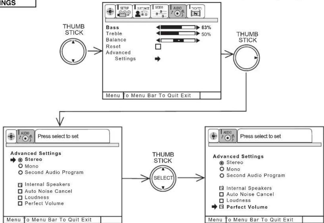
flowchart
graph TD
    A["THUMB STICK"] --> B["Press select to set"]
    B --> C["Advanced Settings"]
    C --> D["Select"]
    D --> E["THUMB STICK"]
    E --> F["Menu to Menu Bar To Quit Exit"]
    G["Bass 63%"] --> H["Bass"]
    I["Treble 50%"] --> J["Treble"]
    K["Balance"] --> L["Balance"]
    M["Reset"] --> N["Reset"]
    O["Advanced Settings"] --> P["Stereo Mono Second Audio Program Internal Speakers Auto Noise Cancel Loudness Perfect Volume"]
    Q["THUMB STICK"] --> R["Audio Press select to set"]
    R --> S["Advanced Settings"]
    S --> T["Stereo Mono Second Audio Program Internal Speakers Auto Noise Cancel Loudness Perfect Volume"]
    U["THUMB STICK"] --> V["Menu to Menu Bar To Quit Exit"]
Press THUMB STICK ▲ or ▼ to highlight a function. Press down on THUMB STICK to change the function setting. When the function has an “√” in the box, it is ON.
MTS MODE
Multi-Channel Television Sound will allow you to select STEREO (a stereo broadcast), MONO (monaural sound) used when receiving a weak stereo broadcast or SAP (second audio program) which may be a secondary language, weather report, etc. The sources received will be displayed at the top center edge of the TV. The source you select will be displayed above the sources received. See example below for each selection when both stereo and second audio are received (monaural is always received).
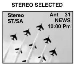
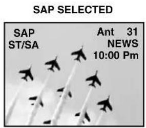
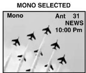
INTERNAL SPEAKERS
This function is useful when first setting up the external speakers, or if you prefer to use only speakers from a separate stereo system.
AUTO NOISE CANCEL
This function eliminates the noise between stations. If a channel is tuned and is noisy, this function will automatically eliminate the audio for that channel.
LOUDNESS
This function will improve the quality of both low and high frequency sounds when listening at low volume levels.
PERFECT VOLUME
This function will automatically adjust volume so each channel has the same average volume level.
Select AUDIO to adjust the TV to your preference and to improve the sound quality.
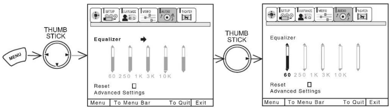
flowchart
graph LR
    A["MENU"] --> B["THUMB STICK"]
    B --> C["Equalizer"]
    C --> D["60 250 1K 3K 10K"]
    D --> E["Reset Advanced Settings"]
    E --> F["THUMB STICK"]
    F --> G["60 250 1K 3K 10K"]
    G --> H["Reset Advanced Settings"]
Use THUMB STICK ▲ or ▼ to highlight the function to be adjusted.
When EQUALIZER is highlighted, press THUMB STICK ▶ to select the frequency you would like to adjust (60, 250, 1K, 3K or 10K).
Then use THUMB STICK ▲ or ▼ to adjust selected frequency.
When RESET is highlighted, press down on THUMB STICK to reset EQUALIZER settings to factory conditions.
Press EXIT to quit menu.
NOTE: When DYNAMIC BASS is turned ON, the 60Hz level signal will automatically be increased.
Use ADVANCED SETTINGS to improve the sound performance of your TV, depending on listening conditions.
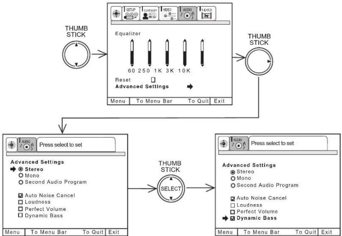
flowchart
graph TD
    A["THUMB STICK"] --> B["Equalizer"]
    B --> C["THUMB STICK"]
    C --> D["Press select to set"]
    D --> E["Advanced Settings"]
    E --> F["Select"]
    F --> G["THUMB STICK"]
    G --> H["Menu To Menu Bar To Quit Exit"]
    style A fill:#f9f,stroke:#333
    style C fill:#ccf,stroke:#333
    style D fill:#cfc,stroke:#333
    style E fill:#fcc,stroke:#333
    style F fill:#cff,stroke:#333
    style G fill:#ffc,stroke:#333
Press THUMB STICK ▲ or ▼ to highlight a function. Press down on THUMB STICK to change the function setting. When the function has a “√” in the box it is ON, when it has a “○” it is selected.
MTS MODE
Multi-Channel Television Sound will allow you to select STEREO (a stereo broadcast), MONO (monaural sound) used when receiving a weak stereo broadcast or SAP (second audio program) which may be a secondary language, weather report, etc.
The sources received will be displayed at the top center edge of the TV. The source you select will be displayed above the sources received. See example below for each selection when both stereo and second audio are received (monaural is always received).
STEREO SELECTED
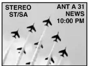
SAP SELECTED
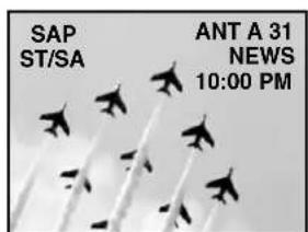
MONO SELECTED
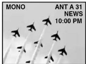
AUTO NOISE CANCEL
This function eliminates the noise between stations. If a channel is tuned and is noisy, this function will automatically eliminate the audio for that channel.
LOUDNESS
This function will improve the quality of both low and high frequency sounds when listening at low volume levels.
PERFECT VOLUME
This function will automatically adjust volume so each channel has the same average volume level. This function will automatically be disabled when SURROUND PRO LOGIC or SURROUND DOLBY DIGITAL are selected, or DIGITAL AUDIO is input, to ensure correct SURROUND sound decoding. (See pages 65-67)
DYNAMIC BASS
This function allows you to enjoy spectacular bass sound that would normally be heard only with expensive home speaker systems.
Models: 61UWX10BA, 53UWX10BA,
43UWX10B
Use this function to choose picture and audio settings for a true home THEATER experience.
THEATER MODES
Use this function to choose from automatic picture settings to optimize your TV's performance.
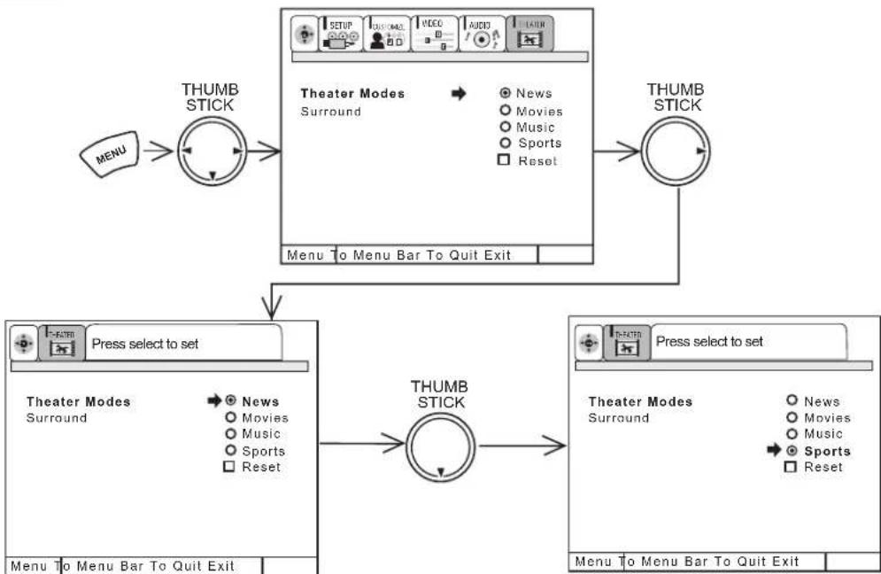
flowchart
graph TD
    A["THUMB STICK"] --> B["Theater Modes Surround"]
    B --> C["Menu to Menu Bar To Quit Exit"]
    C --> D["THUMB STICK"]
    D --> E["Press select to set"]
    E --> F["Thunder Mode Surround"]
    F --> G["Menu to Menu Bar To Quit Exit"]
    G --> H["THUMB STICK"]
    H --> I["Press select to set"]
    I --> J["Thunder Mode Surround"]
    J --> K["Menu to Menu Bar To Quit Exit"]
Use THUMB STICK ▲ or ▼ to change THEATER MODES settings.
When NEWS mode is chosen, the following are automatically set:
CONTRAST - 75%, COLOR TEMPERATURE - WARM, LOUDNESS - ON, PERFECT VOLUME - ON.
When MOVIES mode is chosen, the following are automatically set:
CONTRAST - 60%, COLOR TEMPERATURE - STANDARD, BASS - 63%, LOUDNESS - OFF, PERFECT VOLUME - OFF,SURROUND - SRS.
NOTE: MOVIE MODE 3:2 PULLDOWN DETECTION SPECIAL FEATURE
Theatrical movies are shot on film at 24 frames or still pictures per second, instead of 30 frames or 60 fields like video. When film is transferred to video for television viewing, the disparity between the two frame rates must be reconciled. This involves a process known as 3:2 pulldown.
When MOVIE MODE is selected from the THEATER menu, your Hitachi Projection Television will activate the circuitry for this special feature to improve video performance when watching film based sources. This 3:2 pulldown detection will only work in MOVIE MODE.
When MUSIC mode is chosen, the following are automatically set:
CONTRAST - 75%, COLOR TEMPERATURE - COOL, LOUDNESS - OFF, PERFECT VOLUME - OFF, SURROUND - SRS and BBE.
When SPORTS mode is chosen, the following are automatically set:
CONTRAST - 100%, COLOR TEMPERATURE - COOL, BASS - 63%, LOUDNESS - OFF, PERFECT VOLUME - OFF,SURROUND - SRS.
You can customize each of the above modes (NEWS, MOVIE, MUSIC and SPORTS) to your preference to increase viewing performance and pleasure, depending upon the video program being viewed. However, if RESET is selected, all modes will reset to the initial conditions as explained above.
When RESET is selected, it will take approximately two seconds to return to factory conditions (SPORTS mode).
Press EXIT to quit menu or THUMB STICK ◀ to return to previous menu.
Models: 61UWX10BA, 53UWX10BA,
43UWX10B
Surround
The following surround settings will reproduce the “live” sound you would hear in concert halls, sports stadiums, movie theaters, etc. with only two speakers.
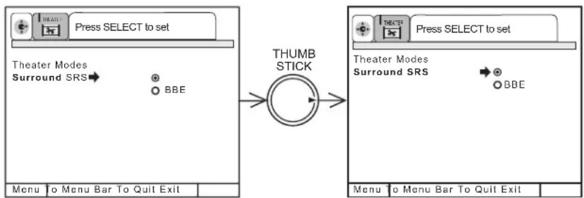
flowchart
graph LR
    A["Press SELECT to set"] --> B["Theater Modes Surround SRS"]
    B --> C["THUMB STICK"]
    C --> D["Press SELECT to set"]
    D --> E["Theater Modes Surround SRS"]
    E --> F["BBE"]
    G["Menu to Menu Bar To Quit Exit"] --> H["Menu to Menu Bar To Quit Exit"]
To enter the SURROUND MODE, use THUMB STICK ▲ or ▼ to highlight then press down on THUMB STICK to select SURROUND MODE of your choice.
SURROUND OFF
Use this for normal stereo/mono broadcasts.
SRS
by SRS(●)\*
Based on the principles of the human hearing system, SRS technology delivers and exciting and realistic 3D Sound experience from just two external speakers (or) the two internal speakers of your HITACHI Television. If your HITACHI Television is connected to an external audio system, SRS will also create an incredible 3D sound experience from two speakers and even enhance a complete multi-speaker surround sound system.
NOTES: *SRS and the (●) symbol are registered trademarks of SRS Labs, Inc. in the United States and selected foreign countries. SRS technology is incorporated under license from SRS Labs, Inc.
BBE Technology
Sound reproduction quality enhancement system. The BBE technology produces sound that is natural and crisp from just two speakers (or) the two internal speakers of your HITACHI television. If your HITACHI television is connected to an external audio system, BBE will also create an incredible crisp sound experience from two speakers and even more complete and accurate reproduction of the original performance. BBE brings to the listener's ear a more complete and accurate reproduction of the original performance. Each voice, speaking or singing, each instrument or sound effect is presented with its attendant harmonics or partials more clearly audible. The ear can then more easily recognize the unique tonal colors of each sound as though the sound was being produced live.
NOTES: BBE functions the same manner on TV mode and on VIDEO mode.
NOTES: Licensed by BBE Sound, Inc. under USP4638258 and 4482866. BBE and BBE symbol are registered trademarks of BBE Sound, Inc. Manufactured under license from BBE Sound, Inc.
Use this function to choose picture and audio settings for a true home THEATER experience.
THEATER MODES
Use this function to choose from automatic picture settings to optimize your TV's performance.
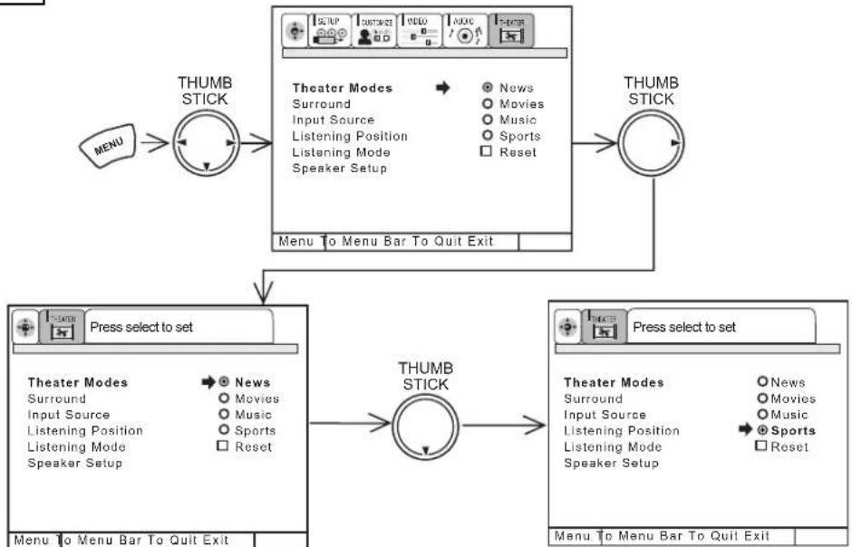
flowchart
graph TD
    A["Menu"] --> B["THUMB STICK"]
    B --> C["Theater Modes"]
    C --> D["Surround"]
    C --> E["Input Source"]
    C --> F["Listening Position"]
    C --> G["Listening Mode"]
    C --> H["Speaker Setup"]
    D --> I["News"]
    E --> J["Movies"]
    F --> K["Music"]
    G --> L["Sports"]
    H --> M["Reset"]
    N["Menu to Menu Bar To Quit Exit"] --> O["THUMB STICK"]
    O --> P["Press select to set"]
    P --> Q["Thunder Modes"]
    Q --> R["Surround"]
    Q --> S["Input Source"]
    Q --> T["Listening Position"]
    Q --> U["Listening Mode"]
    Q --> V["Speaker Setup"]
    W["THUMB STICK"] --> X["Press select to set"]
    X --> Y["Theater Modes"]
    Y --> Z["Surround"]
    Y --> AA["Input Source"]
    Y --> AB["Listening Position"]
    Y --> AC["Listening Mode"]
    Y --> AD["Speaker Setup"]
    AE["Menu to Menu Bar To Quit Exit"] --> AF["THUMB STICK"]
    AF --> AG["Press select to set"]
    AG --> AH["Thunder Modes"]
    AH --> AI["Surround"]
    AH --> AJ["Input Source"]
    AH --> AK["Listening Position"]
    AH --> AL["Listening Mode"]
    AH --> AM["Speaker Setup"]
    AN["Menu to Menu Bar To Quit Exit"] --> AO["THUMB STICK"]
Use THUMB STICK ▲ or ▼ to change THEATER MODES settings.
When NEWS mode is chosen, the following are automatically set:
CONTRAST - 75%, COLOR TEMPERATURE - WARM, LOUDNESS - ON, PERFECT VOLUME - ON.
When MOVIES mode is chosen, the following are automatically set:
CONTRAST - 60%, COLOR TEMPERATURE - STANDARD, BASS - 63%, LOUDNESS - OFF, PERFECT VOLUME - OFF, SURROUND - SRS.
NOTE: MOVIE MODE 3:2 PULLDOWN DETECTION SPECIAL FEATURE
Theatrical movies are shot on film at 24 frames or still pictures per second, instead of 30 frames or 60 fields like video. When film is transferred to video for television viewing, the disparity between the two frame rates must be reconciled. This involves a process known as 3:2 pulldown.
When MOVIE MODE is selected from the THEATER menu, your Hitachi Projection Television will activate the circuitry for this special feature to improve video performance when watching film based sources. This 3:2 pulldown detection will only work in MOVIE MODE.
When MUSIC mode is chosen, the following are automatically set:
CONTRAST - 75%, COLOR TEMPERATURE - COOL, LOUDNESS - OFF, PERFECT VOLUME - OFF, SURROUND - SRS and BBE.
When SPORTS mode is chosen, the following are automatically set:
CONTRAST - 100%, COLOR TEMPERATURE - COOL, BASS - 63%, LOUDNESS - OFF, PERFECT VOLUME - OFF, SURROUND - SRS.
You can customize each of the above modes (NEWS, MOVIE, MUSIC and SPORTS) to your preference to increase viewing performance and pleasure, depending upon the video program being viewed. However, if RESET is selected, all modes will reset to the initial conditions as explained above.
When RESET is selected, it will take approximately two seconds to return to factory conditions (SPORTS mode).
Press EXIT to quit menu or THUMB STICK ◀ to return to previous menu.
The following surround settings will reproduce the "live" sound you would hear in concert halls, sports stadiums, movie theaters, etc. when you set up your speaker system as shown in the section on audio system setup on pages 17-18. The surround system is most effective with movie and other stereo material that is Dolby Surround encoded.
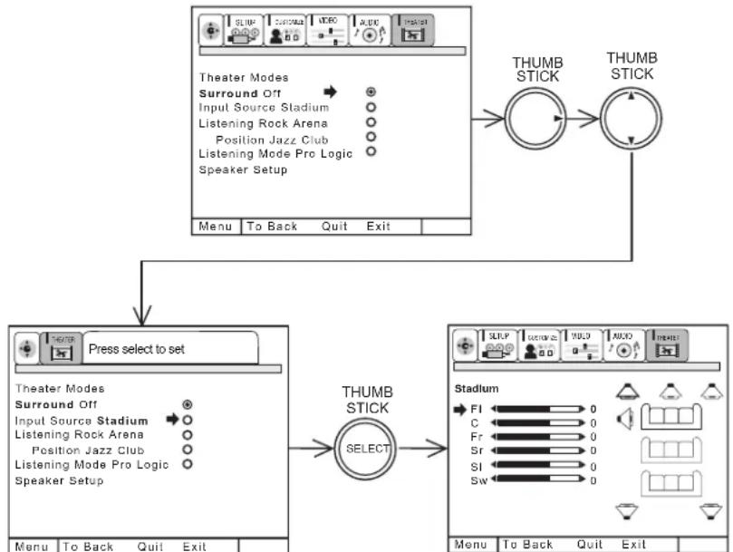
flowchart
graph TD
    A["Theater Modes"] --> B["Surround Off"]
    B --> C["Input Source Stadium"]
    C --> D["Listening Rock Arena"]
    D --> E["Position Jazz Club"]
    E --> F["Listening Mode Pro Logic"]
    F --> G["Speaker Setup"]
    G --> H["Menu To Back Quit Exit"]
    I["THUMB STICK"] --> J["THUMB STICK"]
    K["Press select to set"] --> L["Thunder Mode"]
    L --> M["Select"]
    N["THUMB STICK"] --> O["THunder Mode"]
    P["THUMB STICK"] --> Q["THunder Mode"]
    R["THUMB STICK"] --> S["THunder Mode"]
    T["THUMB STICK"] --> U["THunder Mode"]
    V["THUMB STICK"] --> W["THunder Mode"]
    X["THUMB STICK"] --> Y["THunder Mode"]
    Z["THUMB STICK"] --> AA["THunder Mode"]
    AB["THUMB STICK"] --> AC["THunder Mode"]
    AD["THUMB STICK"] --> AE["THunder Mode"]
    AF["THUMB STICK"] --> AG["THunder Mode"]
    AH["THUMB STICK"] --> AI["THunder Mode"]
    AJ["THUMB STICK"] --> AK["THunder Mode"]
    AL["THUMB STICK"] --> AM["THunder Mode"]
    AN["THUMB STICK"] --> AO["THunder Mode"]
    AP["THUMB STICK"] --> AQ["THunder Mode"]
    AR["THUMB STICK"] --> AS["THunder Mode"]
    AT["THUMB STICK"] --> AU["THunder Mode"]
    AV["THUMB STICK"] --> AW["THunder Mode"]
    AX["THUMB STICK"] --> AY["THunder Mode"]
    AZ["THUMB STICK"] --> BA["THunder Mode"]
    BB["THUMB STICK"] --> BC["THunder Mode"]
    BD["THUMB STICK"] --> BE["THunder Mode"]
    BF["THUMB STICK"] --> BG["THunder Mode"]
    BH["THUMB STICK"] --> BI["THunder Mode"]
    BJ["THUMB STICK"] --> BK["THunder Mode"]
    BL["THUMB STICK"] --> BM["THunder Mode"]
    BN["THUMB STICK"] --> BO["THunder Mode"]
    BP["THUMB STICK"] --> BQ["THunder Mode"]
    BR["THUMB STICK"] --> BS["THunder Mode"]
    BT["THUMB STICK"] --> BU["THunder Mode"]
    BV["THUMB STICK"] --> BW["THunder Mode"]
    BX["THUMB STICK"] --> BY["THunder Mode"]
    BZ["THEATERS MODE"] --> CA["THEATERS MODE"]
    CB["THEATERS MODE"] --> CD["THEATERS MODE"]
    CE["THEATERS MODE"] --> CF["THEATERS MODE"]
    CG["THEATERS MODE"] --> DH["THEATERS MODE"]
    DI["THEATERS MODE"] --> DJ["THEATERS MODE"]
    DK["THEATERS MODE"] --> DL["THEATERS MODE"]
    DM["THEATERS MODE"] --> DN["THEATERS MODE"]
    DO["THEATERS MODE"] --> DA["THEATERS MODE"]
    DB["THEATERS MODE"] --> DC["THEATERS MODE"]
    DD["THEATERS MODE"] --> DE["THEATERS MODE"]
    EF["THEATERS MODE"] --> EG["THEATERS MODE"]
    EH["THEATERS MODE"] --> EI["THEATERS MODE"]
    AJ["THEATERS MODE"] --> BK["THEATERS MODE"]
    BLT["THEATERS MODE"] --> BU["THEATERS MODE"]
    BVW["THEATERS MODE"] --> BXT["THEATERS MODE"]
    BXT["THEATERS MODE"] --> BYT["THEATERS MODE"]
    BXU["THEATERS MODE"] --> BYU["THEATERS MODE"]
To enter the SURROUND MODE, use THUMB STICK ▲ or ▼ to highlight then press down on THUMB STICK to select SURROUND MODE of your choice.
Now press THUMB STICK ▲ or ▼ to select speaker to be adjusted.
Use THUMB STICK ◀ or ▶ to adjust the volume of the highlighted speakers. MAIN volume also controls AUDIO TO HI-FI output level. Adjust MAIN volume first.
Each SURROUND setting has separate FL (Front Left), C (Center), FR (Front Right), SR (Surround Right), SL (Surround Left), and SW (Sub Woofer) volume controls, except OFF, which has only balance and SW (Sub Woofer) controls.
All speaker volumes will increase or decrease when the main VOLUME is set.
The maximum volume allowed for the CENTER, REAR, and SUB WOOFER will depend on how loud the MAIN volume is set.
SURROUND OFF
Use this for normal stereo/mono broadcasts.
STADIUM SURROUND
Select this mode to simulate being at a sporting event.
ROCK ARENA SURROUND
Select this mode to simulate being at a medium sized Rock Arena.
JAZZ CLUB SURROUND
Select this mode to simulate being at a small Jazz Club.
PRO LOGIC SURROUND
Select this mode when viewing a program which is DOLBY PRO LOGIC encoded. (see page 66 for more information)
DOLBY DIGITAL SURROUND
Select this mode when viewing a program which is DOLBY DIGITAL encoded and you have a digital (optical or coaxial) input. (see page 67 for more information)
NOTES: 1. This TV can not decode or process Digital DTS Surround signals.
- If you can not adjust SR, SL, or SW, make sure they are turned on in the THEATER - SPEAKER SETUP menu. (see page 70)
Dolby Pro Logic provides four separate sound channels: front left, center, front right, and surround. For properly encoded programs marked ☐ DOLEY SURROUND PRO·LOGIC the center sound channel contains the dialogue for the program viewed. The left and right channels produce sound effects that will match the action on the TV screen. For example, Dolby Pro Logic will enhance the effect of a car viewed driving from the left side of the TV screen to the right side. The surround channel (speakers) are placed behind the viewing area to add additional spatial sound effects.
To fully benefit from Dolby Pro Logic Surround, it is recommended that the surround speaker system be complete, as shown on page 17.
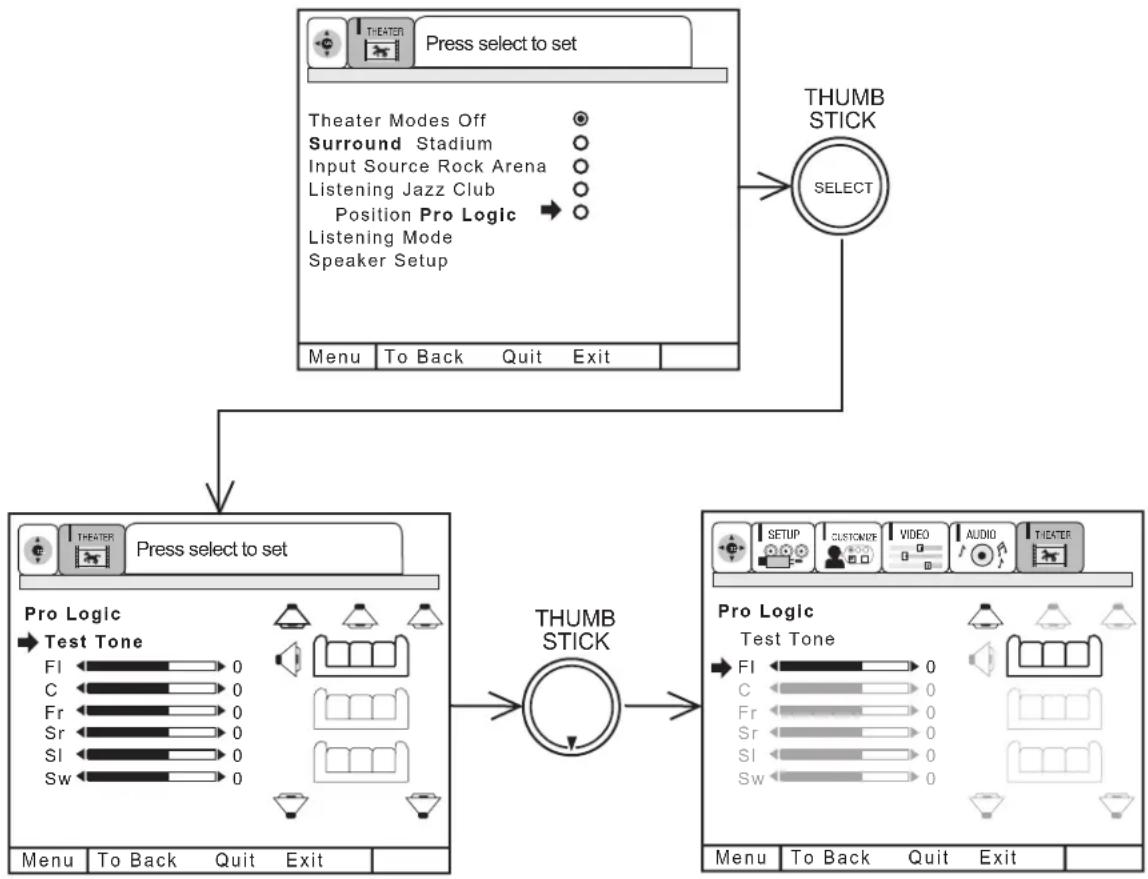
flowchart
graph TD
    A["Press select to set"] --> B["Theater Modes Off"]
    A --> C["Surround Stadium"]
    A --> D["Input Source Rock Arena"]
    A --> E["Listening Jazz Club"]
    A --> F["Position Pro Logic"]
    A --> G["Listening Mode"]
    A --> H["Speaker Setup"]
    A --> I["Menu"]
    A --> J["To Back"]
    A --> K["Quit"]
    A --> L["Exit"]
    M["THUMB STICK"] --> N["SELECT"]
    O["Press select to set"] --> P["Pro Logic"]
    P --> Q["Test Tone"]
    Q --> R["FI 0"]
    Q --> S["C 0"]
    Q --> T["Fr 0"]
    Q --> U["Sr 0"]
    Q --> V["SI 0"]
    Q --> W["Sw 0"]
    X["THUMB STICK"] --> Y["Pro Logic"]
    Y --> Z["Test Tone"]
    Z --> AA["FI 0"]
    Z --> AB["C 0"]
    Z --> AC["Fr 0"]
    Z --> AD["Sr 0"]
    Z --> AE["SI 0"]
    Z --> AF["Sw 0"]
    Y --> AG["Menu"]
    Y --> AH["To Back"]
    Y --> AI["Quit"]
    Y --> AJ["Exit"]
Press THUMB STICK ◀ or ▶ to change volume level of each speaker independently.
Press SELECT on THUMB STICK when TEST TONE is highlighted and TV will automatically cycle through all speakers. Simply wait until the speaker you wish to adjust is highlighted (static noise will be heard from this speaker), then use THUMB STICK ◀ or ▶ to adjust VOLUME. Using TEST TONE, you can quickly and easily set each speaker volume to a desired level.
Press ▼ on THUMB STICK when TEST TONE is highlighted to manually cycle through all speakers.
When main VOLUME is changed, all speaker volumes will change according to the percentages you set in this menu.
Set TV balance by adjusting FL (Front Left) and FR (Front Right) volume control.
NOTE: Center channel audio will always be heard from the TV's center speaker. If THEATER-SPEAKER SETUP-FRONT L/R is set to EXTERNAL W/AMP, center channel audio will still be heard from the TV's center speaker. Only the front Left and Right internal TV speakers can be turned off.
Dolby Digital provides six independent sound channels: front left, center, front right, surround left, surround right, and sub woofer. Select this feature when viewing properly encoded programs marked ☐☐☐ DolBY DIGITAL.
To fully benefit from Dolby Digital Surround, it is recommended that the surround speaker system be complete, as shown on page 17.
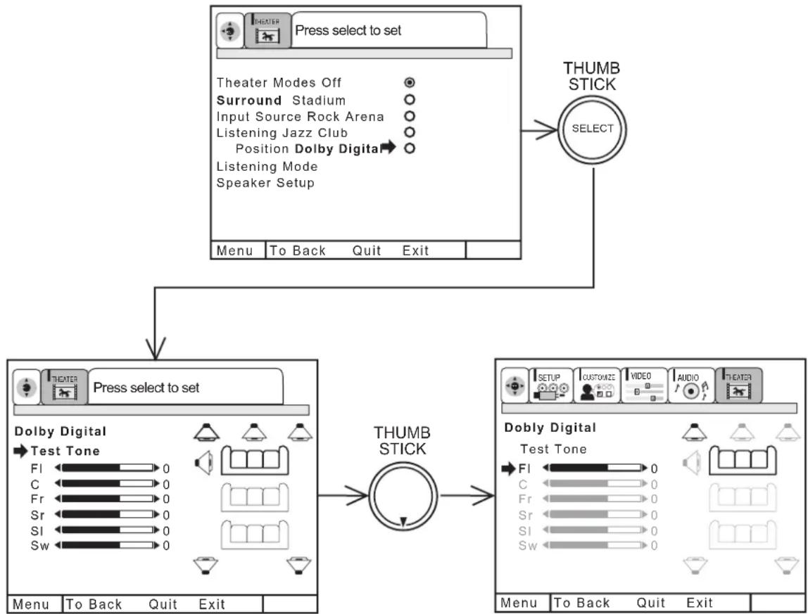
flowchart
graph TD
    A["Press select to set"] --> B["THUMB STICK SELECT"]
    B --> C["Dolby Digital Test Tone"]
    C --> D["THUMB STICK"]
    D --> E["Doby Digital Test Tone"]
    E --> F["THUMB STICK SELECT"]
    style A fill:#f9f,stroke:#333
    style B fill:#ccf,stroke:#333
    style C fill:#cfc,stroke:#333
    style D fill:#fcc,stroke:#333
    style E fill:#cff,stroke:#333
Press THUMB STICK ◀ or ▶ to change volume level of each speaker independently.
Press SELECT on THUMB STICK when TEST TONE is highlighted and TV will automatically cycle through all speakers. Simply wait until the speaker you wish to adjust is highlighted (static noise will be heard from this speaker), then use THUMB STICK ◀ or ▶ to adjust VOLUME. Using TEST TONE, you can quickly and easily set each speaker volume to a desired level.
Press ▼ on THUMB STICK when TEST TONE is highlighted to manually cycle through all speakers.
When main VOLUME is changed, all speaker volumes will change according to the percentages you set in this menu.
Set TV balance by adjusting FL (Front Left) and FR (Front Right) volume control.
NOTE: Center channel audio will always be heard from the TV's center speaker. If THEATER-SPEAKER SETUP-FRONT L/R is set to EXTERNAL W/AMP, center channel audio will still be heard from the TV's center speaker. Only the front Left and Right internal TV speakers can be turned off.
Set audio input to Digital or Analog. This fueature is used only when viewing VIDEO:4 or VIDEO:5 inputs, since only these inputs can accept DIGITAL audio input.
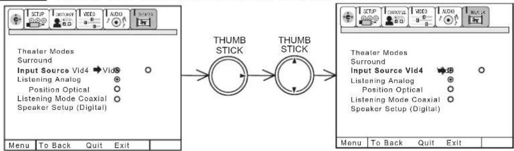
flowchart
graph LR
    A["Thealer Modes"] --> B["Input Source Vid4"]
    B --> C["Listening Analog"]
    C --> D["Position Optical"]
    D --> E["Listening Mode Coaxial"]
    E --> F["Speaker Setup (Digital)"]

    G["THUMB STICK"] --> H["THUMB STICK"]

    I["Theater Modes"] --> J["Input Source Vid4"]
    J --> K["Listening Analog"]
    K --> L["Position Optical"]
    L --> M["Listening Mode Coaxial"]
    M --> N["Speaker Setup (Digital)"]

    O["Menu"] --> P["To Back"]
    P --> Q["Quit"]
    Q --> R["Exit"]
Use THUMB STICK ▲ or ▼ to select DIGITAL or ANALOG.
Press EXIT to quit menu or THUMB STICK ◀ to return to previous menu.
NOTE: 1. This feature selects between DIGITAL (Optical and Coaxial) Inputs on rear panel and ANALOG (Audio Left/Right) Inputs on rear panel.
- DIGITAL audio can only be used for VIDEO:4 or VIDEO:5 inputs. ANT A, ANT B, and VIDEO:1,2 and 3 inputs can accept only ANALOG audio input.
- You cannot select COAXIAL for both VIDEO:4 and VIDEO:5 inputs. You also cannot select OPTICAL for both VIDEO:4 and VIDEO:5 inputs. You may only have 1 type of audio input for each rear panel input.
LISTENTING POSITION
Set for optimum audio performance based on your listening position.
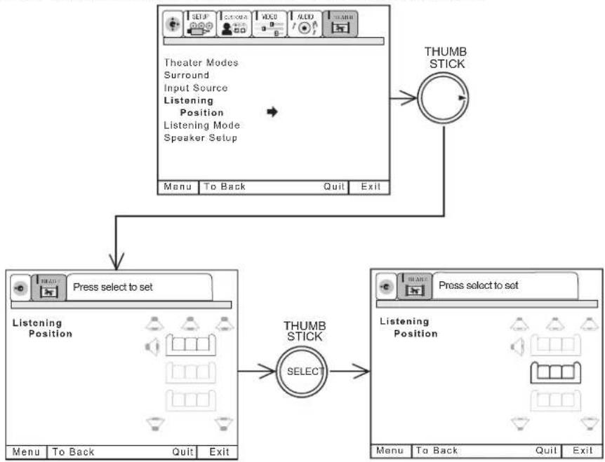
flowchart
graph TD
    A["Theater Modes\nSurround\nInput Source\nListening\nPosition\nListening Mode\nSpeaker Setup"] --> B["Menu\nTo Back\nQuit\nExit"]
    B --> C["Press select to set\nListening Position"]
    C --> D["THUMB STICK\nSELECT"]
    D --> E["Press select to set\nListening Position"]
    E --> F["Menu\nTo Back\nQuit\nExit"]
    F --> G["THUMB STICK"]
Press down on THUMB STICK to select Front, Center, or Rear LISTENING POSITION that matches your setup.
Press EXIT to quit menu or THUMB STICK ◀ to return to previous menu.
NOTES: 1. This feature adjusts audio delay to surround speakers to make audio performance optimum, based on your specific setup.
2. This feature is only accessible when SURROUND-PRO LOGIC and SURROUND-DOLBY DIGITAL modes are selected.
Choose between pre-set audio modes Standard, Night, or Maximum. Take advantage of these features to reduce or increase sound effects.
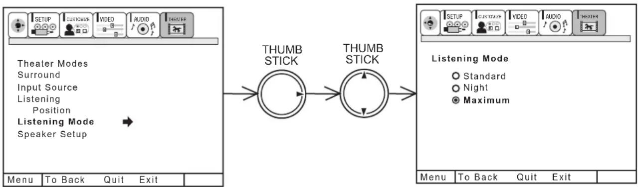
flowchart
graph LR
    A["Theater Modes"] --> B["Speaker Setup"]
    C["THUMB STICK"] --> D["THUMB STICK"]
    E["LISTENING MODE"] --> F["Menu"]
    G["To Back"] --> H["Quit Exit"]
    I["To Back"] --> J["Quit Exit"]
    K["STICK"] --> L["THUMB STICK"]
    M["STICK"] --> N["THUMB STICK"]
    O["STICK"] --> P["THUMB STICK"]
    Q["STICK"] --> R["THUMB STICK"]
    S["STICK"] --> T["THUMB STICK"]
    U["STICK"] --> V["THUMB STICK"]
    W["STICK"] --> X["THUMB STICK"]
Use THUMB STICK ▲ or ▼ to select STANDARD, NIGHT, MAXIMUM.
Press EXIT to quit menu or THUMB STICK ◀ to return to previous menu.
When STANDARD is selected:
It is the normal listening mode. It does not make full use of your televisions dynamic range, but is a good compromise for all day viewing/listening.
When NIGHT is selected:
This mode allows the audio to be reproduced in such a way that the impact of sound track extremes (such as explosions) are reduced while quiet passages are “boosted”, allowing all the audio information to be heard at a low volume level. As it’s name suggests, this mode is intended for night time viewing.
When MAXIMUM is selected:
This mode makes the best use of the televisions dynamic range. It will enhance the sound effects such as explosions or screams.
NOTES: 1. This feature is only accessible when SURROUND-DOLBY DIGITAL mode is selected and INPUT SOURCE-DIGITAL (Optical or Coaxial) is chosen.
2. You must be in VIDEO:4 or VIDEO:5 to access this feature, since these are the only inputs which accept DOLBY DIGITAL inputs.
Press THUMB STICK ▲ or ▼ to highlight feature.
Press down on THUMB STICK to select INTERNAL or EXTERNAL W/AMP.
Use THUMB STICK ▶ to change SURROUND or SUB WOOFER feature to your desired setting.
Press EXIT to quit menu or THUMB STICK ◀ to return to previous menu.
Select FRONT L/R - INTERNAL if you wish to use the TV internal Left and Right speakers.
Select FRONT L/R- EXTERNAL W/AMP if you wish to turn off the TV internal Left and Right speakers and use speakers connected to an external amplifier. This will provide better audio separation.
Select SURROUND - YES if you are using the TV speaker terminals (on rear panel) to power your surround speakers.
Select SURROUND - NO if you are not using the TV speaker terminals for your surround speakers or want to turn surround speakers OFF.
Select SUB WOOFER - YES if you have a sub woofer connected to the rear panel Sub Woofer jack. If you are not using this rear panel Sub Woofer jack or wish to turn OFF your SUB WOOFER, select SUB WOOFER - NO.
NOTES: 1. Surround speakers and Sub Woofer volume will increase and decrease when main volume is adjusted. Refer to THEATER-SURROUND menu on page 65 for instructions on how to set up your speakers.
2. If SURROUND-NO, SUB WOOFER-NO are selected, when THEATER-SURROUND is chosen you will not be able to adjust volume level of SL, SR, or SW. This is because these speakers are turned OFF by selecting SURROUND-NO and SUB WOOFER-NO.
DO
Dust the screen and cabinet with a soft cloth.
Clean the screen with a soft cloth moistened in warm water and dry with a soft cloth. A mild soap may be used if the screen is extremely dirty.
Place your television away from extreme heat, humidity, and extremely dusty places.
Remove the plug from the wall outlet if your television will not be used for a long period of time, for instances, when you go on vacation.
DO NOT
Do not clean your screen or cabinet with strong cleaners, polishes or a chemically treated cloth.
Do not place rubber or vinyl products or cellophane tape on your television.
Do not touch the screen too often.
Do not subject the remote control to shocks such as dropping it on the floor, etc. Physical damage to the precision parts may result.
Avoid placing the remote control in a high humidity place or getting it wet. Do not leave it on or near a heater. Excessive heat or moisture may cause the unit to cease operation.
When the batteries run down, remote control operation will become erratic or possibly stop altogether. Replace the old batteries with two new "AA" size batteries.
Exposure of the viewing screen to prolonged direct sunlight or heat may cause the screen to permanently warp, resulting in a distorted picture.
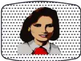 | • IGNITION NOISE:Black spots or horizontal streaks may appear, picture may flutter or drift.Usually caused by interference from automobile ignition systems, neon lamps, electrical drills, and other electrical appliances. |
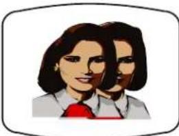 | • GHOSTS:Ghosts are caused by the television signal following two paths. One is the direct path and the other is reflected from tall buildings, hills or some other objects. Changing the direction or position of the antenna may improve reception. Ghosting may also be caused by defects in the antenna system such as unshielded leads or connecting several sets to the same antenna without using multiple antenna couplers. |
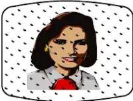 | • SNOW:If your receiver is located in the fringe area of a television station where the signal is weak, your picture may be marred by the appearance of small dots. When the signal is extremely weak, it may be necessary to install a special antenna to improve the picture. |
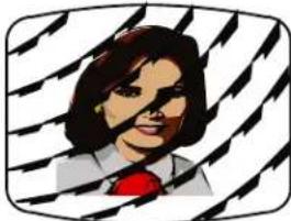 | • RADIO FREQUENCY INTERFERENCE:The interference produces moving ripples or diagonal streaks, and in some cases, causes loss of contrast in the picture. |
NOTE: The TV set can generate sound distortion in external devices such as a radio. Please separate radio equipment from the TV set to a considerable distance.
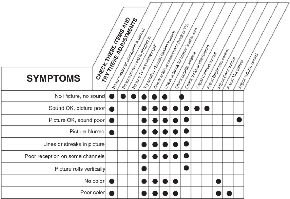
HITACHI Projection Television incorporates advanced power surge protection technology designed to protect against component or circuit damage due to external or internal voltage power surges.
IF YOUR TELEVISION SHOULD APPEAR TO HAVE A LOSS OF POWER, PLEASE FOLLOW THIS PROCEDURE:
- Press the power switch (ON/OFF switch) once.
- If there is still no power, wait 30 seconds and press the power switch again.
- If there is still no power, unplug the power cord from the wall. Wait 30 seconds and plug the power cord back in. Press the power switch again.
This protective technology should provide for years of lasting entertainment from your HITACHI Projection Television.
Features:
• Superfine Picture Quality
1200 Line Horizontal Resolution
• PERFECT PICTURE System
- Remote (Controls many VCR brands, cable boxes, satellite boxes, and other audio equipment.)
• High Definition On-Screen Display (UltraTEC BIT-MAP)
• ON SCREEN PLUG and PLAY guide
• Full Set of Input Jacks, including S-VIDEO
• COMPONENT VIDEO: Y-P _B /PR
• V elocity Modulation
- Closed Caption Decoder
• 2-Tuner Picture in Picture (Single, Split and Surf-3)
- Magic Focus (Auto Digital Convergence)
• Dual Antenna Inputs
• V ideo Input Sensor
• 3 Dimensional Y/C Comb Filter
• Full 1080i HDTV capable when used with a Set-Top Box.
• DBE T technology.
• SRS T e c h n o l o g y
*SRS and the (●) symbol are registered trademarks of SRS Labs, Inc. in the United States and selected foreign countries. SRS technology is incorporated under license from SRS Labs, Inc.
*Licensed by BBE Sound, Inc. under USP4638258 and 4482866. BBE and BBE symbol are registered trademarks of BBE Sound, Inc. Manufactured under license from BBE Sound, Inc.
• Dolby Digital, Dolby Pro Logic, Stadium, Rock Arena, Jazz Club Surround Sound
*Manufactured under license from Dolby Laboratories. "Dolby", "Pro Logic" and the double-D symbol are trademarks of Dolby Laboratories. Confidential Unpublished Works. ©1992-1997 Dolby Laboratories, Inc. All rights reserved.
Inputs:
• Power Input .....AC 120V, 60Hz
- Stand-by Power .....2.7W
• Power Consumption
- Refer to rear panel at the back of the T.V.
- Antenna input impedance .....75 Ohm
- Channel coverage .....181ch.
VHF-Band 2\~13
UHF-Band 14 \~ 69
CATV Mid Band ....A-5 \~ A-1 ....A-I
Super Band . . . . . . . . . . . . . . . . . . . . . . . . . . . . . . . . . . . . . . . . . . . . . . . . . . . . J-W
Hyper Band . . . . . . . . . . . . . . . . . . . . . . . . . . . . . . . . . . . . . . . . . . . . . . W+1 - W+28
Ultra Band . . . . . . . . . . . . . . . . . . . . . . . . . . . . . . . . . . . . . . . . . . . . . . . . . . . . . . . . . . . W+29 - W+84
• V ideo ....1.0Vp-p, 75 Ohm
• S-Video
Luminance (Y) .....1.0Vp-p, 75 Ohm
Chrominance (C) .....0.286Vp-p, 75 Ohm
- Component Video
Luminance (Y) .....1.0Vp-p, 75 Ohm
Chrominance (P B /P R ) .....0.7Vp-p, 75 Ohm
• Audio input Impedence .....47k Ohm
• A verage input level .....470mVrms
Outputs:
• V ideo ....1.0Vp-p. 75 Ohm
• Audio ....470mVrms, 1k Ohm
Dimensions:
| 43UWX10B | 53UWX10BA/53SWX10B/53SWX12B | 61UWX10BA/61SWX10B/61SWX12B | |
| Height (in.) | 39 | 54 1/32 | 60 7/32 |
| Width (in.) | 41 7/32 | 50 17/32 | 57 1/2 |
| Depth (in.) | 20 5/8 | 29 | 29 19/32 |
| Weight (lbs.) | 153 | 245 | 245 |
NOTE: Due to improvements, specifications in this operating guide are subject to change without notice.
HITACHI
To locate an authorized HITACHI service facility in the continental U.S.A. and Canada,
DIAL TOLL FREE
7 days a week, 24 hours a day
800 HITACHI
(1-800-448-2244)
Hitachi America, LTD. Home Electronics Division
Hitachi has made every effort to assure you hours of trouble free operation from your unit. However, should you require service, a network of Hitachi Authorized Service Facilities has been established in all 50 states and Puerto Rico. Each facility will provide you with convenient and expedient assistance. Our service hotline operator will direct you to the Hitachi Authorized Service Facility nearest you. Just present proof of purchase and/or delivery receipts to the Hitachi Authorized Service Facility, and service will be rendered in accordance with the terms of the limited warranty as stated on your warranty card or operating guide.
Should you have any questions regarding warranty, service, operation, or technical assistance, please contact:
Hitachi America, LTD.
Home Electronics Division
1855 Dornoch Court
San Diego, CA 92154
In Canada, please contact: 1-800-HITACHI (1-800-448-2244)
HITACHI (HSC) Canada Inc.
6740 Campobello Road
Mississauga, Ont. L5N 2L8
HITACHI
- WARNING
- WARNING:
- MODIFICATIONS:
- POWER SOURCE
- IMPORTANT SAFETY INSTRUCTIONS
- CAUTION:
- FOR YOUR PERSONAL SAFETY
- PROTECTION AND LOCATION OF YOUR TELEVISION
- IF THE TELEVISION DOES NOT OPERATE PROPERLY
- FOR SERVICING AND MODIFICATION
- PICTURE CAUTIONS
- Picture Burn Prevention
- Public Viewing of Copyrighted Material
- REMOTE CONTROL BATTERY INSTALLATION AND REPLACEMENT
- ANTENNA
- LOCATION
- VIEWING
- 300-Ohm Twin Lead Connector
- Phono Connector
- "F" Type 75-Ohm Coaxial Antenna Connector
- S-VIDEO (Super Video) Connector
- ANTENNA CONNECTIONS TO REAR JACK PANEL
- VHF (75-Ohm) antenna/CATV (Cable TV)
- VHF (300-Ohm) antenna/UHF antenna
- When both VHF and UHF antennas are connected
- ① MENU/SELECT button
- ② INPUT/EXIT button
- ③ CHANNEL selector
- ④ VOLUME level
- ⑤ POWER button
- ⑥ POWER light
- ⑦ PERFECT PICTURE sensor
- ⑧ REMOTE CONTROL sensor
- ⑨ MAGIC FOCUS
- ⑩ FRONT INPUT JACKS (for VIDEO: 3)
- ① Antenna Input/Output
- ② Audio/Video Inputs 1, 2, 4 and 5
- ③ MONITOR OUT
- ④ AUDIO TO HI-FI Output
- ⑤ S-VIDEO Inputs 1 and 2
- ⑥ Component: Y-P _B P _R Inputs
- Items ⑦ \~ ⑩ are for 53/61SWX10B and 53/61SWX12B only.
- ⑦ REAR SPEAKER Output Terminals
- ⑧ Optical Input
- ⑨ Coaxial Input
- ⑩ SUB WOOFER Output
- NOTE:
- TYPICAL FULL-FEATURE SETUP
- (53/61SWX10B AND 53/61SWX12B MODELS)
- CONNECT AFTER TURNING THE POWER TO THE TV OFF.
- (Rear speaker connection applies to SWX model only)
- TIPS ON REAR PANEL CONNECTIONS
- CONNECTING EXTERNAL AUDIO AMPLIFIER
- REAR PANEL OF TELEVISION
- Before Operating External Video Source
- CONNECTING A MONAURAL AUDIO SOURCE TO INPUT1\~INPUT5
- CONNECTING A STEREO SOURCE TO INPUT1\~INPUT5
- CONNECTING AN S-VIDEO SOURCE TO INPUT 1, 2 AND 3
- NOTES:
- CONNECTING A COMPONENT SOURCE TO VIDEO 4 OR 5: Y-PBPR.
- NOTE: 1. You may use standard video signal for INPUT:4 and 5.
- ②,③ LIGHT BUTTON
- HOW TO USE THE GENIUS REMOTE TO CONTROL YOUR TV
- ⑦ AV1, AV2, AV3, or CD, TAPE, AMP buttons
- ⑧ CHANNEL selector buttons
- ⑨ SLEEP button
- ⑪ ANTENNA button
- ⑫ C.C. button
- ⑬ HELP button
- ⑭ ASPECT button
- ⑮ PIX or MODE button
- ⑯ MENU button
- ⑰ EXIT button
- ⑱ THUMB STICK/SELECT button
- ⑲ VOLUME, MUTE button
- ⑳ STATUS button
- ②1 PICTURE-IN-PICTURE buttons
- ② PIP CH button
- ②3 VID1 \~ VID5
- ① PIP button
- SINGLE MODE PIP
- PICTURE-IN-PICTURE CONT.
- SPLIT MODE PIP
- SURF MODE PIP
- ② SWAP button
- ③ PIP MODE button
- ④ FREEZE button (With PIP ON)
- ⑤ FREEZE button (With PIP OFF)
- SINGLE FREEZE
- SPLIT FREEZE(with PIP off)
- STROBE FREEZE(with PIP OFF)
- Operating the precoded function for your VCR.
- Operating the precoded function for your Audio/Video component.
- SET MENU LANGUAGE
- PLUG & PLAY
- SET ANTENNA/CABLE
- SET CHANNEL MEMORY
- EDIT CHANNEL MEMORY
- VIEW CHANNEL LIST
- SET THE CLOCK
- MAGIC FOCUS
- PICTURE FORMATS
- ASPECT STYLE
- POSITION
- COMPONENT COLOR TYPE
- VIDEO DISPLAY
- NAME THE INPUTS
- SET FAVORITE CHANNELS
- FAVORITE CHANNELS (OPERATION)
- SET PARENTAL LOCKS
- SET PROGRAM TIMER
- VIDEO INPUT SENSOR
- CLOSED CAPTION
- MENU BACKGROUND
- CONTRAST
- BRIGHTNESS
- COLOR
- TINT
- SHARPNESS
- RESET
- ADVANCED SETTINGS
- PERFECT PICTURE
- AUTO COLOR
- NOISE REDUCTION
- VELOCITY MODULATION
- BASS
- TREBLE
- BALANCE
- MTS MODE
- INTERNAL SPEAKERS
- AUTO NOISE CANCEL
- LOUDNESS
- PERFECT VOLUME
- DYNAMIC BASS
- THEATER MODES
- NOTE: MOVIE MODE 3:2 PULLDOWN DETECTION SPECIAL FEATURE
- Surround
- SURROUND OFF
- SRS
- by SRS(●)\*
- BBE Technology
- STADIUM SURROUND
- ROCK ARENA SURROUND
- JAZZ CLUB SURROUND
- PRO LOGIC SURROUND
- DOLBY DIGITAL SURROUND
- LISTENTING POSITION
- DO
- DO NOT
- Features:
- Inputs:
- Outputs:
- HITACHI
- DIAL TOLL FREE
- HITACHI
- Hitachi America, LTD. Home Electronics Division
Brand : HITACHI
Model : 61SWX12B
Category : Television