Fast 1241 - Phone SAGEM - Free user manual and instructions
Find the device manual for free Fast 1241 SAGEM in PDF.

| Product Type | Corded Telephone |
| Brand | Sagem |
| Model | Fast 1241 |
| Dimensions (approx.) | 22 x 18 x 8 cm |
| Weight (approx.) | 450 g |
| Power Supply | Powered via telephone line (no batteries required) |
| Display | LCD screen with backlight |
| Caller ID | Yes, with call log memory |
| Handsfree Function | Yes, built-in speaker and microphone |
| Redial | Last number redial |
| Mute | Yes, mute button during call |
| Volume Control | Adjustable ringer and handset volume |
| Ringer Settings | Selectable ring melodies and volume levels |
| Wall Mountable | Yes, with bracket (included) |
| Cord Length (approx.) | 1.8 m handset cord, 2 m line cord |
| Material | ABS plastic |
| Color | Black or silver (depending on variant) |
| Maintenance | Clean with soft dry cloth; avoid liquids |
| Safety | Keep away from moisture and heat sources |
| Spare Parts / Repairability | Not applicable; device is not user-serviceable |
| General Information | Desk or wall installation; compatible with analog PSTN lines |
Frequently Asked Questions - Fast 1241 SAGEM
User questions about Fast 1241 SAGEM
0 question about this device. Answer the ones you know or ask your own.
Ask a new question about this device
Download the instructions for your Phone in PDF format for free! Find your manual Fast 1241 - SAGEM and take your electronic device back in hand. On this page are published all the documents necessary for the use of your device. Fast 1241 by SAGEM.
USER MANUAL Fast 1241 SAGEM
natural_image
Black SAGEM device casing with visible branding and control buttons (no readable text beyond branding)Reference Manual
288 110 393-01
Edition of October 2006
Sagem Communication assiduously monitors technical developments and is constantly seeking to improve its products in order to let its clients take full advantage of them. It therefore reserves the right to modify its documentation accordingly without notice.
All brands mentioned in this guide are registered by their respective owners:
• SAGEM F@st™ is a registered brand of Sagem Communication.
• SAGEM F@st™ is a registered brand of Sagem Communication.
- Windows ^TM and Internet Explorer ^TM are registered brands of Microsoft Corporation.
- Apple® and Mac®OS are registered brands of Apple Computer Incorporation.
The purpose of the present reference manual is to give users the functions for operating and managing the equipment. The only access level required (Administrator) is protected by a password and allows one to access these functions in read and write mode for all the user and network parameters (Standard values: Login: admin, password: admin).

Configuration of the router by HTTP is described in detail (cf. section 5).
For better legibility of the reference manual, the term "router" will be used throughout the document to designate SAGEM F@st™ 1201 and SAGEM F@st™ 1241 equipment. When description is addressed to a type of quite precise equipment, the name of this equipment will be mentioned.
By defect all the functions described on the SAGEM F@st ^TM 1201 are also available on the SAGEM F@st ^TM 1241.
Convention of symbols used in this manual

Warns you not to do an action, or commit a serious omission.

Gives you important information which you must take into account
How should the document be used?
The present reference manual is organised into sections and annexes. These sections and annexes cover the following subjects.
Section 1 Presentation of SAGEM F@st™ 1201 equipment
Section 2 Presentation of SAGEM F@st™ 1201 equipment
Section 3 Presentation of SAGEM F@st™ 1201 equipment
Section 4 Configuration of network parameters
Section 5 Configuration of the residential platform by HTTP
Section 6 Description of Internet access service
Section 7 Updating the application
Annex A Troubleshooting
Annex B CE compliance declaration
Annex C Environment
Annex D Technical Characteristics
Annex E Default configuration
Annex F Glossary
Annex G Connection technology
Contents
Pages
Contents 0-3 to 0-6
1. Introduction 1-1
1.1 Presentation 1-2
1.2 Composition of router pack 1-4
1.3 Minimum prerequisite 1-5
2. Description and connection of router 2-1
2.1 Description 2-2
2.1.1 "Connectors" side view 2-3
2.1.2 "LEDs" view 2-4
2.2 Connecting the ports of your router 2-5
2.2.1 Connecting to a power socket 2-6
2.2.2 Connection of the ADSL cable to the router 2-7
2.2.3 Connecting to your computer 2-8
2.2.3.1 Connection of the USB interface of your router to your computer 2-8
2.2.3.2 Connecting the Ethernet interface of your router to your computer 2-9
2.3 Installation instructions 2-10
3. Installing and configuring the router 3-1
3.1 Installing and configuring your Router with the network card of your computer (Ethernet) 3-4
3.2 Installing and configuring your Router in the USB port of your computer 3-8
3.3 Installing and configuring an additional computer 3-12
4. Configuration of network parameters 4-1
5. Information / Configuration 5-1
5.1 Accessing the welcome screen 5-2
5.2 Recommendations 5-4
5.3 ADSL connection status 5-5
5.4 Display frame 5-5
5.5 Status 5-6
5.5.1 Summary 5-6
5.5.2 Diagnostics 5-7
5.6 Internet Connection 5-9
5.7 NAT 5-10
5.7.1 Port forwarding 5-10
5.7.2 DMZ Host 5-15
5.8 Advanced Setup 5-16
5.8.1 WAN 5-16
5.8.2 LAN 5-38
5.8.3 Security 5-40
5.8.3.1 Outgoing 5-40
5.8.3.2 Incoming 5-42
5.8.4 Routing 5-45
5.8.4.1 Default Gateway
5.8.4.2 Static Route
5.8.5 DNS
5.8.6 DSL 5-49
5.9 Advanced Status
5.9.1 WAN 5-52
5.9.2 Statistics
5.9.2.1 LAN
5.9.2.2 WAN
5.9.2.3 ATM
5.9.2.4 ADSL
5.9.3 Route
5.9.4 ARP
5.9.5 DHCP
5-45
5-46
5-48
5-52
5-53
5-53
5-54
5-55
5-56
5-57
5-58
5-59
5.10 Management
5.10.1 Settings 5-60
5.10.1.1 Backup
5.10.1.2 Update
5.10.1.3 Restore Default
5.10.2 System Log
5.10.3 Access Control
5.10.3.1 Services
5.10.3.2 IP Address
5.10.3.3 Passwords
5.10.4 Update Software
5.10.5 Save/Reboot
5-60
5-61
5-63
5-64
5-65
5-70
5-70
5-71
5-73
5-74
5-75
6. Internet access service
6-1
6.1 Introduction
6-2
6.2 Connection for Internet access
6-3
7. Updating the application 7-1
A. Annex A - Troubleshooting A-1
A.1 Checking the attribution of an IP address A-2
A.1.1 In Windows A-2
A.1.2 On a Mac (for example MacOS X) A-2
A.2 Front Face LEDs A-3
A.3 Supervising your router A-4
A.4 "Diagnostics" tool A-5
A.5 Interpreting the LEDs A-7
A.5.1 The "ADSL" LED blinks slowly A-7
A.5.2 All LEDs are off A-7
A.6 Reinitialising your router A-8
A.7 Re-establishing the factory configuration A-8
A.8 Offline mode A-9
B. Annex B - Warnings for safety B-1
B.1 Warnings for safety B-2
B.1.1 Safety levels in relation to the case B-2
B.2 CE compliance declaration B-3
C. Annex C - Environment C-1
C.1 Directive E 2002/96/CE C-2
D. Annex D - Technical Characteristics D-1
D.1 Mechanics; Display D-2
D.2 Characteristics of the different interfaces D-3
D.3 Environmental characteristics D-4
D.4 Application and protocols D-5
E. Annex E - Default configuration E-1
E.1 Default username and password E-2
E.2 Default configuration for the local network(LAN) E-2
E.3 Default configuration for the remote network (WAN) E-2
F. Annex F - Glossary F-1
G. Annex G - Connector Technology G-1
G.1 Pinouts of the "LINE" connector G-2
G.2 Pinouts of the "PWR" connector G-2
G.3 Pinouts of the "ETH" connector G-3
G.4 Pinouts of the "USB" connector G-4
1. Introduction
| This section covers ➤ | presentation of the SAGEM F@stTM 1201/1241 equipment § 1.1 |
| ➢ composition of the packaging § 1.2 | |
| ➢ required hardware and software § 1.3 |
1.1 Presentation
The present reference manual is dedicated to the SAGEM F@st™ 1201 and SAGEM F@st™ 1241 product ranges. These products are routers which give users, via an ADSL/ADSL2/ ADSL2+ network, broadband Internet access from their computer or their games console by various Ethernet (10 or 100 BASE-T) or USB interfaces.

SAGEM F@st™ 1201 and SAGEM F@st™ 1241 products adapt the ADSL function respectively for POTS (UIT G.992.1/3/5 - Annex A) and for ISDN (UIT G.992.1/3/5 - Annex B).
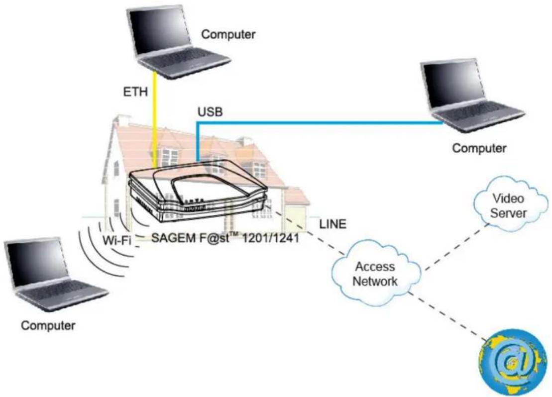
flowchart
graph TD
    A["Computer"] -->|Wi-Fi| B["SAGEM F@st™ 1201/1241"]
    C["Computer"] -->|USB| B
    B -->|LINE| D["Access Network"]
    D --> E["Video Server"]
    E -.-> D
    style A fill:#f9f,stroke:#333
    style C fill:#f9f,stroke:#333
    style B fill:#ccf,stroke:#333
    style D fill:#cfc,stroke:#333
    style E fill:#fcc,stroke:#333
Figure 1.1 - Supervising your router
Its principal characteristics and functions are as follows:
High-performance secure Bridge/Router with ADSL/ADSL2/ADSL2+ interface,
User access:
• 1 10/100BT Ethernet port,
• 1 USB1.1 Slave port,
DHCP Client/Server/Relay,
DNS Server/Relay,
FTP Client/Server,
TFTP Client/Server,
HTTP Client/Server,
NAT/PAT router - FTP Compatibility, IRC, Net2Phone, Netbios, DNS, Netmeeting, SIP, VPN passthrough (IPSec, IKE, PPTP, L2TP), CUSeeMe, RealAudio, Microsoft IM and others,
Firewall,
Spanning tree,
▶ HTTP server for easy configuration,
➢ Manual update of the application version locally.
1.2 Composition of router pack
The router is supplied in a pack with the following contents:
➢ 1 SAGEM F@st™ 1201 or SAGEM F@st™ 1241,
➢ 1 mains adapter unit,
➢ 1 grey ADSL RJ11/RJ11 FDT line cord (length = 3 m),
➢ 1 yellow Ethernet RJ45/RJ45 linking cord (length = 1.75 m),
➢ 1 blue USB Type A male/Type B male cable (length = 1.5 m),
➢ 1 Quick Installation Guide,
➢ 1 Installation CD-ROM,
➢ microfilter(s) (option),
➢ 1 filter/splitter (option).
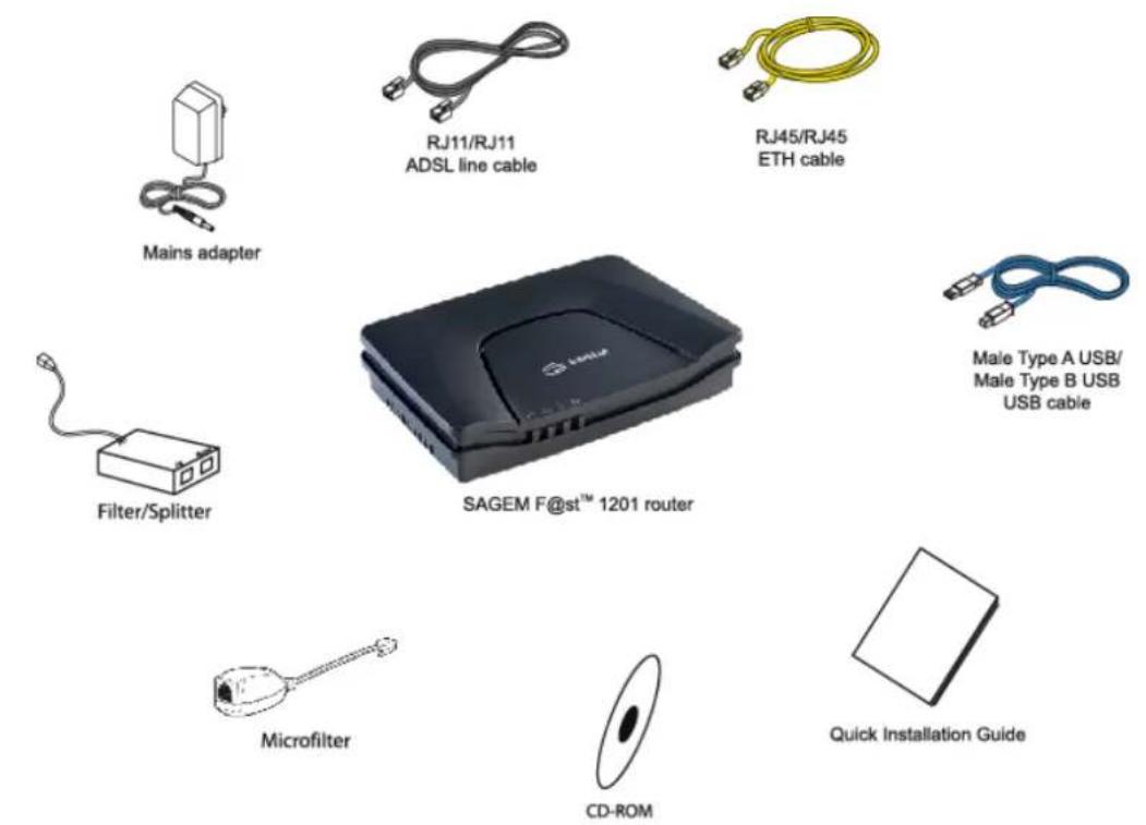
text_image
Mains adapter RJ11/RJ11 ADSL line cable RJ45/RJ45 ETH cable Filter/Splitter SAGEM F@st™ 1201 router Male Type A USB/ Male Type B USB USB cable Microfilter CD-ROM Quick Installation GuideThe CD ROM contains:
- the application for installing the USB interface.
- the present Reference Manual (SAGEM F@st™ 1201/1241) in PDF format file.
- the CE declaration of the chosen router.

Incomplete or damaged supply. If on its receipt the equipment is damaged or incomplete, contact the Supplier of your router.
1.3 Minimum prerequisite
Using a router requires at minimum:
▶ a computer equipped:
- a type A USB interface
or
- an Ethernet interface (10BASE-T or 10/100BASE-T),
➢ a WEB browser (Internet Explorer version 5 or higher recommended).
The minimum configuration of your computer must be:
for Windows: Pentium II, 400 MHz, RAM: 128 MB,
for MacOS: Power PC G3, 233 MHz, RAM: 128 MB,
➢ a monitor of minimum resolution: 1024 x 768.

Before installing the router, we advise you to uninstall any modem or other router (for example, an ADSL router).
1 - Introduction
2. Description and connection of router
| This section covers | the description of your router | § 2.1 |
| connecting the ports of your router § 2.2 | ||
| connecting to a power socket § 2.2.1 | ||
| connecting the line cable § 2.2.2 | ||
| connecting your computer § 2.2.3 | ||
| installation instructions § 2.3 |
2.1 Description
Figure 2.1 gives an overview of a router SAGEM F@st™ 1201 or SAGEM F@st™ 1241.

natural_image
Black SAGEM device casing with visible branding and buttons (no text beyond brand name)Figure 2.1 - Overview of case
This case consists principally of a lid and a base in which a printed circuit equipped with electronic components is located.
The front face has four display LEDs (cf.§ 2.1.2).
The base has the LEDs ideograms, SAGEM's mark and logo or the operator's marking as well.
Below the base a label is glued on which the product's identification code, the series number and a barcode are shown.
2.1.1 "Connectors" side view
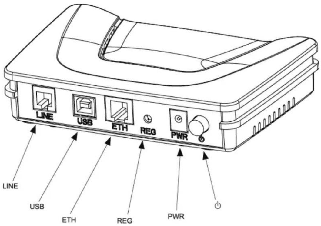
text_image
LINE USB ETH REG PWR LINE USB ETH REG PWR| Marking Meaning | |
| LINE | RJ11 connector - 6 pts. This grey connector is used for the connection to an ADSL line (WAN interface). |
| USB | Type B USB female connector. This blue connector is used for connection to a computer (USB interface). |
| ETH | RJ45 connector - 8 pts (10/100BASE-T Ethernet Interface). This yellow connector is is used for connection to a computer (10/100BASE-T ETH interface). |
| REG | This button allows the router to be reset to the factory configuration (see § A.7).Note: It is set back relative to the other elements to prevent an accidental loss of configuration. |
| On/Off switch. | |
| PWR | Miniature jack fixed connector.This connector enables the router to be supplied with direct current from a mains adapter unit. |
2.1.2 "LEDs" view
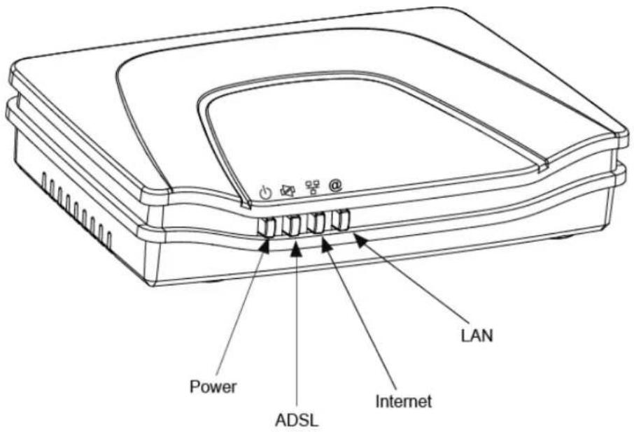
text_image
LAN Power ADSL InternetThe different LEDs of the figure below are described in the following table:
| Marking Abbreviation Meaning | ||
| PWR | Alarm LED (bicolour LED Green/Red):lits green if power is present,lits red in the case of failure detected at the time of starting.goes out if there is no power | |
| ADSL | Green ADSL LED:blinks slowly when the ADSL is not detected,blinks quickly when the ADSL line is being synchronised,stays lit when the ADSL line is detected. | |
| LAN | Green local network (LAN) LED:This LED indicates data traffic between the router and the different USB and Ethernet (ETH) interfaces.This LED is off if no interface (Ethernet or USB) is detected.This LED blinks when traffic is detected on one of the interfaces.This LED is lit when an Ethernet or USB interface is detected and if no traffic is detected. | |
| Internet | Internet connection LED (bicolour LED Green/Red):remains lit when the "PPP" connection is established or when the router is in "Bridge" mode,lits green when the "PPP" connection is established,lits red when the "PPP" connection is not established,blinks when traffic is detected on the WAN interface. | |
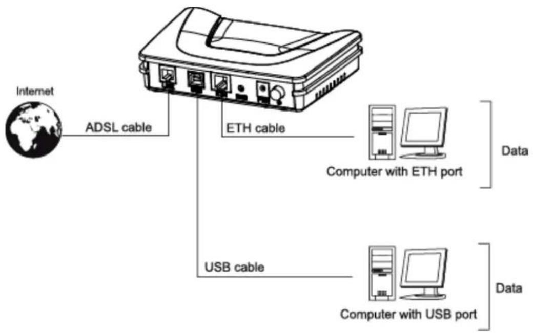
2.2 Connecting the ports of your router
text_image
Internet ADSL cable ETH cable Computer with ETH port USB cable Computer with USB port Data DataFigure 2.2 - Interconnection of ports of SAGEM F@st ^TM 1201/1241
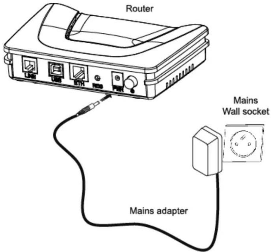
2.2.1 Connecting to a power socket
First connect the end of the mains cord, supplied with the equipment, to the PWR base of your router.
Connect the mains adapter to a nearby mains wall socket.
➢ Set the "On/Off" switch to On.
text_image
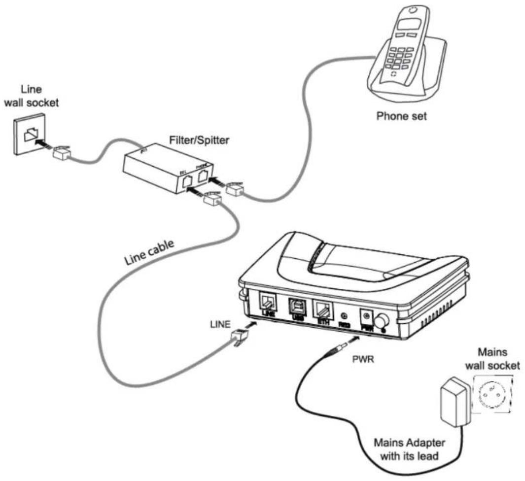
Router Mains Wall socket Mains adapter2.2.2 Connection of the ADSL cable to the router
Connect an end of the supplied grey RJ11/RJ11 cable to the grey fixed connector marked LINE of your router.
Connect the other end of this cable to the connector marked ADSL on the micro-filter connected to the RJ11 telephone wall socket of your home.
flowchart
graph TD
    A["Line wall socket"] --> B["Filter/Spitter"]
    B --> C["Line cable"]
    C --> D["Phone set"]
    D --> E["PWR"]
    E --> F["Mains wall socket"]
    F --> G["Mains Adapter with its lead"]
    G --> H["Line"]
2.2.3 Connecting to your computer
Two connections may have to be made:
➢ Connection of the USB interface of your router to your computer.
➢ Connection of the Ethernet interface of your router to your computer.
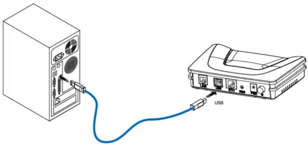
2.2.3.1 Connection of the USB interface of your router to your computer

This connection is made in all cases after installing the drivers of the USB interface (see section 3).
Connect the end of the blue USB cable fitted with a type B connector (square fixed connector) to the blue fixed connector marked USB of your router,
Connect the other end of the cable fitted with a type A connector (rectangular fixed connector) to your computer.
natural_image
Diagram showing connection between a server unit and an electronic device via USB cable (no text or symbols present)2.2.3.2 Connecting the Ethernet interface of your router to your computer
Connect the end of the yellow Ethernet cable (RJ45/RJ45) supplied in the pack to the yellow Ethernet fixed connector marked ETH of your router,
Connect the other end of the cable to your computer.

natural_image
Diagram showing a computer tower connected to an Ethernet device via cable (no text or symbols present)2.3 Installation instructions
Environment
The router must be installed and used inside a building.
The ambient temperature must not exceed 45^ C.
The router must not be exposed to direct strong sunlight nor to an intense heat source.
The router must not be placed in an environment subject to vapour condensation.
The router must not be exposed to water projections.
The router unit must not be covered.
Power source
Use a network socket with easy access, which is close to the equipment. The power cord is 2 m in length.
➢ Arrange the power cord so as to prevent any accidental power cutoff of the router.
The router is designed to be connected to a TT or TN type power network.
The router is not designed to be connected to an electrical installation with an IT type diagram (neutral connected to earth through an impedance).
Protection against short circuits and inter-phase leakages, neutral and earth must be made by the building's electrical installation. The power circuit of this equipment must be fitted with a 16 A protection against power surges, and with a differential protection.
Maintenance
It is prohibited to open the case. Only qualified personnel approved by your supplier may do so.
Do not use liquid or spray cleaning agents.
3. Installing and configuring the router
| This section covers | ➢ installing your router with the network card of your computer (Ethernet). | § 3.1 |
| ➢ installing your router in the USB port of your computer. | § 3.2 | |
| ➢ installing an additional computer. § 3.3 |
3 - Installing and configuring the router
Your router can be installed and configured with the following interfaces:
➢ Ethernet (ETH)(cf. § 3.1),
USB (cf. § 3.2).

Before installing your router, we recommend you uninstall every ADSL router.

The installation procedure described below was undertaken in Windows® XP. Installation in other Windows operating systems® (98, ME and 2000) can be slightly different.
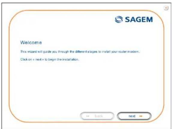
1 Insert the CD-ROM in the appropriate driver of your computer; the screen opposite is displayed.
Click button installation.

to start the
text_image
Welcome This wizard will guide you through the different stages to install your router modem. Click on « next » to begin the installation.Observation: If this screen does not appear: Select, in the menu Start, the command Execute, then enter:
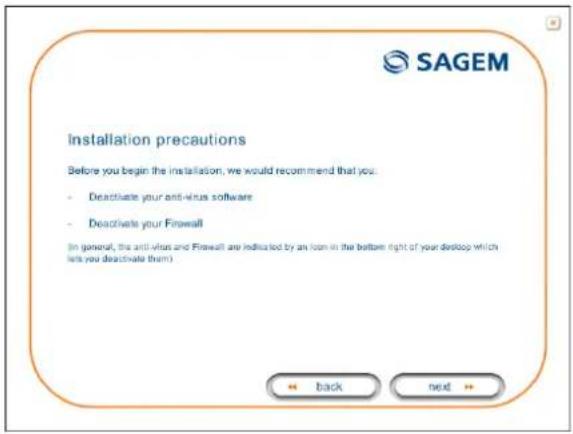
2 The screen opposite appears.
Carry out the operations described on the screen.
Click button next to continue the installation.
text_image
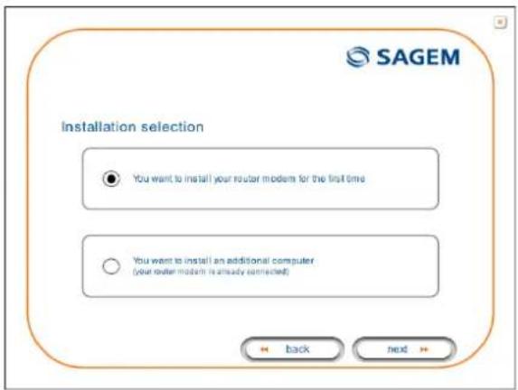
Installation precautions Before you begin the installation, we would recommend that you: - Deactivate your anti-virus software - Deactivate your Firewall (In general, the anti-virus and Firewall are indicated by an icon in the bottom right of your desktop which lets you deactivate them) + back next +3 A screen enabling the type of installation to the chosen (first installation or installation of an additional computer) appears.
For a first installation, we recommend that you check the button

text_image
You want to install your router modem for the first timethen click on to continue the installation.
text_image
Installation selection ● You want to install your router model for the first time ○ You want to install an additional computer (your router model is already connected) Back next4 The screen opposite appears.
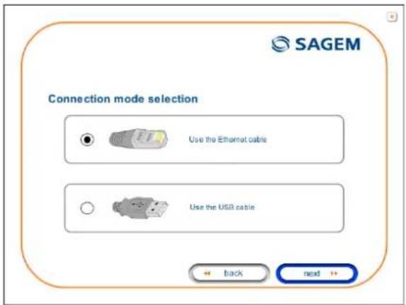
This screen enables you to choose to which interface (Ethernet or USB) you wish to connect your router to your computer.
Select the interface required and then click button next to continue the installation.
text_image
SAGEM Connection mode selection Use the Ethernet cable Use the USB cable Back nextThe installation of your router using different interfaces is described in detail below in the order displayed on the previous screen (choice of connection mode).
3.1 Installing and configuring your Router with the network card of your computer (Ethernet)
The Ethernet fixed connector marked ETH of your router is designed for connecting your computers or wired Ethernet network equipment. It supports 10 Mbit/s and 100 Mbit/s transmission rates in Half or Full Duplex mode on a category 5 double twisted pair cable.
This port is a RJ45 connector with wiring of the self-detecting MDI or MDI-x type.
With this port, you can connect using a straight or crossed Ethernet cord:
- either directly to a computer equipped with a 10/100BASE-T Ethernet network,
• or to an Ethernet local network connected to a network concentrator (HUB or Switch).

The installation procedure described below was undertaken in Windows® XP. Installation in other Windows operating systems® (98, ME and 2000) can be slightly different.
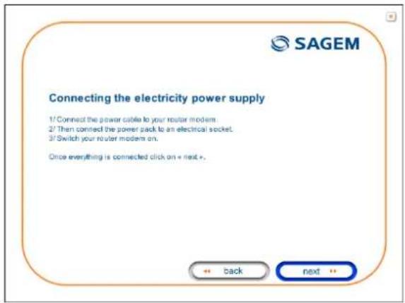
1 You have selected the Ethernet interface; the screen opposite appears.
Make the electrical connection as described on the screen.
Click button next to continue the installation.
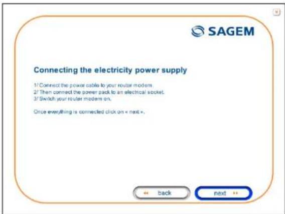
text_image
SAGEM Connecting the electricity power supply 1/ Connect the power cable to your router modems. 2/ Then connect the power pack to an electrical socket. 3/ Switch your router modems on. Once everything is connected click on « next ». ← back next ←2 The screen opposite appears.
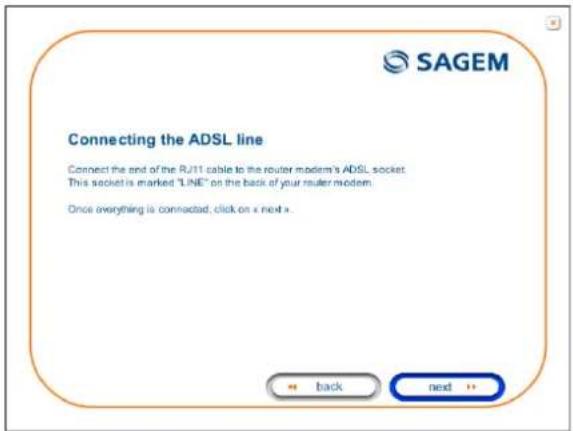
Make the connection of the ADSL line as described on the screen.
Click button next to continue the installation.
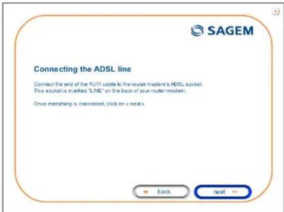
text_image
SAGEM Connecting the ADSL line Connect the end of the RJ11 cable to the router modem's ADSL socket. This socket is marked "LINE" on the back of your router modem. Once everything is connected, click on x next x.3 Connect the Ethernet cable as described on the screen.
Click button next to continue the installation.
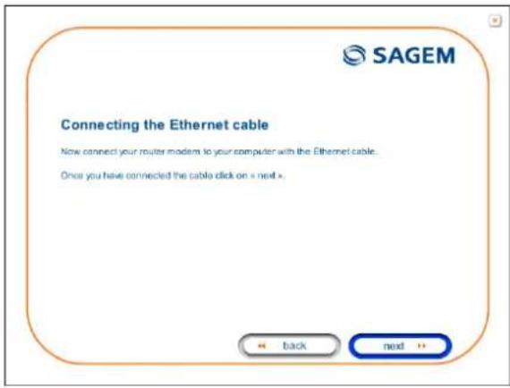
text_image
SAGEM Connecting the Ethernet cable Now connect your router modern to your computer with the Ethernet cable... Once you have connected the cable click on » next > ← back → next →4 The screen opposite appears and asks you to wait.
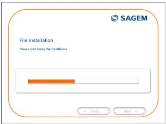
text_image
File installation Please wait during the installation.5 The screen opposite appears.
Please wait during the diagnostics of the connection to the Router via an Ethernet cable.
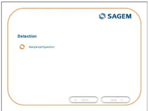
text_image
Detection dongite configuration SAGEM + - Back + - Next + -3 - Installing and configuring the router
6 The screen opposite appears.
Enter the connection identifier followed by the connection password.
The latter are available from your subscription confirmation letter.
Click button next to continue the installation.
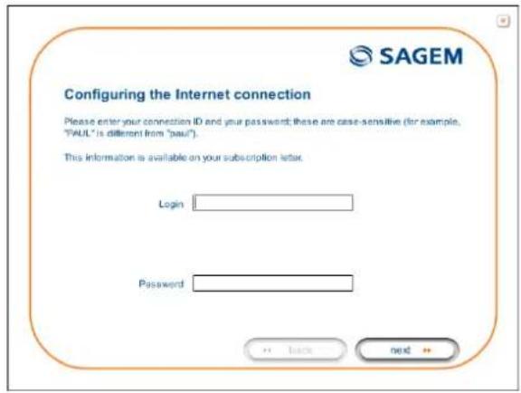
text_image
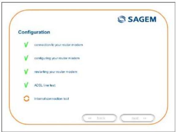
SAGEM Configuring the Internet connection Please enter your connection ID and your password; these are case-sensitive (for example, "PAUL" is different from "paul"). This information is available on your subscription letter. Login Password ← Back → next →7 The screen opposite appears and asks you to wait during the successive diagnostics.
The rotating orange arrows are replaced by a green check mark after each successful test.

text_image
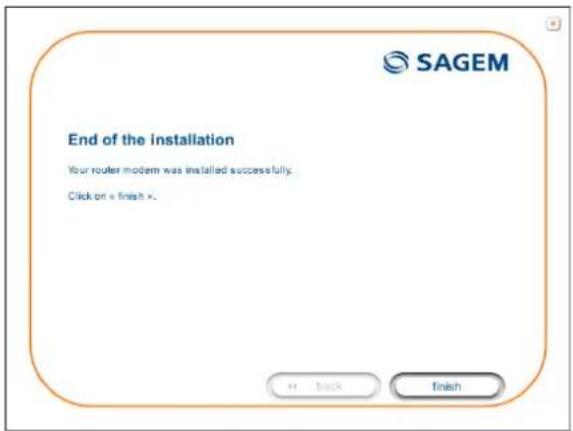
Configuration ✓ connection to your router modem ✓ configuring your router modem ✓ restarting your router modem ✓ ADSL line test ✓ Internal connection test SAGEM8 The screen opposite appears.
The installation has been correctly accomplished; your router is operational.
Click button the window.


text_image
End of the installation Your router modem was installed successfully. Click on « finish ». + Back Finish9 The "SAGEM" welcome screen appears.
You can now use your Internet access.
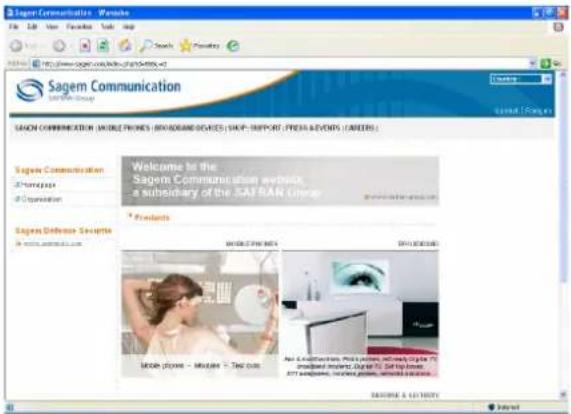
text_image
Sagem Communication - Website File Edit View Favorites Help Help Sagem Communication (MOBILE PRIMES / BROADCAST SERVICES) SHAP: SUPPORT / PRESS EVENTS / CAREERS Welcome to the Sagem Communication website a extraordinary of the SAFRAN Group Products MOBILE PRIMES SHAP TARGETS MOORE PRAVE - MULBEE - Test OUT Any 3D/4D/5D/6D/7D/8D/9D/10D/11D/12D/13D/14D/15D/16D/17D/18D/19D/20D/21D/22D/23D/24D/25D/26D/27D/28D/29D/30D/31D/32D/33D/34D/35D/36D/37D/38D/39D/40D/41D/42D/43D/44D/45D/46D/47D/48D/49D/50D/51D/52D/53D/54D/55D/56D/57D/58D/59D/60D/61D/62D/63D/64D/65D/66D/67D/68D/69D/70D/71D/72D/73D/74D/75D/76D/77D/78D/79D/80D/81D/82D/83D/84D/85D/86D/87D/88D/89D/90D/91D/92D/93D/94D/95D/96D/97D/98D/99D/100 SAGEM & LUTTERLY Download3.2 Installing and configuring your Router in the USB port of your computer
The USB port of your router is of the USB 1.1 type allowing a maximum transmission rate of 12 Mbit/s.
With this port, you can connect directly to a computer located at a type A USB input, using a USB cord (supplied with the equipment).

The USB interface must in all cases be installed before the USB connector is connected.

The installation procedure described below was undertaken in Windows® XP. Installation in other Windows operating systems® (98, ME and 2000) can be slightly different.
1 You have selected the USB interface; the screen opposite appears.
Make the electrical connection as described on the screen.
Click button next to continue the installation.
text_image
Connecting the electricity power supply 1/Connect the power cable to your router modem. 2/Then connect the power pack to an electrical socket. 3/Switch your router modem on. Once everything is connected click on « next ». ← back next +2 The screen opposite appears.
Make the connection of the ADSL line as described on the screen.
Click button next to continue the installation.
text_image
SAGEM Connecting the ADSL line Connect the end of the RJ11 cable to the router modem's ADSL socket. This socket is marked "LINE" on the back of your router modem. Once everything is connected, click on x next x.3 The screen opposite appears and asks you to wait.
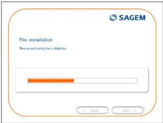
text_image
File installation Please wait during the installation.4 Connect the USB cable as described on the screen.
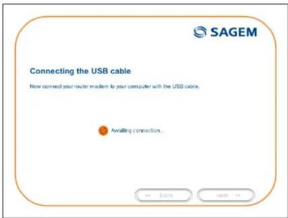
text_image
Connecting the USB cable Now connect your router modem to your computer with the USB cable. Awaiting connection...5 The screen opposite appears. Please wait during the diagnostics of the connection to the Router via a USB cable.
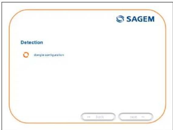
text_image
Detection dongite configuration SAGEM3 - Installing and configuring the router
6 The screen opposite appears.
Enter the connection identifier followed by the connection password.
The latter are available from your subscription confirmation letter.
Click button next to continue the installation.

text_image
SAGEM Configuring the Internet connection Please enter your connection ID and your password; these are case-sensitive (for example, "PAUL" is different from "paul"). This information is available on your subscription letter. Login Password ← Back → next →7 The screen opposite appears and asks you to wait during the successive diagnostics.
The rotating orange arrows are replaced by a green check mark after each successful test.
text_image
Configuration ✓ connection to your router modem ✓ configuring your router modem ✓ restarting your router modem ✓ ADSL line test ✓ Internal connection test SAGEM8 The screen opposite appears.
The installation has been correctly accomplished; your router is operational.
Click button the window.

text_image
End of the installation Your router modem was installed successfully. Click on « finish ». + Back Finish9 The "SAGEM" welcome screen appears.
You can now use your Internet access.

text_image
Sagem Communication - Website File Edit View Favorites Web Help Sagem Communication (MOBILE PRIMES / BROADCAST SERVICES) (SAP: SUPPORT, PRESS & EVENTS / CAREERS) Welcome to the Sagem Communication website a mandatory of the SAFRAN Group Products Sagem Defense Security www.sagemd.com SAGEM & LATIVITY SAGEM Communication (MOBILE PRIMES / BROADCAST SERVICES) (SAP: SUPPORT, PRESS & EVENTS / CAREERS)
If you wish to install your router with another interface, you must imperatively uninstall your router.
To do this:
Select Start/All programs/SAGEM F@st™ 1201/Uninstall
3.3 Installing and configuring an additional computer
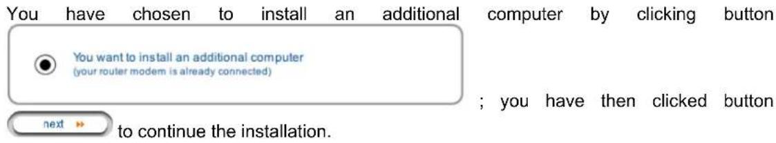
text_image
You have chosen to install an additional computer by clicking button You want to install an additional computer (your router modem is already connected) ; you have then clicked button next → to continue the installation.1 The screen opposite appears.
This screen enables you to choose to which interface (Ethernet or USB) you wish to connect your router to your computer.
Click "Use the Ethernet cable" (cf. § 3.1),
Click "Use the Ethernet cable" (cf. § 3.2),
and then click button next to continue the installation.
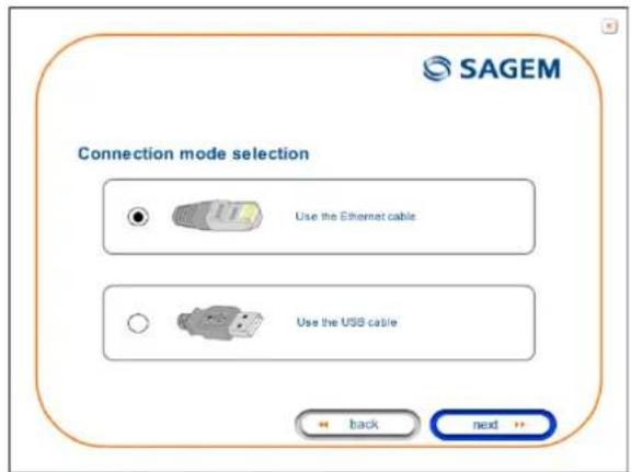
text_image
SAGEM Connection mode selection Use the Ethernet cable Use the USB cable ← back → next →
The stages concerning:
- The electrical connection and connection to the ADSL line of the router,
- Together with configuration of the router (connection identifier, connection password, etc.).
are no longer to be accomplished when installing an additional computer, whatever the interface (Ethernet or USB).
4. Configuration of network parameters
| This section covers | ➢ configuring as a DHCP client | Page 4-3 |
| ➢ reading data of the DHCP server Page 4-4 | ||
| ➢ reading data of the DHCP client Page 4-6 |
4 - Configuration of network parameters
The aim of this section is:
1) to configure your computer so that it is able to communicate with your router.
2) and to display the "Networks" parameters of your router.
Your router implements the DHCP (Dynamic Host Configuration Protocol) server, relay and client functions in accordance with RFC 2131 and RFC 3132, whereas the computer connected directly to the router or via a local network by its LAN interface implements only the DHCP client function.
On receipt of a DHCP query from your computer (see ⚠️), whether or not it is connected to your router, the latter responds by indicating:
- an address from the range defined in the configuration,
- the sub-network mask,
- the default gateway (address of your router),
- the address of the gateway as DNS server. The "DNS Relay" function is activated automatically.

The configured range of IP addresses must be the same in the sub-network as in the LAN interface.

It is imperative that your computer is configured as a DHCP client or that it has a fixed IP address in the configuration range defined by the DHCP server.
Configuration as a DHCP client is the more commonly used solution.
1) Configuring as a DHCP client
In Windows XP
- Click on Start/Control Panel/Network Connections.
- Right-click on the network which you are using, and then select Properties.
- Click on protocol TCP/IP of the network card, and then click on Properties.
The screen opposite appears.
- Select the general tab, then the command "Obtain an IP address automatically" and the command "Obtain the addresses of the DNS servers automatically".
- Click button OK to confirm your choice.
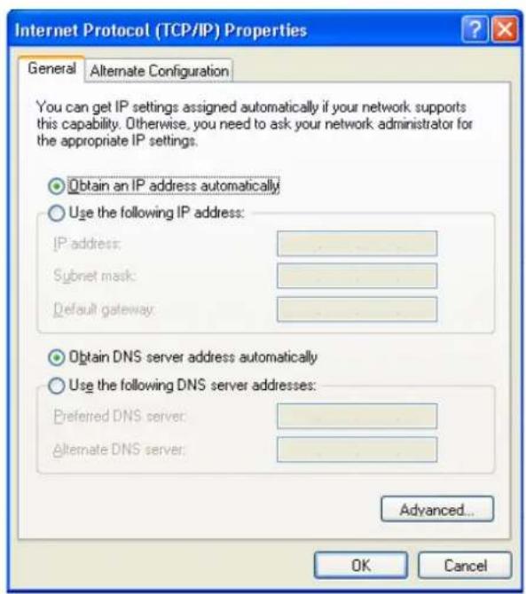
text_image
Internet Protocol (TCP/IP) Properties General Alternate Configuration You can get IP settings assigned automatically if your network supports this capability. Otherwise, you need to ask your network administrator for the appropriate IP settings. Obtain an IP address automatically Use the following IP address: IP address: Subnet mask: Default gateway: Obtain DNS server address automatically Use the following DNS server addresses: Preferred DNS server: Alternate DNS server: Advanced... OK Cancel2) Data of the DHCP server
To obtain this data:
- Open your browser and then enter http://myrouter or http://192.168.1.1 (default IP address of the router) to access the welcome screen,
- Click the "LAN" menu of the heading Advanced Setup; the following screen appears:
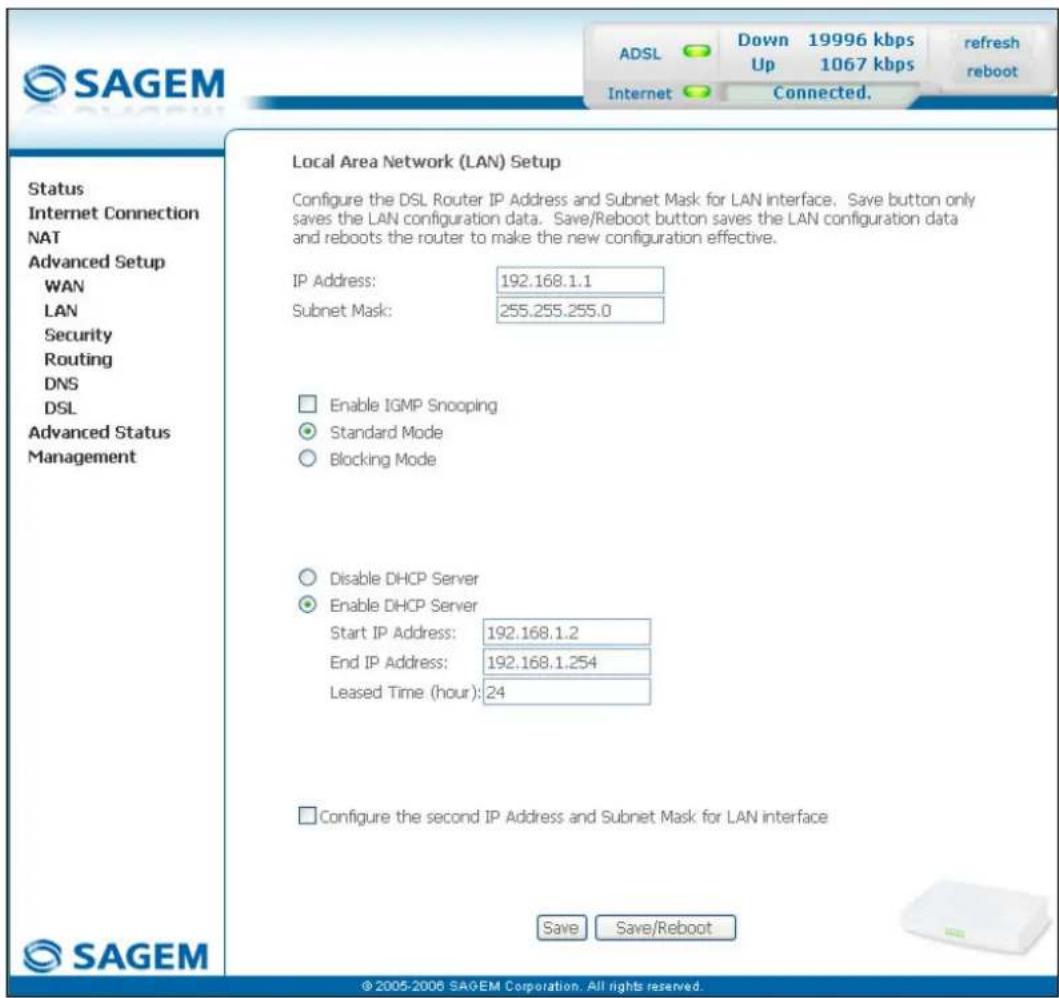
text_image
SAGEM ADSL Down 19996 kbps Up 1067 kbps refresh reboot Internet Connected. Status Internet Connection NAT Advanced Setup WAN LAN Security Routing DNS DSL Advanced Status Management Local Area Network (LAN) Setup Configure the DSL Router IP Address and Subnet Mask for LAN interface. Save button only saves the LAN configuration data. Save/Reboot button saves the LAN configuration data and reboots the router to make the new configuration effective. IP Address: 192.168.1.1 Subnet Mask: 255.255.255.0 Enable IGMP Snooping Standard Mode Blocking Mode Disable DHCP Server Enable DHCP Server Start IP Address: 192.168.1.2 End IP Address: 192.168.1.254 Leased Time (hour): 24 Configure the second IP Address and Subnet Mask for LAN interface Save Save/Reboot © 2005-2006 SAGEM Corporation. All rights reserved.| Field Meaning | Display | |
| IP Address | Displays the sub-network address 192.168.1.1 | |
| Subnet Mask | Displays the sub-network mask of the IP network. 255.255.0 | |
| Start IP Address | Displays the first address attributed by the DHCP server.Note: This IP address must belong to the same sub-network as that of the local network. | 192.168.1.2 |
| End IP Address | Displays the last address attributed by the DHCP server.Note: This IP address must belong to the same sub-network as that of the local network. | 192.168.1.254 |
| Leased Time (hour) | Displays the period for obtaining (in hours) an IP address for a terminal. | 24 |
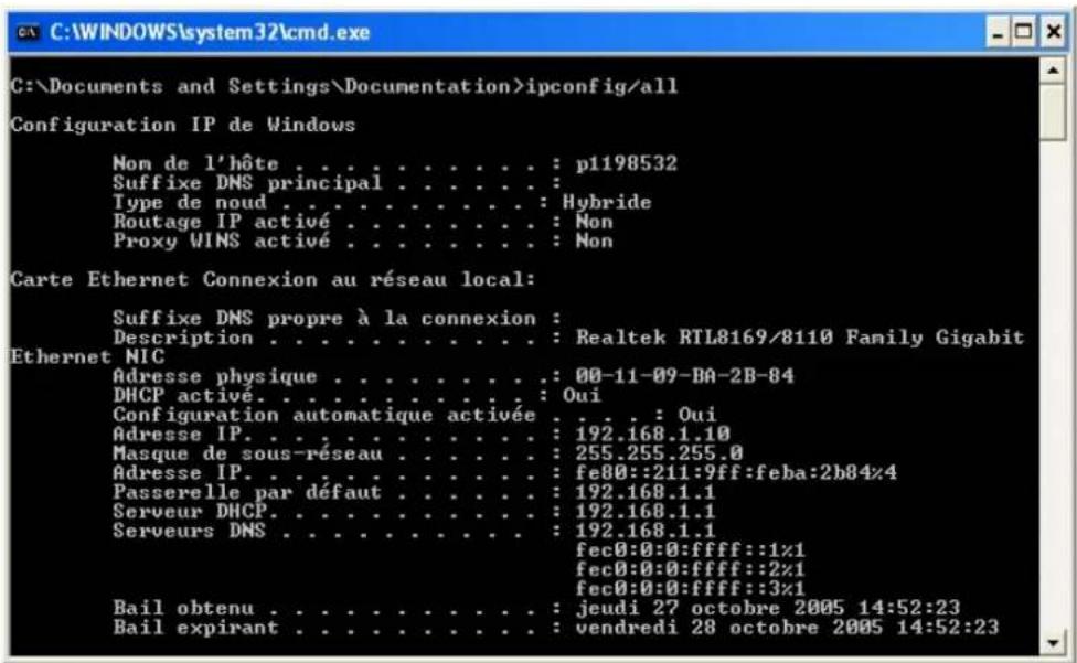
3) Data of the DHCP client
To obtain this data:
In Windows XP, 2000 and Me
Click button Start, select Execute, enter cmd and then click OK; the command prompt screen appears. Enter ipconfig /all (or ipconfig/all) then confirm by pressing Enter.
| This section covers ➢ Accessing the welcome screen § 5.1 | |
| ➢ Recommendations for using the configuration screens | § 5.2 |
| ➢ The ADSL connection status §.5.3 | |
| ➢ Indications displayed on the display frame located in the HTTP configurer window | § 5.4 |
| ➢ The "Status" section | § 5.5 |
| ➢ The "Internet Connection" section | § 5.6 |
| ➢ The "NAT" section | § 5.7 |
| ➢ The "Advanced Setup" section | § 5.8 |
| ➢ The "Advanced Status" section | § 5.9 |
| ➢ The "Management" section | § 5.10 |
5.1 Accessing the welcome screen

To access this screen, you must have configured your computer's network function Ethernet or USB interfaces using the installation CD-ROM provided with your router (cf. chapter 3).
If you are using your computer's Ethernet card to configure your router, connect it to the Ethernet port whose yellow socket is marked ETH.
Your router is then configured using a simple Web browser (e.g. Internet Explorer).

The router's DHCP server function is activated by default with an address range defined as indicated in §.5.8.2.
To access the configurer, proceed as follows:
1 In the Start menu, select All Programs / SAGEM F@st 1201, then left click on

Configuration
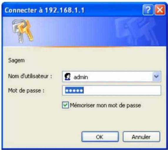
2 The following screen asks you to connect.
Enter admin by default in the "Username" field.
Enter admin by default in the "Password" field.
Then click on OK to confirm.
Note: The equipment's IP address (192.168.1.1) appears in the bar at the top of the screen.
3 Your computer's Web browser opens and displays the router's welcome screen. The equipment's name is displayed in title.
Equipment configuration sections appear in the left hand area in the welcome screen.
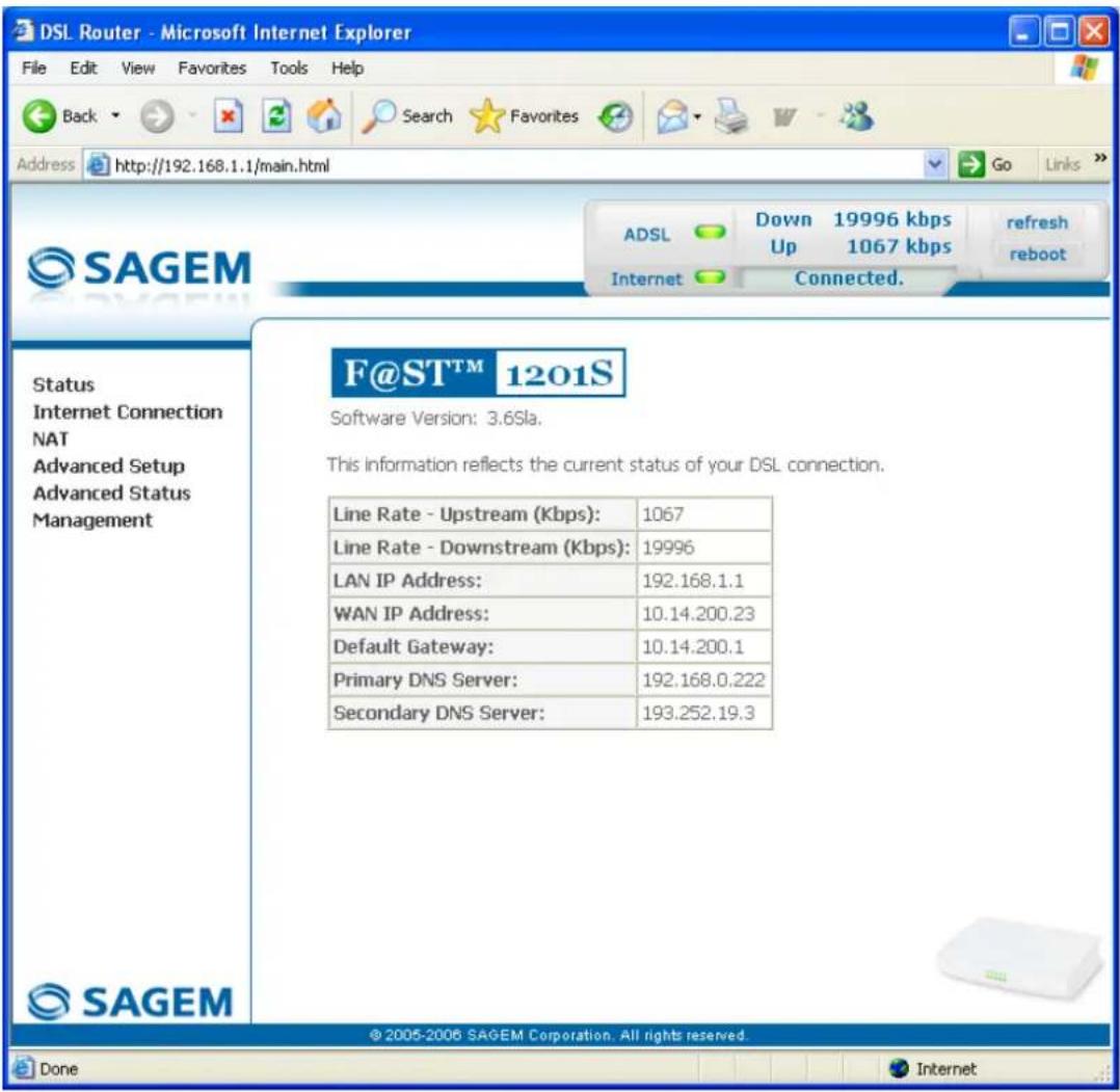
text_image
DSL Router - Microsoft Internet Explorer File Edit View Favorites Tools Help Back Search Favorites Address http://192.168.1.1/main.html Go Links >> SAGEM ADSL Down 19996 kbps refresh Up Up 1067 kbps reboot Internet Connected. Status Internet Connection NAT Advanced Setup Advanced Status Management F@ST™ 1201S Software Version: 3.6Sla. This information reflects the current status of your DSL connection. Line Rate - Upstream (Kbps): 1067 Line Rate - Downstream (Kbps): 19996 LAN IP Address: 192.168.1.1 WAN IP Address: 10.14.200.23 Default Gateway: 10.14.200.1 Primary DNS Server: 192.168.0.222 Secondary DNS Server: 193.252.19.3 © 2005-2006 SAGEM Corporation. All rights reserved. Done InternetThis screen displays:
in the centre, an area which shows the current ADSL connection status (cf. § 5.3).
in the top right, a display box which lets you know the status of the ADSL line, lets you refresh the window displayed and restart your router at any time (cf. § 5.4).
to the left, a list of 6 sections (cf. § 5.5 to 5.10) made up of menus and sub-menus. These let you view and configure your router's parameters.

You can modify the password to access your router's configurer to optimise the safety of your network.
5.2 Recommendations
The meaning of the main buttons most commonly present in all the configuration windows is provided in the table below.
| Add | Click on this button to add a new window to fill in the fields used to add an object. |
| Back | Click on this button to return to the previous screen. |
| Close | Click on this button to close the active window and return to the main screen. |
| Edit | Click on this button to display a new window to modify the fields that can be accessed for a previously selected object. |
| Next | Click on this button to display the next screen. |
| Remove | Click on this button to remove a selected object from a list.Note: You must check the "Remove" box to delete this object. |
| Save | Click on this button to save the entry in the router's non-volatile (flash) memory.Note: This value will only be taken into account when you restart your router. |
| Save/Apply | Click on this button to save the entry in the router's non-volatile (flash) memory.Note: This value will be taken into account immediately without you having to restart your router. |
| Save/Reboot | Click on this button to save the entry in the router's non-volatile (flash) memory then restart your computer. |
Basic principles
1) To make this guide easier to read and understand, it does not state that each time you enter information into a screen you must click on Save or Save/Apply or Save/Reboot (except, of course, if this is necessary).
2) When you select a section, the screen for the first menu in the section is displayed. In the same way, when you select a menu, the screen for the first sub-menu is displayed.
3) All the fields in the different screens are explained in a table.
5.3 ADSL connection status
Refer to § 5.5.1 - Status/Summary.
5.4 Display frame

text_image
ADSL Down 19996 kbps Up 1067 kbps refresh reboot Internet Connected.This supervision box is displayed permanently at the top right of each HTTP configurer window.
The different objects it contains are explained below.
LEDs
| ADSL | Green | Synchronised ADSL line | |
| Yellow | ADSL line synchronising | ||
| Red | ADSL line not connected | ||
| Internet | Green Connected | Public address (WAN) distributed to the router. | |
| Yellow Waiting for ISP | ADSL line synchronising or public address (WAN) not distributed to the router | ||
| Off | ADSL Down | Public address (WAN) not distributed to the router, or ADSL line not synchronised. | |
| Not configured | No VC (Virtual Channel) configured | ||
| Router Rebooting | Router restarted | ||
| Red Access denied | Wrong Login and/or Password | ||
Transmission rates
| Down | Displays the nominal down line transmission rate |
| Up | Displays the nominal up line transmission rate |
Buttons
| refresh | Allows data displayed on the screen to be refreshed |
| reboot | Allows your router to be started |
5.5 Status
Clicking on this heading displays the following menus:
• Summary (cf. 5.5.1),
• Diagnostics (cf. 5.5.2).
5.5.1 Summary
Object: This menu lets you display the current status of your Internet connection.
- Select the Summary menu in the Status section; the following screen opens:
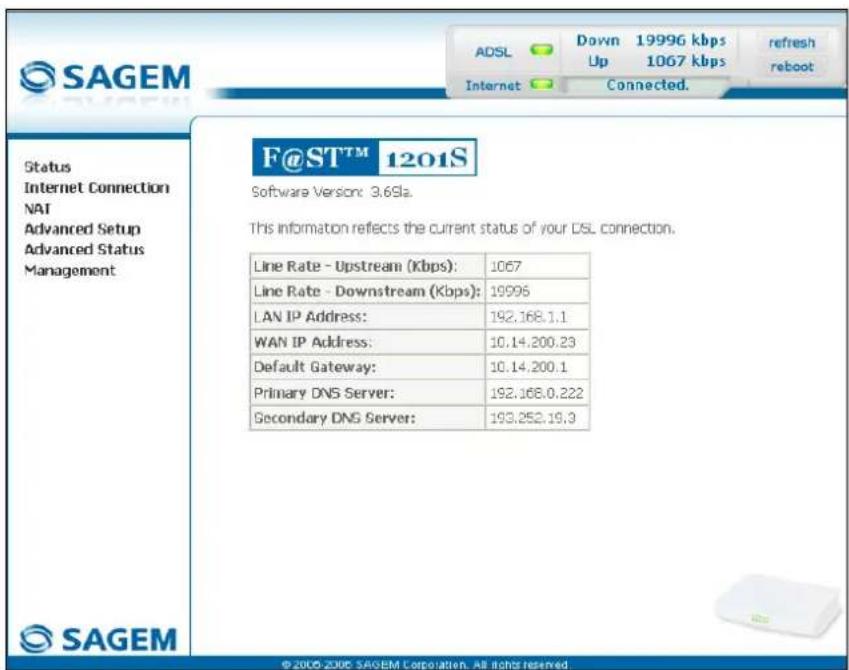
text_image
SAGEM ADSL Down 19996 kbps Up 1067 kbps Internet Connected. Refresh reboot Status Internet Connection NAT Advanced Setup Advanced Status Management F@ST™ 1201S Software Version: 3.69la. This information reflects the current status of your DSL connection. Line Rate - Upstream (Kbps): 1067 Line Rate - Downstream (Kbps): 19996 LAN IP Address: 192.168.1.1 WAN IP Address: 10.14.200.23 Default Gateway: 10.14.200.1 Primary DNS Server: 192.168.0.222 Secondary DNS Server: 193.252.19.3 © 2005-2006 SAGEM Corporation. All rights reserved.
This screen also appears in the welcome screen (see § 5.1).
The following table provides the meaning of the different fields which are displayed.
| Field Meaning | |
| Software Version | Software version currently installed. |
| Line Rate - Upstream (kbps) | Nominal up line rate |
| Line Rate - Downstream (kbps) | Nominal down line rate |
| LAN IP Address | Local network IP address (LAN) |
| WAN IP Address | Remote network IP address (WAN) |
| Default Gateway | Default gateway address |
| Primary DNS Server | Primary DNS server address |
| Secondary DNS Server | Secondary DNS server address |
5.5.2 Diagnostics
Object: This menu is used to display all the tests performed on the connections made from your router to your Internet Service Provider (ISP). These tests concern:
- the connection to your local network (LAN),
- the connection to your "DSL Service Provider",
- Connection to your "Internet Service Provider".

A hypertext link (help) enables the user to access context-related help. This help gives an explanation concerning the state of the connection (PASS in green, DOWN in orange and FAIL in red) and supplies the appropriate troubleshooting procedures.
The ADSL line translates the three statuses detailed in the table below.
| State Colour Meaning | |
| PASS Green | Indicates that the test was completed successfully. |
| DOWN Orange | Indicates that an interface (ETH or USB) has not been detected. |
| FAIL Red | Indicates that the test has failed, or that it is impossible to start a command. |

If a test displays a "FAIL" state, click on "Help" and then the button "Rerun Diagnostic Tests" at the bottom of the "Help" page, to check that the test has been conclusive. If the test still displays "FAIL", you must follow the troubleshooting procedure displayed on this page.
5 - Information / Configuration
- Select the Diagnostics menu in the Status section; the following screen opens:
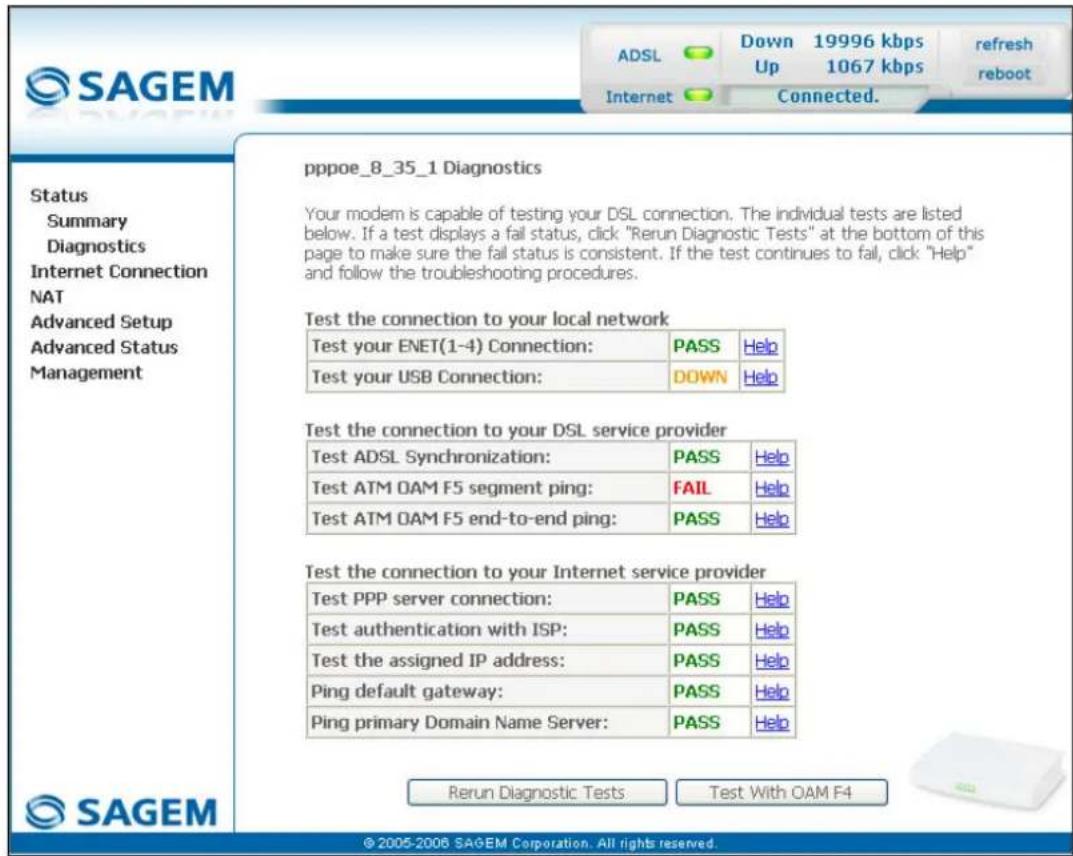
text_image
SAGEM ADSL Down 19996 kbps Up 1067 kbps Refresh reboot Internet Connected. Status Summary Diagnostics Internet Connection NAT Advanced Setup Advanced Status Management pppoe_8_35_1 Diagnostics Your modem is capable of testing your DSL connection. The individual tests are listed below. If a test displays a fail status, click "Rerun Diagnostic Tests" at the bottom of this page to make sure the fail status is consistent. If the test continues to fail, click "Help" and follow the troubleshooting procedures. Test the connection to your local network Test your ENET(1-4) Connection: PASS Help Test your USB Connection: DOWN Help Test the connection to your DSL service provider Test ADSL Synchronization: PASS Help Test ATM OAM F5 segment ping: FAIL Help Test ATM OAM F5 end-to-end ping: PASS Help Test the connection to your Internet service provider Test PPP server connection: PASS Help Test authentication with ISP: PASS Help Test the assigned IP address: PASS Help Ping default gateway: PASS Help Ping primary Domain Name Server: PASS Help SAGEM Rerun Diagnostic Tests Test With OAM F4 © 2005-2006 SAGEM Corporation. All rights reserved.5.6 Internet Connection
Object: This menu lets you enter your connection ID and your connection password.
- Select the Internet Connection heading to display the following connection configuration screen:
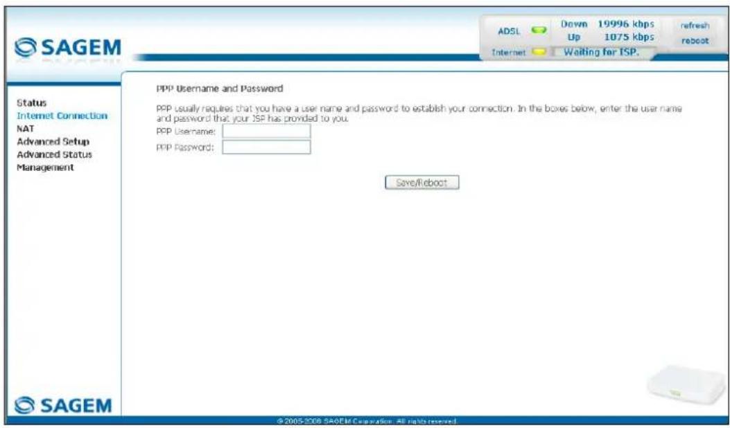
text_image
SAGEM ADSL Down 19996 kbps refresh Up 1075 kbps reboot Internet Waiting for TSP. Status Internet Connection NAT Advanced Setup Advanced Status Management PPP Username and Password PPP usually requires that you have a user name and password to establish your connection. In the boxes below, enter the user name and password that your JSP has provided to you. PPP Username: PPP Password: Save/Reboot © 2005-2008 SAGEM Corporation. All rights reserved.| Field Action Default: | ||
| PPP Username | Enter your connection ID.This information is provided to you by your Internet Service Provider (ISP). | Empty |
| PPP Password | Enter your connection password.This information is provided to you by your Internet Service Provider (ISP). | Empty |

If the message "There is no ppp connection" appears, this means that the remote network (WAN) parameters have not been filled in (cf. § - 5.8.1 - Advanced Setup / WAN).
5.7 NAT
Object: NAT is a configurable IP address translation function which will be applied to the interfaces of your router which you will have activated for this function. Several translation function configurations, the NAT actions, can be configured and may be activated as indicated in the 5.7.1 - Add paragraph.
This section contains the following two menus:
- Port forwarding (cf. § 5.7.1),
• DMZ Host (cf. § 5.7.2),
5.7.1 Port forwarding
Object: This menu is used to route directly to the External Ports the incoming data from a Service server (such as, for example, FTP Server, SNMP, TFTP etc.) of the remote network (WAN) to computers on the local network (LAN) via the Internal Ports.
- Select the Port forwarding menu in the NAT section to display the following screen:
NAT - Virtual Servers Setup
Virtual Server allows you to direct incoming traffic from WAN side (identified by Protocol and External port) to the Internal server with private IP address on the LAN side. The Internal port is required only if the external port needs to be converted to a different port number used by the server on the LAN side. A maximum 32 entries can be configured.
Add Remove
| Server Name | External Port Start | External Port End | Protocol | Internal Port Start | Internal Port End | Server IP Address | Remove |

© 2005 SAGFM Corporation. All rights reserved.
| Field Meaning | |
| Server NameSelect a ServiceCustom Server | Service available over Internet (such as, for example FTP Server, SNMP, TFTP etc.). |
| Name you want to allocate to a local server. | |
| External Port Start | Internal start port (WAN side). |
| External Port End | Internal end port (WAN side). |
| Protocol | Transport protocol (TCP, UDP or TCP/UDP). |
| Internal Port Start | Internal start port (LAN side). |
| Internal Port End | This internal end port (LAN side) is associated with the external end port (WAN) side.Note: This cannot be modified. |
| Server IP Address | Computer address delivered by your router's DHCP server. |
Add
- Click on the Add button; the following screen appears:
NAT -- Virtual Servers
Select the service name, and enter the server IP address and click "Save/Apply" to forward IP packets for this service to the specified server. NOTE: The "Internal Port End" cannot be changed. It is the same as "External Port End" normally and will be the same as the "Internal Port Start" or "External Port End" if either one is modified.
Remaining number of entries that can be configured:32
Server Name:
Select a Service:
Select One
○ Custom Server:
The Ground Truth image displays a single, solid horizontal line. According to Rule 2 (UNDERSCORE & LINE RULES), this is a stylistic or background line, not a placeholder underscore. Therefore, the OCR result must ignore it and output nothing or only meaningful text. The provided OCR content is "____", which consists of four underscores. This is an incorrect interpretation of the line as a placeholder, violating the rule that stylistic lines must be ignored. The OCR has hallucinated underscores where none should exist based on the GT's visual context. Hence, the OCR result is inconsistent with the Ground Truth.
Server IP Address:
192.168.1.
Save/Apply
| External Port Start External Port End | Protocol Internal Port Start Internal Port End | |||||||
| TCP | √ | |||||||
| TCP | √ | |||||||
| TCP | √ | |||||||
| TCP | √ | |||||||
| TCP | √ | |||||||
| TCP | √ | |||||||
| TCP | √ | |||||||
| TCP | √ | |||||||
| TCP | ||||||||
| TCP | √ | |||||||
| TCP | √ | |||||||
| TCP | √ | |||||||
| TCP | √ | |||||||
| TCP | √ | |||||||
Save/Apply

© 2005 SAGEM Corporation. All rights reserved.
Proceed as follows:
Check the "Select a Service" box, then select the service of your choice from the scroll down list, for example "SNMP".
The "External Port Start", "External Port End", "Internal Port Start", "Internal Port End" and Protocol fields (transport protocol associated with this service) are automatically filled in the table.
Note: You may complete the table by adding other ports associated with a protocol.
or
➢ Check the "Custom Server" box, enter the name of the server you want to connect to, then:
- Complete the ID Host of your computer's IP address (this is attributed by your router's DHCP server).
- Fill in the "External Port Start", "External Port End", "Internal Port Start", "Internal Port End" and "Protocol" fields.
A few rules for entering values:
When you want to select a single port, the start port ("External Port Start" or "Internal Port Start") and the end port ("External Port End" or "Internal Port End") must be identical.
When you want to select a range of ports, the start port number must be lower than the end port number.
You must always start entering with the "External Port Start" and "External Port End" ports,
When you allocate a number to an "External Port Start", the same number is automatically allocated to the "Internal Port Start" and identically for "External Port End",
5 - Information / Configuration
The following diagram contains an example:

flowchart
graph TD
    A["Service server (Delta Force 2 for example)"] --> B["Internet"]
    B --> C["Start external port : 3568"]
    B --> D["End external port : 3569"]
    B --> E["Protocol : UDP"]
    B --> F["LINE port"]
    F --> G["Router"]
    G --> H["Computer"]
    G --> I["ETH port"]
    I --> J["Start internal port : 3568"]
    I --> K["End internal port : 3569"]
    I --> L["Protocol : UDP"]
    I --> M["IP Address of the modem/router : 192.168.1.2"]
    G --> N["Computer"]
The "Delta Force 2" service is available on your computer via the external ports 3568 and 3569 (WAN side) and via the internal ports 3568 and 3569 (LAN side).
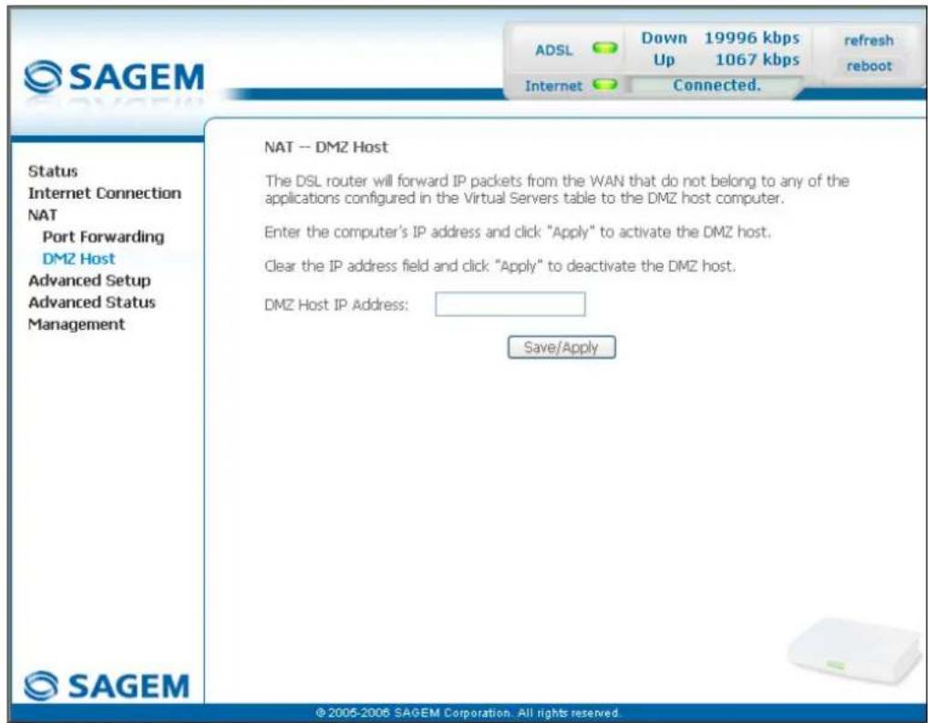
5.7.2 DMZ Host
Object: This "DMZ" (DeMilitarized Zone) lets you access the server you selected directly via the Internet without going through the "Firewall".

Caution, this process presents an intrusion risk. It is therefore vital that you take precautions so that no connections may be initiated to the private network.
- Select the DMZ Host menu in the NAT section to display the following screen:
text_image
SAGEM ADSL Down 19996 kbps Up 1067 kbps refresh reboot Internet Connected. Status Internet Connection NAT Port Forwarding DMZ Host Advanced Setup Advanced Status Management SAGEM NAT -- DMZ Host The DSL router will forward IP packets from the WAN that do not belong to any of the applications configured in the Virtual Servers table to the DMZ host computer. Enter the computer's IP address and click "Apply" to activate the DMZ host. Clear the IP address field and click "Apply" to deactivate the DMZ host. DMZ Host IP Address: Save/Apply ©2005-2006 SAGEM Corporation. All rights reserved.| Field Action Default | ||
| DMZ Host IP Address | Enter the IP address of a server to activate the "DMZ" and therefore access it directly from the Internet.To deactivate the "DMZ" zone, erase the address entered in the field.Note: Click on the Save/Apply button to take account of the address or its erasure. | Empty |

The "DMZ" zone is deactivated by default.
5.8 Advanced Setup
Object: This menu is used to configure the specific parameters for your router.

This menu must only be used by experienced users.
This section contains the following six menus:
- WAN (cf. § 5.8.1),
• LAN (cf. § 5.8.2),
• Security (cf. § 5.8.3), - Routing (cf. § 5.8.4),
• DNS (cf. § 5.8.5), - DSL (cf. § 5.8.6).
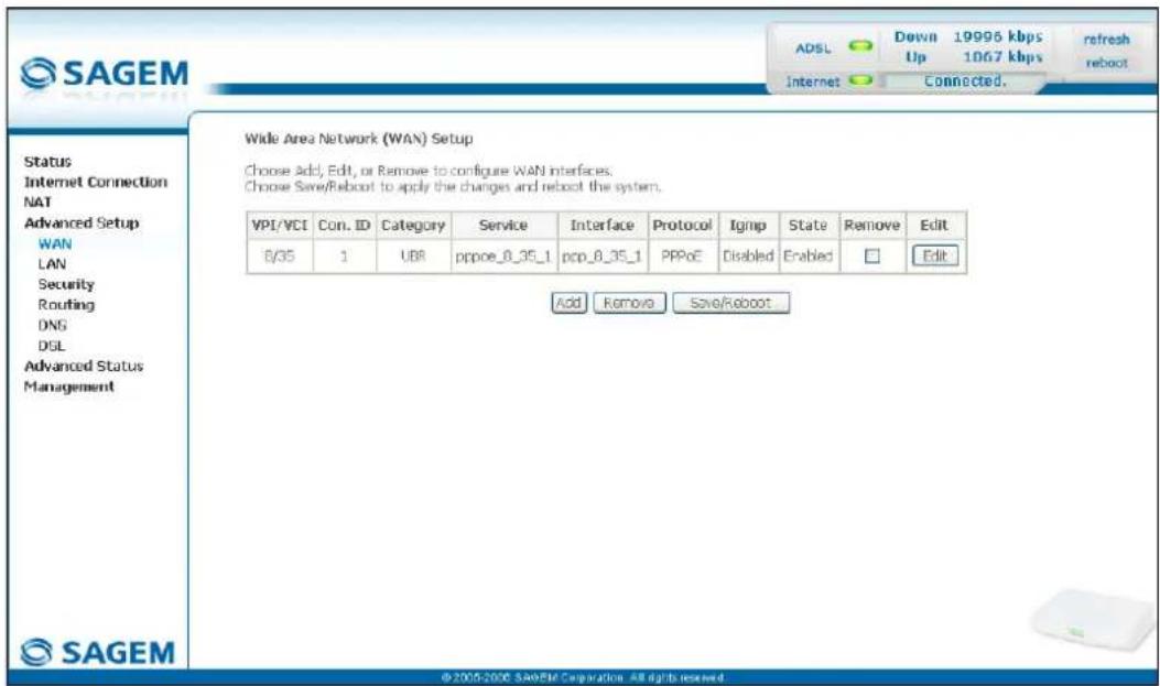
5.8.1 WAN
Object: This menu is associated with the remote network. It is used to display the list of all the configured PVCs, to add PVCs or remove them.
- Select the WAN menu in the Advanced Setup section to display the following screen:
text_image
SAGEM ADSL Down 19995 kbps refresh Up 1067 kbps reboot Internet Connected. Status Internet Connection NAT Advanced Setup WAN LAN Security Routing DNS DSL Advanced Status Management Wide Area Network (WAN) Setup Choose Add, Edit, or Remove to configure WAN interfaces. Choose Save/Reboot to apply the changes and reboot the system. VPI/VCI Con. ID Category Service Interface Protocol Ignip State Remove Edit B/35 1 UBR pppoe_8_35_1 pcp_8_35_1 PPPoE Disabled Enabled Edit Add Remove Save/Reboot © 2005-2006 SAGEM Corporation - All rights reserved| Field Meaning | |
| VPI/VCI | PVC identifier to configure. |
| Con. ID | Connection Identification. This is used to identify the different PPP connections which belong to the same PVC. To do so, you need only increment the "VC number" in the "Service" field when adding a new "PVC". |
| Category | ATM type of service |
| Service | Name of the ATM service. This name is made up as follows: VPI_VCI_Protocol_indexFor example: pppoe_0_35_1. |
| Interface | Name, allocated automatically, associated with the service name (for example, ATM interface "ppp_0_35_1" associated with the ATM service pppoe_0_35_1). |
| Protocol | Data flow encapsulation mode. |
| Igmp | Status (Enabled or Disabled) of the IGMP function. (see Note). |
| State | Status (Enabled or Disabled) of the WAN interface. |
Note: This function enables the distribution of Multicast datagrams over the local network (LAN) and interaction between the router and the local network hosts.
Add
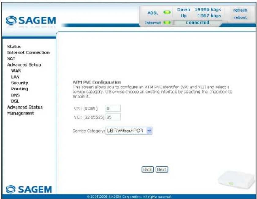
- Click on the Add button to display the following screen:
text_image
SAGEM ADSL Down 19996 kbps Up 1067 kbps Refresh reboot Internet Connected. Status Internet Connection NAT Advanced Setup WAN LAN Security Routing DNS DSL Advanced Status Management ATM PVC Configuration This screen allows you to configure an ATM PVC identifier (VPI and VCI) and select a service category. Otherwise choose an existing interface by selecting the checkbox to enable it. VPI: [0-255] 0 VCI: [32-65535] 35 Service Category: UBR Without PCR Back Next © 2006 2008 SAGEM Corporation. All rights reserved.ATM PVC Configuration
| Field Action Default | ||
| VPI | Enter a VPI value ^1 between 0 and 255. | 0 |
| VCI | Enter a VPI value ^1 between 32 and 65535. | 35 |
| Service Category | Select the type of service adapter to the traffic from the scroll down list:UBR without PCR : Unspecified Bit RateUBR with PCR : Unspecified Bit RateCBR : Constant Bit RateNon Realtime VBR : Variable Bit RateRealtime VBR : Variable Bit Rate | UBR without PCR |
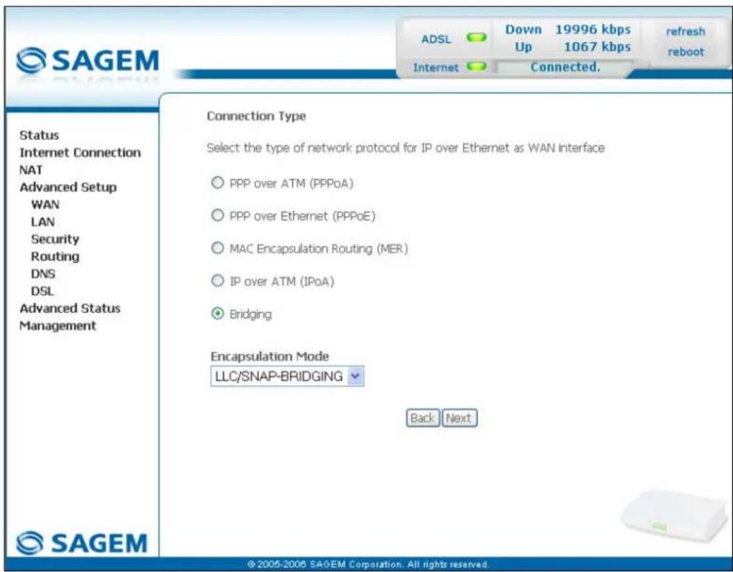
- Click on the Next button to continue configuring the remote network (WAN) and display the following screen:
text_image
SAGEM ADSL Down 19996 kbps refresh Up 1067 kbps reboot Internet Connected. Status Internet Connection NAT Advanced Setup WAN LAN Security Routing DNS DSL Advanced Status Management Connection Type Select the type of network protocol for IP over Ethernet as WAN Interface ○ PPP over ATM (PPPoA) ○ PPP over Ethernet (PPPoE) ○ MAC Encapsulation Routing (MER) ○ IP over ATM (IPoA) ● Bridging Encapsulation Mode LLC/SNAP-BRIDGING Back Next © 2005-2006 SAGEM Corporation. All rights reserved.
Depending on the type of network protocol selected, the encapsulation modes suggested in the scroll down list in the appropriate field are different.
Therefore, and to provide more clarity, a summary table will be presented below for each type of protocol.
PPP over ATM (PPPoA)
| Field Action Default | ||
| Encapsulation Mode | Select the encapsulation of your choice from the scroll down list.VC/MUX,LLC/ENCAPSULATION. | VC/MUX |
PPP over Ethernet (PPPoE)
| Field Action Default | ||
| Encapsulation Mode | Select the encapsulation of your choice from the scroll down list.LLC/SNAP-BRIDGING,VC/MUX. | LLC/SNAP-BRIDGING |
MAC Encapsulation Routing (MER)
| Field Action Default | ||
| Encapsulation Mode | Select the encapsulation of your choice from the scroll down list.LLC/SNAP-BRIDGING,VC/MUX. | LLC/SNAP-BRIDGING |
IP over ATM (IPoA)
| Field Action Default | ||
| Encapsulation Mode | Select the encapsulation of your choice from the scroll down list.LLC/SNAP-ROUTING,VC/MUX. | LLC/SNAP-ROUTING |
Bridging
| Field Action Default | ||
| Encapsulation Mode | Select the encapsulation of your choice from the scroll down list. • LLC/SNAP-BRIDGING, • VC/MUX. | LLC/SNAP-BRIDGING |
- Click on the Next button to continue configuring the remote network (WAN).

Depending on the type of network protocol (PPPoA, PPPoE, MER, IPoA or Bridging) selected earlier, the content of the following WAN interface configuration screens differs.
Therefore, and for more clarity, each type of protocol will be dealt with separately (screens + associated summary tables) below.
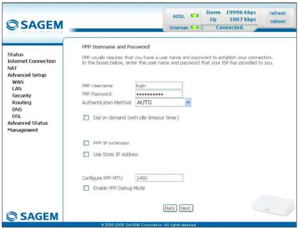
PPP over ATM (PPPoA)
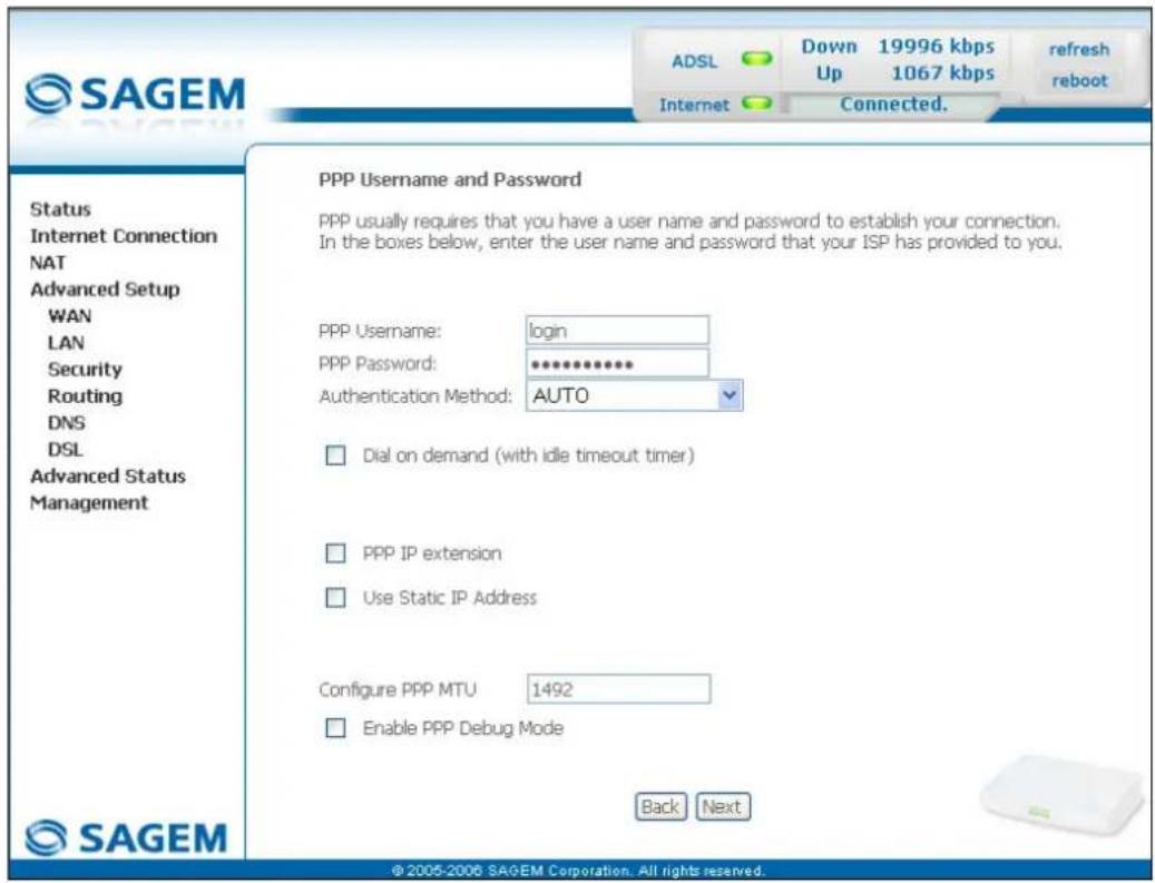
text_image
SAGEM ADSL Down 19996 kbps refresh Up 1067 kbps reboot Internet Connected. Status Internet Connection NAT Advanced Setup WAN LAN Security Routing DNS DSL Advanced Status Management PPP Username and Password PPP usually requires that you have a user name and password to establish your connection. In the boxes below, enter the user name and password that your ISP has provided to you. PPP Username: login PPP Password: ********** Authentication Method: AUTO □ Dial on demand (with idle timeout timer) □ PPP IP extension □ Use Static IP Address Configure PPP MTU 1492 □ Enable PPP Debug Mode Back Next © 2005-2006 SAGEM Corporation. All rights reserved.| Field Action Default | ||
| PPP Username | Enter your connection ID.This information is provided to you by your Internet Service Provider (ISP). | Empty |
| PPP Password | Enter your connection password.This information is provided to you by your Internet Service Provider (ISP). | Empty |
| Authentication Method | Select the authentication method of your choice from the scroll down list:AUTO,PAP,CHAP,MSCHAP. | AUTO |
| Dial on demand(with idle timeout timer) | Check the box to connect to Internet only for "Traffic" on the ADSL line. | BoxNot checked |
| Inactivity Timeout (minutes) [1-4320]: ^2 | Enter a value expressed in minutes between 1 and 4320 (i.e. 72 hours). | 0 |
| PPP IP extension | Check the box to allocate your computer the public address obtained from the DHCP server of your Internet Service Provider (ISP). Therefore, your router will act as a bridge between the server and your computer. | Box Not checked |
| Use Static IP Address | Check the box to use the static IP address. | Box Not checked |
| IP Address: ^3 | Enter the static IP address | 0.0.0.0 |
| Configure PPP MTU | Enter an MTU (Maximum Transfer Unit) value between 38 and 1492 (see Note). | 1492 |
| Enable PPP Debug mode | Check the box to use the PPP Debug mode. In the event of connection failure, this option will enable you to trace a possible problem in the SYSLOG file. | Box Not checked |
Note: The MTU specifies the maximum size of the data used for packets expressed as a number of bytes.
- Click on the Next button to continue configuring the remote network (WAN) in PPPoA mode.
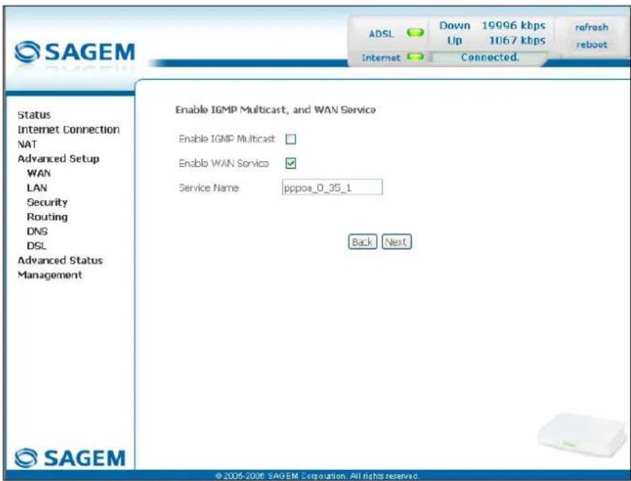
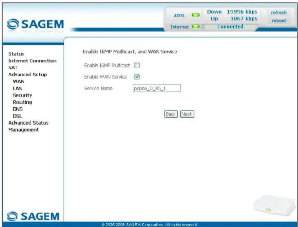
text_image
SAGEM ADSL Down 19996 kbps Up 1067 kbps refresh reboot Internet Connected. Status Internet Connection NAT Advanced Setup WAN LAN Security Routing DNS DSL Advanced Status Management Enable IGMP Multicast, and WAN Service Enable IGMP Multicast □ Enable WAN Service ✓ Service Name pppoa_0_35_1 Back Next © 2006-2006 SAGEM Corporation. All rights reserved.| Field Action Default | ||
| Enable IGMP Multicast | Check the box to activate the IGMP function. | BoxNot checked |
| Enable WAN | Check the box to activate the remote network service (WAN). | Box checked |
| Service | Displays the name of the service being configured. This name, which is allocated automatically, is made up as follows:Protocol_VPI_VCI_IndexFor example: pppoa_0_35_1.Note: You may enter another service name. | pppoa_0_35_1 |
- Click on the Next button to continue configuring the remote network (WAN) in PPPoA mode.
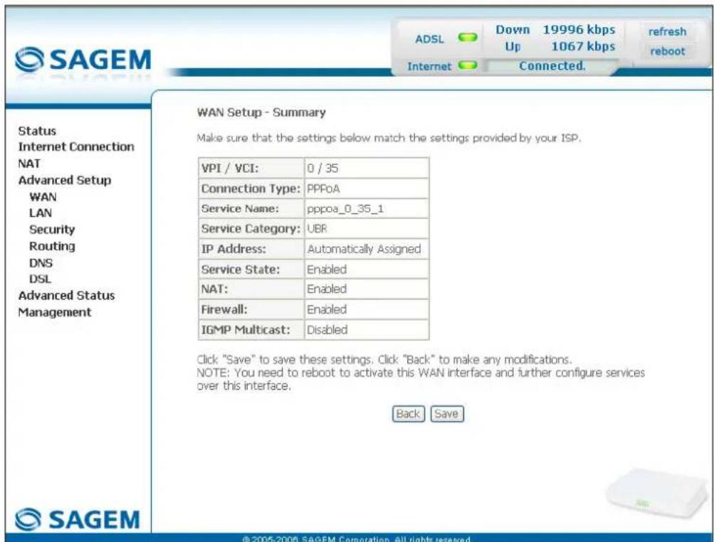
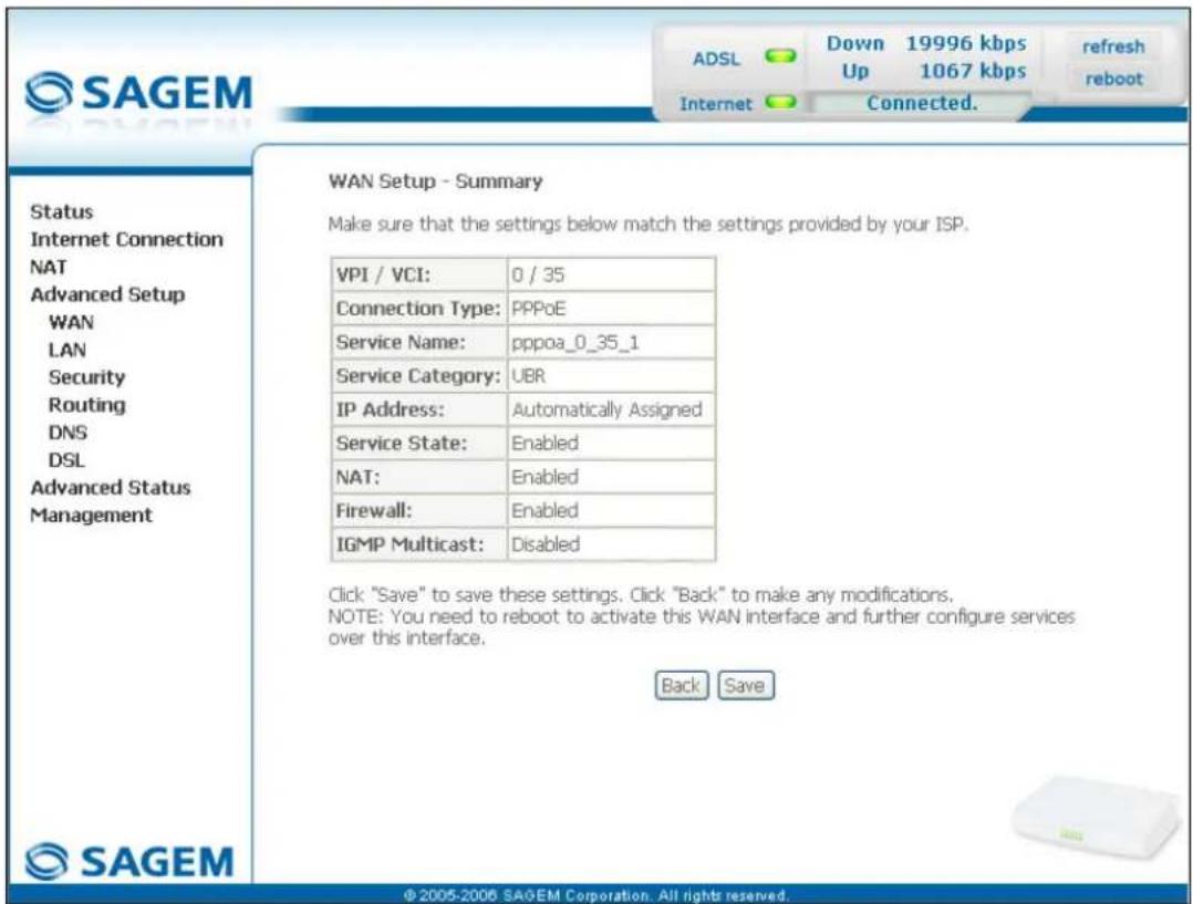
text_image
WAN Setup - Summary Make sure that the settings below match the settings provided by your ISP. VPI / VCI: 0 / 35 Connection Type: PPPoA Service Name: pppoa_0_35_1 Service Category: UBR IP Address: Automatically Assigned Service State: Enabled NAT: Enabled Firewall: Enabled IGMP Multicast: Disabled Back Save © 2005-2006 SAGEM Corporation. All rights reserved.| Field Action | |
| VPI/VCI | Displays the VPI/VCI specific to the "PPPoA" connection |
| Connection Type | Displays the "PPPoA" protocol |
| Service Name | Displays the name of the service: pppoa_0_35_1 |
| Service Category | Displays the type of service adapted to the traffic required. |
| IP Address | Indicates that the IP address is allocated automatically: Automatically Assigned |
| Service State | Displays the status of the service: Enabled |
| NAT | Displays the status of the NAT: Enabled |
| Firewall | Displays the status of the firewall: Enabled |
| IGMP Multicast | Displays the status of the IGMP function: Disabled |
- click on the Save button to save the WAN interface configuration.
PPP over Ethernet (PPPoE)
text_image
SAGEM ADSL Down 19996 kbps refresh Up 1067 kbps reboot Internet Connected. Status Internet Connection NAT Advanced Setup WAN LAN Security Routing DNS DSL Advanced Status Management PPP Username and Password PPP usually requires that you have a user name and password to establish your connection. In the boxes below, enter the user name and password that your ISP has provided to you. PPP Username: login PPP Password: ********** Authentication Method: AUTO □ Dial on demand (with idle timeout timer) □ PPP IP extension □ Use Static IP Address Configure PPP MTU 1492 □ Enable PPP Debug Mode Back Next © 2005-2006 SAGEM Corporation. All rights reserved.| Field Action Default | ||
| PPP Username | Enter your connection ID.This information is provided to you by your Internet Service Provider (ISP). | Empty |
| PPP Password | Enter your connection password.This information is provided to you by your Internet Service Provider (ISP). | Empty |
| PPPoE Service Name | Enter the name of the PPPoE service.This information is provided to you by your Internet Service Provider (ISP). | Empty |
| Authentication Method | Select the authentication method of your choice from the scroll down list:AUTO,PAP,CHAP,MSCHAP. | AUTO |
| Dial on demand (with idle timeout timer) | Check the box to only connect to the Internet on "Traffic". | - |
| Inactivity Timeout (minutes) [1-4320]: ^2 | Enter the inactivity time. This value expressed in minutes is between 1 and 4320 (i.e. 72 hours).If there is no traffic for a certain period of time, the PPPoE session is interrupted. | 0 |
| PPP IP extension | Check the box to allocate your computer the public address obtained from the DHCP server of your Internet Service Provider (ISP). Therefore, your router will act as a bridge between the server and your computer. | - |
| Use Static IP Address | Check the box to use the static IP address. | - |
| IP Address: ^3 | Enter the static IP address. | 0.0.0.0 |
| Configure PPP MTU | Enter an MTU (Maximum Transfer Unit) value. This value, expressed in bytes, is between 38 and 1492 (see Note). | 1492 |
| Enable PPP Debug mode | Check the box to use the PPP Debug mode. In the event of connection failure, this option will enable you to trace a possible problem in the SYSLOG file. | Box Not checked |
Note: The MTU specifies the maximum size of the data used (IP packets) expressed as a number of bytes.
- Click on the Next button to continue configuring the remote network (WAN) in PPPoE mode.
text_image
SAGEM ADSL Down 19996 kbps Up 1067 kbps refresh reboot Internet Connected. Status Internet Connection NAT Advanced Setup WAN LAN Security Routing DNS DSL Advanced Status Management Enable IGMP Multicast, and WAN Service Enable IGMP Multicast Enable WAN Service Service Name pppoa_0_35_1 Back Next © 2006-2006 SAGEM Corporation. All rights reserved.| Field Action Default | ||
| Enable IGMP Multicast | Check the box to activate the IGMP function. | BoxNot checked |
| Enable WAN Service | Check the box to activate the WAN service. | Box checked |
| Service | Displays the name of the service being configured. This name, which is allocated automatically, is made up as follows:Protocol_VPI_VCI_IndexFor example: pppoe_0_35_1.Note: You may enter another service name. | pppoe_0_35_1 |
Click on the Next button to continue configuring the remote network (WAN) in PPPoE mode.
text_image
SAGEM ADSL Down 19996 kbps refresh Up 1067 kbps reboot Internet Connected. Status Internet Connection NAT Advanced Setup WAN LAN Security Routing DNS DSL Advanced Status Management WAN Setup - Summary Make sure that the settings below match the settings provided by your ISP. VPI / VCI: 0 / 35 Connection Type: PPPoE Service Name: pppoa_0_35_1 Service Category: UBR IP Address: Automatically Assigned Service State: Enabled NAT: Enabled Firewall: Enabled IGMP Multicast: Disabled Click "Save" to save these settings. Click "Back" to make any modifications. NOTE: You need to reboot to activate this WAN interface and further configure services over this interface. Back Save © 2005-2006 SAGEM Corporation. All rights reserved.| Field Action | |
| VPI/VCI | Displays the VPI/VCI specific to the "PPPoE" connection |
| Connection Type | Displays the "PPPoE" protocol |
| Service Name | Displays the name of the service: pppoe_0_35_1 |
| Service Category | Displays the type of service adapted to the traffic required. |
| IP Address | Indicates that the IP address is allocated automatically: Automatically Assigned |
| Service State | Displays the status of the service: Enabled |
| NAT | Displays the status of the NAT: Enabled |
| Firewall | Displays the status of the firewall: Enabled |
| IGMP Multicast | Displays the status of the IGMP function: Disabled |
MAC Encapsulation Routing (MER)
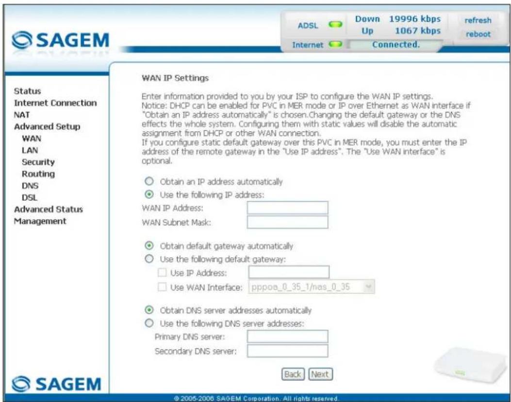
text_image
SAGEM ADSL Down 19996 kbps 1067 kbps refresh reboot Internet Connected. Status Internet Connection NAT Advanced Setup WAN LAN Security Routing DNS DSL Advanced Status Management WAN IP Settings Enter information provided to you by your ISP to configure the WAN IP settings. Notice: DHCP can be enabled for PVC in MER mode or IP over Ethernet as WAN interface if "Obtain an IP address automatically" is chosen. Changing the default gateway or the DNS effects the whole system. Configuring them with static values will disable the automatic assignment from DHCP or other WAN connection. If you configure static default gateway over this PVC in MER mode, you must enter the IP address of the remote gateway in the "Use IP address". The "Use WAN interface" is optional. Obtain an IP address automatically Use the following IP address: WAN IP Address: WAN Subnet Mask: Obtain default gateway automatically Use the following default gateway: Use IP Address: Use WAN Interface: pppo0_0_35_1/nas_0_35 Obtain DNS server addresses automatically Use the following DNS server addresses: Primary DNS server: Secondary DNS server: Back Next © 2005-2006 SAGEM Corporation. All rights reserved.| Field Action Default | ||
| Obtain an IP address automatically | Check the box to obtain an IP address automatically by your router's DHCP server. Note: This box is not checked if a VCC has been created. | Box checked |
| Use the following IP address: | If you check this box, you must enter a static IP address and the dedicated subnet mask. | - |
| WAN IP Address^4 | Enter the static IP address. | 0.0.0.0 |
| WAN Subnet Mask: ^4 | Enter a subnet mask. | 0.0.0.0 |
| Obtain default gateway automatically | Check the box to obtain the gateway IP address automatically by your router's DHCP server. | Box checked |
| Use the following default gateway: | If you check this box, you must enter the default gateway address. | - |
| Use IP Address^5 | Enter the default gateway address. | - |
| Use WAN Interface: ^5 | Select the WAN interface of your choice from the scroll down list (optional) | - |
5 - Information / Configuration
| Field Action Default | ||
| Obtain DNS server addresses automatically | Check the box to obtain DNS server Addresses automatically. | Box checked |
| Use the following DNS server addresses: | If you check this box, you must enter DNS server addresses. | - |
| Primary DNS server^6 | Enter a primary server DNS Address. | - |
| Secondary DNS server^6 | Enter a secondary server DNS Address. | - |
- Click on the Next button to continue configuring the remote network (WAN) in MER mode.
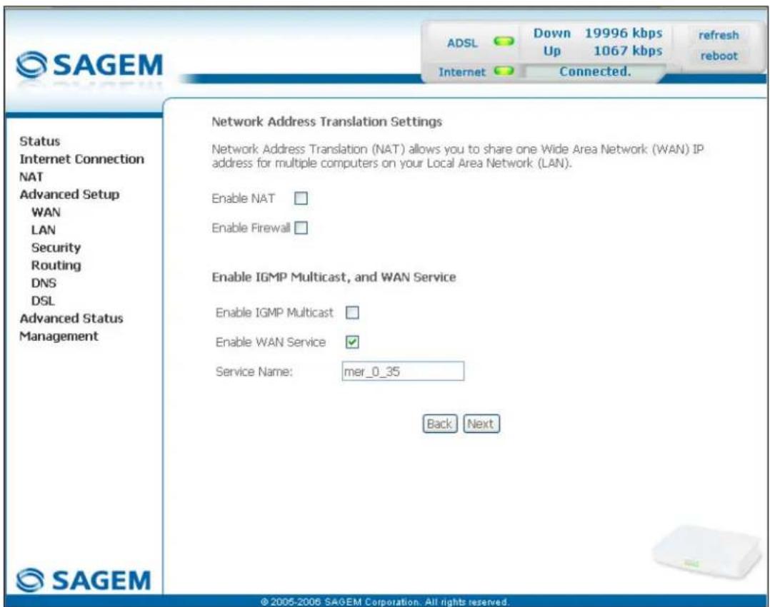
text_image
SAGEM ADSL Down 19996 kbps Up 1067 kbps refresh reboot Internet Connected. Status Internet Connection NAT Advanced Setup WAN LAN Security Routing DNS DSL Advanced Status Management Network Address Translation Settings Network Address Translation (NAT) allows you to share one Wide Area Network (WAN) IP address for multiple computers on your Local Area Network (LAN). Enable NAT □ Enable Firewall □ Enable IGMP Multicast, and WAN Service Enable IGMP Multicast □ Enable WAN Service ✓ Service Name: mer_0_35 Back Next © 2005-2006 SAGEM Corporation. All rights reserved.| Field Action Default | ||
| Enable NAT | Check the box to activate the NAT function. | Box not checked |
| Enable Firewall | Check the box to activate the firewall service. | Box not checked |
| Enable IGMP Multicast | Check the box to activate the IGMP function. | Box not checked |
| Enable WAN Service | Check the box to activate the WAN service. | Box checked |
| Service | Displays the name of the service being configured. This name, which is allocated automatically, is made up as follows:Protocol_VPI_VCI_IndexFor example: mer_0_35_1.Note: You may enter another service name. | mer_0_35_1 |
5 - Information / Configuration
- Click on the Next button to continue configuring the remote network (WAN) in MER mode.
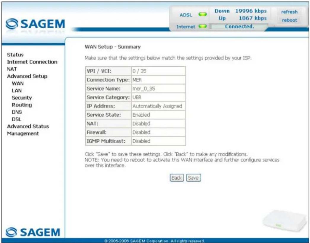
text_image
SAGEM ADSL Down 19996 kbps refresh Up 1067 kbps reboot Internet Connected. Status Internet Connection NAT Advanced Setup WAN LAN Security Routing DNS DSL Advanced Status Management WAN Setup - Summary Make sure that the settings below match the settings provided by your ISP. VPI / VCI: 0 / 35 Connection Type: MER Service Name: mer_0_35 Service Category: UBR IP Address: Automatically Assigned Service State: Enabled NAT: Disabled Firewall: Disabled IGMP Multicast: Disabled Click "Save" to save these settings. Click "Back" to make any modifications. NOTE: You need to reboot to activate this WAN interface and further configure services over this interface. Back Save © 2005-2006 SAGEM Corporation. All rights reserved.| Field Action | |
| VPI/VCI | Displays the VPI/VCI specific to the "MER" connection |
| Connection Type | Displays the "MER" protocol |
| Service Name | Displays the name of the service: mer_0_35_1 |
| Service Category | Displays the type of service adapted to the traffic required. |
| IP Address | Indicates that the IP address is allocated automatically: Automatically Assigned |
| Service State | Displays the status of the service: Enabled |
| NAT | Displays the status of the NAT: Disabled |
| Firewall | Displays the status of the firewall: Disabled |
| IGMP Multicast | Displays the status of the IGMP function: Disabled |
IP over ATM (IPoA)
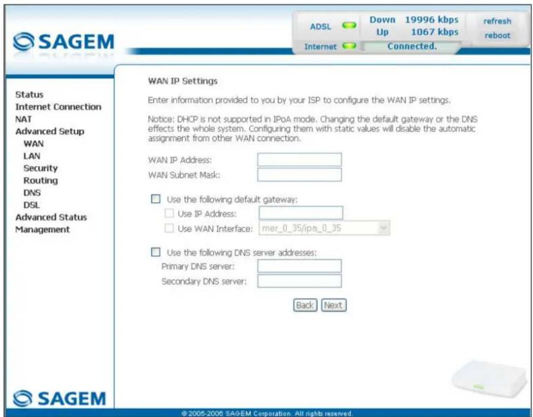
text_image
SAGEM ADSL Down 19996 kbps Up 1067 kbps refresh reboot Internet Connected. Status Internet Connection NAT Advanced Setup WAN LAN Security Routing DNS DSL Advanced Status Management WAN IP Settings Enter information provided to you by your ISP to configure the WAN IP settings. Notice: DHCP is not supported in IPoA mode. Changing the default gateway or the DNS effects the whole system. Configuring them with static values will disable the automatic assignment from other WAN connection. WAN IP Address: WAN Subnet Mask: Use the following default gateway: Use IP Address: Use WAN Interface: mer_0_35/ipa_0_35 Use the following DNS server addresses: Primary DNS server: Secondary DNS server: Back Next © 2005-2006 SAGEM Corporation. All rights reserved.| Field Action Default | ||
| WAN IP Address^4 | Enter the static IP address. | 0.0.0.0 |
| WAN Subnet Mask: ^4 | Enter a subnet mask. | 0.0.0.0 |
| Use the following default gateway: | If you check this box, you must enter a default gateway address. | - |
| Use IP Address^5 | Enter the default gateway address. | - |
| Use WAN Interface: ^5 | Select the WAN interface of your choice from the scroll down list (optional) | - |
| Obtain DNS server addresses automatically | Check the box to obtain DNS server addresses automatically. | Box checked |
| Use the following DNS server addresses: | If you check this box, you must enter DNS server addresses. | - |
| Primary DNS server^6 | Enter a primary server DNS Address. | - |
| Secondary DNS server^6 | Enter a secondary server DNS Address. | - |
5 - Information / Configuration
- Click on the Next button to continue configuring the remote network (WAN) in IPoA mode.
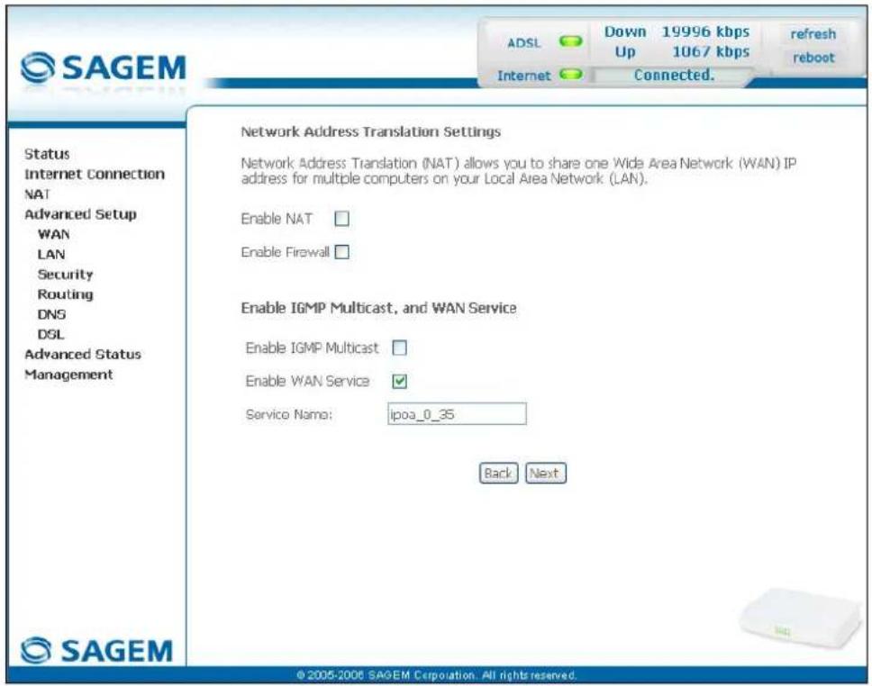
text_image
SAGEM ADSL Down 19996 kbps refresh Up 1067 kbps reboot Internet Connected. Status Internet Connection NAT Advanced Setup WAN LAN Security Routing DNS DSL Advanced Status Management Network Address Translation Settings Network Address Translation (NAT) allows you to share one Wide Area Network (WAN) IP address for multiple computers on your Local Area Network (LAN). Enable NAT □ Enable Firewall □ Enable IGMP Multicast, and WAN Service Enable IGMP Multicast □ Enable WAN Service ✓ Service Name: ipoa_0_35 Back Next © 2005-2006 SAGEM Corporation. All rights reserved.| Field Action Default | ||
| Enable NAT | Check the box to activate the NAT function. | Box not checked |
| Enable Firewall | Check the box to activate the firewall service. | Box not checked |
| Enable IGMP Multicast | Check the box to activate the IGMP function. | Box not checked |
| Enable WAN Service | Check the box to activate the WAN service. | Box checked |
| Service | Displays the name of the service being configured. This name, which is allocated automatically, is made up as follows:Protocol_VPI_VCI_IndexFor example: ipoa_0_35_1.Note: You may enter another service name. | ipoa_0_35_1 |
- Click on the Next button to continue configuring the remote network (WAN) in IPoA mode.
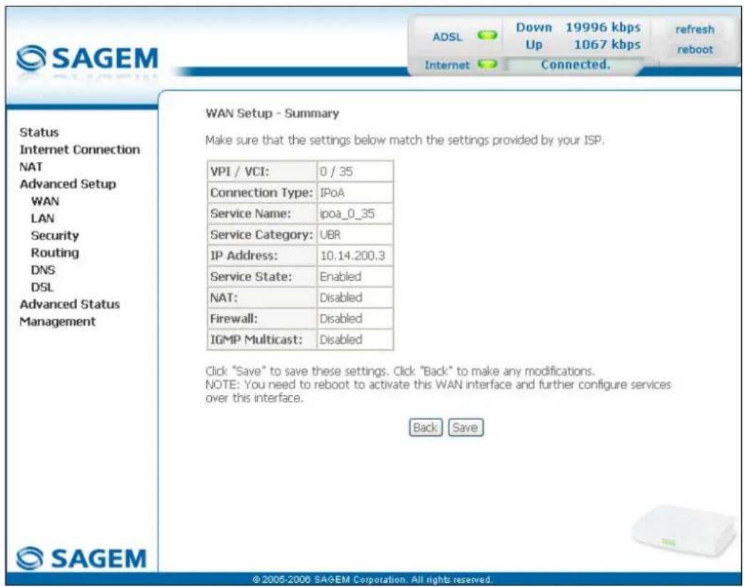
text_image
SAGEM ADSL Down 19996 kbps Up 1067 kbps refresh reboot Internet Connected. Status Internet Connection NAT Advanced Setup WAN LAN Security Routing DNS DSL Advanced Status Management WAN Setup - Summary Make sure that the settings below match the settings provided by your ISP. VPI / VCI: 0 / 35 Connection Type: IPoA Service Name: ipoa_0_35 Service Category: UBR IP Address: 10.14.200.3 Service State: Enabled NAT: Disabled Firewall: Disabled IGMP Multicast: Disabled Click "Save" to save these settings. Click "Back" to make any modifications. NOTE: You need to reboot to activate this WAN interface and further configure services over this interface. Back Save © 2005-2006 SAGEM Corporation. All rights reserved.| Field Action | |
| VPI/VCI | Displays the VPI/VCI specific to the "IPoA" connection |
| Connection Type | Displays the "IPoA" protocol |
| Service Name | Displays the name of the service: ipoa_0_35_1 |
| Service Category | Displays the type of service adapted to the traffic required. |
| IP Address | Displays the IP address entered: 192.168.1.10 |
| Service State | Displays the status of the service: Enabled |
| NAT | Displays the status of the NAT: Disabled |
| Firewall | Displays the status of the firewall: Disabled |
| IGMP Multicast | Displays the status of the IGMP function: Disabled |
Bridging
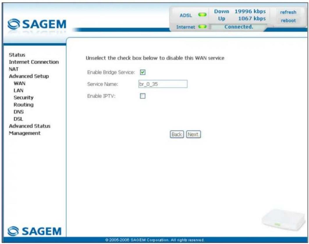
text_image
SAGEM ADSL Down 19996 kbps refresh Up 1067 kbps reboot Internet Connected. Status Internet Connection NAT Advanced Setup WAN LAN Security Routing DNS DSL Advanced Status Management Unselect the check box below to disable this WAN service Enable Bridge Service: ✓ Service Name: br_0_35 Enable IPTV: Back Next © 2005-2006 SAGEM Corporation. All rights reserved.| Field Action Default | ||
| Enable Bridge service | Check the box to activate the "Bridge" service. | Box checked |
| Service Name | Displays the name of the service being configured. This name, which is allocated automatically, is made up as follows:Protocol_VPI_VCI_Index.For example: br_8_35_1.Note: You may enter another service name. | - |
| Enable IPTV | Check the box to be able to enter another IP address of the external network of the "Set Top Box" connected virtually to this "PVC". | Box not checked |
| IPTV Name | This field only appears if the Enable IPTV box in the previous field is checked.Enter the IP address of the external network of the "Set Top Box" connected virtually to this "PVC". | - |
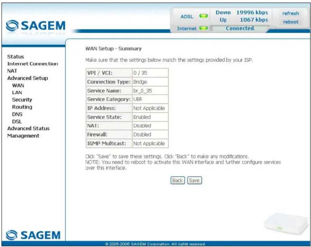
text_image
SAGEM Status Internet Connection NAT Advanced Setup WAN LAN Security Routing DNS DSL Advanced Status Management WAN Setup - Summary Make sure that the settings below match the settings provided by your ISP. VPI / VCI: 0 / 35 Connection Type: Bridge Service Name: br_0_35 Service Category: UBR IP Address: Not Applicable Service State: Enabled NAT: Disabled Firewall: Disabled IGMP Multicast: Not Applicable Click "Save" to save these settings. Click "Back" to make any modifications. NOTE: You need to reboot to activate this WAN interface and further configure services over this interface. Back Save © 2005-2006 SAGEM Corporation. All rights reserved.| Field Action | |
| VPI/VCI | Displays the VPI/VCI specific to the "Bridge" connection |
| Connection Type | Displays the "Bridge" protocol |
| Service Name | Displays the name of the service: br_0_35_1 |
| Service Category | Displays the type of service adapted to the traffic required |
| IP Address | In the "Bridge" connection, this field is: Not Applicable |
| Service State | Displays the status of the service: Enabled |
| NAT | Displays the status of the NAT: Disabled |
| Firewall | Displays the status of the firewall: Disabled |
| IGMP Multicast | In the "Bridge" connection, this field is: Not Applicable |
- click on the Save button to save the WAN interface configuration.
5.8.2 LAN
Object: This is used to configure the IP parameters for the local network (LAN).
- Select the LAN menu in the Advanced Setup section to display the following screen:
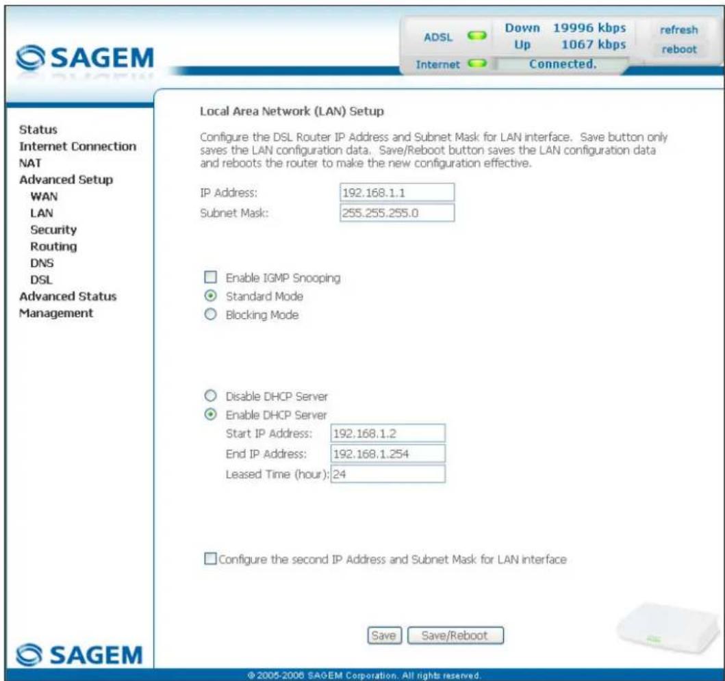
text_image
SAGEM ADSL Down 19996 kbps Up 1067 kbps Internet Connected. Refresh reboot Status Internet Connection NAT Advanced Setup WAN LAN Security Routing DNS DSL Advanced Status Management Local Area Network (LAN) Setup Configure the DSL Router IP Address and Subnet Mask for LAN interface. Save button only saves the LAN configuration data. Save/Reboot button saves the LAN configuration data and reboots the router to make the new configuration effective. IP Address: 192.168.1.1 Subnet Mask: 255.255.255.0 Enable IGMP Snooping Standard Mode Blocking Mode Disable DHCP Server Enable DHCP Server Start IP Address: 192.168.1.2 End IP Address: 192.168.1.254 Leased Time (hour): 24 Configure the second IP Address and Subnet Mask for LAN interface Save Save/Reboot © 2005-2006 SAGEM Corporation. All rights reserved.| Field Action Default | ||
| IP Address | Enter the address of your local network | 192.168.1.1 |
| Subnet Mask | Enter your network's subnet mask. | 255.255.255.0 |
| Enable IGMP Snooping | Check this box to activate the IGMP (Internet Group Management Protocol) protocol. This lets you manage the declarations of belonging to one or more groups with Multicast routers. | Box not checked |
| Field Action Default | ||
| Standard Mode | Check the box if you wish the IGMP snooping runs in normal mode (transparency with IGMP frames). | Box checked |
| Blocking Mode | Check the box if you wish the IGMP snooping runs in blocking mode (interception and removal of IGMP frames). | Box not checked |
| Disable DHCP | Check the box to not activate your router's DHCP server.Note: You must configure your computer with the parameters appropriate to your local network (IP address, subnet mask and default gateway) as well as enter the primary and secondary DNS server addresses. | Box not checked |
| Enable DHCP | Check the box to activate your router's DHCP server.Note: You must configure your computer as DHCP client and DNS client (or enter the primary and secondary DNS server addresses). | Box checked |
| Start IP Address | Enter the first address attributed by your router's DHCP server. | 192.168.1.2 |
| End IP Address ^7 | Enter the last address attributed by your router's DHCP server. | 192.168.1.254 |
| Lease Time (hour) ^7 | Enter an unavailability time for each address attributed expressed in hours. | 24 |
| Configure the second IP Address and Subnet Mask for LAN interface | Check the box to configure the IP parameters (IP address, subnet mask) of a second address for the local network (LAN). | Box not checked |
| IP Address ^8 | Enter a second address for your local network (LAN). | - |
| Subnet Mask ^8 | Enter a subnet mask for the second address for your local network (LAN). | - |
5.8.3 Security
This menu contains 2 sub-menus:
- Outgoing (cf. § 5.8.3.1),
- Incoming (cf. § 5.8.3.2).
5.8.3.1 Outgoing
Object: This menu is used to create outgoing IP filters to refuse data from the LAN to the WAN and list the existing outgoing IP filters.
By default, all the outgoing data is accepted.
- Select the Outgoing sub-menu in the Security menu in the Advanced Setup section to display the following screen:
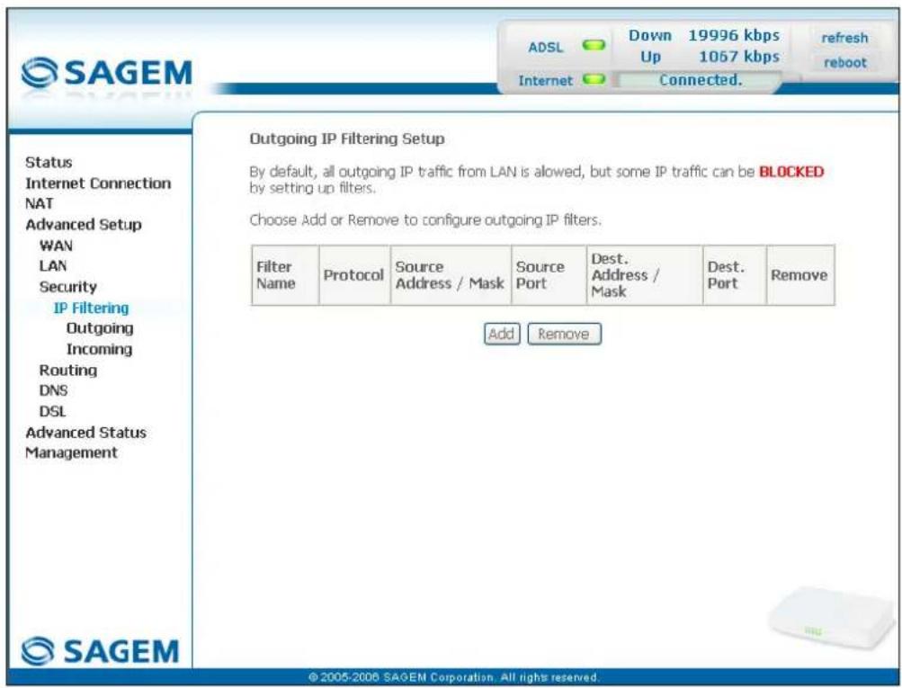
text_image
Outgoing IP Filtering Setup By default, all outgoing IP traffic from LAN is allowed, but some IP traffic can be BLOCKED by setting up filters. Choose Add or Remove to configure outgoing IP filters. Filter Name Protocol Source Address / Mask Source Port Dest. Address / Mask Dest. Port Remove Add Remove © 2005-2008 SAGEM Corporation. All rights reserved.| Field Meaning | |
| Filter Name | Name of the filter. |
| Protocol | Transport protocol. |
| Source Address / Mask | Source IP address / Subnet mask. |
| Source Port | Source port |
| Dest. Address / Mask | Destination IP address / Subnet mask. |
| Dest. Port | Destination port. |
Add
- Click on the Add button to display the following screen:
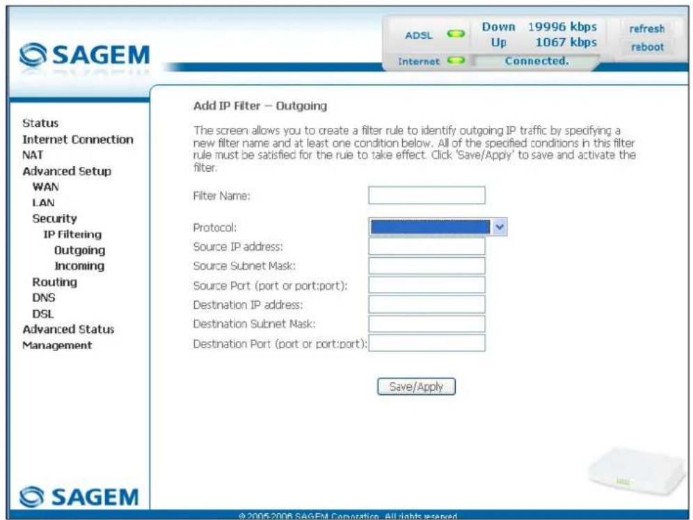
text_image
SAGEM ADSL Down 19996 kbps Up 1067 kbps refresh reboot Internet Connected. Add IP Filter – Outgoing The screen allows you to create a filter rule to identify outgoing IP traffic by specifying a new filter name and at least one condition below. All of the specified conditions in this filter rule must be satisfied for the rule to take effect. Click 'Save/Apply' to save and activate the filter. Filter Name: Protocol: Source IP address: Source Subnet Mask: Source Port (port or port:port): Destination IP address: Destination Subnet Mask: Destination Port (port or port:port): Save/Apply Status Internet Connection NAT Advanced Setup WAN LAN Security IP Filtering Outgoing Incoming Routing DNS DSL Advanced Status Management SAGEM| Field Action | |
| Filter Name | Enter a representative name for the filter. |
| Protocol | Select the dedicated protocol from the scroll down list (TCP/UDP, TCP, UDP, ICMP). |
| Source IP Address | Enter the Source IP address (LAN). |
| Source Subnet Mask | Subnet mask. |
| Source Port (port or port:port) | Enter a "Source" port (LAN) or range of ports.Note: For one port, for example, enter 80.For a range of ports, enter 80:90. |
| Dest. IP Address | Enter the Destination IP address (WAN). |
| Dest. Subnet Mask | Subnet mask. |
| Dest. Port (port or port:port) | Enter a "destination" port (WAN) or range of ports.Note: For one port, for example, enter 80.For a range of ports, enter 80:90. |
5.8.3.2 Incoming
Object: This menu is used to create incoming IP filters to refuse data from the WAN to the LAN and list the existing incoming IP filters.
By default, all the incoming data is refused when the Firewall is activated.
- Select the Incoming sub-menu in the Security menu in the Advanced Setup section to display the following screen:
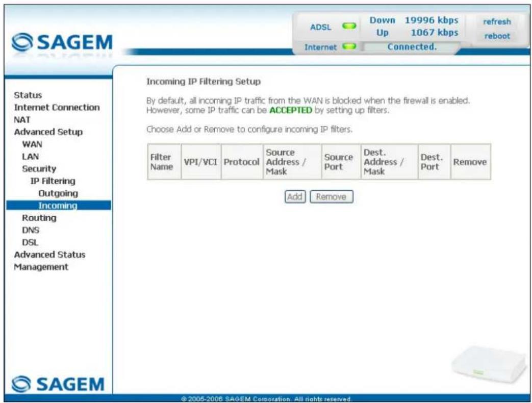
text_image
SAGEM ADSL Down 19996 kbps Up 1067 kbps refresh reboot Internet Connected. Incoming IP Filtering Setup By default, all incoming IP traffic from the WAN is blocked when the firewall is enabled. However, some IP traffic can be ACCEPTED by setting up filters. Choose Add or Remove to configure incoming IP filters. Filter Name VPI/VCI Protocol Somcure Address / Mask Source Port Dest. Address / Mask Dest. Port Remove Add Remove Status Internet Connection NAT Advanced Setup WAN LAN Security IP Filtering Outgoing Incoming Routing DNS DSL Advanced Status Management SAGEM © 2005-2006 SAGEM Corporation. All rights reserved.Add
- Click on the Add button to display the following screen:
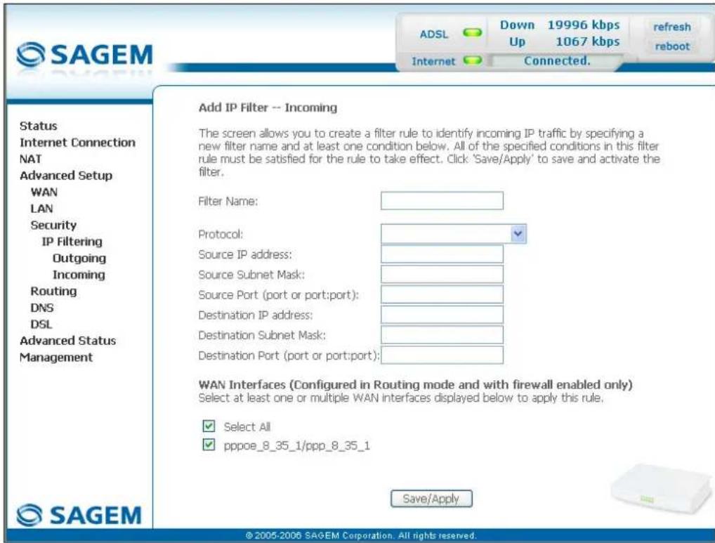
text_image
SAGEM ADSL Down 19996 kbps Up 1067 kbps refresh reboot Internet Connected. Status Internet Connection NAT Advanced Setup WAN LAN Security IP Filtering Outgoing Incoming Routing DNS DSL Advanced Status Management Add IP Filter -- Incoming The screen allows you to create a filter rule to identify incoming IP traffic by specifying a new filter name and at least one condition below. All of the specified conditions in this filter rule must be satisfied for the rule to take effect. Click 'Save/Apply' to save and activate the filter. Filter Name: Protocol: Source IP address: Source Subnet Mask: Source Port (port or port:port): Destination IP address: Destination Subnet Mask: Destination Port (port or port:port): WAN Interfaces (Configured in Routing mode and with firewall enabled only) Select at least one or multiple WAN interfaces displayed below to apply this rule. ✓ Select All ✓ pppoe_8_35_1/ppp_8_35_1 Save/Apply © 2005-2006 SAGEM Corporation. All rights reserved.| Field Action | |
| Filter Name | Enter a representative name for the filter. |
| Protocol | Select the dedicated protocol from the scroll down list (TCP/UDP, TCP, UDP, ICMP). |
| Source IP Address | Enter the Source IP address (WAN). |
| Source Subnet Mask | Subnet mask. |
| Source Port (port or port:port) | Enter a "Source" port (WAN) or range of ports.Note: For one port, for example, enter 80.For a range of ports, enter 80:90. |
| Dest. IP Address | Enter the destination IP address (LAN). |
| Dest. Subnet Mask | Subnet mask. |
| Dest. Port (port or port:port) | Enter a "destination" port (LAN) or range of ports.Note: For one port, for example, enter 80.For a range of ports, enter 80:90. |
WAN interfaces
| Field Action Default | ||
| Select all | Check the box to select all WAN interfaces.Note: Checking out the box, you do not select any interface and you also check out the pppoe_8_35_1/ ppp_8_35_1 box. | Box checked |
| pppoe_8_35_1/ ppp_8_35_1 | Check the box to select the displayed interface. | Box checked |
5.8.4 Routing
This menu contains two sub-menus:
- Default Gateway (cf. § 5.8.4.1),
• Static Route (cf. § 5.8.4.2).
5.8.4.1 Default Gateway
Object: This menu is used either to allocate dynamically a default gateway address to the router from a PVC or to enter an address or choose an interface.
- Select the Default Gateway sub-menu in the Routing menu in the Advanced Setup section to display the following screen:
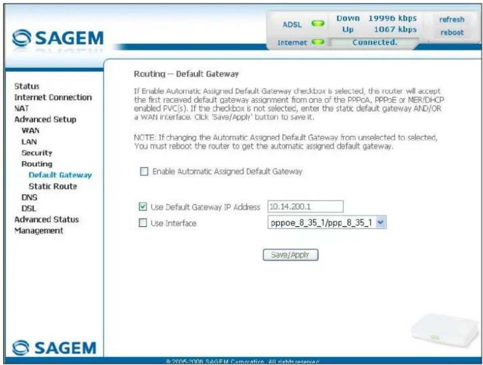
text_image
SAGEM ADSL Down 19996 kbps 1067 kbps refresh reboot Internet Connected. Status Internet Connection NAT Advanced Setup WAN LAN Security Routing Default Gateway Static Route DNS DSL Advanced Status Management Routing -- Default Gateway If Enable Automatic Assigned Default Gateway checkbox is selected, this router will accept the first received default gateway assignment from one of the PPPoA, PPPoE or MER/DHCP enabled PVC(s). If the checkbox is not selected, enter the static default gateway AND/OR a WAN interface. Click 'Save/Apply' button to save it. NOTE: If changing the Automatic Assigned Default Gateway from unselected to selected, You must reboot the router to get the automatic assigned default gateway. Enable Automatic Assigned Default Gateway Use Default Gateway IP Address 10.14.200.1 Use Interface pppoe_8_35_1/ppp_8_35_1 Save/Apply © 2005-2006 SAGEM Camoration - All rights reserved.| Field Action Default | ||
| EnableAutomatic Assigned Default Gateway | Check the box to allocate automatically a default gateway for your router. | Box checked |
| Use Default Gateway IP Address9 | Check the box to use a default address. | Box checked empty |
| Use Interface9 | Check the box then select the interface you want to use from the scroll down list (pppoe_8_35_1 for example). | Box not checked Interface used |
5.8.4.2 Static Route
Object: This menu is used to add a static route.
- Select the Static Route sub-menu in the Routing menu in the Advanced Setup section to display the following screen:
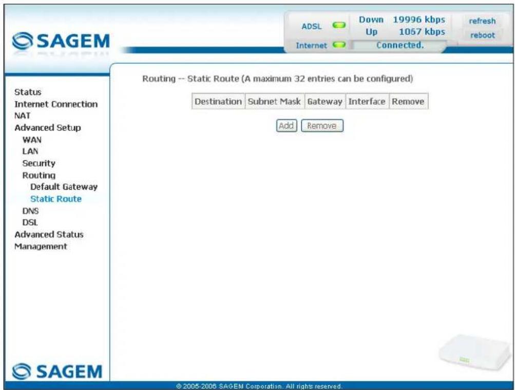
text_image
SAGEM ADSL Down 19996 kbps Up 1057 kbps refresh reboot Internet Connected. Status Internet Connection NAT Advanced Setup WAN LAN Security Routing Default Gateway Static Route DNS DSL Advanced Status Management Routing -- Static Route (A maximum 32 entries can be configured) Destination Subnet Mask Gateway Interface Remove Add Remove © 2005-2006 SAGEM Corporation. All rights reserved.| Field Meaning | |
| Destination | Remote network IP address |
| Subnet Mask | Remote subnet mask |
| Gateway | Default gateway of the remote network |
| Interface | Remote network interface |
Add
- Click on the Add button to display the following screen:
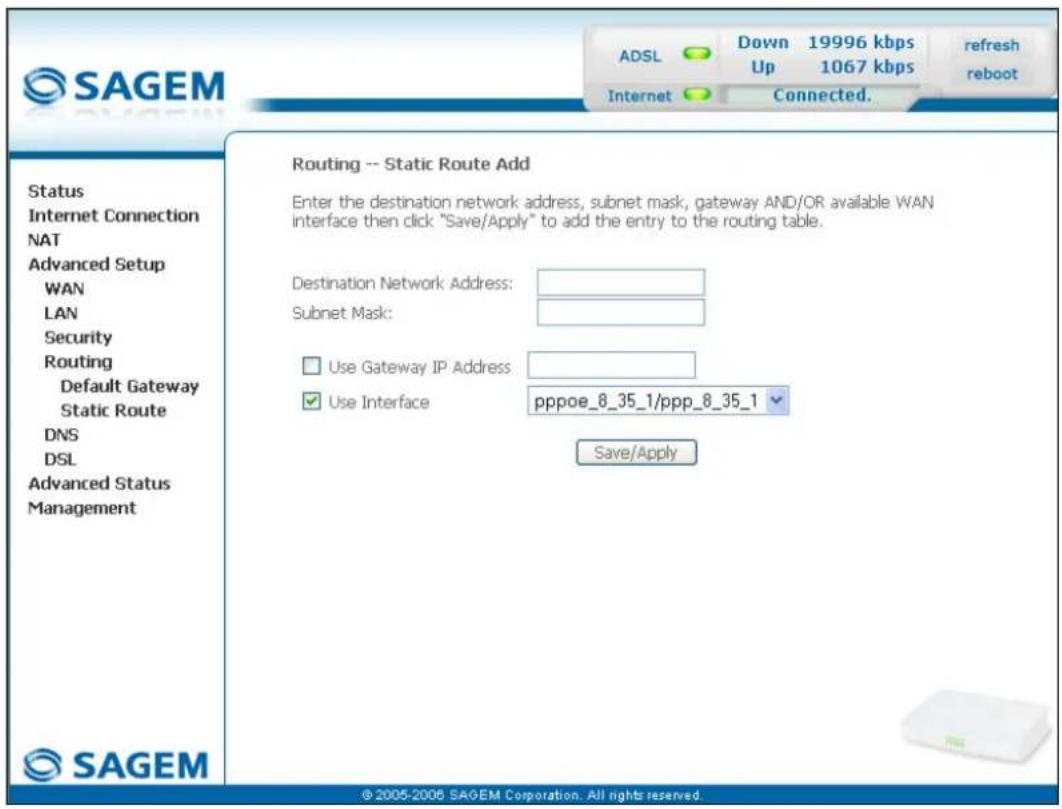
text_image
SAGEM ADSL Down 19996 kbps Up 1067 kbps refresh reboot Internet Connected. Routing -- Static Route Add Enter the destination network address, subnet mask, gateway AND/OR available WAN interface then click "Save/Apply" to add the entry to the routing table. Destination Network Address: Subnet Mask: Use Gateway IP Address: Use Interface pppoe_8_35_1/ppp_8_35_1 Save/Apply Status Internet Connection NAT Advanced Setup WAN LAN Security Routing Default Gateway Static Route DNS DSL Advanced Status Management © 2005-2006 SAGEM Corporation. All rights reserved.| Field Action Default | ||
| Destination Network Address | Enter the IP address of the remote network. | Empty |
| Subnet Mask | Enter the remote subnet mask. | Empty |
| Use Gateway IP Address | Check the appropriate box then enter the IP address of the gateway. | Box not checked Empty |
| Use Interface | Select the interface you want to use from the scroll down list (pppoe_8_35_1 for example). | Box checked Interface used |
5.8.5 DNS
Object: This menu enables the automatic resolution of domain names by polling remote servers.
- Select the DNS menu in the Advanced Setup section to display the following screen:
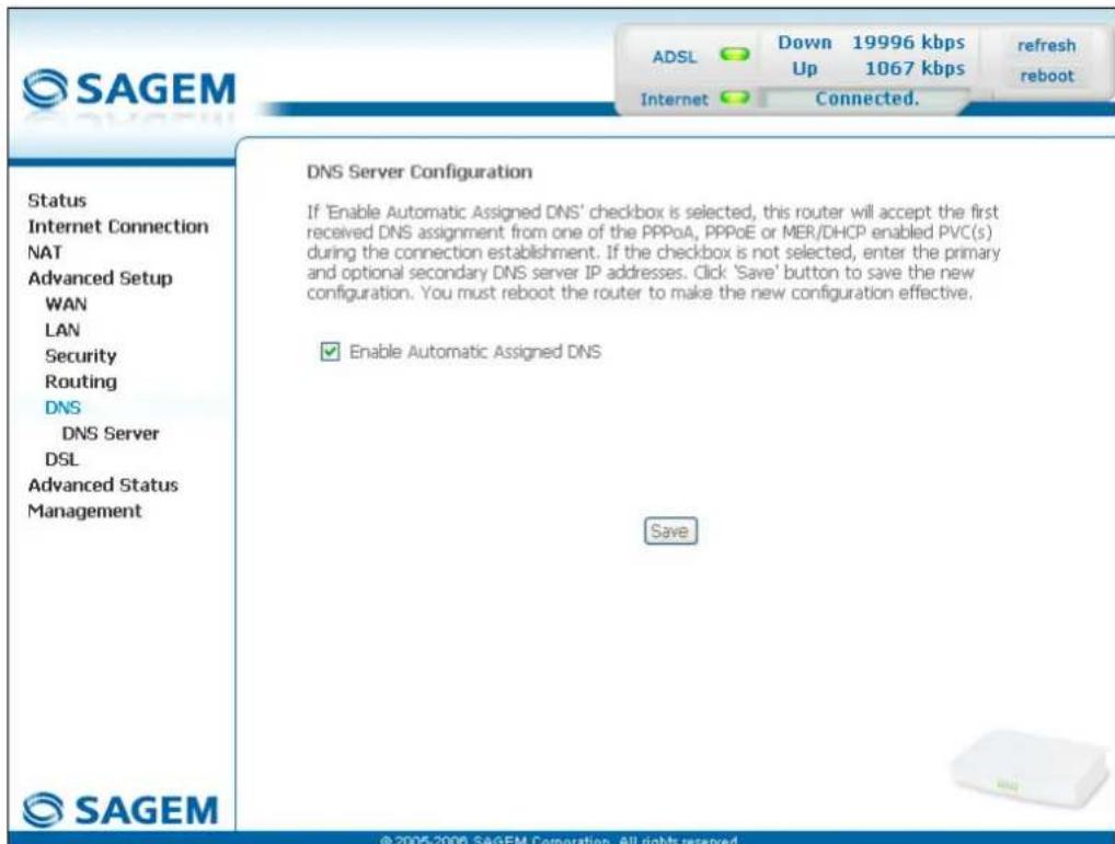
text_image
SAGEM ADSL Down 19996 kbps Up 1067 kbps Internet Connected. Refresh reboot Status Internet Connection NAT Advanced Setup WAN LAN Security Routing DNS DNS Server DSL Advanced Status Management DNS Server Configuration If 'Enable Automatic Assigned DNS' checkbox is selected, this router will accept the first received DNS assignment from one of the PPPoA, PPPoE or MER/DHCP enabled PVC(s) during the connection establishment. If the checkbox is not selected, enter the primary and optional secondary DNS server IP addresses. Click 'Save' button to save the new configuration. You must reboot the router to make the new configuration effective. ✓ Enable Automatic Assigned DNS Save © 2005-2006 SAGEM Corporation. All rights reserved.| Field Action Default | ||
| Enable Automatic Assigned DNS | Check the appropriate box to allocate a domain name address. | Box checked |
| Primary DNS server ^10 | Enter a primary DNS server address. | - |
| Secondary DNS server ^10 | Enter a secondary DNS server address. | - |
5.8.6 DSL
Object: The purpose of this menu is to parameter your ADSL line.
- Select the DSL menu in the Advanced Setup section to display the following screen:
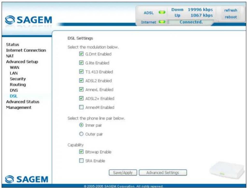
text_image
SAGEM ADSL Down 19996 kbps Up 1067 kbps refresh reboot Internet Connected. Status Internet Connection NAT Advanced Setup WAN LAN Security Routing DNS DSL Advanced Status Management DSL Settings Select the modulation below. ✓ G.Dmt Enabled ✓ G.lte Enabled ✓ T1.413 Enabled ✓ ADSL2 Enabled ✓ AnnexL Enabled ✓ ADSL2+ Enabled ✓ AnnexM Enabled Select the phone line pair below. ● Inner pair ○ Outer pair Capability ✓ Bitswap Enable □ SRA Enable Save/Apply Advanced Settings ©2005-2008 SAGEM Corporation. All rights reserved.Modulation
| Field Default | |
| G.Dmt Enabled Box checked | |
| G.lite Enabled Box checked | |
| T1.413 Enabled Box checked | |
| ADSL2 Enabled Box checked | |
| AnnexL Enabled Box checked | |
| ADSL2+ Enabled Box checked | |
| AnnexM Enabled Box not checked | |
Check the boxes according to the characteristics of your line.
Phone line pair
| Field Default | |
| Inner pair Selected | box |
| Outer pair Box not | selected |
Capability
| Field Default | |
| Bitswap Enable Box checked | |
| SRA Enable Box not checked | |
- Click on the Advanced Settings button to display the following screen:
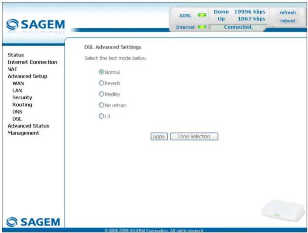
text_image
SAGEM ADSL Down 19996 kbps Up 1067 kbps refresh reboot Internet Connected. Status Internet Connection NAT Advanced Setup WAN LAN Security Routing DNS DSL Advanced Status Management DSL Advanced Settings Select the test mode below. Normal Reverb Medley No retrain L3 Apply Tone Selection ©2005-2006 SAGEM Corporation. All rights reserved| Field Default | |
| Normal Selected box | |
| Reverb Box not selected | |
| Medley Box not selected | |
| No retrain Box not selected | |
| L3 Box not selected | |
- Click on the Tone Selection button to display the following screen:
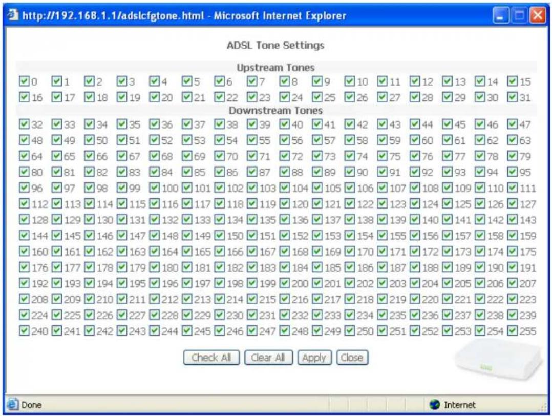
text_image
http://192.168.1.1/adslcfgtone.html - Microsoft Internet Explorer ADSL Tone Settings Upstream Tones ✓ 0 ✓ 1 ✓ 2 ✓ 3 ✓ 4 ✓ 5 ✓ 6 ✓ 7 ✓ 8 ✓ 9 ✓ 10 ✓ 11 ✓ 12 ✓ 13 ✓ 14 ✓ 15 ✓ 16 ✓ 17 ✓ 18 ✓ 19 ✓ 20 ✓ 21 ✓ 22 ✓ 23 ✓ 24 ✓ 25 ✓ 26 ✓ 27 ✓ 28 ✓ 29 ✓ 30 ✓ 31 Downstream Tones ✓ 32 ✓ 33 ✓ 34 ✓ 35 ✓ 36 ✓ 37 ✓ 38 ✓ 39 ✓ 40 ✓ 41 ✓ 42 ✓ 43 ✓ 44 ✓ 45 ✓ 46 ✓ 47 ✓ 48 ✓ 49 ✓ 50 ✓ 51 ✓ 52 ✓ 53 ✓ 54 ✓ 55 ✓ 56 ✓ 57 ✓ 58 ✓ 59 ✓ 60 ✓ 61 ✓ 62 ✓ 63 ✓ 64 ✓ 65 ✓ 66 ✓ 67 ✓ 68 ✓ 69 ✓ 70 ✓ 71 ✓ 72 ✓ 73 ✓ 74 ✓ 75 ✓ 76 ✓ 77 ✓ 78 ✓ 79 ✓ 80 ✓ 81 ✓ 82 ✓ 83 ✓ 84 ✓ 85 ✓ 86 ✓ 87 ✓ 88 ✓ 89 ✓ 90 ✓ 91 ✓ 92 ✓ 93 ✓ 94 ✓ 95 ✓ 96 ✓ 97 ✓ 98 ✓ 99 ✓ 100 ✓ 101 ✓ 102 ✓ 103 ✓ 104 ✓ 105 ✓ 106 ✓ 107 ✓ 108 ✓ 109 ✓ 110 ✓ 111 ✓ 112 ✓ 113 ✓ 114 ✓ 115 ✓ 116 ✓ 117 ✓ 118 ✓ 119 ✓ 120 ✓ 121 ✓ 122 ✓ 123 ✓ 124 ✓ 125 ✓ 126 ✓ 127 ✓ 128 ✓ 129 ✓ 130 ✓ 131 ✓ 132 ✓ 133 ✓ 134 ✓ 135 ✓ 136 ✓ 137 ✓ 138 ✓ 139 ✓ 140 ✓ 141 ✓ 142 ✓ 143 ✓ 144 ✓ 145 ✓ 146 ✓ 147 ✓ 148✓✓✓✓✓✓✓✓✓✓✓✓✓✓✓✓✓✓✓✓✓✓✓✓✓✓✓✓✓✓✓✓✓✓✓✓✓✓✓✓✓✓✓✓✓✓✓✓✓✓✓✓✓✓✓✓✓✓✓✓✓✓✓✓✓✓✓✓✓✓✓✓✓✓✓✓✓✓✓✓✓✓✓✓✓✓✓✓✓✓✓✓✓✓✓✓✓✓✓✓# ✓ 160 ✓ 161 ✓ 162 ✓ 163 ✓Check All Clear All Apply Close
Done InternetNote: There are 32 ascending tones and 224 descending tones.
- Click on the Check All button to select all the tones or the Clear All button to select none of them.

All the tones are selected by default.
To select a tone, simply check the associated box.
To not select a tone, simply leave its associated box empty.
5.9 Advanced Status
Object: This heading is used to display the status of your router.
This section contains the following cinq menus:
- WAN (cf. § 5.9.1),
• Statistics (cf. § 5.9.2), - Route (cf. § 5.9.3),
- ARP (cf. § 5.9.4),
- DHCP (cf. § 5.9.5).
5.9.1 WAN
Object: This menu is used to display all the parameters which concern the remote network.
- Select the WAN menu in the Advanced Status section to display the following screen:
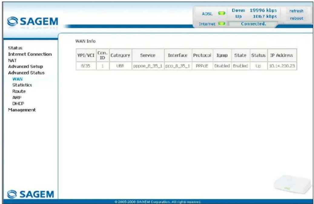
text_image
SAGEM ADSL Down 19996 kbps Up 10167 kbps Internet Connected. refresh reboot Status Internet Connection NAT Advanced Setup Advanced Status WAN Statistics Route ARP DHCP Management WAN Info YPI/VCI Con. ID Category Service Interface Protocol Igmp State Status IP Address 8/35 1 UBR pppoe_8_35_1 poo_8_35_1 PPoE Disabled Enabled Up 10.14.200.23 © 2005-2006 SAGEM Corporation. All rights reserved.5.9.2 Statistics
Object: This menu is used to display all the router's statistics.
This menu contains the following four sub menus:
• LAN (cf. § 5.9.2.1),
- WAN (cf. § 5.9.2.2),
- ATM (cf. § 5.9.2.3),
- ADSL (cf. § 5.9.2.4).
5.9.2.1 LAN
Object: This menu is used to display all the parameters which concern the local network (LAN).
- Select the LAN sub menu in the Statistics menu in the Advanced Status section to display the following screen:
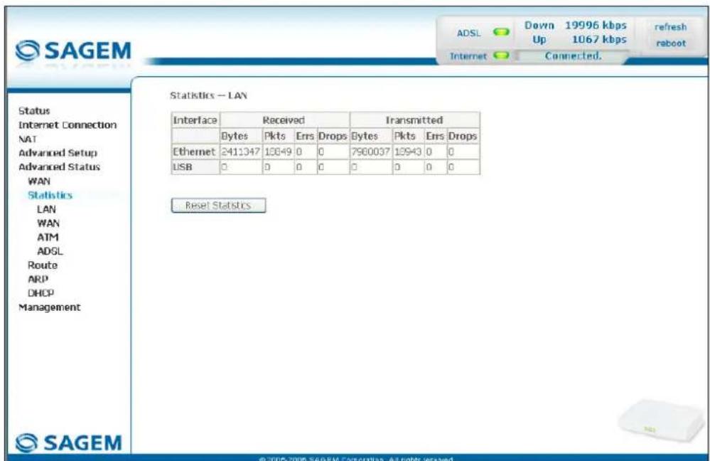
text_image
SAGEM ADSL Down 19996 kbps Up 1067 kbps Internet Connected. Refresh reboot Status Internet Connection NAT Advanced Setup Advanced Status WAN Statistics LAN WAN ATM ADSL Route ARP DHCP Management Statistics - LAN Interface Received Transmitted Bytes Pkts Errs Drops Bytes Pkts Errs Drops Ethernet 2411347 13049 0 0 7960037 13943 0 0 USB 0 0 0 0 0 0 0 0 Reset Statistics © 2005-2008 SAGEM Corporation. All rights reserved.5.9.2.2 WAN
Object: This menu is used to display all the parameters which concern the remote network (WAN).
- Select the WAN sub menu in the Statistics menu in the Advanced Status section to display the following screen:
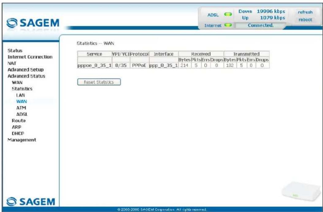
text_image
SAGEM Status Internet Connection NAT Advanced Setup Advanced Status WAN Statistics LAN WAN ATM ADSL Route ARP DHCP Management SAGEM Statistics -- WAN Service VP1/VCIProtocol Interface Received Transmitted Bytes Pkts Errs Drops Bytes Pkts Errs Drops pppoe_0_35_1 0/35 PPPoE ppp_0_35_1 214 5 0 0 182 5 0 0 Reset Statistics © 2005-2006 SAGEM Corporation. All rights reserved.5.9.2.3 ATM
Object: This menu is used to display all the ATM statistics of the line.
- Select the ATM sub menu in the Statistics menu in the Advanced Status section to display the following screen:
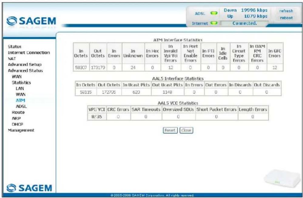
text_image
SAGEM Status Internet Connection NAT Advanced Setup Advanced Status WAN Statistics LAN WAN ATM ADSL Route ARP DHCP Management SAGEM ATM Interface Statistics In Octets Out Octets In Errors In Unknown In Hoc Errors In Invalid Vpi Vci Errors In Port Not Enable Errors In PTI Errors In Idle Cells In Circuit Type Errors In DAM RM CRC Errors In GFC Errors 58307 173179 0 24 0 12 0 0 0 0 0 12 AAL5 Interface Statistics In Octets Out Octets In Ucast Pkts Out Ucast Pkts In Errors Out Errors In Discards Out Discards 58115 172705 620 1148 0 0 0 0 AAL5 VCC Statistics VPI/ VCI CRC Errors SAR Timeouts Diversized SDUs Short Packet Errors Length Errors 8/35 0 0 0 0 0 Reset Close ©2005-2006 SAGEM Corporation. All rights reserved.5.9.2.4 ADSL
Object: This menu is used to display all the ADSL statistics of the line.
- Select the ADSL sub menu in the Statistics menu in the Advanced Status section to display the following screen:
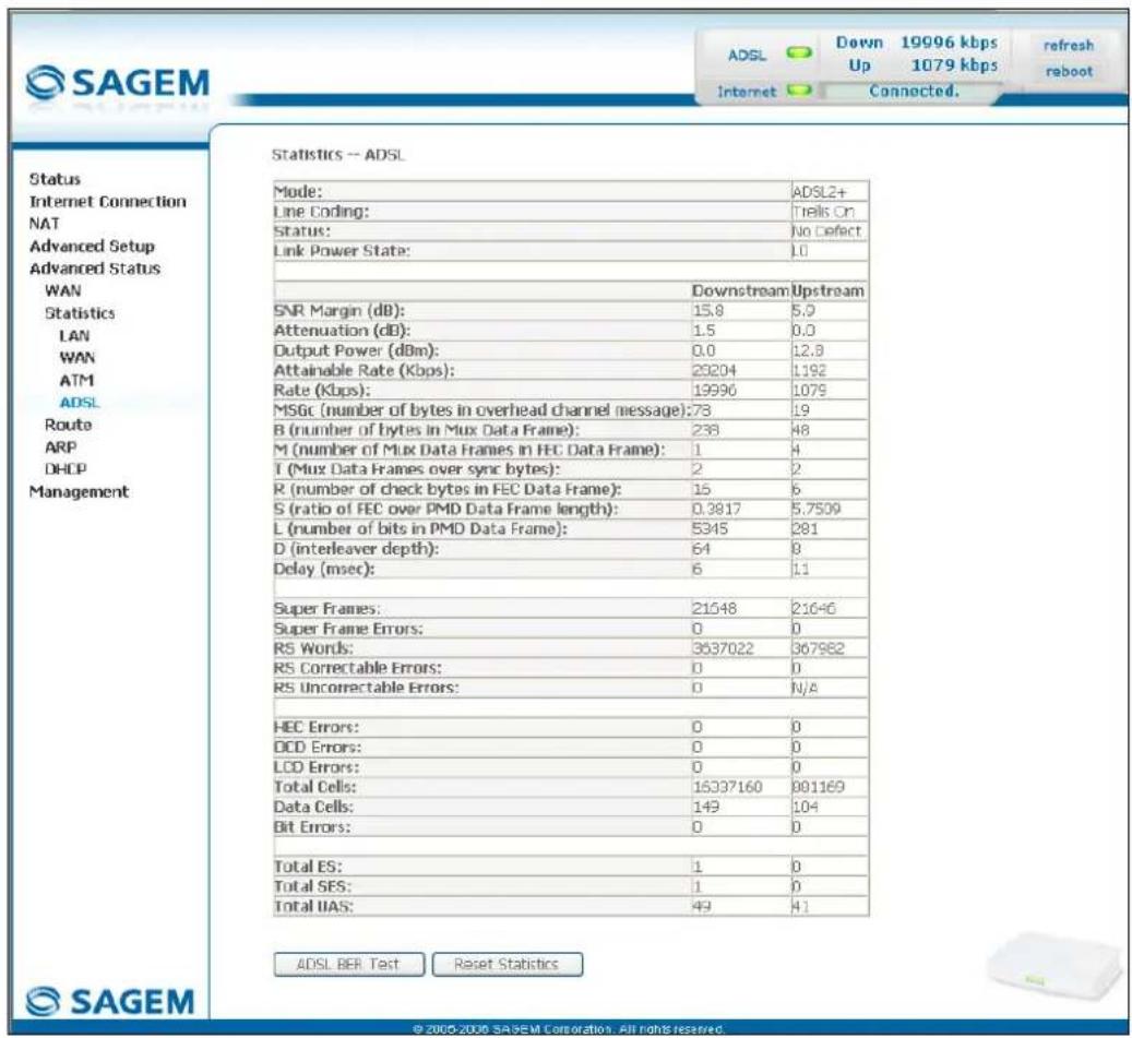
text_image
SAGEM Internet Down 19996 kbps Up 1079 kbps Connected. Refresh rboot Status Internet Connection NAT Advanced Setup Advanced Status WAN Statistics LAN WAN ATM ADSL Route ARP DHCP Management Statistics -- ADSL Mode: Line Coding: Status: Link Power State: Downstream Upstream SNR Margin (dB): Attenuation (dB): Output Power (dBm): Attainable Rate (Kbps): Rate (Kbps): MSGc (number of bytes in overhead channel message): B (number of bytes in Mux Data Frame): M (number of Mux Data Frames in FEC Data Frame): T (Mux Data Frames over sync bytes): R (number of check bytes in FEC Data Frame): S (ratio of FEC over PMD Data Frame length): L (number of bits in PMD Data Frame): D (interleaver depth): Delay (msec): Super Frames: Super Frame Errors: RS Words: RS Correctable Errors: RS Uncorrectable Errors: HEC Errors: OCD Errors: LCD Errors: Total Cells: Data Cells: Bit Errors: Total ES: Total SES: Total UAS: ADSL BER Test Reset Statistics © 2000-2006 SAGEM Corporation. All rights reserved.5.9.3 Route
Object: This menu is used to display all the information concerning your router's routing.
- Select the Route menu in the Advanced Status section to display the following screen:
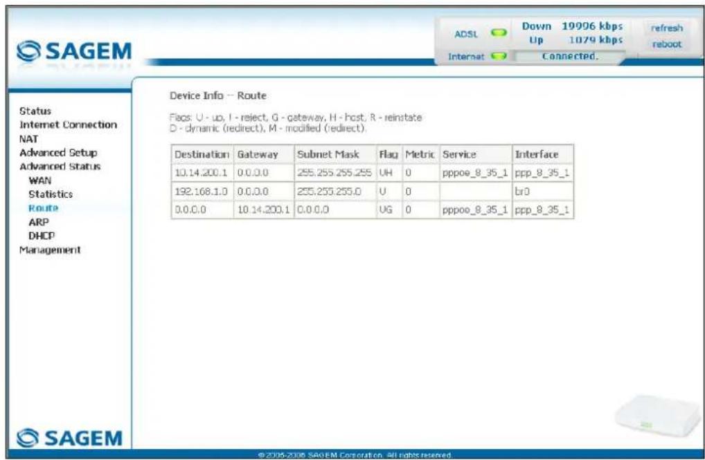
text_image
SAGEM ADSL Down 19996 kbps Up 1079 kbps Refresh reboot Internet Connected. Device Info -- Route Status Internet Connection NAT Advanced Setup Advanced Status WAN Statistics Route ARP DHCP Management Destination Gateway Subnet Mask Flag Metric Service Interface 10.14.200.1 0.0.0.0 255.255.255.255 UH 0 pppoe_8_35_1 ppp_8_35_1 192.168.1.0 0.0.0.0 255.255.255.0 U 0 br0 0.0.0.0 10.14.200.1 0.0.0.0 UG 0 pppoe_8_35_1 ppp_8_35_1 ©2006-2006 SAGEM Corporation. All rights reserved.5.9.4 ARP
Object: This menu is used to display all the information concerning address resolution (ARP: Address Resolution Protocol). This lets you find out the physical address of a computer's network card, corresponding to an IP address.
- Select the ARP menu in the Advanced Status section to display the following screen:
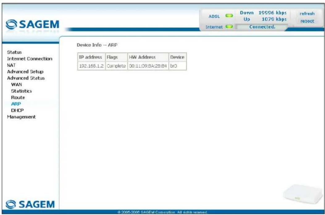
text_image
SAGEM ADSL Down 19006 kbps Up 1070 kbps Internet Connected. Refresh reboot Status Internet Connection NAT Advanced Setup Advanced Status WAN Statistics Route ARP DHCP Management Device Info -- ARP IP address Flags WHW Address Device 192.168.1.2 Complete 00:11:09:8A:28:84 bro © 2005-2006 SAGEM Corporation - All rights reserved.5.9.5 DHCP
Object: This menu is used to display all the computers which obtained an IP address from the router's DHCP server.
- Select the DHCP menu in the Advanced Status section to display the following screen:
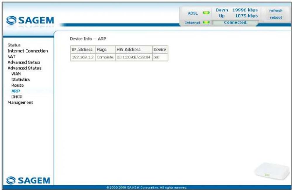
text_image
SAGEM ADSL Down 19996 kbps Up 1079 kbps Internet Connected. refresh reboot Status Internet Connection NAT Advanced Setup Advanced Status WAN Statistics Route ARP DHCP Management Device Info — ARP IP address Flags WH Address Device 192:168.1.2 Complete DC:11:09:BA:28:84 briD ©2005-2006 SAGEM Corporation, All rights reserved.5.10 Management
Object: This menu lets you manage your router.
This section contains the following five menus:
- Settings (cf. § 5.10.1),
• System Log (cf. § 5.10.2), - Access Control (cf. § 5.10.3),
- Update Software (cf. § 5.10.4),
- Save/Reboot (cf. § 5.10.5).
5.10.1 Settings
This menu contains the following three sub menus:
- Backup (cf. § 5.10.1.1),
- Update (cf. § 5.10.1.2),
- Restore Default (cf. § 5.10.1.3).
5.10.1.1 Backup
Object: This menu is used to backup the current configuration to a file with a .conf extension.

It is recommended to save the current configuration on your computer to a file
- Select the Backup sub menu in the Settings menu of the Management section to display the following screen:
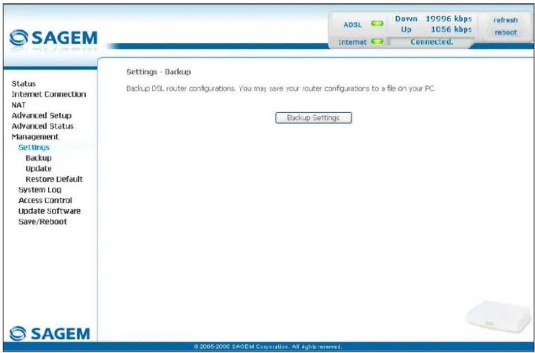
text_image
SAGEM ADSL Down 19996 kbps Up 1056 kbps refresh reboot Internet Connected. Status Internet Connection NAT Advanced Setup Advanced Status Management Settings Backup Update Restore Default System Log Access Control Update Software Save/Reboot Settings - Backup Backup DSL router configurations. You may save your router configurations to a file on your PC. Backup Settings SAGEM © 2005-2006 SAQEM Corporation. All rights reserved.5 - Information / Configuration
- Click on the Backup Settings button; the following screen appears:
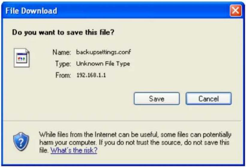
text_image
File Download Do you want to save this file? Name: backupsettings.conf Type: Unknown File Type From: 192.168.1.1 Save Cancel While files from the Internet can be useful, some files can potentially harm your computer. If you do not trust the source, do not save this file. What's the risk?- Click on the Save button to save the current configuration file, for example, on your computer.
- Select the directory where you want to save the "backupsettings.conf" configuration file.

The process takes a few seconds.
5.10.1.2 Update
Object: This menu enables the router to recover a configuration which has already been saved to a file with a .conf extension.
- Select the Update sub menu in the Settings menu of the Management section to display the following screen:
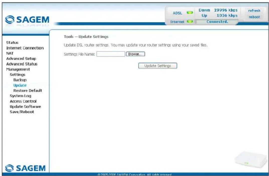
text_image
SAGEM ADSL Down 19996 kbps Up 1056 kbps refresh reboot Internet Connected. Tools -- Update Settings Update DSL router settings. You may update your router settings using your saved files. Settings File Name: Browse... Update Settings Status Internet Connection NAT Advanced Setup Advanced Status Management Settings Backup Update Restore Default System Log Access Control Update Software Save/Reboot SAGEM ©2006-2006 SAGEM Corporation. All rights reserved.Proceed as follows for your router configurer to display a configuration which has already been saved:
- Enter the path then the name of the configuration file,
or - Click on the Browse button and select the path then the configuration file,
- Select the configuration file then click on the Update Settings button to recover a configuration which has already been saved.

The process takes around 2 minutes.
5.10.1.3 Restore Default
Object: This menu is used to return to factory configuration.

The existing configuration is completely overwritten.
- Select the Restore Default sub menu in the Settings menu of the Management section to display the following screen:
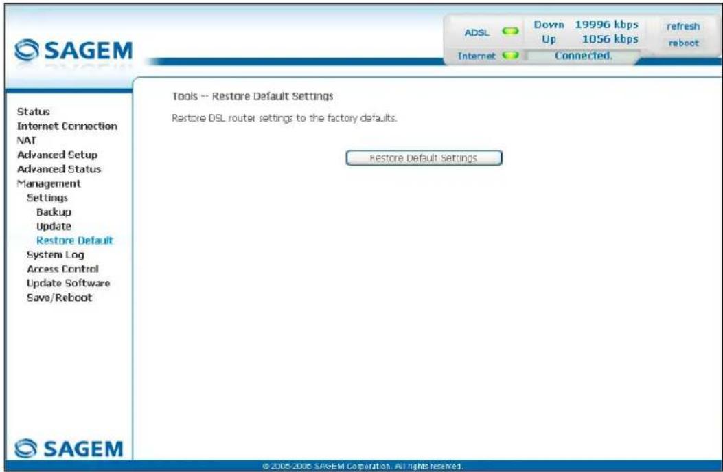
text_image
SAGEM Status Internet Connection NAT Advanced Setup Advanced Status Management Settings Backup Update Restore Default System Log Access Control Update Software Save/Reboot SAGEM Tools -- Restore Default Settings Restore DSL router settings to the factory defaults. Restore Default Settings ADSL Down 19996 kbps Up 1056 kbps refresh reboot Internet Connected. © 2005-2006 SAGEM Corporation. All rights reserved.- Select the configuration file then click on the Restore Default Settings button and the following screen appears:
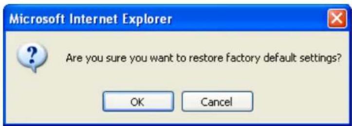
text_image
Microsoft Internet Explorer Are you sure you want to restore factory default settings? OK Cancel- Click on the OK button if you really want to return to the factory configuration.
A few moments after, the screen of the "Internet Connection" menu appears. To refer to paragraph 5.6.

The process takes around 2 minutes.
5.10.2 System Log
Object: This menu is used to view and/or configure the events which occur on your router.
- Select the System Log menu in the Management section to display the following screen:
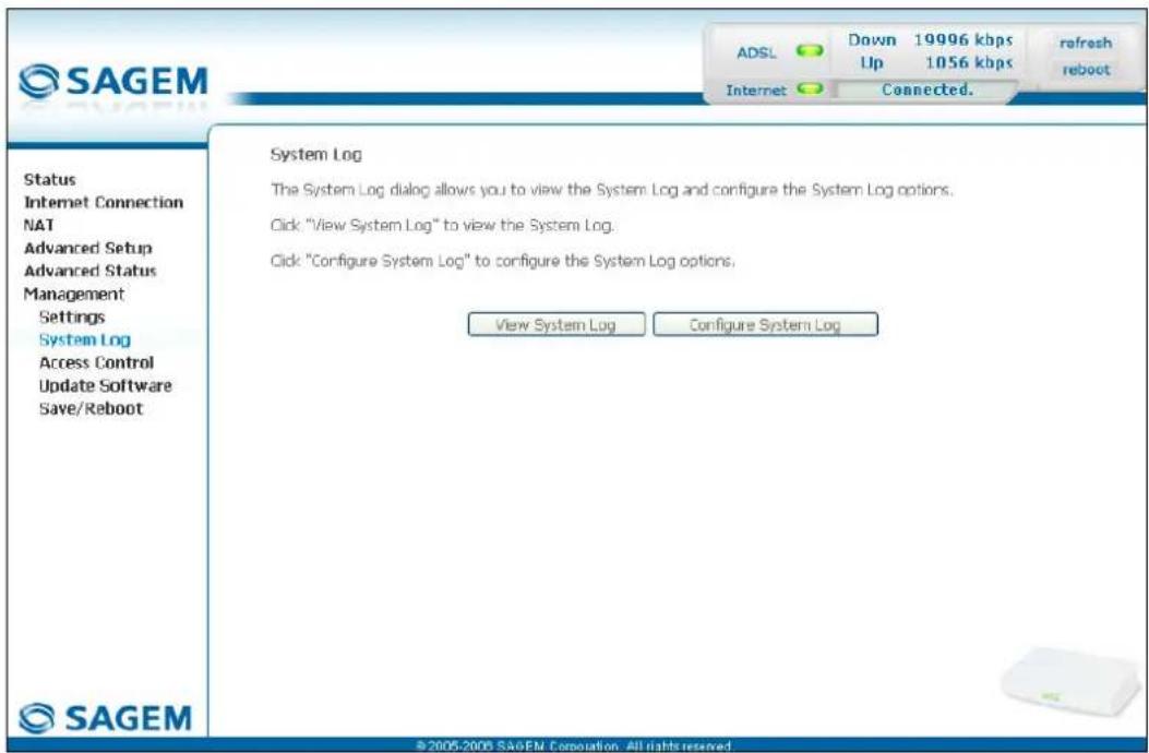
text_image
SAGEM ADSL Down 19996 kbps Up 1056 kbps Internet Connected. Refresh reboot Status Internet Connection NAT Advanced Setup Advanced Status Management Settings System Log Access Control Update Software Save/Reboot System Log The System Log dialog allows you to view the System Log and configure the System Log options. Click "View System Log" to view the System Log. Click "Configure System Log" to configure the System Log options. View System Log Configure System Log ©2005-2006 SAGEM Corporation. All rights reserved.View System Log
- Click on the View System Log button to display the events with the severity you configured (see table in the next paragraph - "Configure System Log").
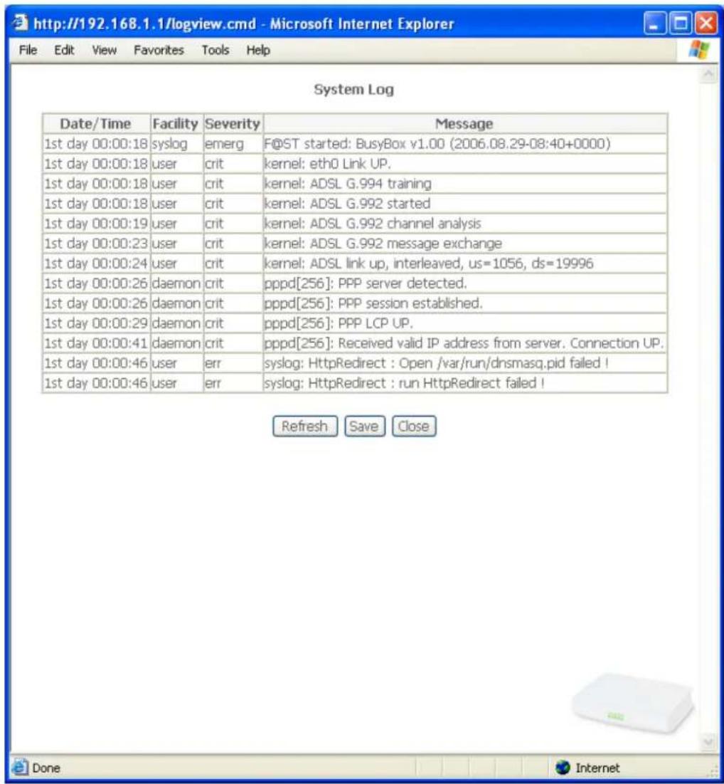
text_image
Date/Time Facility Severity Message 1st day 00:00:18 syslog emerg F@ST started: BusyBox v1.00 (2006.08.29-08:40+0000) 1st day 00:00:18 user crit kernel: eth0 Link UP. 1st day 00:00:18 user crit kernel: ADSL G.994 training 1st day 00:00:18 user crit kernel: ADSL G.992 started 1st day 00:00:19 user crit kernel: ADSL G.992 channel analysis 1st day 00:00:23 user crit kernel: ADSL G.992 message exchange 1st day 00:00:24 user crit kernel: ADSL link up, interleaved, us=1056, ds=19996 1st day 00:00:26 daemon crit pppd[256]: PPP server detected. 1st day 00:00:26 daemon crit pppd[256]: PPP session established. 1st day 00:00:29 daemon crit pppd[256]: PPP LCP UP. 1st day 00:00:41 daemon crit pppd[256]: Received valid IP address from server. Connection UP. 1st day 00:00:46 user err syslog: HttpRedirect : Open /var/run/dnsmasq.pid failed ! 1st day 00:00:46 user err syslog: HttpRedirect : run HttpRedirect failed ! Refresh Save Close- Click on the Save button to save all the events allocated to the severity you configured.
Configure System Log
- Click on the Configure System Log button to configure the events which occur on your router.
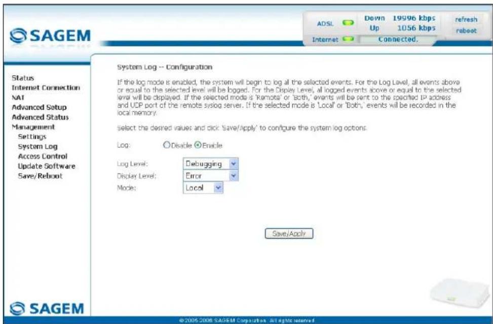
text_image
SAGEM ADSL Down 19996 kbps refresh Up 1056 kbps reboot Internet Connected. Status Internet Connection NAT Advanced Setup Advanced Status Management Settings System Log Access Control Update Software Save/Reboot System Log -- Configuration If the log mode is enabled, the system will begin to log all the selected events. For the Log Level, all events above or equal to the selected level will be logged. For the Display Level, all logged events above or equal to the selected level will be displayed. If the selected mode is 'Remote' or 'Both,' events will be sent to the specified IP address and UDP port of the remote syslog server. If the selected mode is 'Local' or 'Both,' events will be recorded in the local memory. Select the desired values and click 'Save/Apply' to configure the system log options. Log: Disable Enable Log Level: Debugging Display Level: Error Mode: Local Save/Apply ©2005-2006 SAGEM Corporation All rights reserved| Field Action Default | ||
| Log | Select Enable to activate the saving of all the events to a log and display on screen or Disable to deactivate. | Enable |
| Log Level | Select the appropriate severity from the scroll down list. All the events with this severity, or a higher severity, will be saved to your router's volatile "flash" memory.The severities are classified in decreasing order of importance.Emergency,Alert,Critical,Error,Notice,Informational,Debugging. | Debugging |
| Display Level | Select the appropriate severity from the scroll down list. All the events with this severity, or a higher severity, can be viewed by pressing the "View System Log" button.The severities are classified in decreasing order of importance.Emergency,Alert,Critical,Error,Notice,Informational,Debugging. | Error |
| Mode | Select the destination ID from the scroll down list:Local: All the events are returned to your router via a "Buffer" memory.Remote: All the events are returned to the "Syslog" server.Both : Both modes. | Local |
| Server IP Address ^11 | Enter the IP address of the "Syslog" address on which all the events will be saved. | 0.0.0.0 |
| Server UDP Port ^11 | Enter the number of the port associated with the "Syslog" server. | 514 |
5.10.3 Access Control
This menu contains the following three sub menus:
• Services (cf. § 5.10.3.1),
• IP Address (cf. § 5.10.3.2),
- Passwords (cf. § 5.10.3.3).
5.10.3.1 Services
Object: this sub menu is used to activate or deactivate Services such as FTP, FTPP etc.
- Select the Services sub menu in the Access Control menu of the Management section to display the following screen:
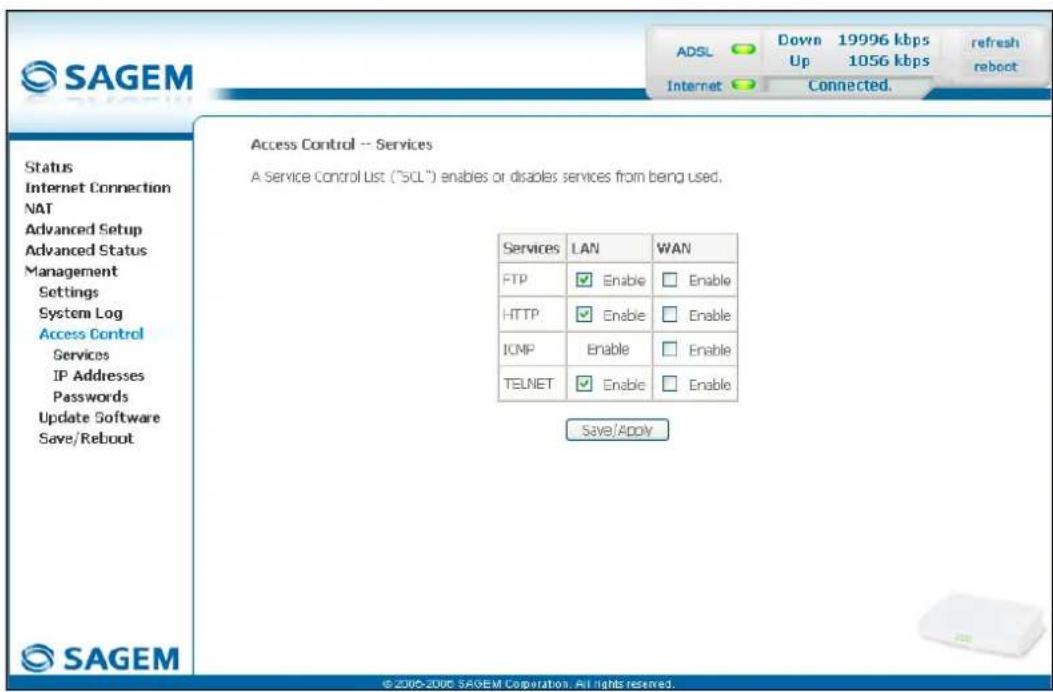
text_image
SAGEM ADSL Down 19996 kbps Up 1056 kbps refresh reboot Internet Connected. Access Control -- Services A Service Control List ("SQL") enables or disables services from being used. Status Internet Connection NAT Advanced Setup Advanced Status Management Settings System Log Access Control Services IP Addresses Passwords Update Software Save/Reboot Services LAN WAN FTP Enable Enable HTTP Enable Enable ICMP Enable Enable TELNET Enable Enable Save/Apply ©2006-2006 SAGEM Corporation. All rights reserved.The table displayed in the screen above indicates that the services listed such as FTP, HTTP, ICMP, SSH and TELNET are all activated ("Enable" box checked) on the local network (LAN) and deactivated ("Enable" box not checked) on the remote network (WAN).
Check the Enable box to activate the selected service on the local network (LAN) or on the remote network (WAN).
Note: The ICMP service is always activated on the local network (LAN) and may be activated or deactivated on the remote network (WAN).
5.10.3.2 IP Address
- Select the IP Address sub menu in the Access Control menu of the Management section to display the following screen:
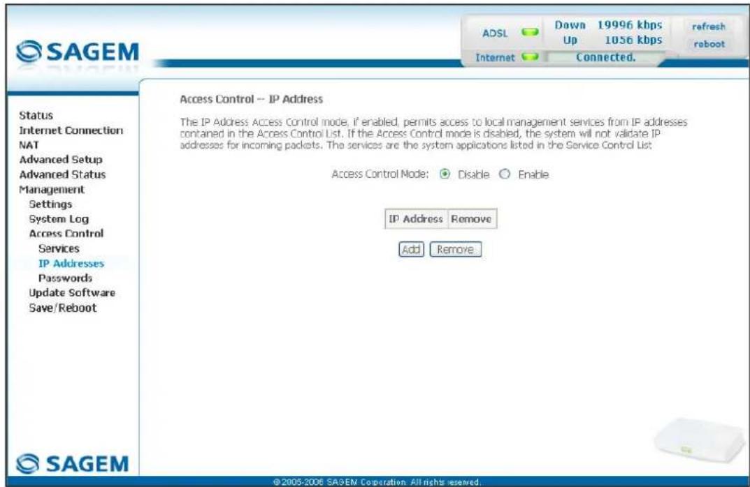
text_image
SAGEM ADSL Down 19996 kbps Up 1056 kbps refresh reboot Internet Connected. Access Control -- IP Address The IP Address Access Control mode, if enabled, permits access to local management services from IP addresses contained in the Access Control List. If the Access Control mode is disabled, the system will not validate IP addresses for incoming packets. The services are the system applications listed in the Service Control List. Access Control Mode: Disable Enable IP Address Remove Add Remove ©2005-2006 SAGEM Corporation. All rights reserved.| Field Action Default | ||
| Access Control Mode | Select Enable to activate the access control mode or Disable to not activate it. | Box not checked |
Add
Click on the Add button to add an IP address.
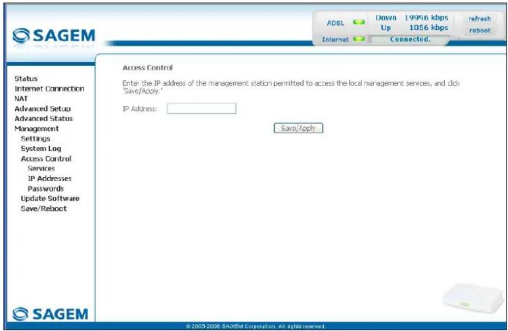
text_image
SAGEM ADSL Down 19996 kbps 1056 kbps refresh reboot Internet Connected. Access Control Enter the IP address of the management station permitted to access the local management services, and click "Save/Apply." IP Address: Save/Apply Status Internet Connection NAT Advanced Setup Advanced Status Management Settings System Log Access Control Services IP Addresses Passwords Update Software Save/Reboot SAGEM © 2005-2006 SAGEM Corporation. All rights reserved.Note: From this address you may access the local management services when the access control is active.
5.10.3.3 Passwords
- Select the Passwords sub menu in the Access Control menu of the Management section to display the following screen:
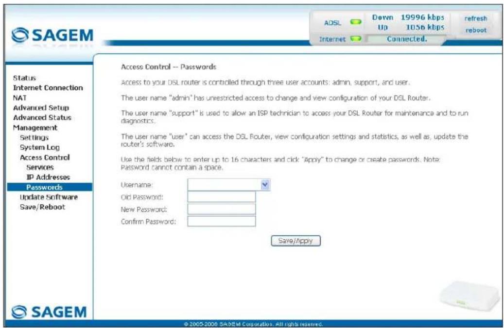
text_image
SAGEM ADSL Down 19996 kbps 1056 kbps refresh reboot Internet Connected. Access Control -- Passwords Access to your DSL router is controlled through three user accounts: admin, support, and user. The user name "admin" has unrestricted access to change and view configuration of your DSL Router. The user name "support" is used to allow an ISP technician to access your DSL Router for maintenance and to run diagnostics. The user name "user" can access the DSL Router, view configuration settings and statistics, as well as, update the router's software. Use the fields below to enter up to 16 characters and click "Apply" to change or create passwords. Note: Password cannot contain a space. Username: Old Password: New Password: Confirm Password: Save/Apply Status Internet Connection NAT Advanced Setup Advanced Status Management Settings System Log Access Control Services IP Addresses Passwords Update Software Save/Reboot © 2000-2000 SAGEM Corporation. All rights reserved.| Field Action | |
| User Name | Select a user name from the scroll down list:Admin,Support,User.Note: This list has been established in increasing order of restriction. |
| Old Password | Enter your old password |
| New Password | Enter your new password |
| Confirm Password | Confirm your new password |
Note: The password is a string of a maximum of 16 alphanumeric characters.
5.10.4 Update Software
Object: This menu lets you update the latest version of the router software.
- Select the Update Software menu in the Management section to display the following screen:
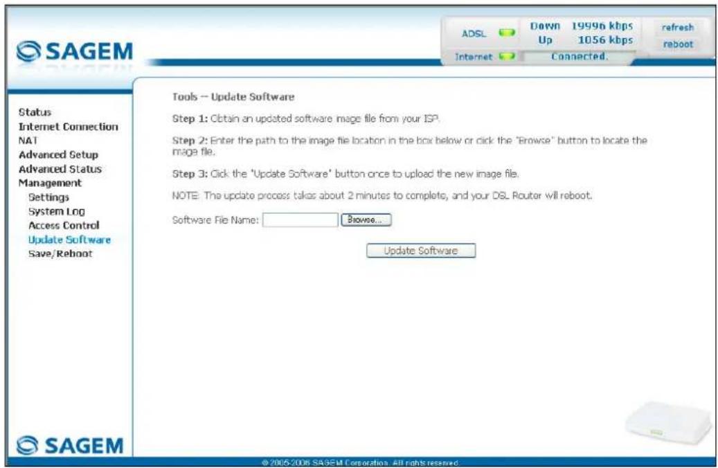
text_image
SAGEM Status Internet Connection NA1 Advanced Setup Advanced Status Management Settings System Log Access Control Update Software Save/Reboot Tools -- Update Software Step 1: Obtain an updated software image file from your ISP. Step 2: Enter the path to the image file location in the box below or click the "Browse" button to locate the image file. Step 3: Click the 'Update Software' button once to upload the new image file. NOTE: The update process takes about 2 minutes to complete, and your DSL Router will reboot. Software File Name: Browse... Update Software © 2005-2006 SAGEM Corporation. All rights reserved.Proceed as follows to update your router's software version:
- Enter the path then the name of the software version file, or
- Click on the Browse button and select the path then the software version file,
- Click on the Update Software button to update the software version.

The process takes around 2 minutes.
The application of a new software version for the router does not modify the current configuration at all.
5.10.5 Save/Reboot
Object: This menu lets you save all the modifications made to the current configuration and restart the router with its new parameters.
- Select the Save/Reboot menu in the Management section to display the following screen:

text_image
SAGEM ADSL Down 19996 kbps Up 1056 kbps refresh reboot Internet Connected. Status Internet Connection NAT Advanced Setup Advanced Status Management Settings System Log Access Control Update Software Save/Reboot Click the button below to save and reboot the router. Save/Reboot © 2005-2006 SAGEM Corporation. All rights reserved.Click on the Save/Reboot button to restart the router.

The process takes around 1 minute.
A countdown is displayed to tell the user how long is left to wait.
6. Internet access service
| This section covers ➤ the introduction § 6.1 | ||
| ➢ connecting to Internet access § 6.2 |
6.1 Introduction
The router has been designed to enable you to access the Internet as simply as possible. Most of the router's parameters are already set:
It is configured by default as a DHCP server.
It relays to the Internet DNS queries from the local network.
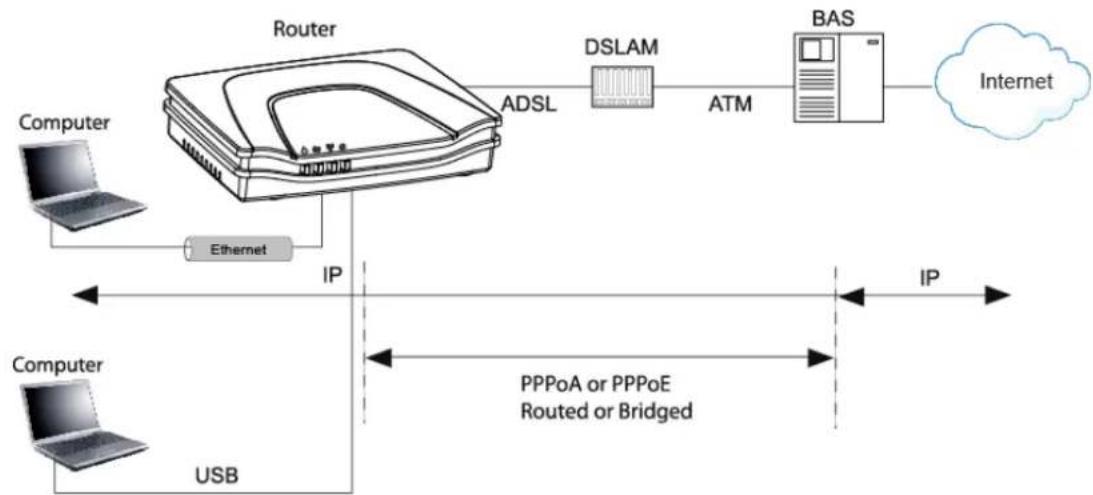
flowchart
graph LR
    A["Computer"] -->|Ethernet| B["Router"]
    B -->|ADSL| C["DSLAM"]
    C -->|ATM| D["BAS"]
    D --> E["Internet"]
    F["Computer"] -->|USB| B
    B -->|IP| G["PPPoA or PPPoE<br>Routed or Bridged"]
    G --> H["IP"]
Using your installation CD-ROM you can quickly obtain Internet access.
The configuration parameters of your router are entered during installation (connection identifier, connection password). These parameters can also be entered or modified in the menu Internet connection of the HTTP configurator (PPP Username, PPP Password).
However, your computers (PC, Mac) must still be configured. To surf the Internet, your PC (or any other type of terminal) must also belong to the network. To do so it requires an address by which it can be identified. All these necessary parameters can be supplied automatically by the router if your computers are in DHCP client mode (default mode for PCs running Windows). Depending on the OS installed on your PC, it may be necessary to restart your PC (or other terminal) after configuring and restarting the router.
Observation: If the terminals are not DHCP clients, your local network then uses a static addressing plan. Check that:
• the router belongs to this addressing plan,
- the default gateway of the equipment in the local network matches the address of your router,
- the DNS addresses are correctly configured in each terminal. The router enables DNS queries to be relayed.
6.2 Connection for Internet access
When installation is complete the "SAGEM" welcome page appears.
You can now surf the Internet.
7. Updating the application
| This section covers | ➢ updating the application version. | P 7-2 |
7 - Updating the application
The router's application version is updated manually by the HTTP configurator (download of a file without extension). Refer to § 5.10.4 of section 5 (Management/Update Software).

To check that the new version has been correctly downloaded, click the command Status/Summary at the top left of the welcome screen of the HTTP configurator.
A. Annex A - Troubleshooting
| This section covers | checking the attribution of an IP address | § A.1 |
| Front Face LEDs § A.2 | ||
| Supervision of your router § A.3 | ||
| the "Diagnostics" tool § A.4 | ||
| interpreting the lights. § A.5 | ||
| reinitialising your router § A.6 | ||
| resetting with the factory configuration. § A.7 | ||
| no-connection mode. § A.8 |
A.1 Checking the attribution of an IP address
A.1.1 In Windows
In Windows 98 and Me
➢ Click button Start, select Execute, enter winipcfg and then click OK; the dedicated application appears.
➢ Check that the entry IP Address contains a value other than 0.0.0.0 (192.168.1.10 for example, for interface ETH).
In Windows XP, 2000
Click button Start, select Execute, enter cmd and then click OK; the command prompt screen appears. Enter ipconfig and then confirm by pressing Enter.
➢ Check that the entry IP Address contains a value other than 0.0.0.0 (192.168.1.10 for example, for interface ETH).

If no address is displayed on the screen, enter ipconfig /release followed by ipconfig /renew.
A.1.2 On a Mac (for example MacOS X)
➢ Click Apple, in the menu bar.
Select System Preferences, and then click the Network icon.
➢ Check that the entry IP Address contains a value other than 0.0.0.0 (192.168.1.10 for example, for interface ETH).
➢ Check that the entry IP Address contains a value other than 0.0.0.0 (192.168.1.10 for example, for interface ETH).

If no address is displayed on screen, click button Apply for the computer to send a DHCP query to the router.

All the troubleshooting procedures described below are undertaken in Windows® XP. These procedures in other Windows operating systems® (98, ME and 2000) can be slightly different.
To help locate the fault, the user has the following sources:
States of Front Face LEDs,
Data accessible by the configurator by "DSL Router" onboard HTTP of your router:
• supervision of the router,
• "Diagnostics" tool.
A.2 Front Face LEDs

When the router is switched on, the "@" LED (Internet) lights in green and gets off then the " 🔊" LED (PWR) lights in green.
| Status Colour @ | ∅ | ∅p | ∅∅ | ||
| On steady | Green Power present | Synchronised ADSL line | USB or ETH line active | Public Address available | |
| Red Failure detected at the tim of starting | x | x | Unconnected line or Public Address unavailable | ||
| Blinking Green x x At LAN traffic rate At WAN traffic rate | |||||
| Blinking quickly | Green | X | ADSL synchronisation training | x | x |
| Blinking slowly | Green | x | Line not connected | ||
| Off | - | Power not present | x | USB or ETH line inactive | Power not present or "Bridge" mode |
A.3 Supervising your router
The supervision box is permanently displayed in a frame at the top right of each window of the configurator.
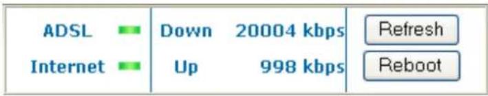
text_image
ADSL Internet Down 20004 kbps Up 998 kbps Refresh RebootLEDs
| ADSL | Green: Synchronised ADSL line.Red: ADSL line not connected. |
| Internet | Green: Public IP address (WAN) distributed to the router.Yellow: Synchronised ADSL line.Red: Public IP address (WAN) not distributed to the router, or ADSL line not connected. |
Transmission rate
| Down | Displays the nominal down line transmission rate |
| Up | Displays the nominal up line transmission rate |
Buttons
| Refresh | Allows data displayed on the screen to be refreshed. |
| Reboot | Allows your router to be started. |
A.4 "Diagnostics" tool
To access this tool:
➢ open your browser and then, in the address bar, enter:
• the following URL : http://myrouter,
• or the following address : http://192.168.1.1.
a "Login" window appears; enter the login and password. Default:
admin in the "User name" field,
admin in the "Password" field.
You have access to the HTTP configurator of your router.
select the heading "Diagnostics" in the suitable list to the left of each window; the following screen appears:
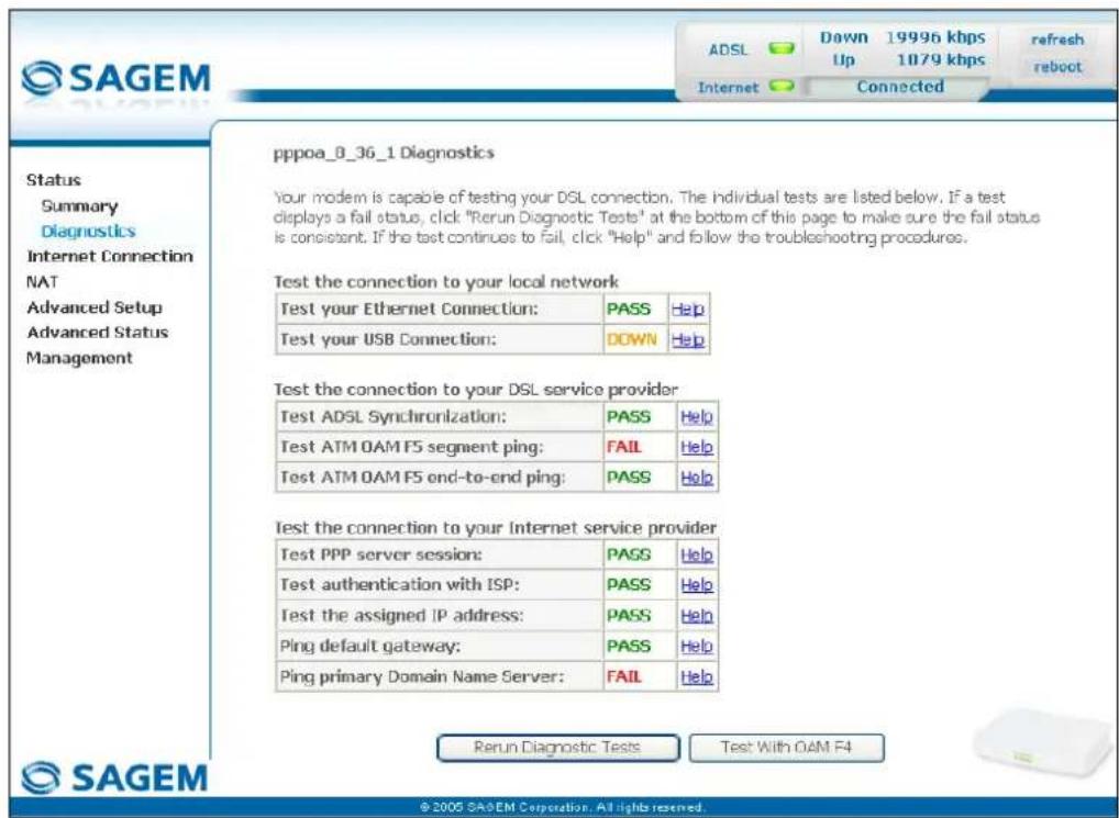
text_image
pppoa_8_36_1 Diagnostics Your modem is capable of testing your DSL connection. The individual tests are listed below. If a test displays a fail status, click "Rerun Diagnostic Tests" at the bottom of this page to make sure the fail status is consistent. If the test continues to fail, click "Help" and follow the troubleshooting procedures. Test the connection to your local network Test your Ethernet Connection: PASS Help Test your USB Connection: DOWN Help Test the connection to your DSL service provider Test ADSL Synchronization: PASS Help Test ATM OAM F5 segment ping: FAIL Help Test ATM OAM F5 end-to-end ping: PASS Help Test the connection to your Internet service provider Test PPP server session: PASS Help Test authentication with ISP: PASS Help Test the assigned IP address: PASS Help Ping default gateway: PASS Help Ping primary Domain Name Server: FAIL Help SAGEM © 2005 SASEM Corporation. All rights reserved.The results of the tests made by the "DSL router" configurator on your modem/router are displayed in the "Diagnostics" window. These tests concern the connections to the LAN, to your DSL Service Provider and to your Internet Service Provider (ISP).

A hypertext link (help) enables the user to access context-related help. This help gives an explanation concerning the state of the connection (PASS in green, DOWN in orange and FAIL in red) and supplies the appropriate troubleshooting procedures.
State of connection
| State Colour Meaning | ||
| PASS | Green Indicates that the test has completed successfully. | |
| DOWN | Orange Indicates that an interface (ETH, USB or Wi-Fi) has not been detected. | |
| FAIL | Red Indicates that the test has failed, or that it is impossible to start a command.Note: Depending on the nature of the test, it is possible that operation of the router or access to the Internet may not be prejudiced. For example if you do a "Ping" either to an ATM OAM F5 segment or to a DNS primary address. | |

If a test displays a "FAIL" state, click on "Help" and then the button "Rerun Diagnostic Tests" at the bottom of the "Help" page, to check that the test has been conclusive. If the test still displays "FAIL", you must follow the troubleshooting procedure displayed on this page.
IMPORTANT
If you experience difficulties connecting to the Internet, we recommend that you restart your router (cf.A.6) or possibly re-establish the factory configuration (cf. § A.7).
A.5 Interpreting the LEDs
A.5.1 The "ADSL" LED blinks slowly
➢ Check the connection of your ADSL filters. Each telephone socket of your installation which is used must be equipped with an ADSL filter.
➢ Check that the RJ11 type line cord delivered with your router is connected to one of your sockets. It is recommended that no telephone extension is used.
Finally, check with your ISP on the availability of the ADSL service on your telephone line.
A.5.2 All LEDs are off
➢ Check that the type of power available in your premises is compatible with the mains voltage required for powering your router.
➢ Check that the delivered power cord is properly connected at one end to the mains power network.
Check that the power connector is inserted correctly in the corresponding connector (power) of the router.
A.6 Reinitialising your router
To Reinitialise your router, click button "Reboot" at the top right of the welcome page of your HTTP configurator. When you click this button all the LEDs get off; the "@" LED (Internet) lights in green and gets off then the "*" LED (PWR) lights in green and the initialisation process starts. It lasts for around a minute.
Note : The green " ☐" (LINE) and ☐(LAN) LEDs light if they are connected.
The "@" LED (Internet) lights in green if "PPP" link is established.
A.7 Re-establishing the factory configuration
To undertake the procedure, there are two possibilities:
1) Using the HTTP configurator
- In the welcome screen of your HTTP configurator, select the heading Management followed by the sub-menu Restore Default in the Settings menu (cf. 5.10.1.3).
2) Using the "REG" button - press the REG pushbutton for at least 15 seconds; all the LEDs get off; the "@" LED (Internet) lights in green and gets off then the "◀" LED (PWR) lights in green and the process for returning to the factory configuration starts.

This operation deletes the entire personalised configuration of your router: Password, Configuration, etc. It lasts for around 2 minutes.

After a return to factory configuration, it is necessary to install your router again using the installation CD-ROM, or to enter again the ADSL connection data supplied by your Internet Service Provider (ISP) (cf. Internet Connection section - § 5.6).
A.8 Offline mode
To start configuring the router in HTTP mode, the browser opens, the default IP address of the router's LAN interface appears in the browser's Address field but the home screen does not appear.
The screen opposite appears.
Click
Connect
The screen opposite appears.
Click
Settings...

text_image
Web page unavailable while offline The Web page you requested is not available offline. To view this page, click Connect. Connect Stay Offline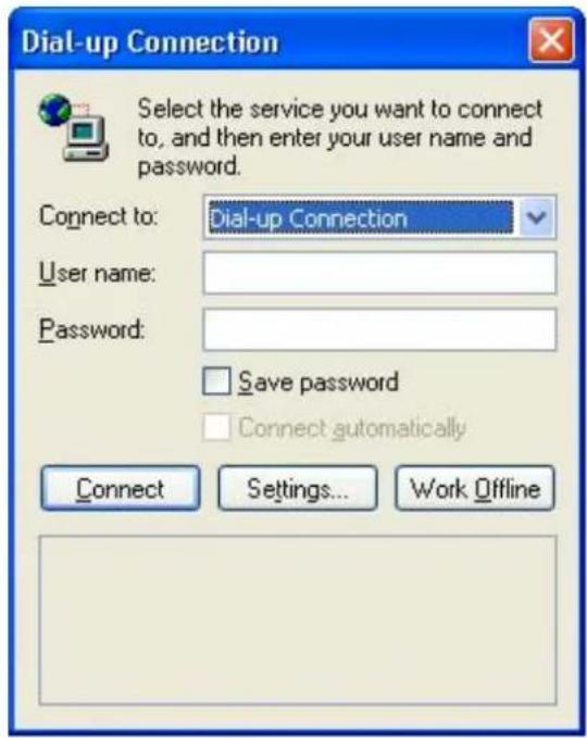
text_image
Dial-up Connection Select the service you want to connect to, and then enter your user name and password. Connect to: Dial-up Connection User name: Password: Save password Connect automatically Connect Settings... Work OfflineThe screen opposite appears.
Select the Connections tabs and then the "Never dial a connection" ^1 .
Click OK to confirm your choice.
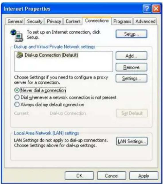
text_image
Internet Properties General Security Privacy Content Connections Programs Advanced To set up an Internet connection, click Setup. Setup... Dial-up and Virtual Private Network settings Dial-up Connection [Default] Add... Remove Choose Settings if you need to configure a proxy server for a connection. Settings... Never dial a connection Dial whenever a network connection is not present Always dial my default connection Current Dial-up Connection Set Default Local Area Network (LAN) settings LAN Settings do not apply to dial-up connections. LAN Settings... Choose Settings above for dial-up settings. OK Cancel ApplyIn the menu bar, select the "File" menu then deselect the "Work Offline" command.
Click OK in the browser's "Address" field to display the home screen.
B. Annex B - Warnings for safety
| This section covers ➢ | Warnings for safety § B.1 | |
| ➢ the CE conformity declaration § B.2 |
B.1 Warnings for safety
The router is in compliance with standard EN 60950 Ed December 2001.
The safety levels in the sense of this standard are as follows:
B.1.1 Safety levels in relation to the case
| Connectors Position Safety level | ||
| LINE | ADSL port TNV3 | 1 |
| USB | USB interface port SELV | 2 |
| ETH | Ethernet port SELV | 2 |
| PWR | Primary power port HPV | 3 |
B.2 CE compliance declaration
CE
Products bearing this symbol are in compliance with EMC regulations and the Low Voltage Directive published by the European Community Commission (CCE)
Sagem communication declares that the SAGEM F@st™ 1201 and SAGEM F@st™ 1241 products are in compliance with the requirements of European directives 1995/5/CE and with the essential requirements of directives 89/336/CEE of 03/05/1989 and 73/23/CEE of 19/02/1973, and that they efficiently use the spectrum attributed to terrestrial or space radio communications.
The CE conformity declaration of each product (SAGEM F@st ^TM 1201 or SAGEM F@st ^TM 1241) is made in the context of the R&TTE directive.
This conformity is presumed through the complete compliance with European harmonised standards.
Sagem communication declines all liability if the regulations in force in the place of installation are not followed.
The CE conformity declaration of each product (SAGEM F@st ^TM 1201 or SAGEM F@st ^TM 1241) is present in the form of a file with pdf extension in the CD-ROM delivered with the product.
C. Annex C - Environment
| This section covers ➤ directive E 2002/96/CE § C.1 |
C.1 Directive E 2002/96/CE
ENVIRONMENT
Preservation of the environment as part of a sustainable development logic is an essential concern of Sagem Communication.
Sagem Communication's aim is to operate systems safeguarding the environment and consequently it has decided to integrate environmental performance considerations in the life cycle of its products, from manufacturing to commissioning, use and disposal.

THE PRODUCT
The crossed-out waste bin marked on the product or its accessories means that the product belongs to the family of electrical and electronic equipment.
In this respect, the European regulations require you to dispose of it selectively:
- At sales points on purchasing similar equipment,
- At the collection points made available to you locally (drop-off center, selective collection, etc.).
In this way, you can participate in the re-use and upgrading of Electrical Electronic Equipment Waste, which can have an effect on the environment and health.
D. Annex D - Technical Characteristics
| This section covers ➢ | mechanics and displays § D.1 | |
| ➤ the characteristics of the different interfaces § D.2 | ||
| ➤ environmental characteristics § D.3 | ||
| ➤ the application and the protocols § D.4 |
D.1 Mechanics; Display
| Mechanical characteristics | |
| Dimensions (mm) | Width : 140 mm |
| Depth : 95 mm | |
| Thickness : 32 mm | |
| Weight of router : 200 gr | |
| Display | ||
| Marking | Abbreviation | Meaning |
 | PWR | • Green/Red Power LED |
| [1322D] | ADSL | • Green ADSL LED |
 | LAN | • Green local network (LAN) LED |
| [WXXT] | Internet | • Green/Red Internet LED |
D.2 Characteristics of the different interfaces
| Ethernet LAN interface | |
| Transmission rate | 10 Mbit/s or 100 Mbit/s, self-configurable |
| Half/Full Duplex | |
| Standard | 802.3 mm |
| Connection technology | RJ45Type MDI or MDI-x self-detecting portCrossed or straight cord |
| ADSL/ADSL2/ADSL2+ interface | |
| Transmission code | DMT |
| Standards supported | High-performance secure Bridge/Router with ADSL/ADSL2/ADSL2+ interface, |
| G.994.1 (G.Handshake) | |
| Maximum upward transmission rate | 1.3 Mbit/s |
| Maximum downward transmission rate | 24.5 Mbit/s |
| Latency | Simple (Fast or Interlaced) |
| USB Interface | |
| Transmission rate | • 1.5 Mbit/s to 12 Mbit/s |
| Standard | • USB 1.1 |
| Data | • Asynchronous |
| Transmission mode | • bidirectional |
| Consumption | • none (only a voltage detection for the high-impedance port of a computer) |
| Connection technology | • USB - Type B |
| Input/Output supply | |
| Type | Plug-in external adapter unit |
| Class | II |
| Input | 198 to 253 VAC, 50/60 Hz, 0.4 A |
| Output | +7.5 VDC/700 mA |
| Mains connection technology | Europlug type C socket |
D.3 Environmental characteristics
| Climatic and mechanical environment | |
| Storage | • ETS 300 019-1-1 Category T1.2 |
| Transport | • ETS 300 019-1-2 Category T2.3 |
| Operation | • ETS 300 019-1-3 Category T3.2Temperature: +5°C/+45°C |
| Electrical robustness | |
| Standard | • UIT-T K21 Ed 2000 : basic level |
| Electromagnetic compatibility | |
| Susceptibility/Emission | EN 301 489-1 Ed. 2002 |
| EN 301 489-17 Ed. 2002 | |
| Radio part for ISM band at 2.4 GHz | |
| Emission 802.11g/b | • ETR 300 328-2 Ed . July 2000 |
D.4 Application and protocols
| IP characteristics | |
| TCP-IP, UDP, ICMP, ARP | |
| DHCP Client/Server/Relay | |
| DNS Server/Relay | |
| FTP Client/Server | |
| TFTP Client/Server | |
| HTTP Client/Server | |
| Routing (LAN and WAN) | Static |
| NAT/PAT | 8 maps maximum |
| Encapsulation protocols | |
| PPP over ATM (PPPoA) | RFC 2384 |
| PPP over Ethernet (PPPoE) | RFC 2516 |
| Routed or Bridged | RFC 2684 |
| Configuration | |
| HTTP | • LAN or WAN port (with specific option) |
| Management | • From ETH, USB and WAN (with specific option) |
| Downloading of version | • Client by http mode |
E. Annex E - Default configuration
| This section covers | ➢ the default username and password | § E.1 |
| ➢ the default configuration for the local network (LAN) | § E.2 | |
| ➢ the default configuration for the remote network (WAN) | § E.3 |

This section indicates the values of the default parameters of your router when it leaves the factory.
These default parameters can be modified by a particular preconfiguration of your router.
E.1 Default username and password
The default access level is Administrator. Its associated "username" and "password" are:
| Username | admin |
| Password | admin |
E.2 Default configuration for the local network(LAN)
The following table gives the values of the principal LAN parameters of your router (ETH, USB):
| LAN characteristics Value State | ||
| ETH IP address | 192.168.1.1 Internet and | HTTP configurator access or to a TV decoder |
| USB IP address | Internet and HTTP configurator access | |
| BROADCAST, ARP, MULTICAST Activated | ||
| Router The LAN traffic is routed to your ISP | ||
| NAT/PAT Activated | ||
E.3 Default configuration for the remote network (WAN)
| Designation Value | |
| VPI 8 | |
| VCI 35 | |
| Linking protocol PPPoA | |
| DNS relay | |
| DHCP server | |
| ADSL/ADSL2/ADSL2+ Multimode |
F. Annex F - Glossary
Glossary
| ACL | Access Configuration List |
| ADSL | Asynchronous Digital Subscriber Line |
| ARP | Address Resolution Protocol |
| CC | Continuity Check |
| CCK | Complimentary Code Keying |
| CHAP | Challenge Handshake Authentication Protocol |
| CLI | Command Line Interface |
| CTS | Clear To Send |
| DBPSK | Demodulator Baseband Phase Shift Keying |
| DECT | Digital Enhanced Cordless Telephone |
| DHCP | Dynamic Host Configuration Protocol |
| DMT | Discrete MultiTone |
| DNS | Domain Name Server |
| DQPSK | Differential Quadrature Phase Shift Keying |
| DSSS | Direct Sequence Spread Spectrum |
| DTIM | Delivery Traffic Indication Message |
| DTMF | Dual Tone Multi-Frequency |
| ESSID | Extended Service Set IDentifier |
| FAI | Fournisseur d'Accès à Internet |
| FHSS | Frequency Hopping Spread Spectrum |
| FTP | File Transfert Protocol |
| HTML | Hyper Text Markup Language |
| HTTP | Hyper Text Transfer Protocol |
| ICMP | Internet Control Message Protocol |
| IEEE | Institute of Electrical and Electronics Engineers |
| IEEE 802.11b/g | Specifications which use the MAC protocol suitable for the wireless local network (WLAN) in the 2.4 GHz band |
| IGMP | Internet Group Membership Protocol |
| IP | Internet Protocol |
| IPQoS | Qualité IP |
| ISP | Internet Service Provider |
| LAN | Local Area Network |
| LCP | Link Control Protocol |
| LLC | Logical Link Control (encapsulation avec en-tête) |
| MAC | Medium Access Control |
| MDI | Media Dependent Interface |
| MER | MAC Encapsulation Routing |
| MTU | Maximum Transfer Unit |
| NAPT | Network Address Port Translation |
| NAT | Network Address Translation |
| OAM | Operation, Administration and Maintenance |
| PA | Point d'Accès |
| PAP | Password Authentication Protocol |
| PCI | Peripheral Component Interconnect |
| PCM | Pulse Code Modulation |
| PCMA | Pulse Code Modulation Loi A |
| PCMCIA | Personal Computer Memory Card International Association |
| PCMU | Pulse Code Modulation Loi mu |
| PID Protocol Identifier | |
| PING | Packet InterNet Groper |
| PLC | Paquet Loss Concealment |
| POP P | oint de Présence |
| POTS | Plain Old Telephone Service |
| PSTN | Public Switching Telephonic Network |
| PPP | Point to Point Protocol |
| PPPoA | PPP over ATM |
| PPPoE | PPP over Ethernet |
| PVC | Permanent Virtual Circuit |
| QoS | Quality of Service |
| RADIUS | Remote Authentication Dial-In User Service |
| RFC | Request For Comments |
| RGW | Residential GateWay (Passerelle Résidentielle) |
| RNIS | Réseau Numérique Intégration de Services |
| RIP | Routing Information Protocol |
| RTCP Real | Time Control Protocol |
| RTP | Real-time Transport Protocol |
| SCR | Sustained Cell Rate |
| SMTP | Simple Mail Transfer Protocol |
| SNDCP | Sub Network Dependent Convergence Protocol |
| SNAP | SubNetwork Attachment Point |
| SNMP | Simple Network Management Protocol |
| SSID | Service Set IDentifier |
| STB | Set Top Box |
| TCP | Transmission Control Protocol |
| TELNET | TELecommunication NETwork |
| TFTP | Trivial File Transfer Protocol |
| UBR | Unspecified Bit Rate |
| UDP User | Datagram Protocol |
| URL | Uniformed Resource Locator |
| USB | Universal Serial Bus |
| UTP | Unshielded Twisted Pair |
| VAD | Voice Activity Detection |
| VBR-nrt | Variable Bit Rate - non real time |
| VBR-rt | Variable Bit Rate - real time |
| VC Virtual Channel | |
| VCC | Virtual Channel Connection |
| VCI | Virtual Channel Identifier |
| VC MUX | VC MultipleXing (encapsulation sans en-tête) |
| VP Virtual Path | |
| VPI | Virtual Path Identifier |
| VPN | Virtual Private Network |
| WAN | Wide Area Network |
| WEB Meshed network of information servers | |
| WFQ | Weighted Fair Queuing |
| WLAN | Wireless Local Area Network |
G. Annex G - Connector Technology
| This section covers | ➢ pinouts of the "LINE" connector | § G.1 |
| ➢ pinouts of the "PWR" connector | § G.2 | |
| ➢ pinouts of the "ETH" connector | § G.3 | |
| ➢ pinouts of the "USB" Connector | § G.4 |
G.1 Pinouts of the "LINE" connector
The equipment is connected to ADSL using a RJ11 fixed connector (6 contacts).
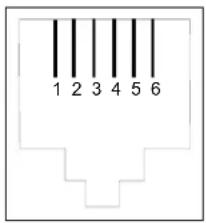
text_image
1 2 3 4 5 6| Contact N° Signal Meaning | |
| 3 LINE-A Line A signal | |
| 4 LINE-B Line B signal | |
| 1 NC Not connected | |
| 2 NC Not connected | |
| 5 NC Not connected | |
| 6 NC Not connected |
G.2 Pinouts of the "PWR" connector
The mains unit is connected to the equipment using the miniature fixed connector of the case.

| Pin Signal Meaning | ||
| Internal +7.5 V DC "+" connection | ||
| External Earth DC "-" connection | ||
G.3 Pinouts of the "ETH" connector
The Ethernet interface is connected to the equipment using a RJ45 fixed connector (8 contacts).
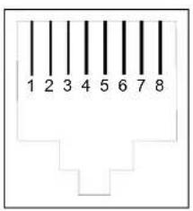
text_image
1 2 3 4 5 6 7 8| Contact N° Signal Meaning | ||
| 1 TXD+ (+) Emission to terminal | ||
| 2 TXD- (-) Emission to terminal | ||
| 3 RXD+ (+) Reception of terminal | ||
| 4 NC Not connected | ||
| 5 NC Not connected | ||
| 6 RXD- | (-) Reception of terminal | |
| 7 NC Not connected | ||
| 8 NC Not connected | ||

The Ethernet port is self-detecting. You can use either straight or crossed cables. An emission or reception signal is detected automatically.
G.4 Pinouts of the "USB" connector
The "USB" interface is connected to the equipment using a type B female USB fixed connector.
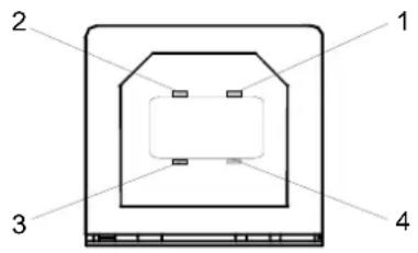
text_image
1 2 3 4| Contact N° Signal Meaning | ||
| 1 Vcc PC power (+) | ||
| 2 - Data Subscriber line signal | ||
| 3 + Data Subscriber line signal | ||
| 4 | G | r o |
u
n