Smart-UPS SRT004 - UPS APC - Free user manual and instructions
Find the device manual for free Smart-UPS SRT004 APC in PDF.

| Product Type | UPS (Uninterruptible Power Supply) |
| Model | Smart-UPS SRT004 |
| Brand | APC by Schneider Electric |
| Topology | Line-Interactive with pure sine wave output |
| Power Capacity | 1000 VA / 800 W |
| Input Voltage | 230 V nominal |
| Output Voltage | 230 V ± 5% |
| Frequency | 50/60 Hz auto-sensing |
| Battery Type | Lead-acid, maintenance-free, user-replaceable |
| Typical Backup Time (half load) | Approximately 15 minutes |
| Outlets | 8 x IEC 320 C13 (battery-backed) |
| Dimensions (H x W x D) | 432 x 85 x 495 mm (2U rack format) |
| Weight | 18.5 kg |
| Operating Temperature | 0 to 40 °C |
| Management | USB, RS-232, and SmartSlot for optional network management card |
| Software | PowerChute Business Edition or Personal Edition |
| Safety Certifications | CE, CB report |
| Warranty | 2 years (extendable) |
| Surge Protection | Yes |
| Noise Level | 45 dBA |
| Battery Replacement | Hot-swappable (no downtime) |
| Mounting | 2U rackmount |
| Color | Black |
Frequently Asked Questions - Smart-UPS SRT004 APC
User questions about Smart-UPS SRT004 APC
0 question about this device. Answer the ones you know or ask your own.
Ask a new question about this device
Download the instructions for your UPS in PDF format for free! Find your manual Smart-UPS SRT004 - APC and take your electronic device back in hand. On this page are published all the documents necessary for the use of your device. Smart-UPS SRT004 by APC.
USER MANUAL Smart-UPS SRT004 APC
Installation Guide Smart-UPS™ On-Line SRT001/SRT004/SRT005/SRT008
Important Safety Information
Read the instructions carefully to become familiar with the equipment before trying to install, operate, service or maintain it. The following special messages may appear throughout this manual or on the equipment to warn of potential hazards or to call attention to information that clarifies or simplifies a procedure.

The addition of this symbol to a Danger or Warning safety label indicates that an electrical hazard exists which will result in personal injury if the instructions are not followed.

This is the safety alert symbol. It is used to alert you to potential personal injury hazards. Obey all safety messages that follow this symbol to avoid possible injury or death.

CAUTION
CAUTION indicates a potentially hazardous situation which, if not avoided, can result in minor or moderate injury.
CAUTION
CAUTION addresses practices not related to physical injury including certain environmental hazards, potential damage or loss of data.

Safety and General Information
Inspect the package contents upon receipt. Notify the carrier and dealer if there is any damage.
Adhere to all local and national electrical codes.

Recycle the packaging.
Deenergizing safety
The UPS contains internal batteries and may present a shock hazard even when disconnected from the branch circuit (mains). Before installing or servicing the equipment, check that the internal batteries are removed, that external extended run batteries are disconnected and the branch circuit (mains) is disconnected.
Hardwire safety
- Verify that all branch circuit (mains) and low voltage (control) circuits are deenergized, and locked out before installing cables or making connections, whether in the junction box or to the UPS.
- Wiring by a qualified electrician is required.
- Adhere to all national and local codes.
- Select wire size and connectors according to national and local codes.
- Strain relief is required for all hardwiring.
- All openings allowing access to UPS hardwiring terminals must be covered. Failure to do so may result in personal injury or equipment damage.
Package Contents
The UPS and PDU models may vary in appearance from those depicted in the diagrams. The PDU installation procedure is similar for SRT001/SRT004/SRT005 models.
| SRT001 SRT004 SRT005 | ||
1 Output Hardwire Kit• 4 screws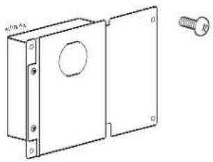 | • 1 PDU• 4 screws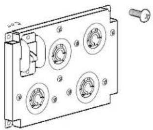 | • 1 PDU• 4 screws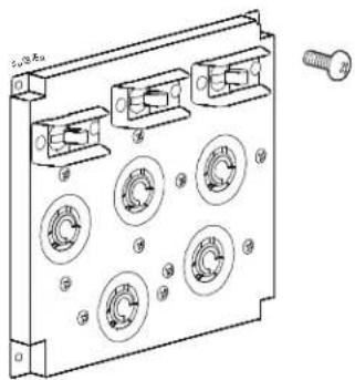 |
| SRT008 | ||
• 1 PDU• 2 screws | ||
Remove Standard PDU
UPS models SRT5K/SRT6K

CAUTION
DAMAGE TO EQUIPMENT OR PERSONNEL
- Adhere to all local and national electrical codes.
- Wiring must be performed by a qualified electrician.
Failure to follow these instructions can result in equipment damage and minor or moderate injury.
Disconnect equipment connected to the UPS.
- Press the POWER ON/OFF button located on the front of the UPS. Select Turn Off Immediately to turn the UPS output off.
- Disconnect all the battery modules.
- Disconnect all the external battery packs (XLBPs), if installed.
- Disconnect the UPS from the utility power. Disconnect methods will vary depending on the model.
- Unplug the UPS from the wall receptacle.
- Switch the utility circuit breaker off.
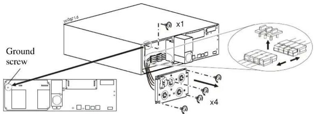
PDU with 4 pin connector in SRT5K/SRT6K models
Remove the ground screw and the standard PDU. Remove the connector clip and disconnect the 4 pin connector.
text_image
Ground screw x1 x4PDU with 2 pin connector in SRT5KRMXLW-HW model
Remove the ground screw and the standard PDU. Remove the connector clip and disconnect the 2 pin connector.

text_image
Ground screw x1 x4Install PDU
PDU models SRT004/SRT005
SRT004
| PDU UPS Models | |
| SRT004 SRT5KXLT | SRT5KRMXLT |
| SRT5KXLT-IEC | |
| SRT5KRMXLT-IEC | |
| SRT5KRMXLW-HW | |
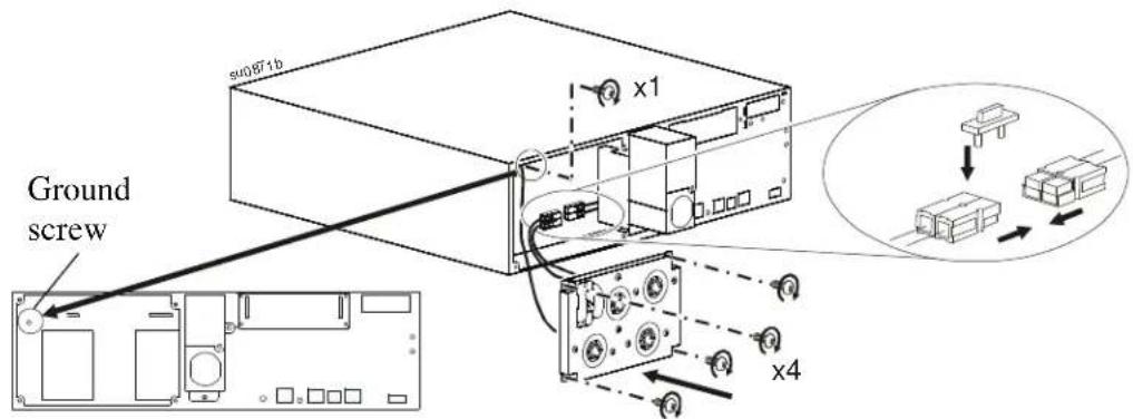
Note: Secure the 2 pin connector from the PDU to the appropriate connector on the UPS. Ignore any additional connectors on the UPS. Connect the ground cable to the ground screw.
Connect the 2 pin connector and install the connector clip. Install the SRT004 PDU and secure the ground screw.
text_image
Ground s#0971b x1 x4SRT005
| PDU UPS | Models |
| SRT005 SRT6KXLT | SRT6KRMXLT |
| SRT6KXLT-IEC | |
| SRT6KRMXLT-IEC |
Note: Secure the 4 pin connector on the PDU to the appropriate connector on the UPS. Ignore any additional connectors on the UPS. Connect the ground cable to the ground screw.
Connect the 4 pin connector and install the connector clip. Install the SRT005 PDU and secure the ground screw.

text_image
su0871c Ground screw x1 x4Install Output Hardwire Kit
Model SRT001
| PDU UPS Models | |
| SRT001 SRT5KXLI | SRT5KRMXLI |
| SRT5KXLT | |
| SRT5KRMXLT | |
| SRT5KXLT-IEC | |
| SRT5KRMXLT-IEC | |
Note: Secure the 2 pin connector on the PDU to the appropriate connector on the UPS. Ignore any additional connectors on the UPS. Connect the ground cable to the ground screw.

CAUTION
DAMAGE TO EQUIPMENT OR PERSONNEL
- Verify that all branch circuit (mains) and low voltage (control) circuits are deenergized, and locked out before installing cables or making connections, whether in the junction box or to the UPS.
- Wiring by a qualified electrician is required.
- Check national and local codes before wiring.
- Strain reliefs are not supplied with the unit. Snap-In type strain reliefs are recommended.
- All openings that allow access to UPS hardwire terminals must be covered.
- Select wire size and connectors according to national and local codes.
- Recommended output terminal screw torque: 1.58 - 1.81 Nm (14-16 lbf-in).
Failure to follow these instructions can result in equipment damage and minor or moderate injury.
1
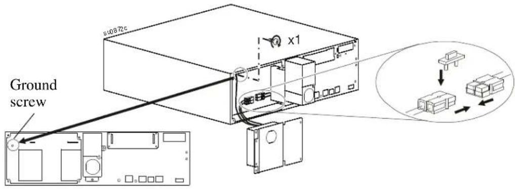
Connect the 2 pin connector and install the connector clip. Secure the ground screw.
text_image
Ground s10872c x1| 2 | Secure the output hardwire kit to the UPS.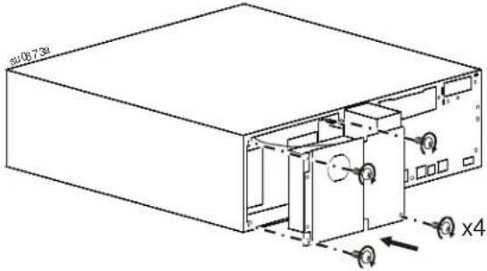 | 3 | Remove the output hardwire box.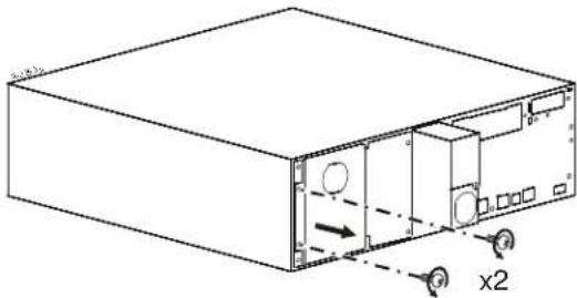 |
| 4 | Connect the output wires.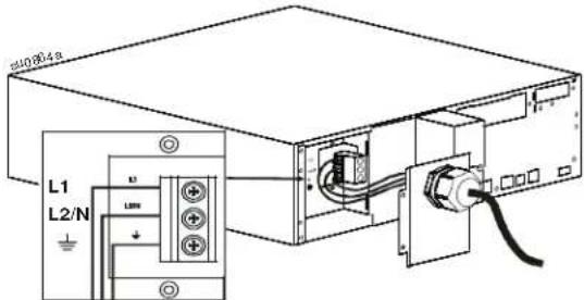 | 5 | Secure the output panel to the UPS.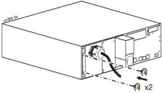 |
Replace Standard PDU
UPS models SRT8K/SRT10K
| PDU UPS Models | |
| SRT008 SRT8KXLT | SRT8KRMXLT |
| SRT8KXLT-IEC | |
| SRT8KRMXLT-IEC | |
| SRT10KXLT | |
| SRT10KRMXLT | |
| SRT10KXLT-IEC | |
| SRT10KRMXLT-IEC | |
1 Remove the rear access cover. Remove AC wiring box.
text_image
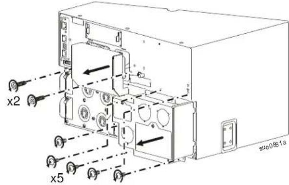
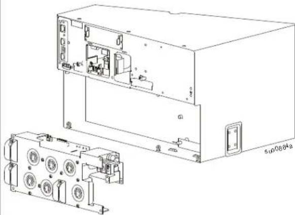
x2 x5 s400861a2 Disconnect the ribbon cable. Disconnect the output power cable.
natural_image
Technical line drawing of an electronic device casing with ports and components (no text or symbols)③ Remove the screws that secure the PDU to the UPS.

text_image
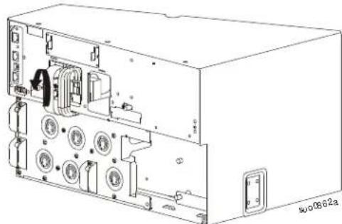
x2 s40063a4 Remove the PDU from the UPS.
natural_image
Technical line drawing of an electronic device showing internal components and wiring (no text or symbols)
text_image
5 Install SRT008 PDU. x2 suo0863b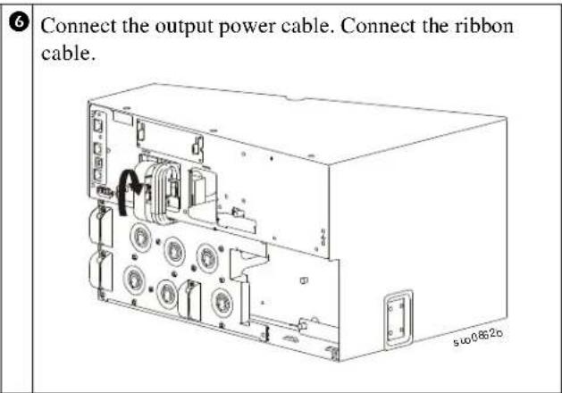
text_image
6 Connect the output power cable. Connect the ribbon cable.
text_image
Install the rear access cover. Install the AC wiring box. x2 x5Configure UPS for PDU Panel
Reconfigure the UPS, using the display interface, to work with the new PDU.
- Reconnect internal RBC.
- Reconnect the XLBP if installed.
- Reconnect the UPS to utility power. Do not turn on the UPS output.
- Configure the PDU once the display interface message is visible.
- Navigate to the User Mode. Change the UPS User Mode to Advance User Mode. Main Menu > Configuration > Display > User Mode
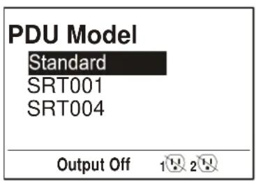
- Navigate to the PDU Model to configure the PDU. Main Menu > Configuration > UPS > PDU Model
- Select the appropriate PDU from the given options and press OK button. Note: The Standard PDU option is the factory default.
PDU options in SRT5K UPS PDU option in SRT6K UPS PDU option in SRT8K/SRT10K UPS
text_image
PDU Model Standard SRT001 SRT004 Output Off 1 2
text_image
PDU Model Standard SRT005 Output Off 1 2 3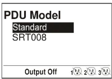
text_image
PDU Model Standard SRT008 Output Off 1 2 3- Wait for 10 seconds for the display interface to reboot.
- Verify that PDU model is updated. Display Navigation: Main Menu > Configuration > UPS > PDU Model
- Turn on the UPS output.