
Smart-UPS Modular Ultra SRYL5K15RMXLT - UPS APC - Free user manual and instructions
Find the device manual for free Smart-UPS Modular Ultra SRYL5K15RMXLT APC in PDF.


| Product Type | Uninterruptible Power Supply (UPS) |
| Model | Smart-UPS Modular Ultra SRYL5K15RMXLT |
| Brand | APC by Schneider Electric |
| Power Rating | 5 kVA / 4.5 kW |
| Input Voltage | 200-240 VAC |
| Output Voltage | 200-240 VAC |
| Input Frequency | 50/60 Hz auto-sensing |
| Output Frequency | 50/60 Hz ± 3% |
| Waveform Type | Sine wave |
| Battery Type | Maintenance-free sealed lead-acid (VRLA) |
| Typical Backup Time (Half Load) | About 20 minutes |
| Typical Backup Time (Full Load) | About 7 minutes |
| Dimensions (H x W x D) | 17.0 x 17.5 x 24.0 inches (432 x 445 x 610 mm) |
| Weight (with batteries) | About 110 lbs (50 kg) |
| Rack Height | 4U |
| Interface Ports | SmartSlot, USB, Serial, EPO |
| Management | Network Management Card (optional), PowerChute software |
| Key Features | Hot-swappable batteries, Modular design, Automatic Voltage Regulation (AVR), Surge protection |
| Maintenance & Cleaning | Keep vents clean, avoid dust, check battery status regularly |
| Safety Certifications | UL, cUL, FCC, CE, VDE |
| Spare Parts & Repairability | Batteries replaceable onsite; modular components allow easy service |
| Operating Temperature | 32°F to 104°F (0°C to 40°C) |
| Warranty | 2 years (extendable) |
Frequently Asked Questions - Smart-UPS Modular Ultra SRYL5K15RMXLT APC
User questions about Smart-UPS Modular Ultra SRYL5K15RMXLT APC
0 question about this device. Answer the ones you know or ask your own.
Ask a new question about this device
Download the instructions for your UPS in PDF format for free! Find your manual Smart-UPS Modular Ultra SRYL5K15RMXLT - APC and take your electronic device back in hand. On this page are published all the documents necessary for the use of your device. Smart-UPS Modular Ultra SRYL5K15RMXLT by APC.
USER MANUAL Smart-UPS Modular Ultra SRYL5K15RMXLT APC
Smart-UPS™ Modular Ultra Uninterruptible Power Supply
User Manual
SRYL5K15RMXLT SRYL5K20RMXLT
SRYL10K15RMXLT SRYL10K20RMXLT
SRYL15K15RMXLT SRYL15K20RMXLT
SRYL20K20RMXLT
EN 990-6492A
06/2023


Legal Information
The Schneider Electric brand and any trademarks of Schneider Electric SE and its subsidiaries referred to in this guide are the property of Schneider Electric SE or its subsidiaries. All other brands may be trademarks of their respective owners.
This guide and its content are protected under applicable copyright laws and furnished for informational use only. No part of this guide may be reproduced or transmitted in any form or by any means (electronic, mechanical, photocopying, recording, or otherwise), for any purpose, without the prior written permission of Schneider Electric.
Schneider Electric does not grant any right or license for commercial use of the guide or its content, except for a non-exclusive and personal license to consult it on an "as is" basis. Schneider Electric products and equipment should be installed, operated, serviced, and maintained only by qualified personnel.
As standards, specifications, and designs change from time to time, information contained in this guide may be subject to change without notice.
To the extent permitted by applicable law, no responsibility or liability is assumed by Schneider Electric and its subsidiaries for any errors or omissions in the informational content of this material or consequences arising out of or resulting from the use of the information contained herein.
Contents
Important Safety Instructions .... 5
Product Handling Guidelines .... 5
FCC Class A Radio Frequency Warning 6
Product Overview 7
System Configuration....7
Replacement Modules 7
Specifications....8
Environmental 8
Physical 8
Battery 8
Electrical 9
Wiring (Hardwire)....10
Package contents 11
UPS 11
XBP 11
Installation.... 12
Unpacking 12
Install Frames in a 4 Post Rack 13
Install Frames in a 2 Post Rack 19
Install Power Module(s) and Battery Module(s) 24
Remove Blanking Panels....25
Remove Power Module and Battery Module 25
Rear Panel Features.... 27
UPS Frame 27
Battery Frame 28
Front Panel Features 28
UPS 28
Hardwiring.... 29
Terminal Configuration....30
Connect Battery Frame.... 31
Connect a single battery frame to UPS 31
Connect multiple battery frames to UPS 32
Battery Cable Extension 34
Operation 35
Modes 35
Set the UPS to Manual Bypass Mode 38
One Line Diagram Status Indicators 39
Status LEDs 40
Start Up 41
Turn on / Turn off the UPS 41
LCD Display 43
UPS Menu Overview 48
Configuration 51
Startup configuration 51
General settings 53
Control 67
UPS 67
Display.... 69
Login to LCD Display 70
Update Firmware 72
Through USB....72
Through NMC web page 73
Download Log Files 74
Through USB....74
Through NMC web page 74
Emergency Power Off.... 75
Network Management Interface.... 77
Smart Battery Management 79
Troubleshooting 81
Transport 84
Service....84
Limited Factory Warranty.... 85
APC Worldwide Customer Support 86
Important Safety Instructions
SAVE THESE INSTRUCTIONS - This manual contains important instructions that should be followed during installation and maintenance of APC TM Smart-UPS TM Modular Ultra series of equipment and batteries.

Read the Safety Guide supplied with the equipment to become familiar with the safety requirements before trying to install or operate the UPS.
Read the user documentation to become familiar with the equipment before trying to install or operate it.
The following special messages may appear throughout this document or on the equipment to warn of potential hazards or to call attention to information that clarifies or simplifies a procedure.

The addition of this symbol either to a “Danger” or “Warning” safety label indicates that an electrical hazard exists that will result in personal injury if the instructions are not followed.

This is the safety alert symbol. It is used to alert you to potential personal injury hazards. Obey all safety messages that follow this symbol to avoid possible injury or death.

DANGER
DANGER indicates a hazardous situation which, if not avoided, will result in death or serious injury.

WARNING
WARNING indicates a hazardous situation which, if not avoided, could result in death or serious injury.

CAUTION
CAUTION indicates a hazardous situation which, if not avoided, could result in minor or moderate injury.
NOTICE
NOTICE is used to address practices not related to physical injury.
Product Handling Guidelines
Inspect the package contents upon receipt. Notify the carrier and dealer if there is any damage.
 |  |  |  |  |  |
| <18 kg | 18-32 kg | 32-55 kg | >55 kg | ||
| <40 lb | 40-70 lb | 70-120 lb | >120 lb |
FCC Class A Radio Frequency Warning
This equipment has been tested and found to comply with the limits for a Class A digital device, pursuant to part 15 of the FCC Rules. These limits are designed to provide reasonable protection against harmful interference when the equipment is operated in a commercial environment. This equipment generates, uses, and can radiate radio frequency energy and, if not installed and used in accordance with the instruction manual, may cause harmful interference to radio communications. Operation of this equipment in a residential area is likely to cause harmful interference in which case the user will be required to correct the interference at their own expense.
Product Overview
APC Smart-UPS Modular Ultra is a high-performance, Uninterruptible Power Supply (UPS) designed to power high availability servers and other sensitive electronic equipment. It helps to provide conditioned, reliable AC power to connected equipment, as well as helps to provide protection from power blackouts, brownouts, swells, sags, and surges.
The UPS is modular in design and can be configured to deliver different output power at different levels of redundancy.
System Configuration
| Model UPS | Frame | N+0 Redundancy N+1 Redundancy | |||||
| Battery Frame | Power Module | Battery Module | Battery Frame | Power Module | Battery Module | ||
| SRYL5K15RMXLT SRYL5K20RMXLT | 1 | - | 1 | 1 | - | 2 | 2 |
| SRYL10K15RMXLT SRYL10K20RMXLT | 1 | - | 2 | 2 | - | 3 | 3 |
| SRYL15K15RMXLT SRYL15K20RMXLT | 1 | - | 3 | 3 | 1 | 4 | 4 |
| SRYL20K20RMXLT 1 | 1 4 4 1 | 5 5 | |||||
NOTE: The numbers in the above table denote the quantity of the particular component.
| Model Input current rating | |
| SRYL5K15RMXLT | 100 ASRYL10K15RMXLT |
| SRYL15K15RMXLT | |
| SRYL5K20RMXLT | 125 A |
| SRYL10K20RMXLT | |
| SRYL15K20RMXLT | |
| SRYL20K20RMXLT | |
Replacement Modules
| Model Description | |
| SRYLBM Replacement Battery Module | |
| SRYLRMXBP External Battery Pack (XBP) - Rack Mount | |
| SRYL5KPMT | 5 kVA / 5 kW Power Module - 208 VAC |
| SRYLIM Intelligence Module | |
| SRYLFSU6A | 125 A, AC Tray |
| SRYLFSU6B | 100 A, AC Tray |
| SRYLFSU1 | SYCC - UPS Communication Card |
| SRYLFSU2 | XRCC - XBP Communication Card |
| SRYLPD1 | Power Distribution Unit (PDU) with (3) L5-20R sockets |
| SRYLPD2 | PDU with (6) L5-20R sockets |
| SRYLPD3 | PDU with (3) L5-30R sockets |
| SRYLPD4 | PDU with (2) L14-30R sockets |
| SRYLPD5 | PDU with (3) L6-30R sockets |
| SRYLPD7 | PDU with (3) L6-20R sockets |
Specifications
Environmental
| Temperature Operating 0 to 40 °C (32 to 104 °F) | |
| Storage With batteries: -15 to 45 °C (5 to 113 °F)Without batteries: -30 to 70 °C (-22 to 158 °F) | |
| Maximum Elevation Operating 0 - 3,000 m (0 - 10,000 ft) | |
| Storage 0 - 15,000 m (50,000 ft) | |
| Humidity 0% to 95% relative humidity, non-condensing | |
| International Protection Code IP20 | |
| NOTE:Charge the Battery Modules (BM) immediately upon receipt or during first installation.Charge the Battery Modules (BM) at least once in twelve (12) months for storage temperatures up to 35 °C (95 °F)or every six (6) months for storage temperatures above 35 °C (95 °F).It is recommend to store the BM below 30 °C (86 °F).Environmental factors impact battery life. Elevated ambient temperatures, high humidity, and frequent shortduration discharges caused due to poor quality mains power will shorten battery life. | |
Physical
| Rating 5 kVA / 5 kW 10 kVA / | 10 kW | |||
| Redundancy N+0 | N+1 | N+0 | N+1 | |
| Dimensions without packaging (H x W x D) | 390 x 440 x 700 mm(15.35 x 17.32 x 27.56 in) | |||
| Dimensions with packaging (H x W x D) | 695 x 600 x 1000 mm(27.36 x 23.62 x 39.37 in) | |||
| Net Weight* | 78.50 kg(173.06 lb) | 97.90 kg(215.83 lb) | 97.90 kg(215.83 lb) | 117.30 kg(258.60 lb) |
| Weight with packaging** | 79.50 kg (175.27 lb) | |||
| Rating | 15 kVA / 15 kW | 20 kVA / 20 kW | ||
| Redundancy | N+0 | N+1 | N+0 | N+1 |
| Dimensions without packaging (H x W x D) | 390 x 440 x 700 mm(15.35 x 17.32 x 27.56 in) | 520 x 440 x 740 mm(20.47 x 17.32 x 29.13 in) | ||
| Dimensions with packaging (H x W x D) | 695 x 600 x 1000 mm(27.36 x 23.62 x 39.37 in) | UPS: 695 x 600 x 1000 mm (27.36 x 23.62 x 39.37 in)Battery Frame: 300 x 600 x 1000 mm(11.81 x 23.62 x 39.37 in) | ||
| Net Weight* | 117.30 kg(258.60 lb) | 156.30 kg(344.58 lb) | 156.30 kg(344.58 lb) | 175.70 kg(387.35 lb) |
| Weight with packaging** | 79.50 kg(175.27 lb) | UPS Frame: 79.5 kg (175.27 lb)Battery Frame: 27.3 kg (60.19 lb) | ||
* Net weight includes the net weights of frame(s), battery module(s) and power module(s).
** Weight with packaging includes the packaged weights of the frames only.
Battery
| Battery type | Lithium-ion |
| Battery module rating | 180 V 2.47 Ah; 444.6 Wh |
Electrical

CAUTION
RISK OF FIRE
Connect the UPS only to a circuit provided with recommended maximum branch circuit over-current protection in accordance with the National Electrical Code, ANSI/NFPA 70 and the Canadian Electrical Code, Part I, C22.1.
Failure to follow these instructions could result in equipment damage and minor or moderate injury.
| Model Branch | current circuit breaker rating |
| SRYL5K15RMXLT | 100 ASRYL10K1 |
| SRYL15K15RMXLT | |
| SRYL5K20RMXLT | 125 A |
| SRYL10K20RMXLT | |
| SRYL15K20RMXLT | |
| SRYL20K20RMXLT |
15RMXLT
| Model Output | Voltage Setting Max. | Load Power | |
| SRYL5K15RMXLT SRYL5K20RMXLT | 120/208 VAC | L1-N1 | 2.5 kW / 2.5 kVA |
| L2-N1 | |||
| L1-L22 | 4.3 kW / 4.3 kVA | ||
| 120/240 VAC | L1-N1 | 2.5 kW / 2.5 kVA | |
| L2-N1 | |||
| L1-L22 | 5 kW / 5 kVA | ||
| SRYL10K15RMXLT SRYL10K20RMXLT | 120/208 VAC | L1-N1 | 5 kW / 5 kVA |
| L2-N1 | |||
| L1-L22 | 8.6 kW / 8.6 kVA | ||
| 120/240 VAC | L1-N1 | 5 kW / 5 kVA | |
| L2-N1 | |||
| L1-L22 | 10 kW / 10 kVA | ||
| SRYL15K15RMXLT SRYL15K20RMXLT | 120/208 VAC | L1-N1 | 7.5 kW / 7.5 kVA |
| L2-N1 | |||
| L1-L22 | 13 kW / 13 kVA | ||
| 120/240 VAC | L1-N1 | 7.5 kW / 7.5 kVA | |
| L2-N1 | |||
| L1-L22 | 15 kW / 15 kVA | ||
| SRYL20K20RMXLT | 120/208 VAC | L1-N1 | 10 kW / 10 kVA |
| L2-N1 | |||
| L1-L22 | 17.30 kW / 17.30 kVA | ||
| 120/240 VAC | L1-N1 | 10 kW / 10 kVA | |
| L2-N1 | |||
| L1-L22 | 20 kW / 20 kVA |
Input
| Input Frequency 40 to 70 Hz (Auto Sensing) | |
| Nominal Input Voltage | • 120/208 VAC (120°)• 120/240 VAC (180°) |
Output
| Output Frequency | 50/60 Hz ± 3 Hz (Auto Sense)50/60 Hz ± 0.1 Hz (User Selectable)50/60 Hz ± 3 Hz (User Selectable) |
| Nominal Output Voltage | 120/208 VAC (120°)120/240 VAC (180°) |
Wiring (Hardwire)
Input
| Model Input | ||||
| Wire Gauge | Tightening Torque | Connection | ||
| SRYL5K15RMXLT SRYL10K15RMXLT SRYL15K15RMXLT | #3 AWG 40 in- | lb(4.5 N-m) | External Circuit Breaker | 4 Wire (2∅ + N + ⏻ |
| SRYL5K20RMXLT SRYL10K20RMXLT SRYL15K20RMXLT SRYL20K20RMXLT | #1 AWG | |||
Output
| Model Output | ||||
| Wire Gauge T | Torque Connection | |||
| SRYL5K15RMXLT | #3 AWG | 40 in-lb(4.5 N-m) | DistributionPanel | 4 Wire (2Ø + N + ± ) |
| SRYL10K15RMXLT | ||||
| SRYL15K15RMXLT | ||||
| SRYL5K20RMXLT | #1 AWG | |||
| SRYL10K20RMXLT | ||||
| SRYL15K20RMXLT | ||||
| SRYL20K20RMXLT | ||||
Package contents
NOTE: The power modules and battery modules are packaged separately. The quantity depends on the UPS rating. Refer "System Configuration" on page 7 for details.
UPS
UPS Frame Railkit with necessary hard | dware Safety Guide |  |
| Terminal block plug for MODBUS termination | Terminal block plug for EPO termination | |
| APC Temperature Sensor (AP9335T) | Ethernet cable - 7 ft (2134 mm) length | CAN bus communication end termination dongle |
| Battery modules Power modules |
XBP
Battery Frame 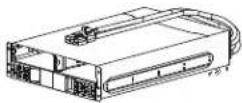 | Railkit with necessary hardware Safety  | Guide  |
Battery modules CAN bus communication  | end termination dongle  | XBP communication cable  |
Installation
Unpacking

CAUTION
RISK OF DROPPED OR FALLING EQUIPMENT
The equipment is heavy. Follow guidelines given in "Product Handling Guidelines" on page 5.
Failure to follow these instructions could result in equipment damage and minor or moderate injury.
UPS Frame
① Cut open the shipping straps with a general-purpose knife.
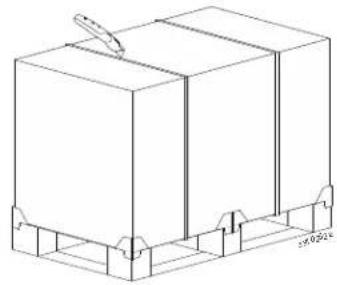
② Lift the carton off the pallet.

3 Remove the UPS railkit, Litkit and store them safely.

4 Remove the top packing cushions.

5 Lift the UPS frame off the pallet.

Battery Frame
1
Open the carton.

2
Remove the railkit, Litkit and store them safely.

3
Remove the top packing cushions.

4
Lift the battery frame out from the carton.

Install Frames in a 4 Post Rack

CAUTION
RISK OF DROPPED OR FALLING EQUIPMENT
- The equipment is heavy. Follow guidelines given in "Product Handling Guidelines" on page 5 for lifting and sliding the frame into the rack.
• Install power modules and battery modules only after the frame is installed in the rack. - Place the rack in the location where the equipment will be used.
- Do not move the rack once the frame is secured.
- Secure the frame in the rack before installing power modules and battery modules.
Failure to follow these instructions could result in equipment damage and minor or moderate injury.
Models with UPS frame only
1
Install the UPS rails (supplied) in the rack.
Be sure to align the bottom mounting holes on the rails to hole #1 (bottom hole) on the rack.
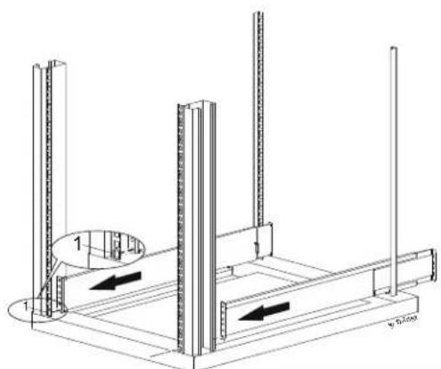
2 Secure the rails to the rack with 16 flat head screws and conical washers (supplied)
(NOTE: Tightening torque: 24 to 26 lb-in).
Utilize holes 1, 3, 4, and 5 on the front of the rails and all the 4 holes on the rear of the rails.

3 Install cage nuts in the rack.
The number indicated in the illustration is the position number counted from the bottom.

4 Install the UPS frame in the rack.
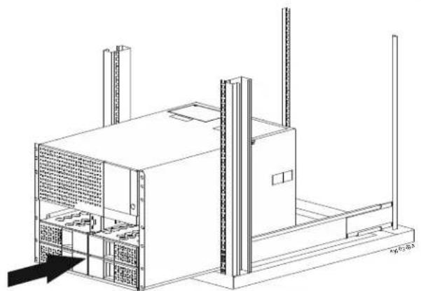
5 Secure the UPS frame to the rack. Use the 14 nos. ornamental screws supplied. NOTE: Tightening torque: 24 to 26 lb-in.

Models with both UPS and battery frames
Install battery frame rail (supplied) in the rack. Be sure to align the bottom mounting hole on the rails to hole #1 (bottom) on the rack.

Secure the battery frame rail to the rack with 12 flat head screws and conical washers (supplied). NOTE: Tightening torque: 24 to 26 lb-in. Utilize holes 2 and 4 on the front of the rails and all the 4 holes on the rear of the rails.

3 Install up to 3 nos. (on each rail) panhead screws with SEMs washer (supplied) to lock the rails in position.
NOTE: Install the panhead screws with SEMs at those locations where the tapped hole is visible through the slot in the rail.

4 Install UPS rail (supplied) in the rack.
Be sure to align the bottom mounting hole on the rails to hole #10 (from bottom) on the rack.

5 Secure the UPS rail to the rack with 16 flat head screws and conical washers (supplied).
NOTE: Tightening torque: 24 to 26 lb-in.
Utilize holes 1, 3, 4, and 5 on the front of the rails and all the 4 holes on the rear of the rails.
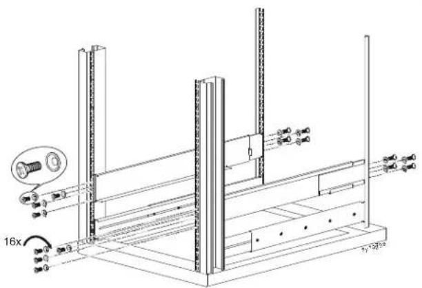
6 Install cage nuts in the rack.
The number indicated in the illustration is the position number counted from the bottom.

⑦ Install the battery frame in the rack.

8 Secure the battery frame to the rack. Use 6 nos. ornamental screws supplied.
NOTE: Tightening torque: 24 to 26 lb-in.

9 Install the UPS frame in the rack.

10 Secure the UPS frame to the rack. Use 14 nos. ornamental screws supplied.
NOTE: Tightening torque: 24 to 26 lb-in.

Install Frames in a 2 Post Rack
NOTE: The 2 post mounting brackets (SRYLOPT2 for mounting UPS Frame and SRYLOPT5 for mounting the XBP frame) are available as an accessory and should be procured separately.

CAUTION
RISK OF DROPPED OR FALLING EQUIPMENT
- The equipment is heavy. Follow guidelines given in "Product Handling Guidelines" on page 5 for lifting and sliding the frame into the rack.
• Install power modules and battery modules only after the frame is installed in the rack. - Place the rack in the location where the equipment will be used.
- Do not move the rack once the frame is secured.
- Secure the frame in the rack before installing power modules and battery modules.
Failure to follow these instructions could result in equipment damage and minor or moderate injury.
Models with UPS frame only
① Anchor the 2 post rack to the floor.

2 Install both the UPS frame lower brackets in the rack and secure them to the rack using 10 nos. screws (supplied).
NOTE: Tightening torque: 24 to 26 lb-in.
Be sure to align the bottom holes in the brackets to the 2nd hole from the bottom in the rack.

3 Install both the left and right UPS top brackets in the rack and secure them to the 4 nos. ornamental screws provided.
NOTE:
Tightening torque: 24 to 26 lb-in.
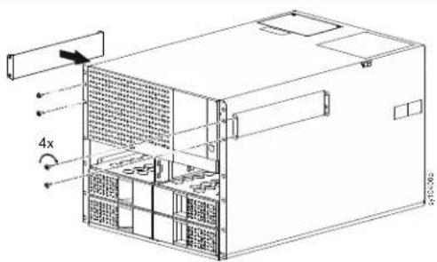
4 Install the UPS frame in the rack.

5 Secure the UPS frame to the left and right UPS frame lower brackets using 4 nos. ornamental screws (supplied).
NOTE:
Tightening torque: 24 to 26 lb-in.
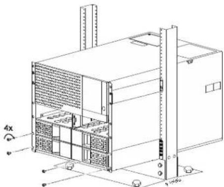
6 Secure the UPS frame upper brackets to the rack using 6 nos. screws (supplied).
NOTE: Tightening torque: 24 to 26 lb-in.

Models with both UPS and battery frames
① Anchor the 2 post rack to the floor.

② Install the battery frame bracket in the rack.
Be sure to align the bottom mounting holes on the bracket to hole #4 (from the bottom) on the rack.

③ Secure the battery frame brackets to the rack using 8 screws (2 on the front mounting tab and 2 on the rear mounting tab in each bracket).
NOTE: Tightening torque: 24 to 26 lb-in.

4 Install the battery frame in the rack.

5 Secure the battery frame to the bracket using 4 nos. ornamental screws (supplied).
NOTE:
Tightening torque: 24 to 26 lb-in.

6 Install both the UPS lower brackets in the rack and secure them to the 10 nos. screws provided.
NOTE: Tightening torque: 24 to 26 lb-in.

7 Install both the left and right UPS top brackets in the rack and secure them to the 4 nos. ornamental screws provided.
NOTE: Tightening torque: 24 to 26 lb-in.
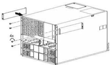
8 Install the UPS frame in the rack.

9 Secure the UPS frame to the left and right UPS lower brackets using 4 nos. ornamental screws supplied.
NOTE:
Tightening torque: 24 to 26 lb-in.

10 Secure the UPS frame upper brackets to the rack using 6 nos. screws (supplied). NOTE: Tightening torque: 24 to 26 lb-in.

Install Power Module(s) and Battery Module(s)

CAUTION
RISK OF DROPPED OR FALLING EQUIPMENT
- The equipment is heavy. The approximate weight of the power module is 9.4 kg (20.72 lb) and that of the battery module is 10 kg (22 lb).
- Follow guidelines given in "Product Handling Guidelines" on page 5.
- Be sure to hold the module with both hands during installation.
- Do not use the finger hold to lift or carry the module.
• Install Power Module(s) in the UPS frame only.
Failure to follow these instructions could result in equipment damage and minor or moderate injury.
NOTE: The installation procedure is the same for both the power module and the battery module. A power module is used for illustrating the instructions.
- Power modules and battery modules can be installed in any of the 6 slots in the UPS frame.
- Only battery modules can be installed in the battery frame.
- Remove the blanking panels, if required, in the UPS frame or the battery frame to install the modules. Refer "Remove Blanking Panels" on page 25 for details.
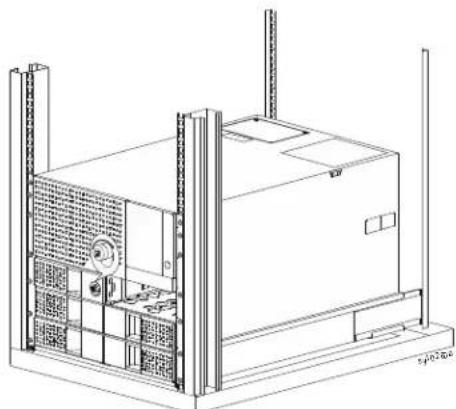
1
a. Orient the module so the thumbscrew is towards the middle of the frame. b. Slide in the module until the latch engages.

2
Hand tighten the thumbscrew to enable the module and lock the latch.
Remove Blanking Panels
| 1 | Insert a slotted screwdriver into the slot on the blanking panel. |  |
| 2 | Push the screw driver gently into the slot till a resistance is felt, and pull out the blanking panel using the finger grip. |
Remove Power Module and Battery Module

CAUTION
RISK OF DROPPED OR FALLING EQUIPMENT
- The equipment is heavy. The approximate weight of the power module is 9.4 kg (20.72 lb) and that of the battery module is 10 kg (22 lb).
- Follow guidelines given in "Product Handling Guidelines" on page 5.
- Be sure to hold the module with both hands during removal.
- Do not use the finger hold to lift or carry the module.
Failure to follow these instructions could result in equipment damage and minor or moderate injury.
NOTE: The removal procedure is the same for both power module and battery module. A power module is used for illustrating the instructions except in step 1.
NOTE: Before removing a power module, be sure that the connected load is well within the capacity of the remaining power modules. If not, disconnect some of the non-essential loads before removing a power module.
① Turn off the battery module by setting the BATTERY ON/OFF switch to OFF. NOTE: This step is applicable only for battery module.
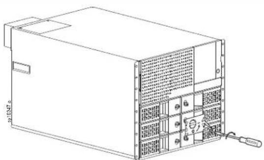
2 Loosen the thumbscrew to disable the module and unlock the latch.


To release the latch:
- Left module: Slide the thumbscrew downwards.
• Right module: Slide the thumbscrew upwards.


a. Release the latch and pull the finger hold on the front face of the module until the latch clears the frame.
NOTE: Do not use the finger hold to pull the module completely from the frame.
b. Support the module with both hands and pull out the module completely from the frame.

Rear Panel Features
UPS Frame

| A | SmartSlot | J | USB port |
| B | UPS battery connector | K | XBP communication portNOTE: Insert the CAN buscommunication end terminationdongle when an XBP is not installed. |
| C | Hardwire access (knockout) for output | ||
| D | Hardwire access (knockout) for input | ||
| E | Input/Output wiring tray | ||
| F | PDU cover plate | L | SYSTEM/INVERTER ENABLE switch |
| G | Universal I/O port | M | Service bypass unit signal port |
| H | Modbus portNOTE: Terminate 150 ohm resistors(supplied) at each end of the buswhen bus length is greater than2000 ft when operating at 9600 baudor 1000 ft when operating at19200 baud. | N | EPO port |
| P | Ethernet port | ||
Battery Frame

| A | XBP Status indicator | C | Communication port |
| B | FRAME# SETTING switch | D | Battery connector |
Front Panel Features
UPS
View after removing the front bezel
NOTE: Ⓐ and Ⓑ can be accessed only after removing the front bezel.

| A | MANUAL BYPASS switch | F | Power module |
| B | Front Bezel | G | Thumbscrew |
| C | Hardwire terminal inspection cover | H | Battery module |
| D | LCD display | J | BATTERY ON/OFF switch |
| E | POWER ON buttonNOTE: refer to “Turn on without Utility Power” on page 42 for details. | K | Intelligence modulesNOTE: Do not remove both Intelligence Modules from the UPS frame at the same time. The UPS will drop the connected load. |
Hardwiring

CAUTION
RISK OF ELECTRIC SHOCK
- Hardwiring must be performed by a qualified electrician or service personnel. - Adhere to all national and local electrical codes.
Failure to follow these instructions could result in equipment damage and minor or moderate injury.
NOTE: UPS with 125 A Input/Output wiring tray is used for illustration purposes. The instructions remain the same for UPS frame with 125 A Input/Output wiring tray and UPS with 100 A Input/Output wiring tray.
① Remove the knockouts.
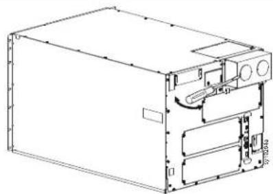
2 Locate the screws securing the Input/Output wiring tray to the UPS frame and unfasten them.
NOTE: 2 screws secure the 100 A Input/Output wiring tray and 3 screws secure the 125 A Input/Output wiring tray.
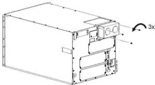
3 Remove the Input/Output wiring tray.

4 Install appropriate strain relief (not supplied) for input power wiring and output power wiring.
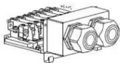
5 Insert the wires through the strain relief.

6 Secure the wires to the terminal block. Refer "Terminal Configuration" on page 30 for connection details.
NOTE: Minimum tightening torque - 4.5 N m.
⑦ Install the wired Input/Output wiring tray.

⑧ Secure the Input/Output wiring tray to the UPS frame using the screws removed in step ②.

Terminal Configuration

Connect Battery Frame

CAUTION
RISK OF ELECTRIC SHOCK
Battery frame installation must be performed by a qualified electrician or service personnel.
Failure to follow these instructions could result in equipment damage and minor or moderate injury.
Connect a single battery frame to UPS
① Locate the screw securing the UPS battery connector cover to the UPS frame and unfasten it.

② Remove the UPS battery connector cover.

3 Insert the XBP power cable connector into the UPS battery connector.
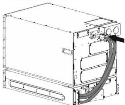
4 Tighten the thumbscrew to secure the XBP power cable connector to the UPS battery connector.

| 5 | Set a unique identification (ID) number on the FRAME# SETTING switch (refer “Battery Frame” on page 28 for identifying the switch).The position of the notch on the dial indicates the set unique ID number. |
| 6 | Connect the XBP communication cable between the XBP communication port on the UPS frame and the communication port on the battery frame. |
| 7 | Connect the CAN bus communication end termination dongle to the free communication port on the battery frame. |
NOTE: The XBP status LED illuminates green when communication with the UPS is established. Otherwise XBP status LED illuminates red.
Connect multiple battery frames to UPS
| 1 | Connect the first battery frame to the UPS. Follow steps 1 to 6 in “Connect a single battery frame to UPS” on page 31. |
| 2 | Locate the screw securing the battery connector cover to the battery frame (Battery Frame#1) and unfasten it. |
| 3 | Remove the battery connector cover in Battery Frame#1. |
| 4 | Insert the XBP power cable connector of battery frame#2 into the battery connector in Battery Frame#1. |
5 Tighten the thumbscrew to secure the XBP power cable connector of Battery Frame#2 to the battery connector in Battery Frame#1.

6 Set a unique identification (ID) number on each Battery Frame connected on the FRAME# SETTING switch (refer "Rear Panel Features" on page 27 for identifying the switch).
The position of the notch on the dial indicates the set unique ID number.
NOTE: Set a unique ID for each battery frame connected.
7 Connect the communication cable between the free communication ports on Battery Frame#1 and Battery Frame#2.
8 Connect the CAN bus communication end termination dongle to the free communication port on the Battery Frame#2.
NOTE: The CAN bus communication end termination dongle should be connected to the free communication port on the last Battery Frame connected.
NOTE: The XBP status LED illuminates green when communication with the UPS is established. Otherwise XBP status LED illuminates red.
Battery Cable Extension
A battery cable extension (SRYLOPT8) is available as an accessory (separate purchase) to connect battery frames to the UPS frame (or another battery frame) housed in different racks. The extension cable is 8 ft (2.43 m) long.
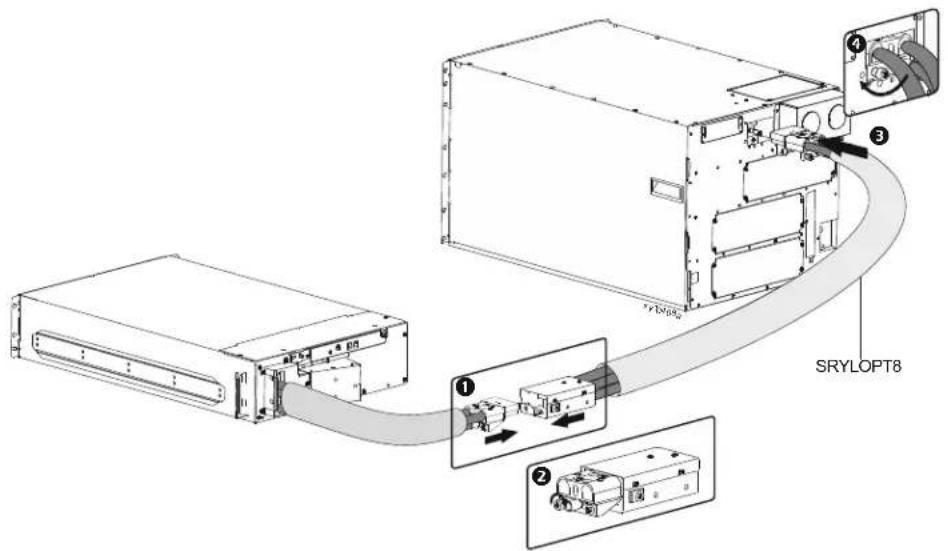
Insert the XBP power cable connector into the battery connector in the battery cable extension (SRYLOPT8).
② Tighten the thumbscrew to secure the XBP power cable connector to the battery connector in the battery cable extension.
Insert the power cable connector in the battery extension cable into the UPS battery connector.
4 Tighten the thumbscrew to secure the battery extension cable connector to the UPS battery connector.
5 Connect the XBP communication cable (supplied along with the battery cable extension) between the XBP communication port on the UPS frame and the communication port on the battery frame.
Operation
Modes
On-line
The UPS supplies conditioned utility power to the connected equipment.
![graph LR A["Input Rectifier"] --> B["Inverter"] B --> C["Battery"] C --> D["Output"] D --> E["Green / Bypass"] E --> B](/content/2026/05/1083312/images/cc6e60473e911a37a498ec043aa254f967a5143d970852e45767b0019a1156fd.jpg)
On-battery
The UPS supplies conditioned battery power to the connected equipment.
![graph LR A["Input Rectifier Inverter"] --> B["Battery"] B --> C["Green / Bypass"] C --> D["Output"] style A fill:#f9f,stroke:#333 style B fill:#ccf,stroke:#333 style C fill:#cfc,stroke:#333 style D fill:#fcc,stroke:#333](/content/2026/05/1083312/images/4d3905c2e0ff45a447b746bf0299db9af79baa929ee968f73bd1ac48ea70bdd7.jpg)
NOTE: The UPS transfers to On-battery mode when the load on the UPS is 100% and the input voltage is above 150 V or below 95 V.
Green
The UPS supplies utility power directly (without conditioning) to the connected equipment.
In the event of a brown-out or a black-out, there will be an interruption in power to the connected equipment (up to 10 ms) while the system switches to Online mode or On-Battery mode.
When enabling Green mode, consideration should be given to devices that may be highly sensitive to power fluctuations.
![graph LR A["Input"] --> B["Rectifier"] B --> C["Inverter"] C --> D["Output"] E["Battery"] --> B F["Green / Bypass"] --> C](/content/2026/05/1083312/images/f6eef38ba5653c4b8ce5321ca8fd3b66ce87d90143e6b9221637f2474098a24f.jpg)
Bypass Mode
In Bypass mode, unconditioned utility power is directly supplied to the connected equipment.
![graph LR A["Input Rectifier Inverter"] --> B["Green / Bypass"] B --> C["Output"] D["Battery"] --> E["Logic Gate"] E --> F["Output"] G["Diode"] --> H["Green / Bypass"] H --> I["Output"]](/content/2026/05/1083312/images/121bdcaf5bed9c17e8aff97056ab622238ca55f7f32521121be3d5df33a8ee96.jpg)
Temporary Bypass
When a temporary phenomenon, like the connected load being greater than the UPS rating but lesser than the utility power circuit breaker rating, the UPS goes into temporary bypass. The UPS comes back to on-line or on-battery mode automatically once the temporary phenomenon gets corrected, like non-essential loads being disconnected from the UPS. The UPS will not transfer to on-battery mode until the temporary phenomenon is corrected.
When the UPS is operating in this mode, the UPS status information will change to "Temp Bypass".
Command Bypass
The user can intentionally command the UPS to operate in bypass mode through the LCD display (Home → Control → UPS → Put UPS in Bypass).
The UPS will operate in this mode as long as the utility power voltage is within the configured upper and lower voltage limits. Refer to "Bypass Setting" on page 55 for details.
The UPS will transfer to on-battery mode if the utility power voltage is not within the configured limit or in the event of a black out.
When the UPS is operating in this mode, the UPS status information will change to "Software Bypass".
Manual Bypass
To go into this mode, set the MANUAL BYPASS switch to ON. The UPS transfers to internal maintenance bypass operation.
Refer to "Set the UPS to Manual Bypass Mode" on page 38 for instructions to set the UPS to this mode.
The UPS will operate in this mode as long as the MANUAL BYPASS switch is set to ON. To get the UPS back to on-line or on-battery mode, set the MANUAL BYPASS switch to OFF.
The UPS will not transfer to on-battery mode till the MANUAL BYPASS switch is set to OFF.
When the UPS is operating in this mode, the UPS status information will change to "Manual Bypass".
Event Bypass
The UPS goes into Event Bypass and supplies unconditioned utility power directly to the connected equipment when the PMs cannot support the connected load.
![graph LR A["Input Rectifier Inverter"] --> B["Green / Bypass"] B --> C["Output"] D["Battery"] --> E["Logic Gate"] E --> F["Green / Bypass"] F --> G["Output"]](/content/2026/05/1083312/images/1cdd00c9e5e26fbe948b4dcd39b3441602dabde1a61520150834c501321d5da3.jpg)
When the UPS transfers to this mode, the UPS status information will change to "Fault Bypass".
Contact customer support when the UPS transfers to this mode.
Standby Mode with AC Present
In this mode, the output is turned off and the internal systems and the battery charger are powered by the utility power.
![graph LR A["Input Rectifier Inverter"] --> B["Battery"] B --> C["Green / Bypass"] C --> D["Output"] style A fill:#000,stroke:#fff,color:#fff style B fill:#000,stroke:#fff,color:#fff style C fill:#000,stroke:#fff,color:#fff style D fill:#000,stroke:#fff,color:#fff](/content/2026/05/1083312/images/36f3274209c0370a0c851019559cd7f7ec75b5fd96a3f75f4f876c66998cf184.jpg)
Standby Mode with AC Not Present
In this mode, the output is turned off and the internal systems are powered by the battery.
![graph LR A["Input Rectifier Inverter"] --> B["Green / Bypass"] B --> C["Battery"] C --> D["Output"] style A fill:#f9f,stroke:#333 style B fill:#ccf,stroke:#333 style C fill:#cfc,stroke:#333 style D fill:#fcc,stroke:#333](/content/2026/05/1083312/images/06ae00fe718ef5842cc2cf373da4aeb608330ea6a7bd6ca8e7d682c4d70de062.jpg)
System Alarm
In this mode, the UPS output is turned off and the internal systems are powered by the battery, irrespective of whether utility power is available or not. Contact customer support to resolve the detected error.
![graph LR A["Input Rectifier Inverter"] --> B["Battery"] B --> C["Green / Bypass"] C --> D["Output"] style A fill:#f9f,stroke:#333 style B fill:#ccf,stroke:#333 style C fill:#cfc,stroke:#333 style D fill:#fcc,stroke:#333](/content/2026/05/1083312/images/f30d61e8e1fed457facf83af052c96d61ba544ff8610a08654097ed2557559ee.jpg)
When the UPS goes into this mode, the LCD display screen will be illuminated red.

Set the UPS to Manual Bypass Mode
Command the UPS to operate in bypass mode (command bypass) through the LCD display (Home → Control → UPS → Put UPS in Bypass).
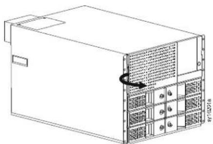
② Open the front bezel.
Remove the front bezel from its housing.

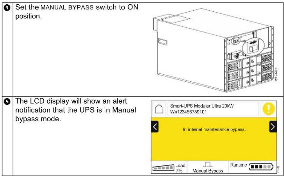
Set the MANUAL BYPASS switch to OFF to bring the UPS out of the manual bypass mode.
The UPS goes into temporary bypass mode for a short time and then returns to the state in which it was operating prior to setting it to manual bypass mode.
One Line Diagram Status Indicators
| Function LED Illumination Description | |||
 | Input Green Utility power is present and is within normal operating range. | ||
 | Rectifier Green Rectifier circuit is active. | ||
 | Bypass Green Green function is active. | ||
 | Battery Green Battery is available and is fully charged or charging. | ||
 | Inverter Green Inverter circuit is active. | ||
 | Output Green Power is being supplied to the connected load from the UPS. | ||
Status LEDs

| A | System Status LED |
| B | Module Status LEDs |
| C | Power ON button LED |
| Status LED Color $status | |
| System Status - (behind the bezel) reflects system status and matches the background color of the LCD display. | |
| Not illuminated UPS | is not powered on. |
| Illuminates Green UPS | is operating normally. |
| Illuminates Amber UPS | is experiencing an alarm condition or operating on battery. |
| Illuminates Red UPS | has detected an internal error. |
| Module Status represents the status of battery/power module. Check LCD display for details. | |
| Not illuminated Module | is not powered. |
| Blinks Green Status | LEDs blink every second when power module is in standby state.NOTE: This is applicable only for power module. |
| Illuminates Green Module | is operating normally. |
| Illuminates Amber Module | module is operating but an alarm condition exists.(On-battery state is also an alarm since the battery is discharging.) |
| Illuminates Red Module | not available due to a detected internal error. |
| Power ON button LED. | |
| Not illuminated UPS | output is OFF. |
| Illuminates Green UPS | output is ON. |
Start Up

CAUTION
RISK OF ELECTRIC SHOCK
- Set the utility power circuit breaker to OFF before installing or servicing the UPS.
- Disconnect BMs and XBPs before installing or servicing the UPS.
- The UPS contains BMs and XBPs that may present a shock hazard even when disconnected from the utility power.
- UPS AC hardwired and pluggable outlets may be energized by remote or automatic control at any time.
- Disconnect equipment from the UPS before servicing any equipment.
- Do not use the UPS as a safety disconnect.
- Use strain reliefs.
- Recommended input terminal screw torque: 40 lbf-in (4.5 Nm).
Failure to follow these instructions can result in equipment damage and minor or moderate injury.
NOTE: The UPS batteries will charge to 90% capacity in the first three hours of normal operation. Do not expect full battery runtime capability during this initial charge period.
- Hardware the equipment to the Output Hardwire terminals in the UPS or connect the equipment to the outlets on the rear panel of the UPS, if PDUs are installed.
- Set the BATTERY ON/OFF switch to ON.
- Connect the UPS to the building utility power.
- Be sure that the SYSTEM/INVERTER ENABLE switch located on the rear panel of the UPS is set to ON.
Turn on / Turn off the UPS
The first time the UPS is turned on, the Setup Wizard screen will run. Follow the on-screen prompts to configure UPS settings. Refer to "UPS Menu Overview" on page 48 for details.
Tum on
UPS goes to standby mode when utility voltage is applied at the AC input terminals. The LCD display illuminates and displays an Initializing screen, indicating that the system is getting initialized. This process takes approximately 1 minute. After successful initialization, user menus will be available on the LCD display.
To turn on the UPS output and supply power to the connected equipment:
- Touch the Home icon on the LCD display to access the Main menu.
- Touch the Control option.
- Touch the UPS option.
- Touch Turn UPS on. To turn on the UPS output immediately enable Skip UPS On Delay. To turn on the UPS output after the configured time delay, disable Skip UPS On Delay.
- Touch the OK button.
- Output will get turned on.
Turn on without Utility Power
UPS can be turned on without the building utility power, through cold start.
To cold start the UPS, press the POWER ON button. Refer to "Front Panel Features" on page 28 for locating the POWER ON button.
This powers on the battery module(s) and wakes up the UPS. LCD display will turn on, displaying an Initializing screen, indicating that the system is getting initialized. This process takes approximately 1 minute. After successful initialization, user menus will be available on the LCD display.
To turn the output on and supply power to connected load:
- Touch the Home icon on the LCD display to access the Main menu.
- Touch the Control option.
- Touch the UPS option.
- Touch the Turn UPS On without AC
- Touch the OK button.
- Output will get turned on.
Tum off
To turn off the output power:
- Touch the Home icon on the LCD display.
- Touch the Control option.
- Touch the UPS option.
-
Touch Turn UPS off.
To turn off the UPS output immediately, enable Skip UPS Off Delay. To turn off the UPS output after the configured time delay, disable Skip UPS Off Delay. -
Touch the OK button.
The UPS will continue to operate in standby mode, even after the output is turned off.
To completely turn off the UPS, disconnect the UPS from the utility power. The UPS will now continue to operate in standby mode, on battery power for approximately Ten (10) minutes, or until the battery charge gets depleted completely, whichever is earlier.
To completely turn off the UPS (without allowing it to operate in standby mode), on the LCD display:
- Select the Home icon.
- Select the Control option.
- Select the UPS option.
- Select the Internal Power Off option.
- Touch the OK button.
The UPS will turn off completely.
LCD Display
NOTE: The LCD display screens may differ slightly on your unit.

| A | HOME icon Refer to UPS Network ManagementCard 3 User Guide", for details of the below features, . | |
| B | Notification icon | |
| C | Access door to front ports - H, J, K, L, and M | Status LED |
| Link RX/TX (10/100/1000) LED | ||
| D | Output status LED | USB port |
| E | POWER ON button | Console port |
| F | One line diagram | RESET button |
| G | UPS status information | |
Operating the LCD Display
• The LCD display is a touchscreen interface.
- Touch an icon to activate the button.


- Use the "<" and "> " to scroll through the screens and "∧" and "∨" to scroll through the options.
- A keypad will pop-up to update fields that require values to be entered.
- Touch the OK button to accept the selected option.
NOTE: The OK button gets enabled only when a setting is changed. Otherwise, the button will be in disabled state.
- Touch the ESC button to return to the previous menu or
- Select the menu option you would like to return to.
NOTE: Use a dry microfiber (non-abrasive) cloth to clean the LCD display.
UPS Status Screen (Home Screen)

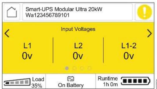
The status screen field provides key information on the UPS.
The menu will scroll through four screens automatically:
- Input Voltages
- Output Voltages
- Input/Output Frequency
- Output Power
The bottom of each screen will display the percentage of rated load the UPS is powering, the operating mode of the UPS, and the remaining runtime on battery.
The Notification icon is located on the top right corner of each screen, and the Home icon is located on the top left corner.
In case of an UPS event, status updates will be displayed, defining the event or the condition that has occurred. The LCD display screen illuminates amber to indicate an alert and red to indicate an alarm depending on the severity of the event or condition.


Typical Alert/Notification/Alarm Screens
On-battery alert

On-battery alert
(Home Screen - page 1)
Output Off information
(Home Screen - page 2)

Low battery alarm (page 1)

Low battery alarm (page 2)

Icons
The icons on the LCD display screen may vary depending on the installed firmware version.
| Load icon: The approximate load capacity percentage is indicated by the number of illuminated load bar sections. Each bar represents approximately 16% of the load capacity. | |
| Mute icon: Indicates the audible alarm is disabled/muted. | |
| Home icon:• Touch this icon on any screen to return to the Home screen.• Touch this icon, on the Home screen, to activate the Main Menu screen. |
Operation Mode Icons
| On-Line mode: The UPS is supplying conditioned utility power to connected equipment. | |
| Bypass mode: In Bypass mode, unconditioned utility power is directly supplied to the connected equipment. | |
| Green mode: In Green mode, the UPS will supply conditioned utility power to the connected equipment.In the event of a utility power outage or brown out, there will be an interruption in power to the connected equipment (up to 10 ms) while the UPS switches to On-Line mode or Battery mode.When enabling Green mode, consideration should be given to devices that may be sensitive to power fluctuations. | |
| Battery mode: The UPS is supplying battery power to connected equipment. | |
| UPS output off: The UPS is not supplying power to the connected equipment. |
Notification Icons
| Normal: UPS is functioning normally and no alarms or events exist. | |
| Information: UPS status information is available. | |
| Alert: UPS has detected an alert condition. | |
| Alarm: UPS has detected an alarm condition. |
Battery Status Icons
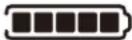 | Battery Charge Status: Indicates the battery charge status. Each illuminated bar represents approximately 16% charge. |
Main Menu Screen
Touch the Home icon, on the Home Screen, to activate the Menu screen.

UPS Menu Overview
Main Menu
Status
Control
Configuration
Tests
Log
About
Login (Optional)
Status
UPS
Active Alarms
UPS
System
Input
Output
Overview
Battery Modules
System
UPS Status
Runtime Remaining, State of Charge, Battery Voltage
Current Redundancy
Min. Battery Cell Voltage, Max. Battery Cell Voltage
Min. Battery Temperature, Max. Battery Temperature
Input
Voltage : L1, L2, L1-L2
Frequency
Output
Voltage : L1, L2, L1-L2
Frequency
Current : L1, L2
Apparent Power : L1, L2
Real Power : L1, L2
Total Power
Energy : L1, L2
Total Energy
Power Factor : L1, L2
Efficiency
Overview*
Battery Modules
Location
Status
Health
Replace By (Date)
Active Alarms**
UPS
Turn UPS On / Turn UPS Off
Reboot UPS
Put UPS to Sleep
Put UPS in Bypass
Clear Alarms
Skip UPS Off Delay / Skip UPS On Delay
Display
Restart Display / Network Interface
A
* Navigate Home → Overview to view the information.
** Touch any of the Notification icons to view the Active Alarms screen on the LCD display. Refer to "UPS Status Screen (Home Screen)" on page 44 for sample alarm screens.
56103048
![graph TD A["Configuration"] --> B["UPS"] A --> C["Display"] A --> D["Network"] A --> E["Date and Time"] A --> F["Restore Defaults"] A --> G["USB Storage"] H["UPS"] --> I["Output: Rated Voltage, Frequency Range, Frequency Slew Rate Green Mode Enable/Disable L-N Lower Limit (V), L-L Lower Limit (V) L-…](/content/2026/05/1083312/images/466fd3961a67af91ccc6344959b0324394aa832ab11a3c0b4f7be1809a63e19a.jpg)
ay10335a
![graph TD A["A"] --> B["Tests"] A --> C["Logs"] A --> D["About"] D --> E["UPS"] D --> F["Display Network"] D --> G["Display"] G --> H["Network"] B --> I["UPS Self Test\nUPS Alarm Test\nUPS Alarm Test - Continuous"] C --> J["UPS Log\nNMC Log"] E --> K["UPS System: Model, SKU, Serial Number, Manufactur…](/content/2026/05/1083312/images/77483920889d80baef7b3c8a036c94ab0cd0dd6c389fcc098d7140fe132f8f95.jpg)
Configuration
There are three ways to select UPS configuration options.
-
The first time the UPS is turned on, the Setup Wizard screen will open. On each menu screen select the desired settings. Touch the OK button after selecting each setting.
The UPS will not turn on until the setup is completed. -
Main Menu → Configuration → UPS → Default Setting. This screen allows the user to reset the UPS to factory (default) settings. Touch the OK button after selecting the UPS setting.
Refer to "UPS Menu Overview" on page 48 for details.
- Configure settings using an external interface, such as the Network Management Web interface.
Startup configuration
NOTE: The configuration menu options vary according to the UPS models.
1. Set the language of LCD display
Options:
- English
- French
- Italian
- German
- Spanish
- Portuguese
- Japanese
- Russian
- Chinese
- Korean

2. Set Output Voltage
Options:
• 120/208 VAC
- 120/240 VAC

3. Set Alarm if Redundancy Under
Select the number of redundant power modules. If the number (of redundant power modules) falls below the set value, then the UPS will initiate an alarm.
Options:
- Never
• N + 1
• N + 2

4. Set Time Zone, Current Date, and Time
NOTE: This is the NMC's Time Zone, Date, and Time settings. If the NTP (Network Time Protocol) is enabled in the NMC, then this screen will not appear on the LCD display.

5. Set Installation Date
NOTE: If the Installation date is already set in the UPS, this screen will not appear on the LCD display.

General settings
Configure these settings at any time, using the LCD display or the Network Management Web Interface.
The settings can be done in the following ways:
- Using the "A" and "V" buttons to navigate through the options available.
• Using the keypad, which pops up when a value field is touched. - Touch the Check Box to either enable (checked) or disable (unchecked) it.
1. Output settings
(Home → Configuration → UPS → Output)


a. Rated Voltage
Set the output voltage for the UPS. This setting can only be changed when the UPS output is off.
Default Value: The value should be selected by the user during the initial startup. Reset to factory default does not change the selected value.
Options:
- XLT models:
-120/208 V
-120/240 V
b. Frequency Range
Set the output frequency for the UPS.
Default Value: Auto 50/60 ± 3Hz
Options:
• Auto 50/60 ± 3 Hz
- 50 ± 0.1 Hz
- 50 ± 3.0 Hz
- 60 ± 0.1 Hz
- 60 ± 3.0 Hz
c. Frequency Slew Rate
Select the rate of change of the output frequency in Hz per second.
Default Value: 1 Hz/sec
Options:
- 1 Hz/sec
- 2 Hz/sec
- 4 Hz/sec
d. Green Mode
Disable or enable Green mode operation.
Default Value: Disable
Options:
- Disable (unchecked "Enable")
- Enable
e. Output Lower Acceptable Voltage
If the UPS input voltage is between the lower acceptable voltage and the higher acceptable voltage, the UPS will operate in Green mode.
If the output voltage goes outside the acceptable range, the UPS will switch from Green mode to On-line mode or to On-battery mode.
L-N Lower Limit:
Default Value: 120/208 V output: 106 V
120/240 V output: 106 V
Options: 120/208 V output: 97 to 106 V
120/240 V output: 97 to 106 V
L-L Lower Limit:
Default Value: 120/208 V output: 184 V
120/240 V output: 212 V
Options: 120/208 V output: 168 to 184 V
120/240 V output: 194 to 212 V
f. Output Upper Acceptable Voltage
If the UPS input voltage is between the lower acceptable voltage and the higher acceptable voltage, the UPS will operate in Green mode.
If the output voltage goes outside the acceptable range, the UPS will switch from Green mode to On-line mode or to On-battery mode.
L-N Upper Limit:
Default Value: 120/208 V output: 127 V
120/240 V output: 127 V
Options: 120/208 V output: 127 to 136 V
120/240 V output: 127 to 136 V
L-Line Upper Limit:
Default Value: 120/208 V output: 220 V
120/240 V output: 254 V
Options: 120/208 V output: 220 to 236 V
120/240 V output: 254 to 272 V
2. Bypass Setting
(Home → Configuration → UPS → Bypass)

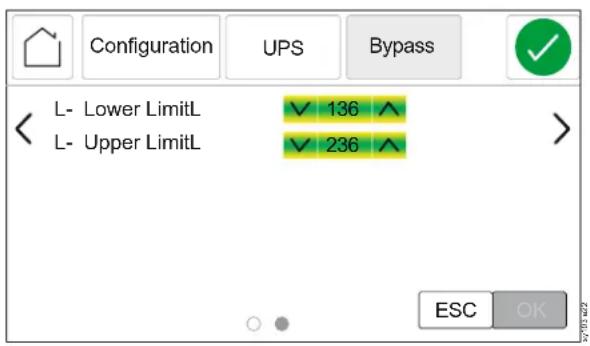
a. Bypass Allowed
"Phase Lock" refers to the condition where the input frequency matches the configured output frequency.
"Phase Lock Required" will only allow the UPS to enter Bypass/Green Mode under normal conditions where input frequency is equal to output frequency.
"Never Acceptable" will prevent the UPS from going into bypass mode during normal operation.
"Always Acceptable" will allow the UPS, when it is operating normally, to transfer to bypass mode as long as the input voltage is within configured limits.
Default Value: Phase Lock Not Required
Options:
• Phase Lock Not Required
- Phase Lock Required
- Never Acceptable
• Always Acceptable
b. Bypass L-N Acceptable Voltage
If the UPS input voltage is between the lower acceptable voltage and the higher acceptable voltage, the UPS will operate in Bypass mode.
Default Value:
Lower Limit: 120/208 V output: 97 V 120/240 V output: 97 V
Upper Limit: 120/208 V output: 136 V
120/240 V output: 136 V
Options:
Lower Limit: 120/208 V output: 92 to 106 V
120/240 V output: 92 to 106 V
Upper Limit: 120/208 V output: 127 to 148 V
120/240 V output: 127 to 148 V
c. Bypass L-L Acceptable Voltage
If the UPS input voltage is between the lower acceptable voltage and the higher acceptable voltage, the UPS will operate in Bypass mode, when enabled.
Default Value:
Lower Limit: 120/208 V output: 168 V 120/240 V output: 194 V
Upper Limit: 120/208 V output: 236 V 120/240 V output: 272 V
Options:
Lower Limit: 120/208 V output: 160 to 184 V
120/240 V output: 184 to 212 V
Upper Limit: 120/208 V output: 216 to 256 V
120/240 V output: 254 to 296 V
3. Timers setting
(Home → Configuration → UPS → Timers)
![Configuration UPS Timers Power Off Delay 90 s [0 - 32767] Reboot Duration 8 s [4 - 300] Power On Delay 256 s [0 - 600] Min Return Runtime 50 s [0 - 32767] ESC OK](/content/2026/05/1083312/images/0f9d7b028f6aaca6818e7f74df2b730fec2a6db9201228f0e82b6e3b0fb1e679.jpg)
a. Power Off Delay
Set the time delay for the UPS output to turn off after receiving the Turn UPS Off command.
Default: 90 seconds
Options: 0 to 32767 seconds
b. Reboot Duration
Set the time delay for the UPS to shut down after receiving the Reboot UPS command.
Default: 8 seconds
Options: 4 to 300 seconds
c. Power On Delay
Set the time delay for the UPS output to turn on after receiving the Turn UPS On command.
Default: 0 seconds
Options: 0 to 600 seconds
d. Min. Return Runtime
Set the minimum duration of battery runtime that must be available for the UPS output to turn on using battery power after a shutdown.
Default: 0 seconds
Options: 0 to 32767 seconds
4. Alarms setting
(Home → Configuration → UPS → Alarms)
![Configuration UPS Alarms Low Runtime s [120 - 3600] 3600 Redundancy ✓ Never ^ Battery Alarm Warning 183 d [-1 - 730] Battery Alarm Sleep 14 d [-1 - 365] ESC OK](/content/2026/05/1083312/images/58e3eca05a7fa7e765fa0282228b6b88c66a6ebc19ff672f91bb150631ee4d1a.jpg)
a. Low Runtime
Set runtime remaining threshold, when the UPS should emit an audible alarm.
Default Value: 150 seconds
Options: 120 to 3600 seconds
b. Redundancy
Set the number of redundant power modules. If the number (of redundant power modules) falls below the set value, then the UPS will initiate an alarm.
Default Value: Never
Options:
- Never
- N + 1
- N + 2
c. Battery Alarm Warning
Set the number of days prior to the estimated Battery EOL (End-of-Life), to receive an alert. When this date is reached, the UPS will emit an audible alarm and a message will appear on the LCD display screen.
Example: Using the default value, the Battery Alarm Warning will occur 183 days before the estimated EOL date.
To disable the notification/alarm, select -1.
Default Value: 183 days
Options:
• 0 to 730 days
• -1
d. Battery Alarm Sleep
The Battery Alarm Warning can be muted. Set the number of days for the next Battery Alarm Warning since it was muted.
To disable the notification, select -1.
Default Value: 14 days
Options:
• 0 to 365 days
• -1
5. General Settings
(Home → Configuration → UPS → General)

a. UPS Name
Set the name of the UPS.
NOTE: This value needs to be entered by the user (no default value or options for this setting).
b. Self-Test Schedule
Set the interval at which the UPS should execute a Self-test.
Default: Startup + 7 days since last test
Options:
- Never
- On Startup
- Startup + 14 days since last test
- Startup + 7 days since last test
c. Battery Replaced On
Set the date on which the battery module was last replaced.
NOTE: This value needs to be entered by the user (no default value or options for this setting).
6. Load Shedding setting
(Home → Configuration → UPS → Load Shedding)
NOTE: The UPS can be configured to shed the connected load (Load Shedding) by turning off the output, while operating in On-battery mode, based on:
- The time duration the UPS is On Battery mode ("Time on Battery") or
- The battery runtime remaining ("Runtime Remaining") or
- Both of the above
![UPS Load Shedding Time On Battery Enable Time On Battery 1000 s [5 - 32767] Runtime Remaining Enable Runtime Remaining 50 s [5 - 3600] ESC OK](/content/2026/05/1083312/images/24ec7cbb59c2b04129ef9b7c652dc53ef2d71ba17d6c1fa92cd6187d1690f731.jpg)
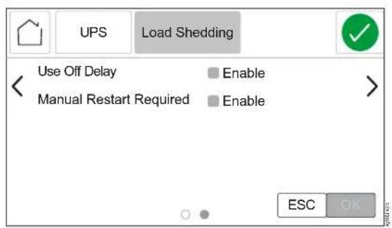
a. Time On Battery
Enable this feature to set the time duration for which the UPS supplies battery power to the connected load before load shedding.
Default: Disable
Options:
- Enable
- Disable (unchecked Enable)
b. Time On Battery
NOTE: This feature will be enabled only when the Time On Battery is set to Enable. Set the time duration for which the UPS supplies battery power to the connected load before load shedding.
Default: 32767 seconds
Options: 5 to 32767 seconds
c. Runtime Remaining
To conserve battery power, the UPS can turn off the output when the runtime remaining threshold is reached.
Default: Disable
Options:
- Enable
- Disable (unchecked Enable)
d. Runtime Remaining
NOTE: This feature will be enabled only when the Remaining Runtime is set to Enable.
Set the runtime threshold when the UPS will turn off the output.
Default: 0 seconds
Options: 0 to 3600 seconds
e. Use Off Delay
Enable this option for turning off the UPS output after the Power Off Delay time set, once the load shedding threshold is met when the UPS is On-battery mode. Refer to "Timers setting" on page 57,
Default: Enable
Options:
- Enable
- Disable (Unchecked "Enable")
f. Manual Restart Required
Enable this option to manually restart the UPS after the UPS output was turned off due to load shedding while operating in On-battery mode.
The UPS output gets turned off once the load shedding threshold is reached while the UPS is in On-battery mode. After the utility power is restored, the UPS goes into Standby with AC mode and remains in that mode till the UPS is manually restarted.
Default: Enable
Options:
- Enable
- Disable (Unchecked "Enable")
7. Display setting
(Home → Configuration → Display)


a. Language
Set the required language of the LCD display.
NOTE: Language options will vary by model and firmware version.
Default: English
Options:
- English
- French
- Italian
- German
- Spanish
- Portuguese
- Japanese
- Russian
- Chinese
- Korean
b. Alarm Volume
When set to off, the UPS will never emit an audible tone when an alarm condition occurs.
Default: High
Options:
• High
- Medium
- Low
- Off
c. Button Volume
When set to off, the UPS will never emit an audible tone when buttons are touched.
Default: High
Options:
• High
- Medium
- Low
- Off
d. Brightness
Adjust the brightness of the backlight in the LCD display.
Default: High
Options:
• High
- Medium
- Low
e. Enable Backlight Timeout
To conserve energy, backlight illumination of the LCD display can be dimmed or turned off when no events are active.
Full display interface illumination turns on when the UPS changes status as a result of an event or when any button on the LCD display is touched.
Default: Enabled
Options:
- Enable
- Disable (unchecked "Enable")
f. Backlight Timeout
NOTE: This setting will be available only when Backlight Timeout is enabled.
Set the time after which the backlight illumination should turn off.
Default: 10 minutes
Options: 1 to 60 minutes
g. Intensity
Adjust the intensity of the backlight illumination of the LCD display.
Default: High
Options:
• High
- Medium
- Low
h. Auto Log Off
NOTE: This setting will be effective only if the Login feature in the Main Menu is enabled (refer to "Login to LCD Display" on page 70 for details on enabling Login feature). Set the time for which the LCD display can remain inactive, after which the login credentials must be re-entered.
Default: 1 minute
Options:
- 1 minute
- 5 minutes
- 10 minutes
- 30 minutes
- 60 minutes
8. Network settings
(Home → Configuration → Network)

a. Address Mode
Scroll through the fields to set the IP address mode and IP address.
Default: DHCP
Options:
- Manual - the following settings get enabled when this option is selected:
- System IP
- Subnet Mask
- Default Gateway
- DHCP
- BOOTP
9. Date and Time setting
(Home → Configuration → Date and Time)

Allows the user to set the Time Zone, Date and Time. The time zone is in UTC time.
[Universal Time Coordinated (UTC) is a coordinated time scale, maintained by the Bureau International des Poids et Mesures (BIPM)]
Default: -5:00 hours (Eastern Time)
Options: About 20 different UTC time zones.
Allows the user to restore the UPS factory default settings.
Default: Reset All exclude TCP/IP
Options:
- Reset All
- Reset All excluding TCP/IP
- Reset only
- TCP/IP
- Event Configuration
- UPS to Default
- Display Settings
11.USB Storage setting
(Home → Configuration → USB Storage)
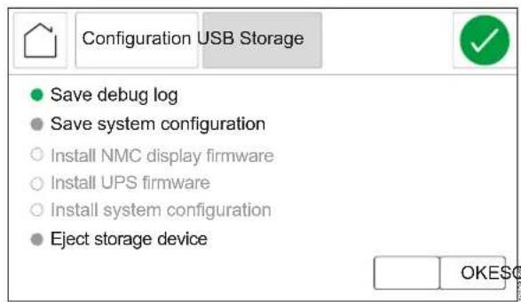
Use this feature to
- Save debug log or system configuration on a USB storage device.
• Install a signed version of NMC display firmware, UPS firmware or system configuration from a USB storage device.
This screen gets enabled only when a USB storage device is inserted to the USB port either on the rear panel (refer to "Rear Panel Features" on page 27 for location) or on the LCD display (refer to "LCD Display" on page 43 for location).
The following options are enabled by default when a USB storage device is inserted into the USB port:
- Save debug log
- Save system configuration
The following options get enabled only when the inserted USB storage device containing a signed version of the installation files is inserted into the USB port:
• Install NMC display firmware
• Install UPS firmware
• Install system configuration
To use this feature:
i. Touch the appropriate option, to enable the option.
ii. Touch the OK button.
To eject the storage device:
i. Touch the Eject storage device to enable it.
ii. Touch the OK button.
Control
UPS
Navigate through Home → Control → UPS to access the UPS Control features.
Depending the status of the UPS any of the following screens will be appear.
To instruct the UPS to execute the selected command:
i. Touch the appropriate command, to enable it.
ii. Touch the OK button to execute the selected option.
1. UPS output is on and is working in Online mode

a. Turn UPS Off
Use this command to turn off the UPS output.
b. Reboot UPS
Use this command to reboot the UPS.
c. Put UPS to Sleep
Use this command to shutdown the UPS and restart after the Sleep Time Duration configured in Timers.
Refer to "Timers setting" on page 57 for details.
NOTE: Sleep Time is available only through web GUI.
d. Put UPS in Bypass
Use this command to transfer the UPS to Command Bypass mode. Refer to "Command Bypass" on page 36 for details.
e. Clear UPS Alarms
NOTE: This command will be available only if there are any alarms in the UPS.
Use this command to clear all existing UPS alarms.
f. Skip UPS Off Delay
Enable this command to turn off the UPS output immediately. If this command is not enabled, the UPS output will be turned off after the Power Off Delay configured in Timers.
Refer to "Timers setting" on page 57 for details.
g. Skip UPS On Delay
This command will be enabled only when the UPS is in Standby mode.
Enable this command to turn on the UPS output immediately. If this command is not enabled, the UPS output will be turned on after the Power On Delay configured in Timers.
Refer to "Timers setting" on page 57 for details.
2. UPS output is off and utility power is available

a. Turn UPS On
Use this command to turn on the UPS output.
b. Clear UPS Alarm
NOTE: This command will be available only if there are any alarms in the UPS.
Use this command to clear all existing UPS alarms.
c. Skip UPS On Delay
Enable this command to turn on the UPS output immediately. If this command is not enabled, the UPS output will be turned on after the Power On Delay configured in Timers.
Refer to "Timers setting" on page 57 for details.
3. UPS output is off and utility power is not available

a. Turn UPS On without AC
Use this command to turn on the UPS output when utility power is not available.
b. Internal Power Off
Use this command to shutdown the UPS.
c. Clear UPS Alarms
NOTE: This command will be available only if there are any alarms in the UPS.
Use this command to clear all existing UPS alarms.
Display
Navigate through Home → Control → Display to access the Display Control features.

This feature is for restarting the LCD display and network Interface. Recommend to use this feature whenever the LCD display screens develops a lag or network gets disconnected or a reduction in data transfer speed is observed.
i. Touch the Restart Display / Network Interface command, to enable it.
ii. Touch the OK button to execute the command.
Login to LCD Display
1. Enable the Login feature:
NOTE: Refer to "Network Management Interface" on page 77 for details on logging in to the NMC web page.
a. Navigate to Configuration → UPS → General, in the NMC webpage.
b. Set User Mode field to Locked or Authentication Needed.
Login credentials need to be entered only once when Locked mode is chosen.
Login credentials need to be entered every time a changed setting is to be saved, when Authentication Needed mode is chosen.
NOTE: Login credentials need to be entered after the time configured in Auto Log Off elapses. Refer to "Auto Log Off NOTE: This setting will be effective only if the Login feature in the Main Menu is enabled (refer to "Login to LCD Display" on page 70 for details on enabling Login feature). Set the time for which the LCD display can remain inactive, after which the login credentials must be re-entered." on page 64 for details.
2. Login to the LCD display:


a. Touch the Home icon to enter the main menu.
b. Touch the Login button to open the Login Screen.
c. Touch the shaded area, adjacent to the User Name field, to pop up the keypad.
d. Enter the same username and password used for accessing the NMC webpage.
e. Touch the LOGIN button to login into the LCD display.
3. Logout of the LCD display

a. Touch the Home icon to enter the main menu.
b. Touch the LOGOUT button and follow on-screen instructions to logout.
Update Firmware
NOTE: The firmware can be updated only when the UPS input supply is available and the UPS output is turned OFF.
Through USB
NMC display firmware update
- Insert the USB storage device, containing the NMC display firmware update, into the USB port located on the LCD display (refer to "LCD Display" on page 43 for details).
- A pop-up screen appears acknowledging the connected USB storage device. Touch the OK button to continue.
- Select Install NMC display firmware option on the pop-up screen and touch the OK button.
- Select Yes to continue the updating process in Transferring firmware to UPS screen. If you wish to abort the updating process, select No.
- Wait for the NMC display to reboot; will take a couple of minutes to reboot.
- Status LED ( Ⓗ in "LCD Display" on page 43) will illuminate amber during the update.
- A progress bar will appear and it will take several minutes for the update to complete.
- Navigate to USB Storage to confirm that the update is completed.
- Select Eject storage device option and touch the OK button to eject the USB storage device.
UPS firmware update
- Insert the USB storage device, containing the UPS firmware update, into the USB port located on the LCD display (refer to "LCD Display" on page 43 for details).
- A pop-up screen appears acknowledging the connected USB storage device. Touch the OK button to continue.
- Select Install the UPS firmware option on the pop-up screen and touch the OK button.
- Select Yes to continue the updating process in Transferring firmware to UPS screen. If you wish to abort the updating process, select No.
- A progress bar will appear and it will take approximately 15 minutes for the update to complete.
NOTES:
- The LCD screen will return to the home screen after 30 seconds unless it is touched once before 30 seconds.
-
To see the progress of update, navigate to Home → Configuration → USB Storage.
-
Navigate to USB Storage to confirm that the updates are completed.
-
Select Eject storage device option and touch the OK button to eject the USB storage device.
Through NMC web page
- Log in to the NMC web page (refer to the NMC user documentation).
- Navigate to Configuration in the dropdown menu.
- Select Firmware update option and click on the UPLOAD button.
- Select choose file and navigate to the folder (on the local computer) containing the signed firmware package or drag and drop the signed firmware package (from the local computer) into the "Upload from Local Machine ..." box on the web page.
- Click on UPDATE UPS button to commence the update.
- When the progress bar indicates completion, the UPS will begin updating. This will take several minutes.
- Log out from the NMC web page once the UPS completes updating.
Download Log Files
Through USB
- Insert an USB storage device into the USB port located on the LCD display (refer to "LCD Display" on page 43 for details).
- A pop-up screen appears acknowledging the connected USB storage device. Touch the OK button to continue.
- Select Save debug log (refer to "USB Storage setting" on page 66 for details) and touch the OK button.
- A prompt will appear once the export of log file is completed. The log file will be a compressed TAR file.
- Select Eject storage device option and touch the OK button to eject the USB storage device.
- Extract the configuration file (config.ini), data log (data.txt) and event log (event.txt) files from the TAR file.
Through NMC web page
- Refer to "Support Screen" section in the NMC user guide for details to download the log files.
Emergency Power Off
Overview
The Emergency Power Off (EPO) option is a feature that will immediately disconnect all connected equipment from utility power. The UPS will shut down immediately and will not switch to battery power.
During an EPO event, the SYSTEM/INVERTER ENABLE switch will move to OFF position.
To power up the connected equipment again, set the SYSTEM/INVERTER ENABLE switch to ON position and power recycle the UPS, i.e., Turn off the utility power input and the BM(s) and turn them on again (the BM can be turned on and off through the BATTERY ON/OFF switch). After the UPS turns on, to continue with normal operation, prior EPO event must be acknowledged on the display screen.
Normally open contacts
-
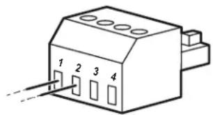
If the EPO switch or relay contacts are normally open, insert the wires from the switch or contacts at positions 1 and 2 of the EPO terminal block. Use 16-28 AWG wire.
-
Tighten the screws to secure the wires.
If the contacts are closed, the UPS will turn off and the connected equipment will not receive power.
Normally closed contacts
-
If the EPO switch or relay contacts are normally closed, insert the wires from the switch or contacts at positions 1 and 3 of the EPO terminal block. Use 16-28 AWG wire.
-
Insert a wire jumper between positions 1 and 2 of the EPO terminal block.
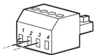
- Tighten the screws to secure the wires.
If the contacts are open, the UPS will turn off and the connected equipment will not receive power.
NOTE: Position 1 is the power source for the EPO circuit; it provides a few milliamperes of 24 V power.
If the normally closed (NC) EPO configuration is used, the EPO switch or relay should be rated for "dry" circuit applications. The switch or relay contact rating should be for low voltage and low current applications. This normally implies the contacts are gold plated.
The EPO interface is a Safety Extra Low Voltage (SELV) circuit. Connect the EPO interface only to other SELV circuits. The EPO interface monitors circuits that have no determined voltage potential. SELV circuits are controlled by a switch or relay properly isolated from utility power. To avoid damage to the UPS, do not connect the EPO interface to any circuit other than a SELV circuit.
Use one of the following cable types to connect the UPS to the EPO switch:
- CL2: Class 2 cable for general use.
- CL2P: Plenum cable for use in ducts, plenums, and other spaces used for environmental air.
- CL2R: Riser cable for use in a vertical run in a floor-to-floor shaft.
- CLEX: Limited use cable for use in dwellings and for use in raceways.
- Installation in Canada: Use only CSA certified-type ELC (Extra Low-voltage Control cable).
- Installation in countries other than Canada and USA: Use standard low voltage cable in accordance with national and local regulations.
Network Management Interface
Introduction
The UPS has a network port and a console port that can be used to access the Network Management Interface.
The Network Management Interface has the same firmware, operation modes, and interaction with other APC products such as PowerChute ® Network Shutdown.
Features
The Network Management Interface allows the UPS to function as a Web-based, IPv6 ready product.

The Network Management Interface can manage the UPS using multiple open standards such as:
| Hypertext Transfer Protocol (HTTP) Secure S | Hell (SSH) |
| Simple Network Management Protocol versions 1 and 3 (SNMPv1, SNMPv3) | Hypertext Transfer Protocol over Secure Sockets layer (HTTPS) |
| File Transfer Protocol (FTP) Secure Copy (SCP) | |
| Telnet Syslog | |
| RADIUS | |
The Network Management Interface:
- Provides UPS control and Self-test scheduling features.
- Provides data and event logs.
- Enables set-up notifications through event logging, e-mail, and SNMP traps.
- Provides support for PowerChute Network Shutdown.
- Supports using a Dynamic Host Configuration Protocol (DHCP) or BOOTstrap Protocol (BOOTP) server to provide the network (TCP/IP) values.
- Supports the use of a Remote Monitoring Service (RMS).
- Provides the ability to export a user configuration (.ini) file from a configured UPS to one or more unconfigured UPS without conversion to a binary file.
- Provides a selection of security protocols for authentication and encryption.
- Communicates with StruxureWare Central and InfraStruxure Manager.
- Supports one universal input/output port for connection to a:
– Temperature probe, AP9335T (supplied)
– Temperature/humidity sensor, AP9335TH (optional)
- Relay input/output connector that supports two input contacts and one output relay, AP9810 Dry Contact I/O Accessory (optional)
Related Documents
For related documents refer, our web site, www.apc.com.
IP Address Configuration
The default TCP/IP configuration setting, DHCP, assumes that a properly configured DHCP server is available to provide TCP/IP settings to the Network Management Interface.
If the Network Management Interface obtains an IPv4 address from a DHCP server, use the LCD display to navigate Home → About → Network, to view the address.
To setup a static IPv4 address use the LCD display to navigate
Home → Configuration → Network, to set the IP address, Subnet Mask and Gateway.
Upgrade Firmware
The firmware of the UPS, BM, and XBP can be updated using the web-interface, which is built into the UPS network management card. The encrypted image of each subsystem is combined into a single, digitally signed binary image, to provide an advance level of security and tamper proofing.
- Be sure that the Network Management Card is configured and connected to the network.
- Login to the web interface with a valid username and password.
- Read the firmware upgrade release notes and be sure that the new firmware image is compatible with your UPS model and the existing firmware version.
- Be sure that adequate battery backup is available before initiating the firmware update.
- Go to the Firmware update section in the web interface, select the valid signed binary image and initiate the update. It may take several minutes for the update(s) to be installed.
- Verify the firmware version in the About menu to be sure that the firmware update was successful.
Smart Battery Management
Definitions
- Battery Module (BM): A string of battery cells arranged to produce a battery assembly with a connector. Replacement BMs can be ordered from our web site, www.apc.com.
- External Battery Pack (XBP): An enclosure that contains BM(s) and battery communication electronics.
- User Interface (UI): An interface by which a user can interact with the system. This may include a LCD display, a network management interface or PowerChute™ Network Shutdown software.
NOTE:
- Do not use a BM that is not approved by Schneider Electric.
- The system will not detect the presence of a BM not approved by Schneider Electric and may adversely affect the operation of the system.
- Use of a BM not approved by Schneider Electric will void the manufacturer's warranty.
User interface
View Status/Error notifications: The status of connected XBP(s) can be viewed on the LCD display using the menu options.
Battery Module Status LEDs: Refer to "Status LEDs" on page 40 for details.
To clear a detected internal error in the BM:
- Disconnect the BM by disengaging the thumbscrew (located on the front panel of the BM).
- Be sure that the Battery Module Status LED is not illuminated.
- Tighten the thumbscrew to connect the BM.
If the detected internal error persists even after 3 attempts, then contact Customer Support.
System interfaces: BM status, alerts, and measurements can be viewed on the LCD display.
Maintenance
- BM maintenance: The APC BM uses Lithium-ion battery cells and does not require maintenance.
- Battery health monitoring: The battery energy output and voltage are monitored to assess the health of the installed batteries when the UPS is operating on battery. Battery health monitoring is done during a Self-test and when the UPS is operating on battery power.
End of useful life
- Near end-of-life notification: An alert message will appear on the LCD display screen when a BM is approaching the end of its useful life. For configuration details, refer to “Battery Alarm Warning” on page 58 and “Battery Alarm Sleep” on page 58. The estimated replacement date for each BM is available through the UI.
- Needs replacement notification: The replacement due date of a BM will appear on the LCD display. The BM must be replaced as soon as possible.
When a BM requires replacement, recommendation of the additional BM(s) nearing end of their useful life will also appear on the LCD display.
NOTE: Continued operation after the Needs replacement notification may cause damage to the batteries.
Recycling the BM
- Remove the BM from the UPS or XBP.
- Recycle the BM.
CAUTION: Do not disassemble the BM.
Recommended actions after installing new BM or XBP
The following actions should be performed after installing a new BM or XBP:
- When a new BM or XBP is installed, the Battery Module Status LED illuminates green in the BM(s), indicating that the BM or XBP is detected by the system and is working normally.
If Battery Module Status LED illuminates either Red or Amber in any of the BM(s), refer to "Status LEDs" on page 40 for details.
- Verify that the UPS is connected to input power and output power is turned on.
- Use the LCD display to navigate to the status menus to verify that the UPS recognizes the BM(s) or XBP.
- Be sure that the connected load to the UPS is greater than 400 watts. This information will appear on the LCD display.
- Perform a Self-test by navigating Home → Tests → UPS Self-test. During this test, the UPS will change over to On-battery mode for a short time to assess the health of the BMs and XBP, if connected.
- If at the time of XBP installation, UPS input power is not available, turn on the UPS output from battery power for 30 seconds. This will allow the UPS to detect all installed BM(s) or XBP(s). Refer to "Turn on / Turn off the UPS" on page 41 for instructions on how to turn the UPS on when input power is not available.
- Allow the BMs to charge for 24 hours to ensure full runtime capability.
Troubleshooting
Use the table below to solve minor installation and operation problems.
Refer our web site, www.apc.com for assistance with complex UPS problems.
The UPS features firmware that can be upgraded.
Visit our web site, www.apc.com/Support, or contact your local Customer Care Center for more information.
| Problem and Possible Cause Solution | |
| UPS is not turning on or there is no output | |
| The UPS is not connected to utility power. | Be sure that the hardwiring is secured both in the UPS and the utility power supply. |
| UPS output connections are not secured properly. | Be sure that the UPS output connections are secured properly. |
| SYSTEM/INVERTER ENABLE switch is set to OFF. | Turn on the SYSTEM/INVERTER ENABLE switch. |
| Thumbscrew on any of the PMs, or BMs, or IMs is not completely engaged. | Be sure that the thumbscrews on all the modules are completely engaged. |
| The LCD display screen shows very low or no utility power. | Check the utility power supply to be sure that the power quality is within acceptable limits. |
| The UPS has detected an internal error. | The LCD display screen will show a message to identify the alert and corrective action required. |
| UPS emits an alarm tone | |
| Normal UPS operation when running on battery power. | The UPS is operating on battery power.Refer to the status of the UPS displayed on the LCD display screen.Press any button to mute the audible alarm tone. |
| The UPS emits an audible alarm tone and the color of the UPS display interface changes to red or amber. | The UPS has detected an internal error.Refer to the LCD display screen for information. |
| UPS does not provide expected backup time | |
| The UPS BMs are weak due to a recent power outage or they are near the end of their service life. | Charge the BMs. Batteries require recharging after extended outages and wear out faster when put into service often or when operated at elevated temperatures. If the batteries are nearing the end of their service life, consider replacing the batteries even if the Replace Battery message is not displayed. |
| The UPS is experiencing an overload condition. | The connected equipment exceeds the specified maximum load. Visit our web site, www.apc.com for product specifications.The UPS will emit a sustained audible alarm until the overload condition is corrected.Disconnect nonessential equipment from the UPS to correct the overload condition.NOTE: If the problem still persists, disconnect the UPS from the utility power source and turn off the SYSTEM/INVERTER ENABLE switch and start up the UPS again. |
| The UPS experiences an overload condition | |
| A power module has been removed from the UPS frame. | NOTE: Removing a power module could result in overload of the remaining power modules.Replace the power module or reduce the connected load to be well within the capacity of the power modules available in the UPS frame. |
| UPS operates on battery power while connected to utility power | |
| The UPS is performing a Self-test. Wait for the UPS to complete the Self-test. | |
| The utility power circuit breaker has tripped. | Be sure that the utility power circuit breaker is rated for the connected load of the UPS. |
| There is very high, very low, or distorted input line voltage. | Navigate to the LCD display screen that shows input voltage. Be sure that the input voltage is within the specified operating limits.If no input voltage is indicated on the LCD display screen, contact Customer Support. |
| The LCD display screen shows the message Waiting for Minimum Runtime. | The UPS output does not turn on when the battery runtime is lower than the configured minimum return runtime.Wait till the battery gets charged orChange the minimum return runtime setting through Home → Config → UPS → Timers menu. |
| LCD display screen shows Overload and the UPS emits an audible alarm tone | |
| The UPS is experiencing an overload condition. | Rating of the connected equipment exceeds the capacity of the UPS.The UPS will emit an audible alarm tone until the overload condition is corrected.Disconnect nonessential equipment from the UPS to correct the overload condition.NOTE: If the problem still persists, disconnect the UPS from the utility power, turn off the SYSTEM/INVERTER ENABLE switch, and start up the UPS again. |
| LCD display screen shows UPS is operating in Bypass mode | |
| The UPS has gone into temporary bypass. | Check for the event, on the LCD display, which caused the UPS go into temporary bypass and take appropriate corrective action.If the UPS goes into temporary bypass whilst operating in green mode, be sure that the connected load does not exceed 105% of the UPS capacity. |
| The UPS received a command to operate in bypass mode. | No action required as the UPS has been commanded to operate in bypass mode by the user. |
| The MANUAL BYPASS switch is set to ON. | Be sure that the service personnel set the MANUAL BYPASS switch to OFF, after servicing the UPS. |
| The UPS has detected an internal error and automatically switched to event bypass mode. | The LCD display screen will show a message to identify the alert and corrective action required. |
| LCD display illuminates amber or red and displays an alert message and UPS emits an audible alarm | |
| The UPS has detected an alarm condition. | Follow the instructions on the LCD display screen.Touch any button to mute all audible alarms. |
| The LCD display screen shows the message Disconnected Battery. | Be sure that the BMs are completely inserted, the thumbscrew is completely engaged and the BATTERY ON/OFF switch is turned on. |
| Replace Battery alert is displayed | |
| The BM has a weak charge. Allow the | BM to recharge for at least 4 hours.Then, perform a Self-test. If the problem persists after recharging, replace the BM. |
| The replacement BM is not properly connected. | Be sure that the BMs are completely inserted, the thumbscrew is completely engaged and the BATTERY ON/OFF switch is set to ON. |
Transport
Service
- Shut down and disconnect all connected equipment.
- Disconnect the unit from the utility power.
-
Disconnect all the BMs and XBPs (if applicable).
-
Follow the shipping instructions outlined in the Service section of this manual.
If the unit requires service, do not return it to the dealer. Follow these steps:
- Review the "Troubleshooting" on page 81 of the manual to eliminate common problems.
- If the problem persists, contact Customer Support through our web site, www.apc.com.
a. Note the model number and serial number and the date of purchase. The model and serial numbers are located on the top left corner of the rear panel of the unit and are also available through the LCD display.
b. Call Customer Support. A technician will attempt to solve the problem over the phone. If this is not possible, the technician will issue a Return Material Authorization Number (RMA#).
c. If the unit is under warranty, the repairs are free.
d. Service procedures and returns may vary internationally. For country specific instructions, refer to the APC web site, www.apc.com.
-
Shipment of Lithium-ion Battery is highly regulated and the regulation is evolving. Pack the BM and UPS separately.
-
Always contact Customer Support to get the latest guidance on the shipment of Lithium-ion battery and UPS.
-
Pack the unit properly to avoid damage in transit. Do not use foam beads for packaging. Damage sustained in transit is not covered under the warranty.
-
Write the RMA# provided by Customer Support on the outside of the package.
-
Return the unit by insured, prepaid carrier to the address provided by Customer Support.
Limited Factory Warranty
Schneider Electric IT Corporation (SEIT), warrants its products to be free from defects in materials and workmanship for a period of five (5) years from the date of purchase. The SEIT obligation under this warranty is limited to repairing or replacing, at its own sole option, any such defective products. Repair or replacement of a defective product or part thereof does not extend the original warranty period.
This warranty applies only to the original purchaser who must have properly registered the product within 10 days of purchase. Products may be registered online at warranty.apc.com.
SEIT shall not be liable under the warranty if its testing and examination disclose that the alleged defect in the product does not exist or was caused by end user or any third person misuse, negligence, improper installation, testing, operation or use of the product contrary to SEIT recommendations of specifications. Further, SEIT shall not be liable for defects resulting from: 1) unauthorized attempts to repair or modify the product, 2) incorrect or inadequate electrical voltage or connection, 3) inappropriate on site operation conditions, 4) Acts of God, 5) exposure to the elements, or 6) theft. In no event shall SEIT have any liability under this warranty for any product where the serial number has been altered, defaced, or removed.
EXCEPT AS SET FORTH ABOVE, THERE ARE NO WARRANTIES, EXPRESS OR IMPLIED, BY OPERATION OF LAW OR OTHERWISE, APPLICABLE TO PRODUCTS SOLD, SERVICED OR FURNISHED UNDER THIS AGREEMENT OR IN CONNECTION HERewith.
SEIT DISCLAIMS ALL IMPLIED WARRANTIES OF MERCHANTABILITY, SATISFACTION AND FITNESS FOR A PARTICULAR PURPOSE.
SEIT EXPRESS WARRANTIES WILL NOT BE ENLARGED, DIMINISHED, OR AFFECTED BY AND NO OBLIGATION OR LIABILITY WILL ARISE OUT OF, SEIT RENDERING OF TECHNICAL OR OTHER ADVICE OR SERVICE IN CONNECTION WITH THE PRODUCTS.
THE FOREGOING WARRANTIES AND REMEDIES ARE EXCLUSIVE AND IN LIEU OF ALL OTHER WARRANTIES AND REMEDIES. THE WARRANTIES SET FORTH ABOVE CONSTITUTE SEIT'S SOLE LIABILITY AND PURCHASER EXCLUSIVE REMEDY FOR ANY BREACH OF SUCH WARRANTIES. SEIT WARRANTIES EXTEND ONLY TO ORIGINAL PURCHASER AND ARE NOT EXTENDED TO ANY THIRD PARTIES.
IN NO EVENT SHALL SEIT, ITS OFFICERS, DIRECTORS, AFFILIATES OR EMPLOYEES BE LIABLE FOR ANY FORM OF INDIRECT, SPECIAL, CONSEQUENTIAL OR PUNITIVE DAMAGES, ARISING OUT OF THE USE, SERVICE OR INSTALLATION OF THE PRODUCTS, WHETHER SUCH DAMAGES ARISE IN CONTRACT OR TORT, IRRESPECTIVE OF FAULT, NEGLIGENCE OR STRICT LIABILITY OR WHETHER SEIT HAS BEEN ADVISED IN ADVANCE OF THE POSSIBILITY OF SUCH DAMAGES. SPECIFICALLY, SEIT IS NOT LIABLE FOR ANY COSTS, SUCH AS LOST PROFITS OR REVENUE, WHETHER DIRECT OR INDIRECT, LOSS OF EQUIPMENT, LOSS OF USE OF EQUIPMENT, LOSS OF SOFTWARE, LOSS OF DATA, COSTS OF SUBSTITUANTS, CLAIMS BY THIRD PARTIES, OR OTHERWISE.
NOTHING IN THIS LIMITED WARRANTY SHALL SEEK TO EXCLUDE OR LIMIT SEIT LIABILITY FOR DEATH OR PERSONAL INJURY RESULTING FROM ITS NEGLIGENCE OR ITS FRAUDULENT MISREPRESENTATION OF TO THE EXTENT THAT IT CANNOT BE EXCLUDED OR LIMITED BY APPLICABLE LAW.
To obtain service under warranty you must obtain a Returned Material Authorization (RMA) number from customer support. Customers with warranty claims issues may access the SEIT worldwide customer support network through the APC web site: www.apc.com. Select your country from the country selection drop down menu. Open the Support tab at the top of the web page to obtain information for customer support in your region. Products must be returned with transportation charges prepaid and must be accompanied by a brief description of the problem encountered and proof of date and place of purchase.
APC Worldwide Customer Support
Customer support for this or any other APC product is available at no charge in any of the following ways:
- Visit our web site to access documents in the APC Knowledge Base and to submit customer support requests.
- www.apc.com (Corporate Headquarters)
Connect to a localized APC web site for specific countries, each of which provides customer support information.
- www.apc.com/support/
Global support for searching APC Knowledge Base and using e-support.
- Contact the APC Customer Support Center by telephone or e-mail.
- Local, country specific centers: go to www.apc.com/support/contact for contact information.
- For information on how to obtain local customer support, contact our representative or the distributor from whom you purchased your APC product.

Select models are ENERGY STAR® qualified.
For more information on your specific model refer to our web site, www.apc.com.
Schneider Electric
As standards, specifications, and designs change from time to time, please ask for confirmation of the information given in this publication.
© 2023 Schneider Electric. All Rights Reserved.
EN 990-6492A
- SMART-UPS™ MODULAR ULTRA UNINTERRUPTIBLE POWER SUPPLY
- LEGAL INFORMATION
- CONTENTS
- IMPORTANT SAFETY INSTRUCTIONS
- DANGER
- WARNING
- CAUTION
- NOTICE
- PRODUCT HANDLING GUIDELINES
- FCC CLASS A RADIO FREQUENCY WARNING
- PRODUCT OVERVIEW
- SPECIFICATIONS
- ELECTRICAL
- RISK OF FIRE
- WIRING (HARDWIRE)
- PACKAGE CONTENTS
- INSTALLATION
- UNPACKING
- RISK OF DROPPED OR FALLING EQUIPMENT
- UPS FRAME
- BATTERY FRAME
- INSTALL FRAMES IN A 4 POST RACK
- MODELS WITH UPS FRAME ONLY
- MODELS WITH BOTH UPS AND BATTERY FRAMES
- INSTALL FRAMES IN A 2 POST RACK
- INSTALL POWER MODULE(S) AND BATTERY MODULE(S)
- FAILURE TO FOLLOW THESE INSTRUCTIONS COULD RESULT IN EQUIPMENT DAMAGE AND MINOR OR MODERATE INJURY
- REMOVE BLANKING PANELS
- REMOVE POWER MODULE AND BATTERY MODULE
- REAR PANEL FEATURES
- FRONT PANEL FEATURES
- UPS
- HARDWIRING
- RISK OF ELECTRIC SHOCK
- TERMINAL CONFIGURATION
- CONNECT BATTERY FRAME
- CONNECT A SINGLE BATTERY FRAME TO UPS
- CONNECT MULTIPLE BATTERY FRAMES TO UPS
- BATTERY CABLE EXTENSION
- OPERATION
- MODES
- ON-LINE
- ON-BATTERY
- GREEN
- BYPASS MODE
- TEMPORARY BYPASS
- COMMAND BYPASS
- MANUAL BYPASS
- EVENT BYPASS
- STANDBY MODE WITH AC PRESENT
- STANDBY MODE WITH AC NOT PRESENT
- SYSTEM ALARM
- SET THE UPS TO MANUAL BYPASS MODE
- ONE LINE DIAGRAM STATUS INDICATORS
- STATUS LEDS
- START UP
- TURN ON / TURN OFF THE UPS
- TUM ON
- TURN ON WITHOUT UTILITY POWER
- TUM OFF
- LCD DISPLAY
- OPERATING THE LCD DISPLAY
- TYPICAL ALERT/NOTIFICATION/ALARM SCREENS
- ICONS
- OPERATION MODE ICONS
- NOTIFICATION ICONS
- BATTERY STATUS ICONS
- MAIN MENU SCREEN
- UPS MENU OVERVIEW
- MAIN MENU
- STATUS
- SYSTEM
- INPUT
- OUTPUT
- OVERVIEW
- BATTERY MODULES
- ACTIVE ALARMS
- DISPLAY
- CONFIGURATION
- STARTUP CONFIGURATION
- SET THE LANGUAGE OF LCD DISPLAY
- OPTIONS
- SET OUTPUT VOLTAGE
- SET ALARM IF REDUNDANCY UNDER
- SET TIME ZONE, CURRENT DATE, AND TIME
- SET INSTALLATION DATE
- GENERAL SETTINGS
- OUTPUT SETTINGS
- RATED VOLTAGE
- FREQUENCY RANGE
- FREQUENCY SLEW RATE
- GREEN MODE
- OUTPUT LOWER ACCEPTABLE VOLTAGE
- OUTPUT UPPER ACCEPTABLE VOLTAGE
- BYPASS SETTING
- BYPASS ALLOWED
- DEFAULT VALUE: PHASE LOCK NOT REQUIRED
- DEFAULT VALUE
- TIMERS SETTING
- ALARMS SETTING
- LOAD SHEDDING SETTING
- TIME ON BATTERY
- RUNTIME REMAINING
- USE OFF DELAY
- MANUAL RESTART REQUIRED
- DISPLAY SETTING
- LANGUAGE
- ALARM VOLUME
- DEFAULT: HIGH
- BUTTON VOLUME
- BRIGHTNESS
- ENABLE BACKLIGHT TIMEOUT
- BACKLIGHT TIMEOUT
- INTENSITY
- AUTO LOG OFF
- NETWORK SETTINGS
- ADDRESS MODE
- DATE AND TIME SETTING
- 11.USB STORAGE SETTING
- CONTROL
- UPS OUTPUT IS ON AND IS WORKING IN ONLINE MODE
- SKIP UPS ON DELAY
- UPS OUTPUT IS OFF AND UTILITY POWER IS AVAILABLE
- UPS OUTPUT IS OFF AND UTILITY POWER IS NOT AVAILABLE
- LOGIN TO LCD DISPLAY
- ENABLE THE LOGIN FEATURE
- LOGIN TO THE LCD DISPLAY
- LOGOUT OF THE LCD DISPLAY
- UPDATE FIRMWARE
- THROUGH USB
- NMC DISPLAY FIRMWARE UPDATE
- UPS FIRMWARE UPDATE
- NOTES
- THROUGH NMC WEB PAGE
- DOWNLOAD LOG FILES
- EMERGENCY POWER OFF
- NORMALLY OPEN CONTACTS
- NORMALLY CLOSED CONTACTS
- NETWORK MANAGEMENT INTERFACE
- INTRODUCTION
- FEATURES
- RELATED DOCUMENTS
- IP ADDRESS CONFIGURATION
- UPGRADE FIRMWARE
- SMART BATTERY MANAGEMENT
- DEFINITIONS
- NOTE
- USER INTERFACE
- MAINTENANCE
- END OF USEFUL LIFE
- RECYCLING THE BM
- RECOMMENDED ACTIONS AFTER INSTALLING NEW BM OR XBP
- TROUBLESHOOTING
- TRANSPORT
- SERVICE
- LIMITED FACTORY WARRANTY
- APC WORLDWIDE CUSTOMER SUPPORT
Brand : APC
Model : Smart-UPS Modular Ultra SRYL5K15RMXLT
Category : UPS