
Smart-UPS SRTL002 - UPS APC - Free user manual and instructions
Find the device manual for free Smart-UPS SRTL002 APC in PDF.

| Product Type | UPS (Uninterruptible Power Supply) |
| Brand | APC |
| Model | Smart-UPS SRTL002 |
| Manual Language | English |
| Total Pages | 4 |
| File Format | |
| Release Date | 2021 |
| Safety | Includes Important Safety Instructions with DANGER, WARNING, CAUTION, and NOTICE labels |
| PDU Type | Hardwiring PDU (SRTL002) |
| Receptacles | None (hardwired connection) |
| Input/Output Connection | Hardwired via terminals (Line, Neutral, Ground) |
| Installation | Must be performed by a qualified electrician |
| Compliance | Adhere to all local and national electrical codes |
| Package Contents | PDU unit, ground wire, screws, clips, and instruction manual |
| Tools Required | Torx T20 driver bit, strain relief (M4844 by Heyco or equivalent) |
| Warranty & Support | Available at www.apc.com |
| Compatible Models | SRTL002, SRTL003, SRTL004, SRTL005 (PDU replacement procedure) |
| Special Notes | Hardwiring applicable only for SRTL002; turn off UPS output and input before servicing |
Frequently Asked Questions - Smart-UPS SRTL002 APC
User questions about Smart-UPS SRTL002 APC
0 question about this device. Answer the ones you know or ask your own.
Ask a new question about this device
Download the instructions for your UPS in PDF format for free! Find your manual Smart-UPS SRTL002 - APC and take your electronic device back in hand. On this page are published all the documents necessary for the use of your device. Smart-UPS SRTL002 by APC.
USER MANUAL Smart-UPS SRTL002 APC
Installation Guide APC ^TM Smart-UPS ^TM Ultra Power Distribution Unit (PDU) SRTL002/SRTL003/SRTL004/SRTL005
Important Safety Instructions
SAVE THESE INSTRUCTIONS - This manual contains important instructions that should be followed during installation and maintenance of the Smart-UPS and batteries.

Read the user documentation to become familiar with the equipment before trying to install or operate it.
The following special messages may appear throughout this bulletin or on the equipment to warn of potential hazards or to call attention to information that clarifies or simplifies a procedure.
The addition of this symbol either to a "Danger" or "Warning" safety label indicates that an electrical hazard exists which will result in personal injury if the instructions are not followed.

This is the safety alert symbol. It is used to alert you to potential personal injury hazards. Obey all safety messages that follow this symbol to avoid possible injury or death.

DANGER
DANGER indicates a hazardous situation which, if not avoided, will result in death or serious injury.

WARNING
WARNING indicates a hazardous situation which, if not avoided, could result in death or serious injury.

CAUTION
CAUTION indicates a hazardous situation which, if not avoided, could result in minor or moderate injury.
NOTICE
NOTICE is used to address practices not related to physical injury.
Package Contents
Inspect the contents upon receipt. Notify the carrier and dealer if there is damage.
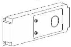
Hardwiring PDU (SRTL002)
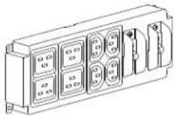
PDU with 2x L6-30 and 2x L6-20 receptacles (SRTL005)
natural_image
Technical line drawing of a rectangular electronic component with mounting holes and a central oval (no text or symbols)IEC PDU (SRTL003)
natural_image
Technical line drawing of a rectangular electronic device with multiple ports and connectors (no text or symbols)
natural_image
Technical line drawing of a mechanical or electrical component with two cylindrical tanks and three circular ports (no text or symbols)PDU with 4x L6-20 receptacles (SRTL004)

natural_image
Technical line drawing of a rectangular electrical outlet with four circular outlets and mounting holes (no text or symbols)PDU Replacement

CAUTION
RISK OF DAMAGE TO EQUIPMENT OR PERSONNEL
- PDU must replaced by a qualified electrician or a service personnel.
- Adhere to all local and national electrical codes.
Failure to follow these instructions could result in equipment damage and minor or moderate injury.
The PDU in the following illustration is only for representation. The procedure is applicable for all the PDUs, SRTL002, SRTL003, SRTL004, and SRTL005.
Removal of the existing PDU
| 1 | Turn off the UPS Output (refer to the UPS Operation Manual for details) by selecting the Turn Off Immediately option. | ||
| 2 | Turn off the input power to the UPS at the wall socket. | ||
| 3 | Loosen the thumbscrew and turn off the BATTERY ON/OFF switch, on the internal battery module in the UPS. | ||
| 4 | Disconnect XLBPs connected to the UPS, if any. | ||
| 5 | Unplug all the connected equipment from the output sockets of the UPS. | ||
| 6 | Locate the screws securing the standard PDU to the UPS and unfasten them using a Torx® T20 driver bit. | 7 | Slide the PDU to the left to align the locking pin with the keyhole. |
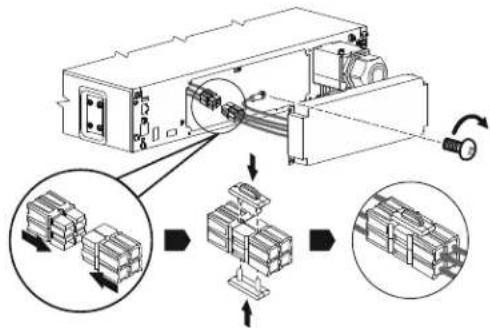
8
a. Pull out the PDU.
b. Remove the clips (on the top and the bottom) securing the connectors and pull the connectors apart..

flowchart
graph TD
    A["Material Input"] --> B["Process Unit"]
    B --> C{Processing Step}
    C -->|Downward Arrow| D["Stacked Units"]
    C -->|Upward Arrow| E["Stacked Units"]
    D --> F["Output"]
    E --> F
9
Locate the screw securing the ground wire to the ground terminal and unfasten it.

natural_image
Technical line drawing of an electronic device with internal components and a rotating indicator (no text or symbols)Installation of the replacement PDU
1
a. Connect the ground wire of the replacement PDU to the ground terminal. b. Insert the PDU connector into the UPS connector and install the top and bottom clips to secure the connectors.
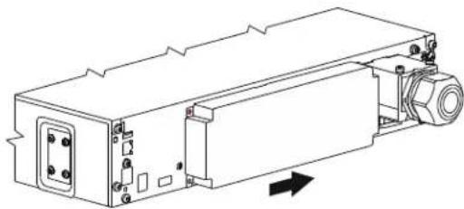
2
Align the locking pin on the UPS and the key hole on the PDU and insert the PDU.
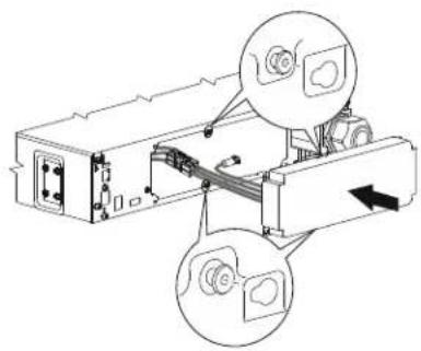
natural_image
Technical line drawing of a mechanical assembly with two circular insets showing component views (no text or labels)3
Slide the PDU to the right to lock the PDU in position.
natural_image
Technical line drawing of a mechanical device with mounting holes and internal components (no text or symbols)4
Secure the PDU to the UPS by fastening the screw using a Torx ^® T20 driver bit.
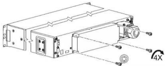
natural_image
Technical line drawing of an electronic device with ports and a 4X rotational indicator (no text or symbols)5
NOTE: This step is applicable only for SRTL002. Hardwire the PDU. Refer to "Hardwiring" on page 4 for details.
6
Re-connect all the connected equipment to the output sockets of the UPS.
7
Re-connect the XLBPs to the UPS, if any.
8
Turn on the BATTERY ON/OFF switch in the internal battery module and tighten the thumbscrew on the internal battery module completely.
9
Turn on the input power to the UPS at the wall socket.
10
Turn on the UPS output (refer to the UPS Operation Manual for details).
Hardwiring
NOTE: Applicable only for SRTL002.
| 1 | Remove the knock-out.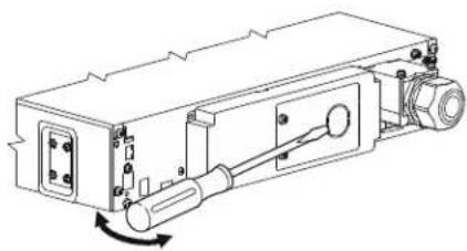 | 2 | Locate the screws securing the PDU cover and unfasten the screws using a Torx® T20 driver bit. |
| 3 | Install the strain-relief (not supplied) on the PDU cover. NOTE:The recommended strain relief is M4844 manufactured by Heyco or equivalent. NOTE:The recommended strain relief is M4844 manufactured by Heyco or equivalent. | 4 | Insert the wire through the strain-relief and secure the wires to the terminals. NOTE: Be sure to connect the Line wire to the top terminal; the Neutral wire to the middle terminal; and the ground wire to the bottom terminal. NOTE: Be sure to connect the Line wire to the top terminal; the Neutral wire to the middle terminal; and the ground wire to the bottom terminal. |
| 5 | Secure the PDU cover by fastening the screws using a Torx® T20 driver bit. | ||
Customer support and warranty information are available on our web site, www.apc.com.
© 2021 Schneider Electric. All rights reserved. Schneider Electric, Life is On | Schneider Electric, the Schneider Electric logo, APC, the APC logo and Smart-UPS are trademarks of Schneider Electric SE, its subsidiaries or affiliated companies. All other brands may be trademarks of their respective owners.
- Installation Guide APC TM Smart-UPS TM Ultra Power Distribution Unit (PDU) SRTL002/SRTL003/SRTL004/SRTL005
- Important Safety Instructions
- DANGER
- WARNING
- CAUTION
- NOTICE
- Package Contents
- PDU Replacement
- RISK OF DAMAGE TO EQUIPMENT OR PERSONNEL
- Removal of the existing PDU
- Installation of the replacement PDU
- Hardwiring
Brand : APC
Model : Smart-UPS SRTL002
Category : UPS