The Rock TR-100 - Tripod Carson - Free user manual and instructions
Find the device manual for free The Rock TR-100 Carson in PDF.

| Product Type | Camera Tripod |
| Brand | Carson |
| Model | The Rock TR-100 |
| Maximum Height | 150 cm (59 in) |
| Minimum Height | 45 cm (17.7 in) |
| Folded Length | 55 cm (21.7 in) |
| Weight Capacity | 5 kg (11 lb) |
| Weight | 1.2 kg (2.65 lb) |
| Leg Sections | 4 |
| Leg Lock Type | Flip locks |
| Material | Aluminum alloy |
| Head Type | Ball head with pan handle |
| Quick Release Plate | Yes, Arca-Swiss compatible |
| Center Column | Yes, geared |
| Spike Feet | Yes, retractable |
| Leveling Bubble | Yes, built-in |
| Power Source | None (manual) |
| Primary Functions | Stable support for cameras, telescopes; low angle shooting |
| Care and Cleaning | Wipe with dry cloth; avoid water and solvents |
| Safety | Do not exceed weight capacity; secure locks properly |
| Spare Parts / Repairability | Replacement plates and screws available; contact Carson |
| General Information | Designed for durability and portability |
Frequently Asked Questions - The Rock TR-100 Carson
User questions about The Rock TR-100 Carson
0 question about this device. Answer the ones you know or ask your own.
Ask a new question about this device
Download the instructions for your Tripod in PDF format for free! Find your manual The Rock TR-100 - Carson and take your electronic device back in hand. On this page are published all the documents necessary for the use of your device. The Rock TR-100 by Carson.
USER MANUAL The Rock TR-100 Carson
with 3-Way Fluid Panhead
Congratulations on selecting your new Tripod! In order to achieve optimum performance, please follow instructions for proper use and care.
PRODUCT SPECIFICATION:
| Head Type: | 3-Way Fluid Panhead |
| Leg Sections: | 3 |
| Maximum Height: | 20.8" |
| Maximum Tube Diameter: | 20.5mm |
| Maximum Load: | 5.5 lbs. |
| Features: | Bubble Level, Quick Release Plate, Non-Slip Rubber Feet, and Carrying Case |

natural_image
Black tripod-mounted camera with adjustable arm and tripod base (no visible text or symbols)TR-100
TR-100 PANHEAD DIAGRAM:

text_image
MOUNTING SCREW QUICK RELEASE PLATE HORIZONTAL TILT LOCKING KNOB PLATE LOCKING LEVER BUBBLE LEVEL PAN LOCKING KNOB TILT/PAN HANDLEIMPORTANT:
- Do not exceed maximum load capacity of the tripod.
- Do not mount optic to tripod until all legs are securely locked, level and stabilized.
• Make sure all panhead locks are tightened securely before mounting any optic. - Do not overtighten locks as this may damage the locking mechanisms.
- Make sure optic is securely fastened to quick release plate before mounting to tripod.
- Do not carry the tripod by the panhead.
- Remove optic before adjusting or transporting your tripod.
• Always store tripod in carrying case when not in use.
Customer Service:
If you experience any difficulties please contact us and we will be happy to help you.

info@carson.com

☑ uksupport@carson.com eusupport@carson.com

For warrant information, visit www carson.com/warrant
www.carson.com
Carson Optical 2070 5th Avenue, Ronkonkoma, NY 11779 | Tel: 631-963-5000
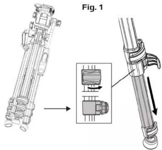
SETTING UP TRIPOD:
- Flip open leg locks and extend legs to desired height. Close leg locks to lock in place (Fig. 1).
text_image
Fig. 1- To make sure tripod is level, the bubble level should appear centered inside red circle. Adjust leg height as needed to level tripod (Fig. 2).

natural_image
Technical line drawing of a mechanical assembly with no visible text or symbols
text_image
Bubble LevelATTACHING CAMERA OR SPOTTING SCOPE:
- Pull back plate locking lever to remove quick release plate (Fig. 3).
Fig. 3

natural_image
Mechanical assembly diagram showing a valve mechanism with no visible text or symbols- Insert mounting screw into thread on optic and turn wingnut (located on underside of quick release plate) clockwise until tight. This will secure optic to plate (Fig. 4).
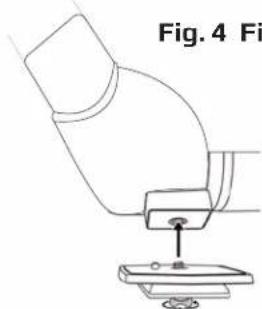
natural_image
Diagram of a microscope with a base and lens, labeled Fig. 4 (no text or symbols on the diagram itself)- Reattach quick release plate to tripod head. Press down plate and lever will shift into place and lock (Fig. 5).

natural_image
Mechanical assembly diagram showing a robotic arm interacting with a mechanical component (no text or symbols visible)ATTACHING BINOCULARS:
PLEASE NOTE: To attach your full sized binoculars to a tripod, you will need a tripod binocular adapter (not included).
- Pull back plate locking lever to remove quick release plate (Fig. 6).
- Insert mounting screw into thread on adapter and turn wingnut (located on underside of quick release plate) clockwise until tight. This will secure adapter to plate (Fig. 7).
- Reattach quick release plate to tripod head. Press down plate and lever will shift into place and lock (Fig. 8).
- Attach binocular to adapter.
Fig. 6

natural_image
Mechanical assembly diagram showing a motor or pump component with rotating shaft and housing (no text or labels)Fig. 7

natural_image
Diagram showing a mechanical component before and after assembly, with no visible text or symbolsFig. 8

natural_image
Mechanical assembly diagram showing a valve mechanism with directional arrows (no text or labels)USING TRIPOD:
- To adjust center column height, twist locking ring counterclockwise to unlock. Raise center column as needed. Tighten locking ring to secure (Fig. 9).

text_image
mm ring unlock. as ring ring Center Column Locking Ring Fig. 9- To tilt panhead up or down, twist tilt/pan handle counterclockwise to loosen. Raise or lower tilt/pan handle to desired angle. Tighten handle to lock in place (Fig. 10).
Note: To keep level, raise or lower Tilt/Pan Handle until the bubble inside the bubble level is in middle of tube.

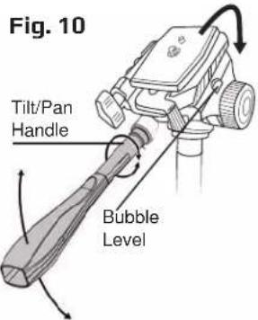
text_image
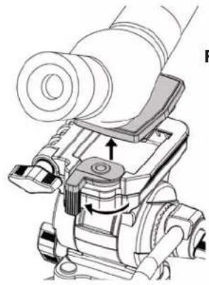
Fig. 10 Tilt/Pan Handle Bubble Level- To adjust pan angle, loosen pan locking knob by turning counterclockwise. Turn tilt/pan handle right or left as desired. Tighten knob to lock in place (Fig. 11).
Fig. 11

text_image
loosen turning rn tilt/pan s desired. in place Pan Locking Knob- To switch between landscape and portrait mode, loosen horizontal tilt locking knob by turning counterclockwise. Tilt optic to desired angle. Tighten knob to lock in place (Fig. 12).

text_image
Fig. 12REMOVING OPTIC & STORING TRIPOD:
- While holding optic securely, pull out plate locking lever and lift optic upward to remove from tripod. Unscrew quick release plate from optic and replace plate on tripod (Fig. 13).
natural_image
Technical line drawing of a mechanical device with no visible text or symbolsFig. 13
- To put tripod away, loosen tripod center column collar. Fold legs inward and unlock leg locks to retract. Tilt head back so handle is parallel to legs. Secure all locks and place in carrying bag (Fig. 14).
