SB-WM-ART2-L-BL - Support pour écran plat SunBriteTV - Free user manual and instructions
Find the device manual for free SB-WM-ART2-L-BL SunBriteTV in PDF.

User questions about SB-WM-ART2-L-BL SunBriteTV
0 question about this device. Answer the ones you know or ask your own.
Ask a new question about this device
Download the instructions for your Support pour écran plat in PDF format for free! Find your manual SB-WM-ART2-L-BL - SunBriteTV and take your electronic device back in hand. On this page are published all the documents necessary for the use of your device. SB-WM-ART2-L-BL by SunBriteTV.
USER MANUAL SB-WM-ART2-L-BL SunBriteTV
True Outdoor Television
SB-WM-ART2-L-BL
SB-WM-ART2-XL-BL
Weatherproof Universal Dual-Arm Articulating Mount for Large TVs
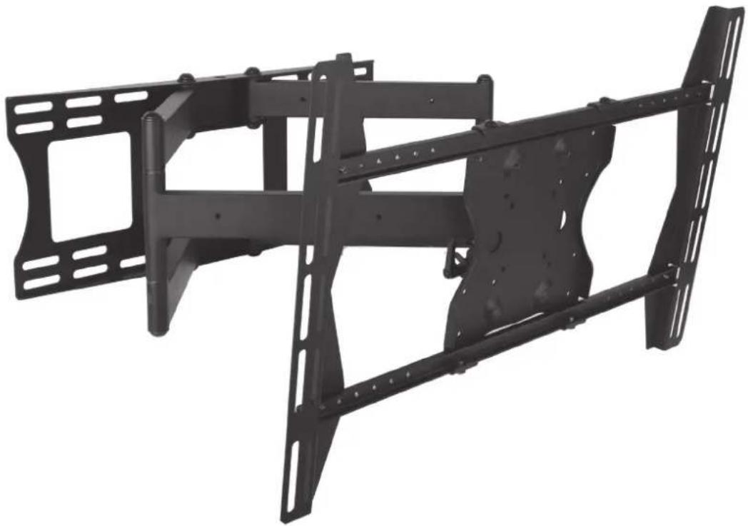
natural_image
Black metal frame structure with mounting holes and structural beams (no text or symbols visible)INSTALLATION MANUAL
Ensure these instructions are thoroughly understood before attempting installation. If unsure of any part of the installation process, contact a professional installer for assistance.
The wall or mounting surface must be capable of supporting the combined weight of the mount and the TV; otherwise the structure must be reinforced. Installer is responsible for verifying the wall/mounting surface and the anchors used can support the total load of the installation.
Safety gear and proper tools must be used. Failure to do so can result in property damage and/or serious injury.
A minimum of two people is required for this installation and it is highly recommended that this product be installed by qualified professionals.
Follow all instructions and recommendations regarding suitable locations for TV installation. Consult the TV equipment's documentation for information relative to its requirements.
NOTE: This mount supports TV mounting from VESA 200x100, 200x200, up to 600x400.
SPECIFICATIONS BOX CONTENTS TOOLS REQUIRED
• Maximum Load: 150 lbs (68.04 kg)
• Wall Arm Assembly (1) • Power Drill
• Maximum Extension: 30-5/8"
- Adapter Bracket (2) • 1/4" & 5/16" Drill Bits
- Wire Management
- Adapter Plate (1) • Level
- Pan/Swivel Range: 180^
• SunBrite Adapter Bars (4) • 1/2" (13mm) Wrench
- Tilt Range: -5^ / + 15^
• Cable Covers (6) • Hammer
- Weather Resistant Coating
- Hardware Kit (1) • Stud Finder
• Stainless Steel Mounting Hardware
- Template (1) • Phillips Screw Driver
HARDWARE
| IMAGE DESCRIPTION ITEM QUANTITY | ||||||
| BAG 1 | ||||||
 | Phillips Head Bolt | (A) M4x10(E) M5x10(I) M6x10(M) M8x10 | (B) M4x20(F) M5x20(J) M6x20(N) M8x20 | (C) M4x30(G) M5x30(K) M6x30(O) M8x30 | (D) M4x40(H) M5x40(L) M6x40(P) M8x40 | 4 of each size |
 | Flat Washer | (Q) M5(R) M8 | 168 | |||
 | Nylon Spacer | (S) M4/M5(T) M6/M8 | 88 | |||
 | Square Washer | (U) 36.2x2.5mm | 4 | |||
 | Recessed Hole Spacer | (V) Recessed Hole Spacer | 4 | |||
 | Spacer | (W) Spacer | 4 | |||
| BAG 2 | ||||||
 | Lag Bolt | (X) M8x65 Bolt | 6 | |||
 | Anchor | (Y) Concrete Anchor | 6 | |||
 | Lag Bolt Washer | (Z) Flat Washer | 6 | |||
 | Phillips Head Flange Bolt | (AA) M6x12 | 4 | |||
 | Button Head Flange Bolt | (BB) M8x12 | 4 | |||
 | Hex Key | — | 1 | |||
 | Security bit | — | 4 | |||
INSTALLATION
Layout and Drilling
-
Determine general location of the TV.
-
Use a stud finder to find the nearest wall studs if applicable and mark their location.
-
Tape template flat and level to wall surface, aligning the template's slots with the stud markings on the wall.
NOTE: Use of a bead level is recommended.
NOTE: Template corners fold up to catch debris.
- Use a pen or pointed object to mark bore locations.
ATTENTION: Before drilling, verify there is a minimum of 1-3/8" of concrete thickness to be used for the concrete anchors. Ensure to mount in a solid part of the block, generally 1" minimum from the side of the block. Cinder block must meet ASTM C-90 specifications.
ATTENTION: Concrete must be 2000 psi density minimum. Lighter density concrete may not hold concrete anchor.
ATTENTION: A standard electric drill on slow setting should be used to drill the holes instead of a hammer drill to avoid breaking out the back of the hole when entering a void or cavity.
- Drill holes (Figure 1):
- Use 1/4" bit for drilling into wooden studs (x4).
- Use 5/16" bit for drilling into concrete wall (x6).
NOTE: Two additional holes and provided anchors are needed for concrete installs.
ATTENTION: Be sure to drill holes centered within studs. Do not drill into mortar joints.
Wall Mounting of Arm Assembly
-
Hammer concrete anchors (Y) into wall as applicable (Figure 1).
-
Apply washers (Z) to lag bolts (X).
-
Hold Arm Assembly in place while applying lag bolts (X) with washers (Z).
NOTE: A properly mounted Arm Assembly will be oriented so that its Keyed Notches side of the Arm Assembly Head Mount is upward.
- Tighten bolts snugly without overtightening.
CAUTION: Overtightening can damage the bolts and reduce their holding strength. Refer to the mounting template for specifics.
Figure 1

text_image
5/16" Holes for Concrete 1/4" Holes for Studs Arm Assembly Concrete Anchors (for concrete only) Keyed Notches Washers Head Mount Lag Bolts (X)Assemble TV Bracket
Lay the TV flat on a soft, flat surface and locate the four VESA mounting bracket holes, then determine the VESA pattern and prepare the TV bracket and adapters accordingly.
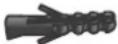
Medium Displays (Up to VESA 400X400)
-
Assemble the four SunBrite adapter arms on the TV adapter plate using 8x bolts (AA). (Fig.2A)
-
Test the TV mounting bolts (A-P) and find the diameter that fits the VESA mounting holes. (Fig.2B)
-
Attempt to fasten the plate using the shortest possible screws. Use washers and spacers (Q-W) as needed to fasten the plate parallel to the back of the TV.
text_image
Figure 2A Figure 2B Bolts (AA) SunBrite Adapter Bars x4 Back of TV Bolts (A-P)Large Displays (Up to VESA 600x400)
-
Assemble the adapter brackets and bars on the TV adapter plate using 8x bolts (AA). (Fig.3A)
-
Test the TV mounting bolts (A-P) and find the diameter that fits the VESA mounting holes. (Fig.3B)
-
Place 4x square washers (U) into the slots where the VESA mounting screws will pass though. (Fig.3C)
-
Attempt to fasten the bracket to the TV using the shortest possible screws. Use washers and spacers (Q-W) as needed to fasten the plate parallel to the back of the TV.
Figure 3A Figure 3B Figure 3C

text_image
Bolts (AA) Adapter Brackets Adapter Bars Bolts (AA)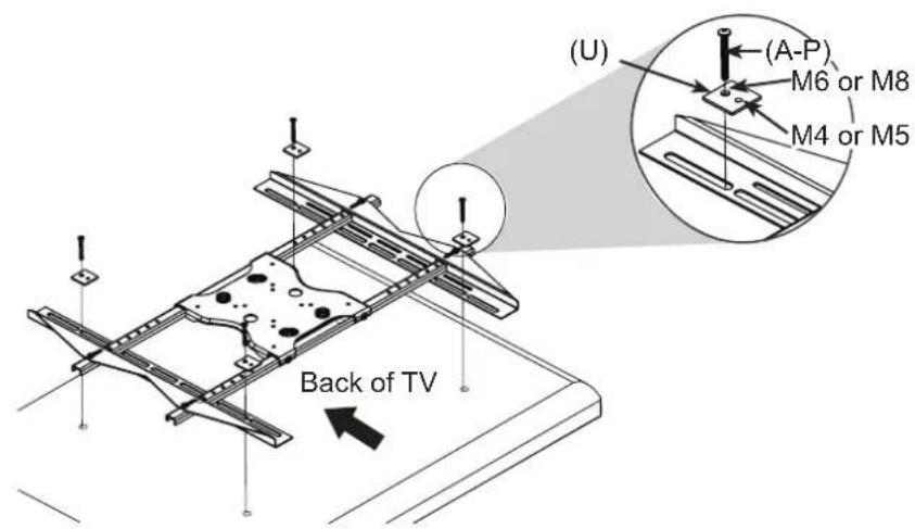
text_image
(U) (A-P) M6 or M8 M4 or M5 Back of TVAttach TV to Arm Assembly
ATTENTION: This procedure requires two persons to perform. The instructions in this step are the same for all TV sizes.
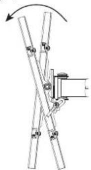
- Pull the head of the arm assembly out from the wall and move the tilt adjustment down as much as possible. (Fig.4)
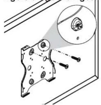
- Insert two bolts (BB) into the top two holes of the TV adapter plate. Leave approximately 1/4" of exposed thread (do not fully tighten). (Fig.5)
- Lift the display and hook it over the mounting head by lowering the exposed portion of the top screws into the open key slots on top of the arm assembly head. (Fig.6)
- Insert two bolts (BB) through the bottom two holes of the assembly head and thread them into the adapter plate. (Fig.7)
- Fully tighten all four bolts (BB). Tilt the TV up and down while watching the back to make sure that all 4 bolts are fully tightened.
Figure 4
natural_image
Diagram of a mechanical linkage system with rotating arm and mounting bracket (no text or symbols)Figure 5 Figure 6 Figure 7
natural_image
Technical illustration of a mechanical component with a magnified inset showing internal features (no text or symbols)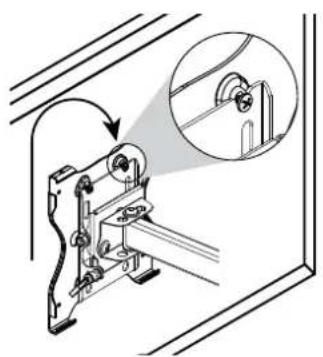
natural_image
Technical line drawing of a mechanical device with an inset showing a close-up view of a component (no text or symbols present)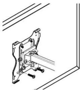
natural_image
Technical line drawing of a mechanical clamp or bracket assembly (no text or symbols)Cable Cover Attachment
Route the electrical and data cables along the arm assembly and secure in place using the provided cable covers (Fig.8).
NOTE: Ensure enough slack is provided to allow for vertical and horizontal move before attaching the cable covers.
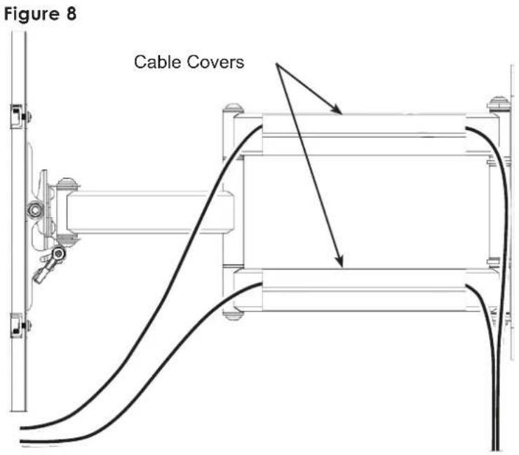
text_image
Figure 8 Cable CoversAdjustments
Tilt Adjustment
Loosen the tilt levers on the head of the arm assembly enough to allow controlled adjustment. Set the desired tilt, then re-tighten the locking levers. (Fig.9)
Once the tilt levers are locked, their position can be adjusted by pulling out on each lever and rotating it to a less obtrusive position.
Horizontal Adjustment
Slightly loosen the two screws on the head of the arm assembly using the provided Hex key (Fig.9). Then, firmly hold the TV by two opposite corners and gently turn it into the desired position (Fig.10). When level, re-tighten the screws.

text_image
Figure 9 15° 6° Cable Covers Horizontal Level Adjustment Screws Tilt Lever (1 on each side)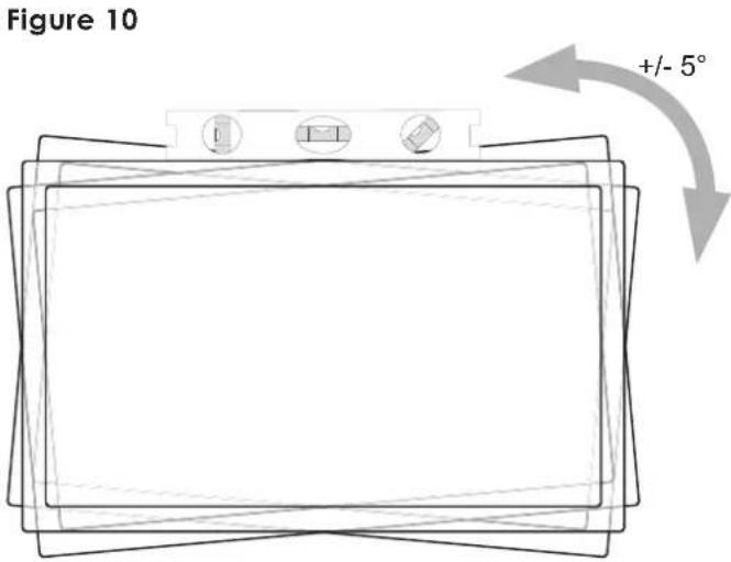
text_image
Figure 10 +/- 5°Lifetime Limited Warranty
SunbriteTV™ Mounts have a Lifetime Limited Warranty. This warranty includes parts and labor repairs on all components found to be defective in material or workmanship under normal conditions of use. This warranty shall not apply to products which have been abused, modified or disassembled. Products to be repaired under this warranty must be returned to SunbriteTV or a designated service center with prior notification and an assigned return authorization (RA) number.
Technical Support 866.838.5052