SB-WM-T-L-BL - Wall mount SunBriteTV - Free user manual and instructions
Find the device manual for free SB-WM-T-L-BL SunBriteTV in PDF.

User questions about SB-WM-T-L-BL SunBriteTV
0 question about this device. Answer the ones you know or ask your own.
Ask a new question about this device
Download the instructions for your Wall mount in PDF format for free! Find your manual SB-WM-T-L-BL - SunBriteTV and take your electronic device back in hand. On this page are published all the documents necessary for the use of your device. SB-WM-T-L-BL by SunBriteTV.
USER MANUAL SB-WM-T-L-BL SunBriteTV
True Outdoor Television
Weatherproof Universal Fixed and Tilt Mounts For Large Displays

INSTALLATION MANUAL
WARNINGS:
• Installation by a qualified professional is highly recommended for this product.
- Do not begin installation until you have thoroughly read and understand these instructions.
- This mount fits displays up to VESA 700mm x 500mm and supports a maximum load of 165 lbs (75 kg).
- Ensure the mounting wall will safely support four times the combined weight of the mount and display panel.
- The manufacturer does not accept responsibility for incorrect installation.
SPECIFICATIONS:
• Maximum Load: 165 lbs. (75 kg)
• Forward Tilt Range: -8°/+13°
• Horizontal Tilt Range: ±5°
- Weather Resistant Coating
• Stainless Steel Mounting Hardware
TOOLS REQUIRED:
- Power Drill
- 5/16" and 1/4" Drill Bit
• Phillips Head Screw Driver - Level
- Socket Wrench
BOX CONTENTS:
- Wall Plate (1)
- Arm left (1)
- Arm right (1)

with 1/2" Socket head
CAUTION:
This wall mount is intended for use only with the maximum weight of 165 lbs (75kg).

HARDWARE KIT
Bag 1
(A) M4x10 Bolt (x4)

(B) M4x20 Bolt (x4)
(C) M4x30 Bolt (x4)

(D) M4x40 Bolt (x4)
Bag 2

(E) M5x10 Bolt (x4)

(F) M5x20 Bolt (x4)
(G) M5x30 Bolt (x4)
(H) M5x40 Bolt (x4)
Bag 3

(1) M6x10 Bolt (x4)
(J) M6x20 Bolt (x4)
(K) M6x30 Bolt (x4)
(L) M6x40 Bolt (x4)
Bag 4
(M) M8x10 Bolt (x4)

(N) M8x20 Bolt (x4)
(O) M8x30 Bolt (x4)

(P) M8x40 Bolt (x4)
Bag 5

(Q) M4/M5
on Spacer (x8)

(R) M6/M8
Nylon Spacer (x8)

(S) M5 Washer (x16) (T) M8 Washer (x8)

Bag 6
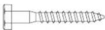
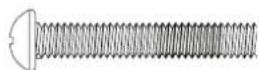
(U) M8x63
Lag Bolt (x6)

(V) Lag Bolt Washer (x6)
PACKAGE CONTENTS:
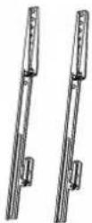
Arms
With Tilt)
Arms
(With Fixed)
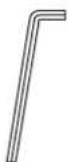
Allen Key (x1)
Bag 7
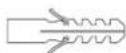
(W) Concrete Anchor (x6)
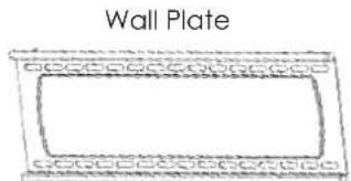
natural_image
Simple line drawing of a wall plate with decorative border (no text or symbols)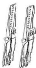
INSTALLATION:
Step 1: Mount the Wall Bracket Assembly
For Mounting on a Stud Wall
a. Pre-drill holes into two wood studs using a 1/4" drill bit. Be sure to drill into the center of the studs at least 2-1/2" deep. The use of a stud finder is highly recommended.
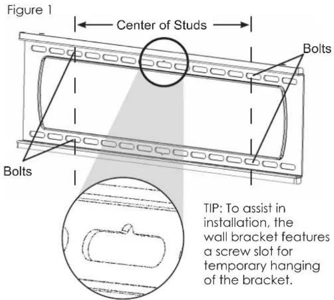
b. Insert four Lag Bolts (U) into holes through the Wall Plate and tighten down. (Figure 1)
WARNING: Tighten bolts so that wall plate is firmly attached, but do not overtighten. Overtightening can damage the bolts, greatly reducing their holding strength.
For Mounting on a Concrete Wall
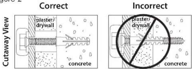
a. Pre-drill holes into concrete using 5/16" drill bits to a depth of 2 1/2". Insert concrete wall anchors (W) and tap in with hammer, if necessary (Figures 2 & 3).
WARNING: When installing wall arm assembly on cinder block, verify first that you have a minimum of 1-3/8" of concrete thickness to be used for the concrete anchors. Do not drill into mortar joints! Be sure to mount in a solid part of the block, generally 1"minimum from the side of the block. Cinder block must meet ASTM C-90 specifications. It is suggested that a standard electric drill on slow setting is used to drill the hole instead of a hammer drill to avoid breaking out the back of the hole when entering a void or cavity.
Concrete must be 2000 psi density minimum. Lighter density concrete may not hold concrete anchor.
Make sure that the supporting surface will safely support the combined load of the equipment and all attached hardware and components.
b. Insert four Lag Bolts (U) into the wall anchors (W) through the Wall Plate. Tighten all bolts.
WARNING: Tighten bolts so that wall plate is firmly attached, but do not overtighten. Overtightening can damage the bolts, greatly reducing their holding strength.
Step 2: Mount Arms to TV
a. Determine the diameter of the screw (parts A through P) your TV requires by carefully trying to hand-thread one into the threaded insert on the rear of the TV. If there is any resistance, stop immediately.
b. Thread the screw through the washer (Q or R), arm, spacer (S or T), and into the TV.
Note: Spacers are commonly needed on TVs with curved backs or recessed screw inserts.
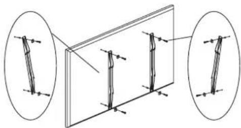
c. Ensure the arms are installed flat side to TV and are square to each other after all screws have been installed (Figure 4).
text_image
Figure 1 Center of Studs Bolts Bolts TIP: To assist in installation, the wall bracket features a screw slot for temporary hanging of the bracket.Figure 2
text_image
Correct Plaster/ drywall Concrete Incorrect plaster/ drywall ConcreteFigure 3

text_image
Drill holes and insert anchors. Place wall arm assembly plate over anchor and secure with lag bolt. Tighten all lag bolts. Concrete Wall Wall Arm Lag BoltFigure 4
natural_image
Diagram showing two views of a rectangular panel with internal vertical supports, no text or symbols presentStep 3: Hang TV on to the Wall Plate
a. Carefully lift the TV to hook the arms over the top lip of the wall plate. Allow the lower portion of the arms to swivel in under the bottom lip of the wall plate. Do not release the TV until it is completely connected to the wall plate.
Adjustments:
Adjust Horizontal Level and Tilt
Forward Tilt Adjustment (SB-WM-T-L-BL)
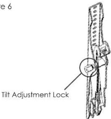
a. Using the included long Allen key, loosen the tilt adjustment locks on the sides of the arms enough to allow movement.
b. Set the tilt to the desired angle, then re-tighten the locks. If the locks cannot be tightened enough, remove the TV from the wall for better access.
Horizontal Adjustment
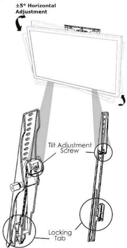
a. If display is not horizontally level when mounted, Tilt Adjustment Screws are included at the top of each arm for micro-adjustments (Figure 7). Use provided Allen Key to raise or lower the screw, which will in turn raise or lower the mount.
Note: Due to display weight, it may be easier to lift panel slightly when adjusting the screw. Caution should be taken to avoid any slips or drops to avoid damage and/or injuries.
Locking
a. To lock the arms to the wall bracket, twist the locking tabs until the edge catches behind the bracket. The Allen Key can be used as a tool to help with this step. Padlock is optional (not included).
Figure 5

natural_image
Two people pointing at a blank whiteboard (no text or symbols visible)Figure 6
text_image
e 6 Tilt Adjustment LockFigure 7
text_image
±5° Horizontal Adjustment Tilt Adjustment Screw Locking TabLifetime Limited Warranty
SunbriteTV™ Mounts have a Lifetime Limited Warranty. This warranty includes parts and labor repairs on all components found to be defective in material or workmanship under normal conditions of use. This warranty shall not apply to products which have been abused, modified or disassembled. Products to be repaired under this warranty must be returned to SunbriteTV or a designated service center with prior notification and an assigned return authorization (RA) number.
Technical Support 866.838.5052