SB-WM-ART1-S-BL - Wall mount SunBriteTV - Free user manual and instructions
Find the device manual for free SB-WM-ART1-S-BL SunBriteTV in PDF.

User questions about SB-WM-ART1-S-BL SunBriteTV
0 question about this device. Answer the ones you know or ask your own.
Ask a new question about this device
Download the instructions for your Wall mount in PDF format for free! Find your manual SB-WM-ART1-S-BL - SunBriteTV and take your electronic device back in hand. On this page are published all the documents necessary for the use of your device. SB-WM-ART1-S-BL by SunBriteTV.
USER MANUAL SB-WM-ART1-S-BL SunBriteTV
True Outdoor Television
SB-WM-ART1-S-BL
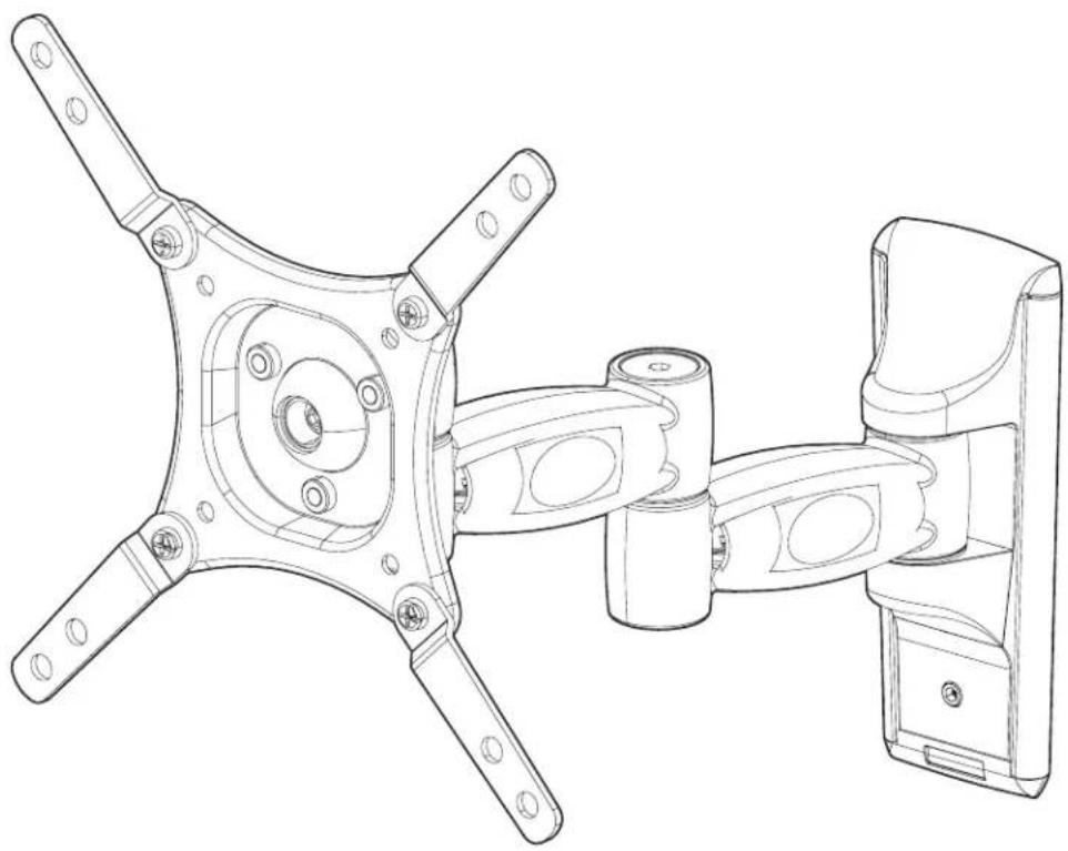
Weatherproof Universal Single-Arm Articulating Mount for Small Displays
natural_image
Technical line drawing of a mechanical assembly with four arms and mounting holes (no text or symbols)SPECIFICATIONS
• Weather Resistant Coating
- Tilt Range: +/- 13.8°
• Stainless Steel Mounting Hardware
• Pan/Swivel Range: 180°
• Maximum Load: 50 lbs (22.68 kg)
• Horizontal Rotation: 360°
• VESA Patterns: 75x75, 100x100, 200x200
• Extension/Profile: 3.7" to 15.2" (9.5 to 38.5 cm)
WARNINGS
- Make sure these instructions are read and thoroughly understood before attempting installation. If you are unsure of any part of the installation process, contact a professional installer for assistance.
- The wall or mounting surface must be capable of supporting the combined weight of the mount and the display; otherwise the structure must be reinforced.
- Safety gear and the proper tools must be used. Failure to do so can result in property damage and/or serious injury.
- Follow all instructions and recommendations regarding adequate ventilation and suitable locations for mounting your display. Consult the owner's manual for your display for information.
TOOLS REQUIRED
• Phillips Head screwdriver
• Electric or Portable Drill
• 3/16" (5mm) Drill Bit and Stud finder for Drywall Installation
- 5/16" (8mm) Masonry Bit for Concrete Installation

CAUTION: This wall mount is intended for use only with maximum weight of 50 lbs (22.68 kg).
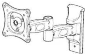
BOX CONTENTS
Not Pictured: Manual (1)
natural_image
Technical line drawing of a mechanical assembly with mounting flanges and housing (no text or symbols)Wall Mount Assembly (1)
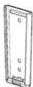
Wall Plate (1)

200x200 VESA Adapter Arms (4)

Adapter Arm Hardware
M6x12 Bolts w/ Nuts (4 ea.)
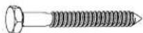
Lag Screws (2)

Concrete Anchors
(2)

Hex Keys
4mm (1)
6mm (1)
Security Keys
4mm (1)
5mm (1)
6mm (1)
TV Mounting Hardware
(Extra parts are included to ensure compatibility with your TV. Not all of this hardware will be used.)

10mm Long Screws
-M4×10 (4)
-M5×10 (4)
-M6×10 (4)

Black M5 Washer (16)
16mm Long Screws
-M4x16 (4)
-M5x16 (4)
-M6x16 (4)

Black M8 Washer (8)

20mm Long Screws
-M4×20 (4)
-M5×20 (4)
-M6×20 (4)

Black Nylon Washer (4)

30mm Long Screws
-M4x30 (4)
-M5×30 (4)
-M6x30 (4)
INSTALLATION
1-1. Installing the Wall Plate (Drywall)
IMPORTANT! For safety reasons, this mount must be secured to a wood stud capable of supporting the combined weight of the mount and display.
A. Use a high quality stud finder to locate a single stud where you want to install your mount.
B. Mark both edges of the stud to help identify the exact center (see illustration to the right).
C. Place the wall plate over the center of the marked stud and level it using the integrated bubble level.
D. Mark the two holes for securing the mount and set wall plate aside.
E. Drill a pilot hole at each marked location using an electric or portable drill and 3/16" (5 mm) bit.
F. Move the wall plate back into position and secure it using the lag screws from the hardware kit. Do not over-tighten the screws.
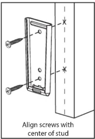
text_image
Align screws with center of stud1-2. Installing the Wall Plate (Concrete)
IMPORTANT! For safety reasons, the concrete wall must be capable of supporting the combined weight of the mount and display.
A. Place the wall plate in the desired location, using the built-in bubble to level it.
B. Mark the two holes for securing the mount and set the wall plate aside.
C. Drill a 5/16" (8 mm) hole at both marked locations. Remove any excess dust from the holes.
D. Insert a concrete anchor into each hole so that it is flush with the concrete surface. A hammer can be used to lightly tap the anchors into place if necessary.
NOTE: If the concrete wall is covered by a layer of plaster or drywall, the concrete anchor must pass completely through the layer to rest flush with the concrete surface.
E. Move the wall plate back into position and secure it using the lag screws from the hardware kit. Do not over-tighten the screws.
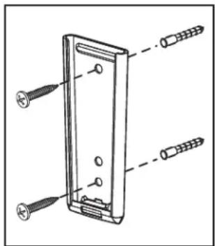
text_image
Technical diagram of a device with labeled screw and nut components2. Attaching the Mount to the Display
IMPORTANT! Avoid placing your display face down as it may damage the viewing surface. Use care when handling your display! NOTE: Different bolt lengths are included to accommodate a wide variety of displays. Not all included hardware will be used.
A. Determine the VESA pattern of your display. If necessary, attach adapter arms for 200x200 using M6 security bolts and lock nuts.
B. Determine the correct bolt to use by examining the back of your display:
- If the back of your display is flat and the mounting holes are flush with the surface, you will use one of the 10 mm length bolts from the TV mounting hardware kit.
- If the back of your display is curved, has a protrusion, or if the mounting holes are recessed, use the longer bolts and spacers. Use the shortest screw possible to avoid damage to the display from protrusion through the mounting hole.
C. Attach the mount to the back of your display using the matching hardware. Do not over-tighten the screws.
NOTE: If the holes of the mount do not line up with the holes on your display, check to make sure that your display is VESA compatible. This mount can only be used with displays that are VESA 75, 100, or 200 compatible.
3. Final Assembly
A. Hold the display assembly over the wall plate and slide the mount into the wall plate.
B. To remove, carefully slide the mount upwards and out of the wall plate.
C. For extra security and stability, tighten the set screw located on the wall plate (see illustration to the right) using the included hex key. Remember to loosen the set screw before attempting to remove the mount form the wall.
D. To use the integrated cable management feature, first remove the plastic covers located on the arms of the mount. Route your cables through the arms and re-attach the plastic covers to hold them in place. Make sure to leave enough slack in the cables so that they are not pulled or pinched when you move the mount. You may also route the cables through the hook located at the bottom of the wall plate.

natural_image
Technical line drawing of a mechanical assembly with mounting holes and a vertical component (no text or symbols)
natural_image
Technical line drawing of a mechanical component with no visible text or symbolsOPERATION AND ADJUSTMENT
- 6 adjust the tilt angle or rotate your screen, firmly grasp the sides of your display and carefully move it into position. If you find the mount is too difficult to move or is too loose to hold your TV in position, adjust the three screws located directly behind the head of the mount using the included security key (see illustration to the right). Tighten the screws evenly once positioned.
- Swivel adjustments can be made by moving your display into the desired position. The swivel joints can be adjusted using the included hex key (see illustration to the right).

natural_image
Technical line drawing of a mechanical component with arrows indicating assembly or force direction (no text or symbols)
natural_image
Mechanical assembly diagram showing a bracket with mounting holes and a downward arrow indicating a component (no text or symbols present)LIFETIME LIMITED WARRANTY
SunBriteTV® Mounts have a Lifetime Limited Warranty. This warranty includes parts on all components found to be defective in material or workmanship under normal conditions of use. This warranty shall not apply to products which have been abused, modified or disassembled. Products to be repaired under this warranty must be returned to SunBriteTV or a designated service center with prior notification and an assigned return authorization (RA) number.
Technical Support 866.838.5052