SB-CM-T-L-BL - Télévision extérieure SunBriteTV - Free user manual and instructions
Find the device manual for free SB-CM-T-L-BL SunBriteTV in PDF.

User questions about SB-CM-T-L-BL SunBriteTV
0 question about this device. Answer the ones you know or ask your own.
Ask a new question about this device
Download the instructions for your Télévision extérieure in PDF format for free! Find your manual SB-CM-T-L-BL - SunBriteTV and take your electronic device back in hand. On this page are published all the documents necessary for the use of your device. SB-CM-T-L-BL by SunBriteTV.
USER MANUAL SB-CM-T-L-BL SunBriteTV
True Outdoor Television
SB-CM-T-L-BL
SB-CM-DT-L-BL
Weatherproof Universal Single & Dual Ceiling Mount for Large TVs

natural_image
Two vertical black bars with small gray bars at the bottom, against a white background (no text or symbols)
WARNING
• We highly recommend this product be installed by a qualified professional.
- Please do not begin installation until you have thoroughly read and understood these instructions.
- This mount supports display mounting from VESA 200x200 up to 700X500.
• This mount supports a maximum load of 175 lbs (79.5 kg).
- Ensure the ceiling will safely support the combined weight of the mount and your chosen display.
- The manufacturer does not accept responsibility for incorrect installation.

CAUTION:
These ceiling mounts are intended for use only with the maximum weight of 175 lbs (79.5 kg).
SPECIFICATIONS BOX CONTENTS TOOLS REQUIRED
• Maximum Load: 175 lbs (79.5 kg)
- Extension: 18 inches
• Stainless Steel Mounting Hardware
• Pan/Swivel Range: 360°
- Tilt Range: +0" / -20"
- Weather Resistant Coating
• VESA patterns: 200x200 up to 700X500
• Ceiling Plate Assembly (1)
- Mounting Head (1)
- Adapter Plate (1/2)
• TV Arms (2/4)
- 18" Fixed Extension Pole (1)
- Hardware Kit (1)
- Power Drill
- 3/16" (5mm) Drill Bit
- 5/16" (8mm) Masonry Bit
• 1/2" (13mm) Wrench
• Phillips Head Screw Driver
• 3/8" Socket Wrench - 7/16" Socket Wrench
HARDWARE KIT CONTENTS

M4 x 12mm Philips
M4 x 20mm Philips

Allen Wrench 2.5mm,

Allen Wrench,
INSTALLATION
Step 1: Mark Mounting Hole Locations
Place the ceiling plate on the mounting surface and mark the mounting hole locations.
Step 2: Mount the Ceiling Plate
For Mounting on a Wood Joist (Fig 1)
a. Drill four holes into joist using a 3/16" drill bit. Be sure to drill into the center of the joists.
b. Insert four lag screws into holes through the ceiling plate and tighten down.
WARNING: Tighten screws so that the ceiling plate is firmly attached, but do not over tighten. Over-tightening can damage the screws, greatly reducing their holding strength.

text_image
Fig 1 DFor Mounting on a Concrete Ceiling (Fig 2)
NOTE: Concrete anchors not provided. 5/16" x 2-1/2" Red Head® Hex Sleeve Anchors, #50113, are recommended for concrete or cinder block installation.
WARNING: When installing ceiling plate on cinder block, verify first that you have a minimum of 1-3/8" of concrete thickness to be used for the concrete wall anchors (not included). Do not drill into mortar joints! Be sure to mount in a solid part of the block, generally 1"minimum from the side of the block. Cinder block must meet ASTM C-90 specifications. It is suggested that a standard electric drill on slow setting is used to drill the hole instead of a hammer drill to avoid breaking out the back of the hole when entering a void or cavity.
Concrete must be 2000 psi density minimum. Lighter density concrete may not hold anchor.
a. Drill four holes into concrete using 5/16" masonry bit. Insert hex sleeve anchors (not supplied) and insert per instructions included with wall anchors.
b. Remove washer and nut from end of bolt from all four anchor studs. Place ceiling plate over bolts so they align with the four holes in ceiling

text_image
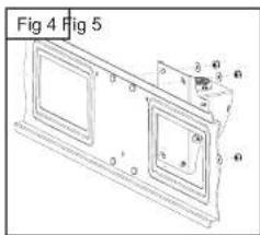
Fig 2Step 4: Attach the Mount Head
a. Inserting through-bolts on adapter plate through angled slots in mounting head. Place M8 washers and nylock nuts on end of through bolts and tighten down (Fig 4).
b. Screw mount head on to end of extension pole and tighten set screws (Fig 5).
Step 5: Attach the TV Arms to the Display
Attach the TV arms to the display using M4, M5, M6, or M8 screws. For displays with a hole pattern in a pocket or inputs behind adapter plate, spacers go between TV arms and display (Fig 6).
Step 6: Attach the Display to the Ceiling Mount Assembly
a. Lift the display and hang it on the wall arm assembly by the TV arms, ensuring all 3 hooks slide into holes of mount head (Fig 7).
b. Using a Philip's screwdriver, tighten down locking screws at the bottom of each TV arm, ensuring that the screws hold the arms captive to the bracket (Fig 8).
c. Insert locking pin (Fig 9).
ADJUSTMENTS
Tilt Adjustment
a. Loosen screws on side of mount head (only enough to allow controlled adjustment).
b. Adjust tilt forward or backward.
c. Retighten screws, then check to ensure that tilt angle is locked in place.
Horizontal Adjustment (Roll)
a. Slightly loosen all 4 nylock nuts behind adapter plate only to allow movement of the plate.
b. Using the corners of the TV, adjust left/right until level. Re-tighten all nylock nuts.
WARNING: Completely loosening and/or removing nuts may
text_image
Fig 4 Fig 5

natural_image
Technical line drawing of a mechanical assembly with two components and dimension lines (no text or symbols)
natural_image
Diagram showing two rectangular panels with vertical bars and an arrow indicating direction, labeled 'Fig 7' (no text or symbols on the panels themselves)