WAP-8101 - Access Point LEVELONE - Free user manual and instructions
Find the device manual for free WAP-8101 LEVELONE in PDF.

| Product Type | Wireless Access Point |
| Brand | LevelOne |
| Model | WAP-8101 |
| Dimensions (W x D x H) | 17.5 x 12.5 x 3.5 cm (6.9 x 4.9 x 1.4 in) |
| Weight | Approximately 300 g (10.6 oz) |
| Power Supply | DC 12V, 0.5A |
| Power Consumption | 6W (max) |
| Wireless Standards | IEEE 802.11n/g/b |
| Maximum Data Rate | 300 Mbps |
| Frequency Band | 2.4 GHz |
| Antennas | 2 external dipole antennas (3 dBi each) |
| Network Ports | 1 x 10/100 Ethernet (RJ-45) with PoE support (802.3af) |
| Security | WEP, WPA, WPA2, WPA2-PSK |
| Management | Web-based GUI, SNMP |
| Operating Temperature | 0°C to 40°C (32°F to 104°F) |
| Operating Humidity | 10% to 90% (non-condensing) |
| Mounting | Wall or ceiling mountable (bracket included) |
| Maintenance | Clean with a soft, dry cloth; avoid liquids and abrasive cleaners |
| Spare Parts & Repairability | Not user-serviceable; contact LevelOne support for repairs |
| General Information | Indoor use only, designed for small to medium environments |
Frequently Asked Questions - WAP-8101 LEVELONE
User questions about WAP-8101 LEVELONE
0 question about this device. Answer the ones you know or ask your own.
Ask a new question about this device
Download the instructions for your Access Point in PDF format for free! Find your manual WAP-8101 - LEVELONE and take your electronic device back in hand. On this page are published all the documents necessary for the use of your device. WAP-8101 by LEVELONE.
USER MANUAL WAP-8101 LEVELONE
text_image
level® oneLevelOne User Manual
WAP-8101
Managed Ceiling Wireless Access Point, 1200Mbps, 802.11a/b/g/n/ac, Gigabit Ethernet, PoE 802.3af
Table of contents
CHAPTER 1 INTRODUCTION....5
1.1 CONTENTS LIST 5
1.2 HARDWARE INSTALLATION 6
1.2.1 WARNING....6
1.2.2 SYSTEM REQUIREMENTS....6
1.2.3 Hardware Configuration 7
1.2.4 Mounting on the Ceiling / Wall....8
1.2.5 LED Indicators.... 10
1.2.6 Button Definition 11
CHAPTER 2 GETTING STARTED .... 14
2.1 EASY SETUP VIA WEB UI 15
2.2 USE WEC BUTTON TO SETUP WIRELESS PROFILES 18
2.2.1 One Master and several isolated Slaves.... 19
2.2.2 One Master and a series of connected Slaves 21
CHAPTER 3 MAKING CONFIGURATIONS....24
3.1 BASIC NETWORK 26
3.1.1 Ethernet LAN 26
3.1.2 Wireless.... 27
3.1.2.1 Wireless Setup 28
3.1.2.1.1 AP Only Mode 28
3.1.2.1.2 WDS Hybrid Mode....32
3.1.2.1.3 WDS Only Mode 35
3.1.2.1.4 Universal Repeater Mode....37
3.1.2.2 Advanced Wireless Setup 40
3.1.2.2.1 Advanced RF Module1 Settings....40
3.1.2.2.2 Advanced RF Module2 Settings....41
3.1.3 IPv6 43
3.2 ADVANCED NETWORK 44
3.2.1 Firewall 44
3.2.1.1 MAC Address Control 44
3.2.2 Management 45
3.2.2.1 UPNP 45
3.2.2.2 SNMP 45
3.3 SYSTEM....48
3.3.1 System Information 48
3.3.2 System Status 49
3.3.2.1 Web Log....49
3.3.2.2 Syslog 49
3.3.2.3 Email Alert....50
3.3.3 System Tools....50
3.3.3.1 Change Password....50
3.3.3.2 FW Upgrade....51
3.3.3.3 System Time 52
3.3.3.4 Others 53
3.3.4 MMI 54
3.3.4.1 Web UI....54
CHAPTER 4 TROUBLESHOOTING....55
APPENDIX A. ASSIGNING A STATIC IP IN WINDOWS PC....59
APPENDIX B. LICENSING INFORMATION 67
Copyright
The contents of this publication may not be reproduced in any part or as a whole, stored, transcribed in an information retrieval system, translated into any language, or transmitted in any form or by any means, mechanical, magnetic, electronic, optical, photocopying, manual, or otherwise, without the prior written permission.
Trademarks
All products, company, brand names are trademarks or registered trademarks of their respective companies. They are used for identification purpose only. Specifications are subject to be changed without prior notice.
FCC Interference Statement
This equipment has been tested and found to comply with the limits for a Class B digital device pursuant to Part 15 of the FCC Rules. These limits are designed to provide reasonable protection against radio interference in a commercial environment. This equipment can generate, use and radiate radio frequency energy and, if not installed and used in accordance with the instructions in this manual, may cause harmful interference to radio communications. Operation of this equipment in a residential area is likely to cause interference, in which case the user, at his own expense, will be required to take whatever measures are necessary to correct the interference.
CE Declaration of Conformity
This equipment complies with the requirements relating to electromagnetic compatibility, EN 55022/A1 Class B.
Chapter 1 Introduction
Congratulations on your purchase of this outstanding product: WAP-8101 1200Mbps 802.11ac Ceiling Wireless Access Point are designed for small- and medium-sized businesses to extend the existing wired networks and has the ability to operate in different modes and can be used in a wide variety of wireless applications like AP, Point-to-Point. Universal
Repeater Mode not only has an easier setup method, but also provides better performance and compatibility to create a virtually larger wireless network infrastructure by linking up other access points.
Support Multiple-SSID capability to use one Physical AP to simultaneously emulate 8 APs with different ESSIDs by separate their packets via VLAN technology.
1.1 Contents List
| Items | Description | Contents | Quantity |
| 1 | WAP-8101 |  | 1pce |
| 2 | Power Adapter |  | 1pce |
| 3 | RJ45 Cable |  | 1pce |
| 4 | CD |  | 1pce |
1.2 Hardware Installation
1.2.1 WARNING

Attention
- Do not use the product in high humidity or high temperatures.
- Do not use the same power source for the Product as other equipment. Only use the power adapter that comes with the package. Using a different voltage rating power adaptor may damage the device.
- Do not open or repair the case yourself. If the Product is too hot, turn off the power immediately and have it repaired at a qualified service center.
- Place the Product on a stable surface and avoid using this product and all accessories outdoors.
1.2.2 SYSTEM REQUIREMENTS
| Network Requirements | An Ethernet-based Cable or DSL modemIEEE 802.11a/ b/g/n/ac wireless clients10/100/1000 Ethernet |
| Web-based Configuration Utility Requirements | Computer with the following:Windows®, Macintosh, or Linux-based operating systemAn installed Ethernet adapterBrowser Requirements:Internet Explorer 6.0 or higherChrome 2.0 or higherFirefox 3.0 or higherSafari 3.0 or higher (with Java 1.3.1 or higher)Windows® Users: Make sure you have the latest version of Java installed. Visit www.java.com to download the latest version. |
| CD Installation Wizard Requirements | Computer with the following:Windows® 7, Vista®, or XP with Service Pack 2An installed Ethernet adapterCD-ROM drive |
1.2.3 Hardware Configuration
Rear View:
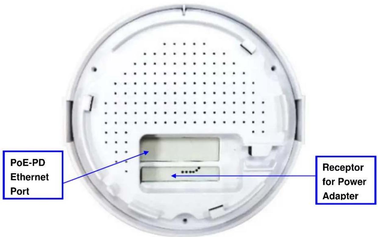
text_image
PoE-PD Ethernet Port Receptor for Power Adapter1.2.4 Mounting on the Ceiling / Wall
This device is designed for easily mounted on the ceiling or wall with a simple mount bracket. Before mounting it to the expected location, please make proper configuration for the device setting and run the PoE Ethernet cable to the location in advance.
The following illustrations show you how to mount this device on the ceiling / wall.
| Description | Illustration | |
| A | 1. Drill 2 holes for wall plugs.Self-tapping screws (Diameter : 3mm)If you run the cable above the ceiling (invisible cabling), you have to drill another big hole (about 10~20 mm diameter) to pull out the cable for connecting to the device.2. Screw the mounting bracket on the ceiling / wall. | 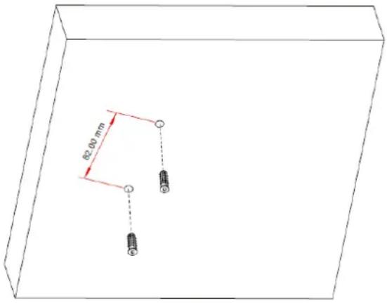  |
| B | 1. Drill 2 holes for wall plugs.Self-tapping screws (Diameter : 3.5 mm)If you run the cable above the ceiling (invisible cabling), you have to drill another big hole (about 10~20 mm diameter) to pull out the cable for connecting to the device.2. Screw the mounting bracket on the ceiling / wall. | 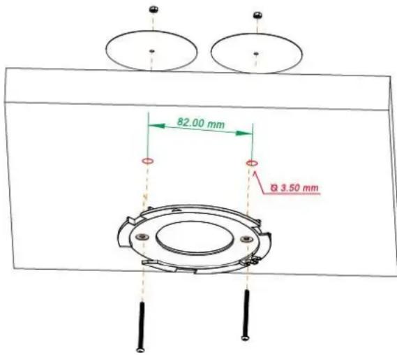 |
| C | Plug-in the cable (Ethernet cable, Power cord) to the connectors in the button side.Run the cables upward to proper location. |  |
| D | Attached this device to mounting bracket by rotating it clock wisely to click into place. | 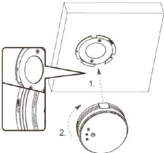 |
| E | Installation completed. |  |
1.2.5 LED Indicators

text_image
level one WEC/Reset Status WiFi LAN| LED | Description |
| Status | 1. When the device is booted up and ready:2. When WEC/Reset is triggered (with button pressed):Status LED flashes at different rate according button-pressed duration.Stage 1 (1 ~ 5 sec) : Flash very fastStage 2 (6 ~ 10 sec) : Flash twice per secondStage 3 (11~15 sec) : Flash once per secondStage 4 (16~30 sec) : Solid Green |
| OFF: The device is powered off. | |
| WiFi | Green LED : Device is in Master ModeAmber LED: Device is in Slave ModeLED flash: data packet transferred.LED in fast flash per second during 2min: WPS PBC statusOFF: Wireless Radio is disabled.LED in slow flash or Flash Green and Amber Alternately : Wireless Connection doesn't establish.LED in Solid: Wireless Connection established successfully.※ WiFi LED flashes or not depends as the configuration of RF Module2(5GHz). |
| LAN | OFF: No Ethernet connection.Solid Green: Ethernet connection is linked up.Flash Green: Data packet is transferred over the Ethernet link. |
1.2.6 Button Definition
There is one multi-function push button “WEC/Reset” in this device. According to different button pressed duration, the device will take specific reaction. For ease of interacting with the device, you can also check the Status and WiFi LED to determine when to release the button. The Reset/WEC button’s behavior is defined below:
| Function | Button | Description |
| EasyConfiguration(Master to Slave) | WEC/Reset(Press 3 sec) | There are two alternative AP modes defined for the device to operate with WEC (Wireless Easy Connection) feature. One is Master Mode (by default), and the other is Slave Mode.Please manually configure the Wireless Setting for the Master AP through web UI first, and also prepare a Slave AP that already been set to Slave Mode.1. Press the WEC/Reset button of the Master AP for 1~3 seconds, release it to trigger the WEC process. Then, WiFi Green LED flashes fast.2. Press the WEC/Reset button of the Slave AP for 1~3 seconds, release it to trigger the WEC process. Then, WiFi Amber LED flashes fast.Note: The Slave AP must be an un-configured one, if it has already been paired and configured before, please reset its Slave configuration first.3. After a few seconds (normally about 30~60 seconds). The Master and Slave APs can be paired automatically, and auto-duplicates the VAP1 wireless setting of the Master AP as that of the Slave AP.(If there is something wrong during paring the two devices, the process will be finished in 2 minutes.)4. Once the easy configuration process completed, the Status LED will be recovered to its original behavior (prior to you triggered it) And the WiFi LED will be Solid when Slave AP is connected to the network. |
| Easy | WEC/Reset | Besides the above “Master to Slave” configuration, |
| Configuration(Slave to Slave) | (Press 3 sec) | the easy configuration process also supports “Slave to Slave” configuration.1. Press the WEC/Reset button of the first Slave AP (say Slave1 that has been paired and configured) for 1~3 seconds, release it to trigger the WEC process. Then, the WiFi LED flashes fast.2. Press the WEC/Reset button of the second Slave AP (say Slave2 that is an un-configured Slave AP) for 1~3 seconds, release it to trigger the WEC process. Then, the WiFi LED flashes fast.3. After a few seconds (normally about 30~60 seconds). The Slave1 and Slave2 APs can be paired automatically, and auto-duplicates the wireless setting of the Slave1 as that of the Slave2.(If there is something wrong during paring the two devices, the process will be finished in 2 minutes.)Once the easy configuration process completed, the Status LED will be recovered to its original behavior (prior to you triggered it). |
| AP Mode Toggling | WEC/Reset(Press 8 sec) | There are two alternative AP modes defined for the device to operate with WEC (Wireless Easy Connection) feature. One is Master Mode (by default), and the other is Slave Mode.To change the AP mode from one to the other, you have to:1. Press the WEC/Reset button for 6~10 seconds, and then release it.2. The WiFi LED becomes OFF in 3 ~ 5 seconds,3. After about 20 ~ 25 seconds, the WiFi LED will be lit ON again to indicate that the AP Mode is changed.It takes about 36 seconds to change (toggle) the AP Mode completely.WiFi Green LED : Device is in Master ModeWiFi Amber LED: Device is in Slave Mode |
| Reset Slave AP | WEC/Reset | 1. Press the WEC/Reset button for about 11~15 |
| Configuration | (Press 13 sec) | seconds and release it.2. The Slave AP will be marked as an un-configured device, so that it can be paired with another Master or configured Slave AP later.For Master AP, there is no effect on this button behavior. |
| Reset to Default | WEC/Reset (Press 20 sec) | 1. Press the Reset/WEC button for about 20 seconds till the Status LED becomes solid Green to indicate that the reset to default function is triggered. Release the button.2. Then, the device will reboot automatically and apply the factory default settings as well.It takes about 2 minutes to finish the reset to factory default operation. |
Chapter 2 Getting Started
Before you can install this product to designated location and make it operate properly, you have to configure the device setting to fit in your network environment.
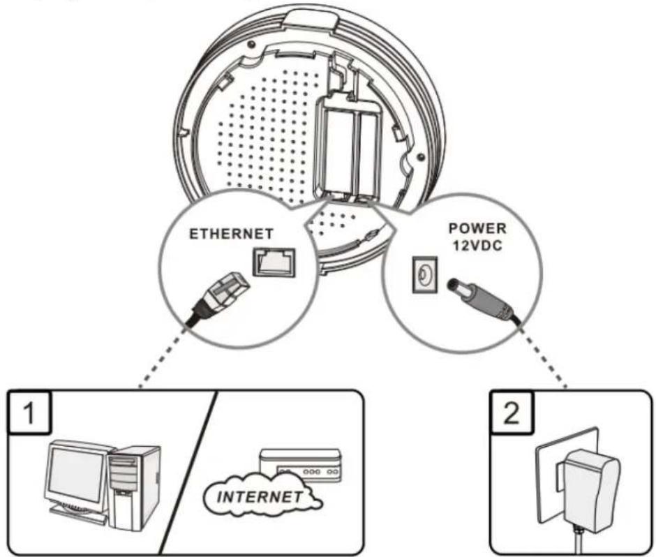
Hardware Preparation:
a. Connect an Ethernet cable between this device and the computer that you will operate to set up the device.
b. Power on the device via connecting the power adaptor DC Plug to the DC Jack of this device and plug in the power adaptor to an electrical outlet.
text_image
ETHERNET POWER 12VDC 1 INTERNET 2Software Preparation:
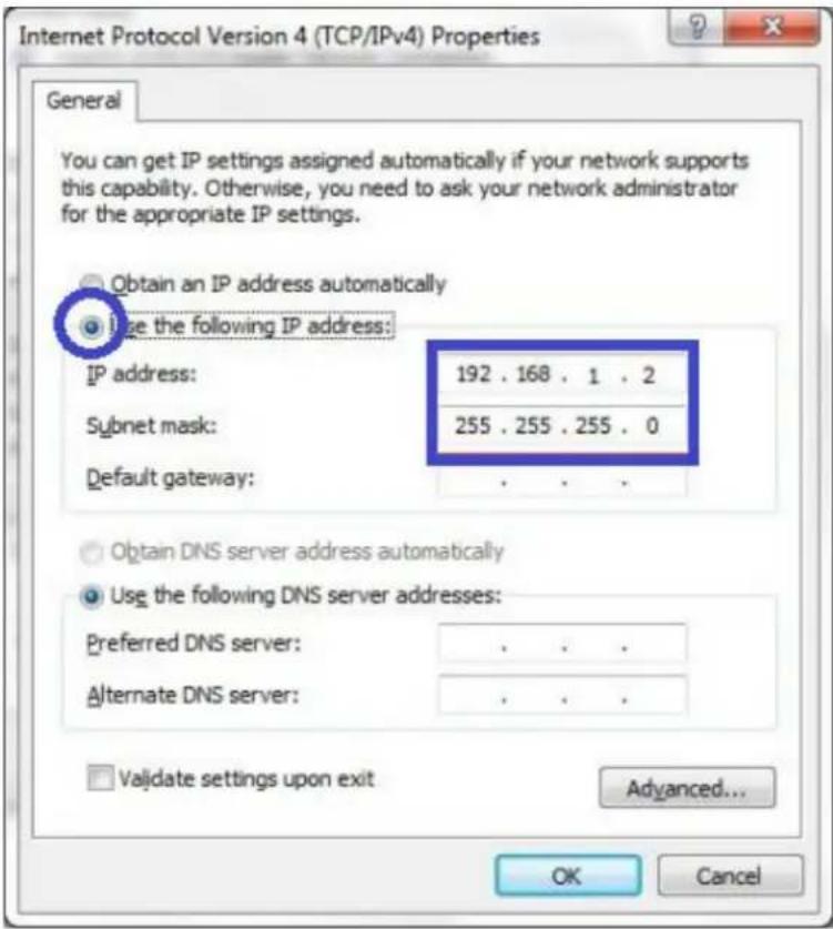
Most computers are connecting to a local network with dynamic IP (DHCP) setting. To access the web UI of the device, you have to change your computer's TCP/IPv4 settings into a static IP setting for the Ethernet Interface. You can refer to Appendix A for how to assign a Static IP address you your computer.
The device's default IP address is 192.168.1.1, and your computer must be assigned with a 192.168.1.x IP address to get access to the device.
Referring to Appendix A, and set the TCP/IPv4 address of your computer to 192.168.1.2, and subnet mask to 255.255.255.0.
text_image
Internet Protocol Version 4 (TCP/IPv4) Properties General You can get IP settings assigned automatically if your network supports this capability. Otherwise, you need to ask your network administrator for the appropriate IP settings. Obtain an IP address automatically Use the following IP address: IP address: 192 . 168 . 1 . 2 Subnet mask: 255 . 255 . 255 . 0 Default gateway: . Obtain DNS server address automatically Use the following DNS server addresses: Preferred DNS server: . Alternate DNS server: . Validate settings upon exit Advanced... OK CancelAfter applying this setting, you can now access to the web UI for configuring the device.
2.1 Easy Setup via Web UI
You can browse web UI to configure the device. Firstly you need to launch the Setup Wizard browser first and then the Setup Wizard will guide you step-by-step to finish the basic setup process.
Activate the setup wizard:
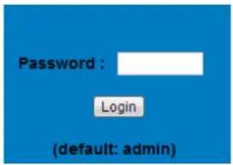
Type in the IP Address (http://192.168.1.1)

text_image
← → C 192.168.1.1Type the default password "admin" in the system authentication fields, and then click 'login' button.
text_image
Password : Login (default: admin)Select "Wizard" for basic settings in a simple way.
Or, you can go to Basic Network / Advanced Network / Applications / System to setup the configuration by your own selection.
text_image
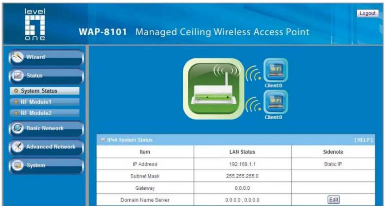
level one WAP-8101 Managed Ceiling Wireless Access Point Wizard Status System Status RF Module1 RF Module2 Basic Network Advanced Network System IPv4 System Status [HELP] Item LAN Status Sidenote IP Address 192.168.1.1 Static IP Subnet Mask 255.255.255.0 Gateway 0.0.0.0 Domain Name Server 0.0.0.0, 0.0.0.0 EditPress "Next" to start the Setup Wizard.

text_image
Setup Wizard will guide you through a basic configuration procedure step by step. ► Step 1. Setup Login Password. ► Step 2. LAN Setup ► Step 3. Wireless Setup. ► Step 4. Summary ► Step 5. Finish.Configure with the Setup Wizard
Step 1
You can change the password of administrator here.
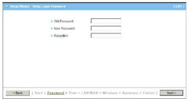
text_image
Setup Wizard - Setup Login Password [ EXIT ] • Old Password • New Password • Reconfirm < Back [ Start > Password > Time > LAN/WAN > Wireless > Summary > Finish? ] Next >Step 2
LAN IP Address.
You have to change the IP address of this device according to your network configuration.
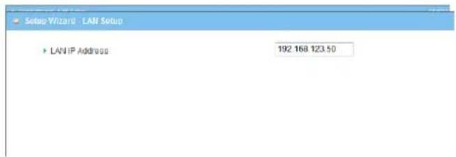
text_image
Setup Wizard - LAN Setup ▶ LAN IP Address 192.168.123.50Step 3-1
Wireless settings.
You can specify the Wireless setting for VAP1.
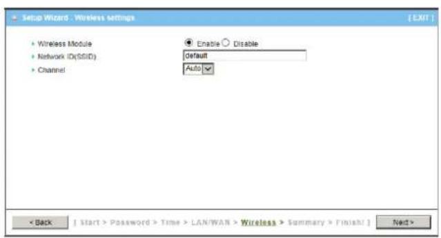
text_image
Setup Wizard - Wireless settings • Wireless Module • Network ID(SSID) • Channel Enable ○ Disable Default Auto < Back | Start > Password > Time > LAN/WAN > Wireless > Summary > Finish/ > Next >Step 3-2
Wireless settings.
Specify VAP1's wireless authentication and encryption.

text_image
Setup Wizard - Wireless settings • Wireless Module • Network ID(SSID) • Channel Enable ○ Disable Default Auto < Back [ Start > Password > Time > LAN/WAN > Wireless > Summary > Finish] Next >Step 4
Check the information again.
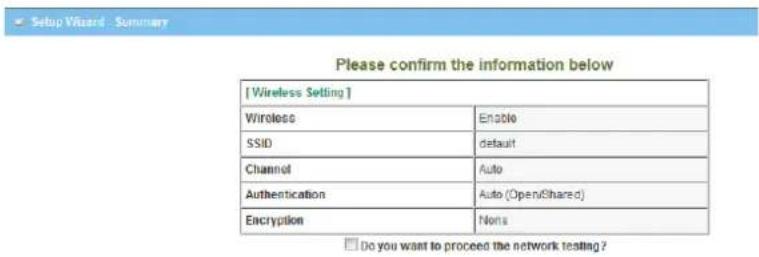
text_image
[Wireless Setting] Wireless Enable SSID Protein Channel Auto Authentication Auto (Open/Shared) Encryption None Do you want to proceed the network testing?Step 5
System is applying the setting.
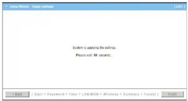
text_image
Setup Wizard - Apply settings System is applying the settings. Please wait 60 seconds... < Back [ Start > Password > Time > LAN/WAN > Wireless > Summary > Finish! ] Finish.Step 6
Click finish to complete it.

text_image
Setup Wizard - Apply settings [EXIT] Configuration is Completed. Please click 'Finish' to back to Status page. LAN IP Address is changed, please reconned manually. < Back [ Start > Password > Time > LAN/WAN > Wireless > Summary > Finish! ] Finish2.2 Use WEC Button to Setup Wireless Profiles
WEC (Wireless Easy Connection) is an easy configuration feature that is similar to well-known WPS function. It can be used to duplicate one device's wireless configuration to the other AP devices from the same manufacture by clicking one button for both devices.
There are two alternative AP modes defined for the device to operate with WEC (Wireless Easy Connection) feature. One is the Master Mode (by default), and the other is the Slave Mode. Before starting to use WEC to configure your AP devices, you have to learn how to identify and set the device in the Master Mode, or the Slave Mode (As stated in Section 1.2.4 and 1.2.5).
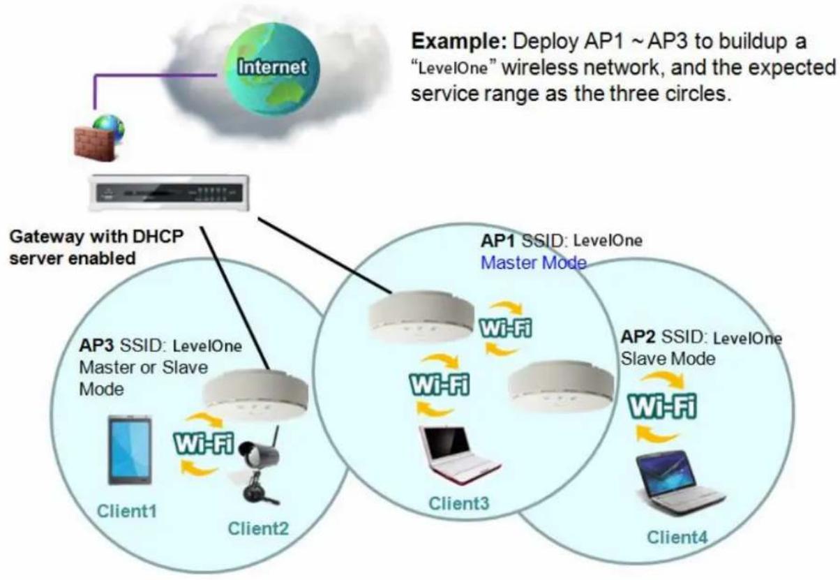
2.2.1 One Master and several isolated Slaves
flowchart
graph TD
    A["Internet"] --> B["AP3 SSID: LevelOne Master or Slave Mode"]
    B --> C["Client1"]
    B --> D["Client2"]
    B --> E["Wi-Fi"]
    F["AP1 SSID: LevelOne Master Mode"] --> G["Wi-Fi"]
    G --> H["Client3"]
    I["AP2 SSID: LevelOne Slave Mode"] --> J["Wi-Fi"]
    J --> K["Client4"]
    style A fill:#f9f,stroke:#333
    style F fill:#f9f,stroke:#333
    style I fill:#f9f,stroke:#333
As illustrated in above figure, how to configure the three APs (AP1, AP2, AP3) to build up the "staff" wireless network? You can follow the procedure bellow:
| Step | Button | Description |
| 1 | Set AP1 in Master Mode, and configure it via web UI. | 1. Make sure AP1 is in Master Mode (WiFi LED should be “Green” color, if not, you have to toggle its AP mode via pressing the WEC button for 9~10 seconds)2. Login in to AP1 web UI and configure the wireless settings as what you want (LAN IP, SSID, encryption key, etc..). |
| 2 | Set AP2 and AP3 in Slave Mode. | 1. Make sure AP2 / AP3 is in Slave Mode (WiFi LED should be “Amber” color, if not, you have to toggle its AP mode via pressing the WEC button for 9~10 seconds) |
| 3 | Easy configure AP2 via WEC. | Master to Slave WEC:1. Trigger AP1 into WEC configuration process via pressing the WEC button for 3 second.2. Trigger AP2 into WEC configuration process via pressing the WEC button for 3 second.3. It takes 30 ~ 60 seconds for the device to finish the WEC configuration process.(P.S:VAP1 of 2.4GHz or 5GHz in Salve Mode will get WiFi profile from Master AP1.) |
| 4 | Easy configure AP3 via WEC. | Master to Slave WEC:1. Trigger AP1 into WEC configuration process via pressing the WEC button for 3 second.2. Trigger AP3 into WEC configuration process via pressing the WEC button for 3 second.3. It takes 30 ~ 60 seconds for the device to finish the WEC configuration process.(P.S:VAP1 of 2.4GHz or 5GHz in Salve Mode will get WiFi profile from Master AP1.) |
| 5 | Mount the devices AP1, AP2, and AP3 to expected locations. | 1. Install AP1 to its location first and verify its wireless network connectivity with a client device (Client3).2. Install AP2 to its location and verify its wireless network connectivity with a client device (Client4) at the location beyond the service range of AP1.Besides, You can also check the AP2's WiFi LED, it should be “Solid Amber” if AP2 already connected a Master AP AP1.3. Install AP3 to its location and verify its wireless network connectivity with a client device (Client1) at the location beyond the service range of AP1.In this case, AP3 is located out of the service range of AP1, you don't have to check AP3' WiFi LED, but you have to connect the AP3 with an Ethernet cable to the gateway. |
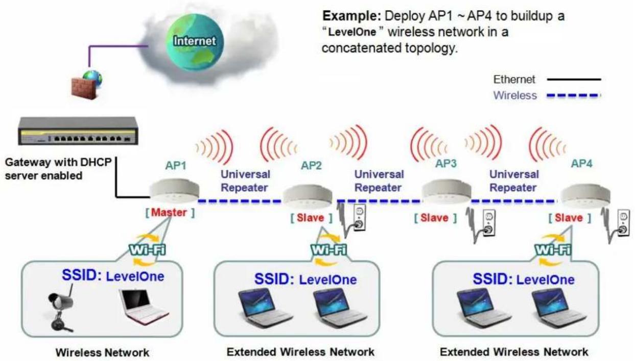
2.2.2 One Master and a series of connected Slaves
This device also supports universal repeater function, you can easily extend the wireless network with a series repeaters that are wireless concatenated to build up the wireless network without running Ethernet cables to each repeater.
flowchart
graph TD
    A["Internet"] --> B["Gateway with DHCP server enabled"]
    B --> C["AP1: Master"]
    C --> D["Universal Repeater"]
    D --> E["AP2: Slave"]
    E --> F["Universal Repeater"]
    F --> G["AP3: Slave"]
    G --> H["Universal Repeater"]
    H --> I["AP4: Slave"]
    I --> J["Extended Wireless Network"]

    subgraph Wireless Network
        K["Wi-Fi"] --> L["Master"]
        M["Wi-Fi"] --> N["Slave"]
    end

    subgraph Extended Wireless Network
        O["Wi-Fi"] --> P["Master"]
        Q["Wi-Fi"] --> R["Slave"]
    end

    style Wireless Network fill:#f9f,stroke:#333
    style Extended Wireless Network fill:#bbf,stroke:#333
As illustrated in above figure, if you intend to deploy 4 APs (AP1 \~ AP4) to create a "LevelOne" wireless network, you can follow the procedure below:
| Step | Button | Description |
| 1 | Set AP1 in Master Mode, and configure it via web UI. | 1. Make sure AP1 is in Master Mode (WiFi LED should be “Green” color, if not, you have to toggle its AP mode via pressing the WEC button for 8 seconds)2. Login in to AP1 web UI and configure the wireless settings as what you want (LAN IP, SSID, encryption key, etc..). |
| 2 | Set AP2, AP3, AP4 in Slave Mode. | 1. Make sure AP2 / AP3 / AP4 is in Slave Mode (WiFi LED should be “Amber” color, if not, you have to toggle its AP mode via pressing the WEC button for 8 seconds) |
| 3 | Easy configure AP2 via WEC. | Master to Slave WEC:1. Trigger AP1 into WEC configuration process via pressing the WEC button for 3 second.2. Trigger AP2 into WEC configuration process via pressing the WEC button for 3 second.3. It takes 30 ~ 60 seconds for the device to finish the WEC configuration process.(P.S:VAP1 of 2.4GHz or 5GHz in Salve Mode will get WiFi profile from Master AP1.) |
| 4 | Easy configure AP3 via WEC. | Slave to Slave WEC:1. Trigger AP2 into WEC configuration process via pressing the WEC button for 3 second.2. Trigger AP3 into WEC configuration process via pressing the WEC button for 3 second.3. It takes 30 ~ 60 seconds for the device to finish the WEC configuration process.(P.S:VAP1 of 2.4GHz or 5GHz in Salve Mode will get WiFi profile from Master AP1.) |
| 5 | Easy configure AP4 via WEC. | Slave to Slave WEC:1. Trigger AP3 into WEC configuration process via pressing the WEC button for 3 second.2. Trigger AP4 into WEC configuration process via pressing the WEC button for 3 second.3. It takes 30 ~ 60 seconds for the device to finish the WEC configuration process.(P.S:VAP1 of 2.4GHz or 5GHz in Salve Mode will get WiFi profile from Master AP1.) |
| 6 | Mount the devices AP1, AP2, AP3, and AP4 to expected locations. | 1. Install AP1 to its location first and verify its wireless network connectivity with a client device.2. Install AP2 to its location and verify its wireless network connectivity with a client device at the location beyond the service range of AP1. Besides, You can also check the AP2's WiFi LED, it should be "Solid Amber" if AP2 already connected a Master AP AP1.3. Install AP3 to its location and verify its wireless network connectivity with a client device at the location beyond the service range of AP2. Besides, You can also check the AP3's WiFiLED, it should be “Solid Amber” if AP3 already connected AP2.4. Install AP4 to its location and verify its wireless network connectivity with a client device at the location beyond the service range of AP3.Besides, You can also check the AP4’s WiFi LED, it should be “Solid Amber” if AP4 already connected AP3. |
Although such wireless repeater function is available, there are limitations for such topology.
First, the available bandwidth for AP2 \~ AP4 will be decayed due to it is connected to it peer AP wirelessly. It depends on the data rate and environment. Besides, if one of the AP, say AP2, is disconnected, the APs behind it will be disconnected as well. Such topology needs more maintenance effort to keep the whole wireless network connectivity.
If Ethernet cable is reachable, connecting each AP to an Ethernet Uplink is recommended.
Above WEC configuration process is also suitable for running Ethernet cables to AP2 \~ AP4 to get a better wireless network..
Chapter 3 Making Configurations
Whenever you want to configure your network or this device, you can access the Configuration Menu by opening the web-browser and typing in the IP Address of the device. The default IP Address is: 192.168.1.1. In the configuration section you may want to check the connection status of this device, to do Basic or Advanced Network setup or to check the system status. These task buttons can be easily found in the cover page of the UI (User Interface).

text_image
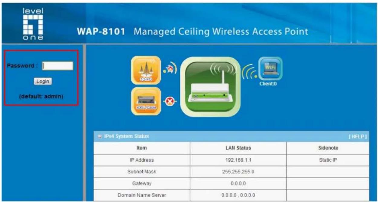
192.168.1.1Enter the default username and password "admin" in the System Password and then click 'login' button.
text_image
level one WAP-8101 Managed Ceiling Wireless Access Point Password : Login (default: admin) IPv4 System Status [HELP] Item LAN Status Sidenote IP Address 192.168.1.1 Static IP Subnet Mask 255.255.255.0 Gateway 0.0.0.0 Domain Name Server 0.0.0.0, 0.0.0.0Afterwards, you can go Wizard, Basic Network, Advanced Network, Application or System respectively on left hand side of web page.

text_image
level one WAP-8101 Managed Ceiling Wireless Access Point Wizard Status System Status RF Module1 Basic Network Advanced Network System IPv4 System Status [HELP] Item LAN Status Sidenote IP Address 192.168.1.1 Static IP Subnet Mask 255.255.255.0 Gateway 0.0.0.0 Domain Name Server 0.0.0.0, 0.0.0.0 EditNote: You can see the Connection Status screen below after you logged in.
| IPv4 System Status [HELP] | ||
| Item | LAN Status | Sidenote |
| IP Address | 192.168.1.1 | Static IP |
| Subnet Mask | 255.255.255.0 | |
| Gateway | 0.0.0.0 | |
| Domain Name Server | 0.0.0.0, 0.0.0.0 | Edit |
| Statistics Information | ||
| Transmit | Receive | |
| LAN | 76819 Packets | 8289 Packets |
| WLAN | 0 Packets | 0 Packets |
Note : You can see all the status of this device in the 'Status' main menu section.
3.1 Basic Network
You can enter Basic Network for Ethernet LAN, Wireless and IPv6 settings in this web page.

text_image
level one WAP-8101 Managed Ceiling Wireless Access Point Wizard Status Basic Network Ethernet LAN Wireless IPv6 Advanced Network System Basic Network Ethernet LAN Static IP : IP Address Subnet Mask Gateway DNS Server Address. DHCP Client : Allow a Network device to act as a host requesting configuration parameters, such as an IP address, from a DHCP server. Wireless Wireless : Allows Internet users to access your server(e.g. WWW, FTP) connected at LAN side. Advanced RF Module1 Settings : Allows Internet users to access your server(e.g. WWW, FTP) connected at LAN side. IPv6 IPv6 : In the Internet Protocol Version 6 (IPv6), the address block fe80::/10 has been reserved for link-local addressing.The actual link local addresses are assigned with the prefix fe80::/64.They may be assigned by automatic (stateless) or stateful (e.g. manual) mechanisms.3.1.1 Ethernet LAN
text_image
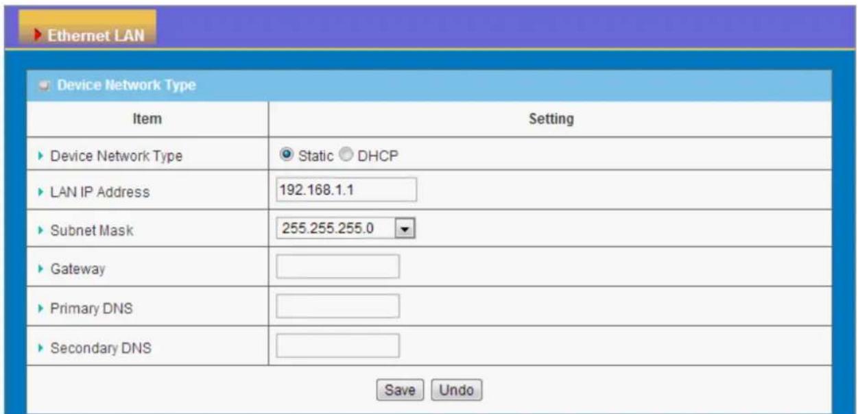
Ethernet LAN Device Network Type Item Setting ► Device Network Type Static DHCP ► LAN IP Address 192.168.1.1 ► Subnet Mask 255.255.255.0 ► Gateway ► Primary DNS ► Secondary DNS Save Undo- Device Network Type: This device supports two network types for connecting to your local network.
Static IP: Allow a device to act as a Static host. If you need Static host and please entry IP Address.
DHCP: Allow a device to act as a host requesting configuration parameters, such as an IP address from a DHCP server.
Note: Please check if there is DHCP server in your Network, first.
- LAN IP Address, Subnet Mask, Gateway, Primary / Secondary DNS: If you selected the Static IP network type for this device, you have to further specify the LAN IP Address, Subnet mask, Gateway, and optional Primary / Secondary DNS settings for well connecting to your local network.
3.1.2 Wireless
Wireless settings allow you to set the WLAN (wireless LAN) configuration items. When the wireless configuration is done, your wireless network is ready for supporting your local WiFi devices such as your laptop PC, wireless printer and some portable devices.
text_image
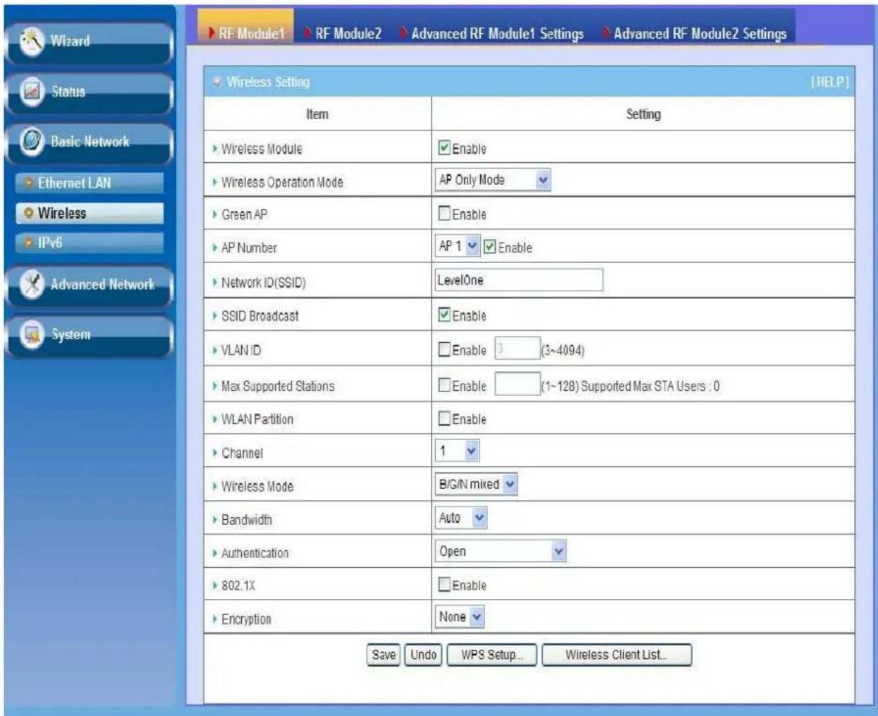
RF Module1 > RF Module2 > Advanced RF Module1 Settings > Advanced RF Module2 Settings Wizard Status Basic Network Ethernet LAN Wireless IPv6 Advanced Network System Wireless Setting [HELP] Item Setting ► Wireless Module Enable ► Wireless Operation Mode AP Only Mode ► Green AP Enable ► AP Number AP 1 Enable ► Network ID(SSID) LevelOne ► SSID Broadcast Enable ► VLAN ID Enable 3 (3~4094) ► Max Supported Stations Enable (1~128) Supported Max STA Users : 0 ► WLAN Partition Enable ► Channel 1 ► Wireless Mode B/G/N mixed ► Bandwidth Auto ► Authentication Open ► 802.1X Enable ► Encryption None Save Undo WPS Setup... Wireless Client List...The embedded RF Module1 is a IEEE 802.11b/g/n compliant 2.4GHz Wireless Module and RF Module2 is a IEEE 11g/n/ac compliant 5GHz Wireless Module.
3.1.2.1 Wireless Setup
There are several wireless operation modes provided by this device. They are: "AP Only Mode", "WDS Hybrid Mode", "WDS Only Mode", and "Universal Repeater Mode". You can choose the expected mode and configure the device manually.
Besides manually configuration the devices to be deployed one by one, you can also configure your devices via the simple WEC configuration approach as stated in last Chapter. By default, the Master AP is set to the WDS-hybrid Mode, and the Slave APs are set to the Universal Repeater mode. You just have to manually configure the Master AP via the web UI configuration, and use the WEC process for the rest Slave APs.
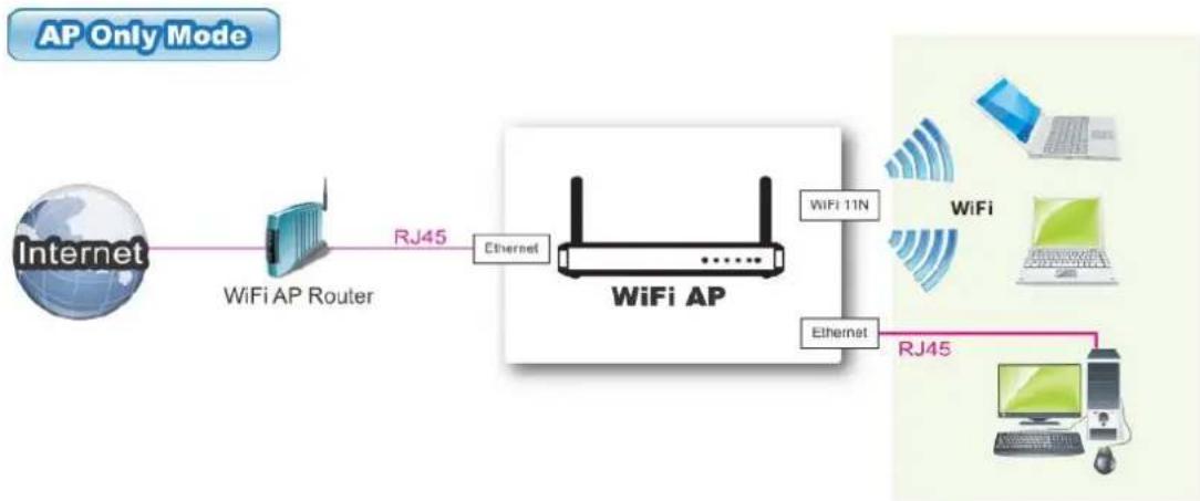
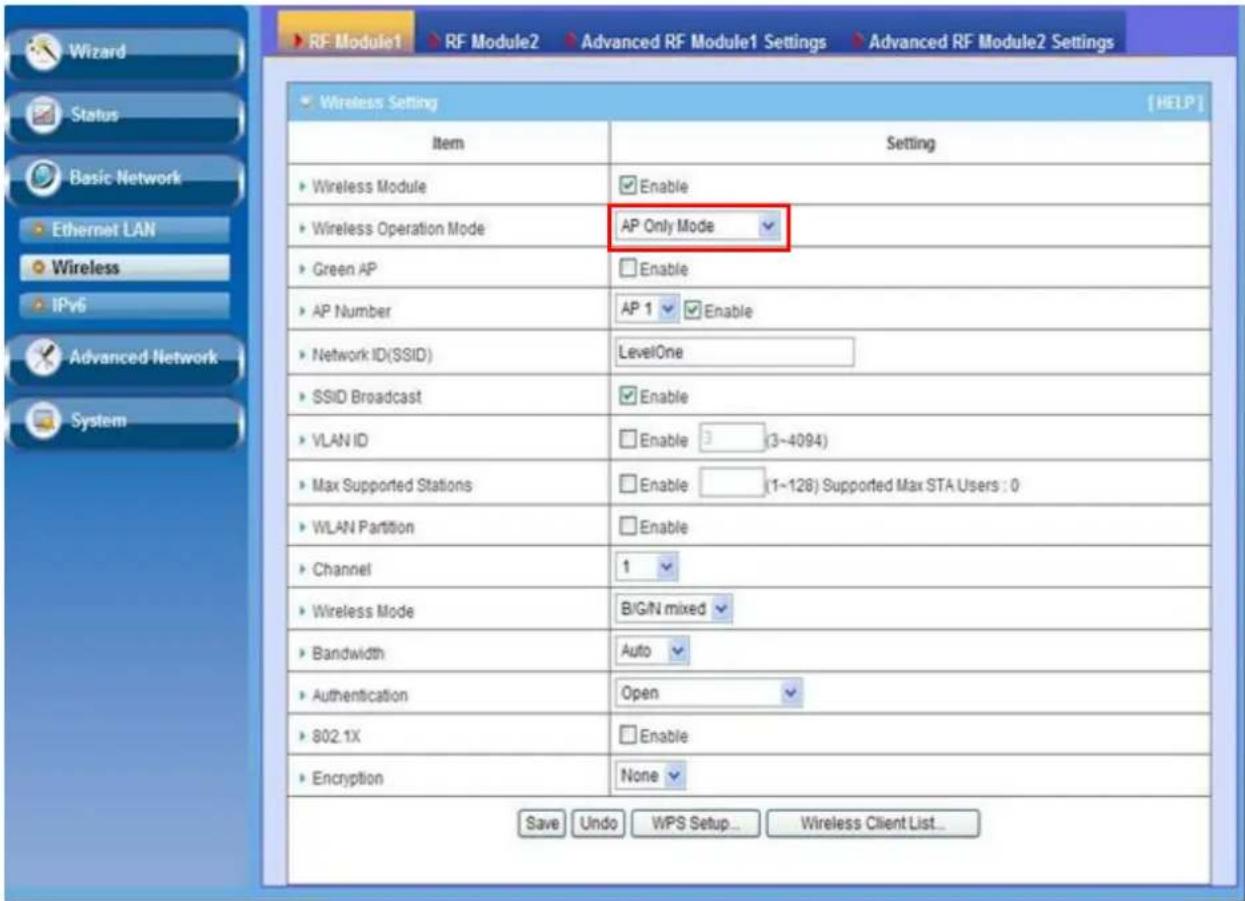
3.1.2.1.1 AP Only Mode
flowchart
graph LR
    A["Internet"] --> B["WiFi AP Router"]
    B --> C["WiFi AP"]
    C --> D["WiFi 11N"]
    C --> E["WiFi"]
    C --> F["Ethernet"]
    F --> G["Router"]
    G --> H["Wi-Fi"]
    G --> I["Wi-Fi"]
    G --> J["Wi-Fi"]
    G --> K["Wi-Fi"]
    G --> L["Wi-Fi"]
    G --> M["Wi-Fi"]
    G --> N["Wi-Fi"]
    G --> O["Wi-Fi"]
    G --> P["Wi-Fi"]
    G --> Q["Wi-Fi"]
    G --> R["Wi-Fi"]
    G --> S["Wi-Fi"]
    G --> T["Wi-Fi"]
    G --> U["Wi-Fi"]
    G --> V["Wi-Fi"]
    G --> W["Wi-Fi"]
    G --> X["Wi-Fi"]
    G --> Y["Wi-Fi"]
    G --> Z["Wi-Fi"]
    G --> AA["Wi-Fi"]
    G --> AB["Wi-Fi"]
    G --> AC["Wi-Fi"]
    G --> AD["Wi-Fi"]
    G --> AE["Wi-Fi"]
    G --> AF["Wi-Fi"]
    G --> AG["Wi-Fi"]
    G --> AH["Wi-Fi"]
    G --> AI["Wi-Fi"]
    G --> AJ["Wi-Fi"]
    G --> AK["Wi-Fi"]
    G --> AL["Wi-Fi"]
    G --> AM["Wi-Fi"]
    G --> AN["Wi-Fi"]
    G --> AO["Wi-Fi"]
    G --> AP["Wi-Fi"]
    G --> AQ["Wi-Fi"]
    G --> AR["Wi-Fi"]
    G --> AS["Wi-Fi"]
    G --> AT["Wi-Fi"]
    G --> AU["Wi-Fi"]
    G --> AV["Wi-Fi"]
    G --> AW["Wi-Fi"]
    G --> AX["Wi-Fi"]
    G --> AY["Wi-Fi"]
When acting as an access point, this device connects all the wireless stations to a wired network.
text_image
RF Module1 RF Module2 Advanced RF Module1 Settings Advanced RF Module2 Settings Wireless Setting [HELP] Item Setting Wireless Module Enable Wireless Operation Mode AP Only Mode Green AP Enable AP Number AP 1 Enable Network ID(SSID) LevelOne SSID Broadcast Enable VLAN ID Enable 3 (3~4094) Max Supported Stations Enable (1~128) Supported Max STA Users : 0 WLAN Partition Enable Channel 1 Wireless Mode BIG/N mixed Bandwidth Auto Authentication Open 802.1X Enable Encryption None Save Undo WPS Setup... Wireless Client List...- Wireless Module: Enable the wireless function.
- Wireless Operation Mode: Choose "AP Only Mode" from the list.
- Green AP: Enable the Green AP function to reduce the power consumption when there is no wireless traffic.
- AP Number: This device supports up to 8 SSIDs at the same time for you to manage your wireless networks. You can select AP1 \~ AP8 and configure each wireless network individually.
- Network ID (SSID): Network ID is used for identifying a Wireless LAN. Client stations can roam freely over this device and other Access Points that have the same Network ID. The factory default SSID is "default", you can change it to a meaningful identifier for the wireless users to easy find it out.
-
SSID Broadcast: By default, the SSID Broadcast setting is "Enable", and the device will broadcast beacons that have some information, including SSID, to the air, so that wireless clients can know how many AP devices by scanning the network. Therefore, if this setting is configured as "Disable", you can hide the wireless network from been scanned by wireless clients. Those who know the SSID can manually specify the SSID on their client device to connect the hidden wireless network.
-
VLAN ID: This device supports mapping of a SSID to a certain VLAN ID to
separate workgroups across wireless and wired domains. By default, it is not enables. If you enabled this function, you have to specify a VLAN ID for the wireless network.
- Max Supported Stations: You can specify the number of maximum stations that can associate to the SSID simultaneously.
- Channel: The radio channel number. The permissible channels depend on the Regulatory Domain. The factory default setting is auto channel selection. It's recommended to choose a channel that is not used in your environment to reduce radio interference
- Wireless Mode: The RF1 module supports 802.11b/g/n modes. You can also choose "N only", "G/N mixed" or "B/G/N mixed". The factory default setting is "B/G/N mixed".
- Bandwidth: The default setting for Bandwidth is "Auto". You can change it to "20MHz" with care if some clients are suffering from the connectivity problem in higher bandwidth setting.
- Authentication & Encryption: You may select one of the following authentications to secure your wireless network: Open (include 802.1x), Shared, Auto, WPA-PSK, WPA, WPA2-PSK, WPA2, WPA-PSK/WPA2-PSK, or WPA/WPA2.
- Open
Open system authentication simply consists of two communications. The first is an authentication request by the client that contains the station ID (typically the MAC address). This is followed by an authentication response from the AP containing a success or failure message. An example of when a failure may occur is if the client's MAC address is explicitly excluded in the AP's configuration.
In this mode you can also enable the 802.1x feature if you have another RADIUS server for user authentication. You need to input IP address, port, shared key of RADIUS server here.
| 802.1X | Enable |
| RADIUS Server IP | 0.0.0.0 |
| RADIUS port | 1812 |
| RADIUS Shared Key |
In this mode, you can only choose "None" or "WEP" in the encryption field.
- Shared
Shared key authentication relies on the fact that both stations taking part in the authentication process have the same "shared" key or passphrase. The
shared key is manually set on both the client station and the AP. Three types of shared key authentication are available today for home or small office WLAN environments.
- Auto
The gateway will select appropriate authentication method (Open or Shared) according to the WiFi client's request automatically.
- WPA-PSK
Select Encryption mode and enter the Pre-share Key. You can fill in 64 hexadecimal (0, 1, 2...8, 9, A, B...F) digits, or 8 to 63 ASCII characters as the pre-share key.
• WPA
Select Encryption mode and enter RADIUS Server related information. You have to specify the IP address, and port number for the RADIUS Server, and then fill in 64 hexadecimal (0, 1, 2...8, 9, A, B...F) digits, or 8 to 63 ASCII characters as the shared key. The key value is shared by the RADIUS server and this router. This key value must be consistent with the key value in the RADIUS server. The available encryption modes are “TKIP”, “AES”, or “TKIP/AES”.
- WPA2-PSK
Select Encryption mode and enter the Pre-share Key. You can fill in 64 hexadecimal (0, 1, 2...8, 9, A, B...F) digits, or 8 to 63 ASCII characters as the pre-share key.
WPA2
Select Encryption mode and enter RADIUS Server related information. You have to specify the IP address, and port number for the RADIUS Server, and then fill in 64 hexadecimal (0, 1, 2...8, 9, A, B...F) digits, or 8 to 63 ASCII characters as the shared key. The key value is shared by the RADIUS server and this router. This key value must be consistent with the key value in the RADIUS server. The available encryption modes are “TKIP”, “AES”, or “TKIP/AES”.
● WPA-PSK/WPA2-PSK
Select Encryption mode and enter the Pre-share Key. You can fill in 64 hexadecimal (0, 1, 2...8, 9, A, B...F) digits, or 8 to 63 ASCII characters as the pre-share key.
- WPA/WPA2
If some of wireless clients can only support WPA, but most of them can support WPA2. You can choose this option to support both of them. Select Encryption mode and enter RADIUS Server related information. You have to specify the IP address, and port number for the RADIUS Server, and then fill in 64 hexadecimal (0, 1, 2...8, 9, A, B...F) digits, or 8 to 63 ASCII characters as
the shared key. The key value is shared by the RADIUS server and this router. This key value must be consistent with the key value in the RADIUS server.
Afterwards, click on "Save" to store your settings or click "Undo" to give up the changes.
The 5GHz in configuration is the same as 2.4GHz configuration.
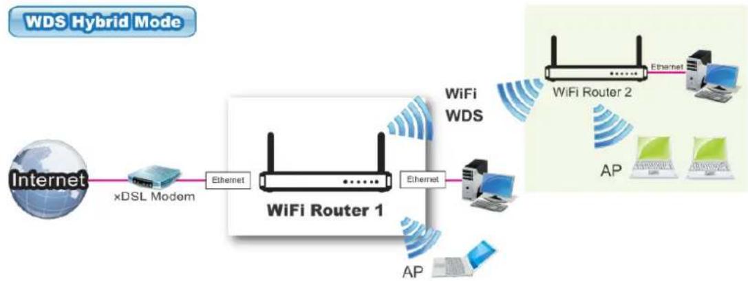
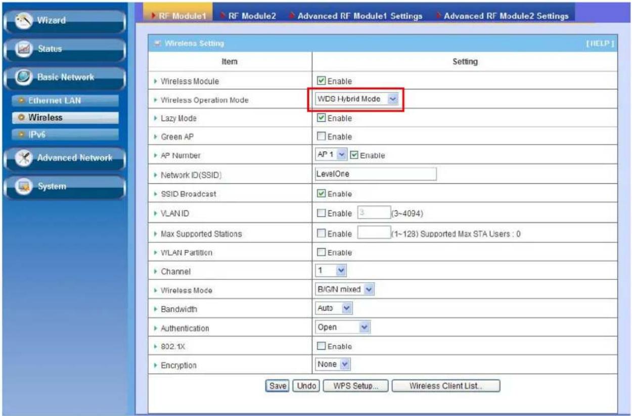
3.1.2.1.2 WDS Hybrid Mode
This mode makes device act as a wireless bridge but also have AP function. While acting as a wireless Bridge, Wireless Router 1 and Wireless Router 2 can communicate with each other through wireless interface (with WDS). Thus All Stations can communicate each other and are able to access Internet if Wireless Router 1 has the Internet connection.
flowchart
graph LR
    A["Internet"] --> B["xDSL Modem"]
    B --> C["Ethernet"]
    C --> D["WiFi Router 1"]
    D --> E["Ethernet"]
    E --> F["AP"]
    F --> G["WiFi Router 2"]
    G --> H["Ethernet"]
    H --> I["Wi-Fi WDS"]
    style A fill:#f9f,stroke:#333
    style B fill:#ccf,stroke:#333
    style C fill:#cfc,stroke:#333
    style D fill:#fcc,stroke:#333
    style E fill:#cff,stroke:#333
    style F fill:#ffc,stroke:#333
    style G fill:#fcf,stroke:#333
    style H fill:#cff,stroke:#333
    style I fill:#ffc,stroke:#333
text_image
RF Module1 > RF Module2 > Advanced RF Module1 Settings > Advanced RF Module2 Settings Wireless Setting Item Setting ► Wireless Module Enable ► Wireless Operation Mode WDS Hybrid Mode ► Lazy Mode Enable ► Green AP Enable ► AP Number AP 1 Enable ► Network ID(SSID) LevelOne ► SSID Broadcast Enable ► VLAN ID Enable 3 (3~4094) ► Max Supported Stations Enable (1~128) Supported Max STA Users : 0 ► WLAN Partition Enable ► Channel 1 ► Wireless Mode B/G/N mixed ► Bandwidth Auto ► Authentication Open ► 802.1X Enable ► Encryption None Save Undo WPS Setup... Wireless Client List...- Lazy Mode: This device support the Lazy Mode to automatically learn the MAC address of WDS peers, you don't have to input other peer AP's MAC address. However, not all the APs can be set to enable the Lazy mode simultaneously; at least there must be one AP with all the WDS peers' MAC address filled.
- Green AP: Enable the Green AP function to reduce the power consumption when there is no wireless traffic.
- AP Number: This device supports up to 8 SSIDs at the same time for you to manage your wireless networks. You can select AP1 \~ AP8 and configure each wireless network individually.
- Network ID (SSID): Network ID is used for identifying a Wireless LAN. Client stations can roam freely over this device and other Access Points that have the same Network ID. The factory default SSID is “default”, you can change it to a meaningful identifier for the wireless users to easy find it out.
- SSID Broadcast: By default, the SSID Broadcast setting is "Enable", and the device will broadcast beacons that have some information, including SSID, to the air, so that wireless clients can know how many AP devices by scanning the network. Therefore, if this setting is configured as "Disable", you can hide the wireless network from been scanned by wireless clients. Those who know the SSID can manually specify the SSID on their client device to connect the hidden wireless network.
- VLAN ID: This device supports mapping of a SSID to a certain VLAN ID to separate workgroups across wireless and wired domains. By default, it is not
enables. If you enabled this function, you have to specify a VLAN ID for the wireless network.
- Max Supported Stations: You can specify the number of maximum stations that can associate to the SSID simultaneously.
- Channel: The radio channel number. The permissible channels depend on the Regulatory Domain. The factory default setting is auto channel selection. It's recommended to choose a channel that is not used in your environment to reduce radio interference
- Wireless Mode: The RF1 module supports 802.11b/g/n modes. You can also choose "N only", "G/N mixed" or "B/G/N mixed". The factory default setting is "B/G/N mixed".
- Bandwidth: The default setting for Bandwidth is "Auto". You can change it to "20MHz" with care if some clients are suffering from the connectivity problem in higher bandwidth setting.
- Authentication & Encryption: You may select one of the following authentications to secure your wireless network: Open (include 802.1x), Shared, Auto, WPA-PSK, and WPA2-PSK.
- Open
Open system authentication simply consists of two communications. The first is an authentication request by the client that contains the station ID (typically the MAC address). This is followed by an authentication response from the AP containing a success or failure message. An example of when a failure may occur is if the client's MAC address is explicitly excluded in the AP's configuration.
In this mode you can also enable the 802.1x feature if you have another RADIUS server for user authentication. You need to input IP address, port, shared key of RADIUS server here.
| 802.1X | Enable |
| RADIUS Server IP | 0.0.0.0 |
| RADIUS port | 1812 |
| RADIUS Shared Key |
In this mode, you can only choose "None" or "WEP" in the encryption field.
- Shared
Shared key authentication relies on the fact that both stations taking part in the authentication process have the same "shared" key or passphrase. The shared key is manually set on both the client station and the AP. Three types of shared key authentication are available today for home or small office WLAN environments.
- Auto
The gateway will select appropriate authentication method (Open or Shared) according to the WiFi client's request automatically.
- WPA-PSK
Select Encryption mode and enter the Pre-share Key. You can fill in 64 hexadecimal (0, 1, 2...8, 9, A, B...F) digits, or 8 to 63 ASCII characters as the pre-share key.
- WPA2-PSK
Select Encryption mode and enter the Pre-share Key. You can fill in 64 hexadecimal (0, 1, 2...8, 9, A, B...F) digits, or 8 to 63 ASCII characters as the pre-share key.
- Remote AP MAC 1 \~ Remote AP MAC 4: If you do not enable the Lazy mode, you have to enter the wireless MAC address for each WDS peer one by one.
Afterwards, click on "Save" to store your settings or click "Undo" to give up the changes.
The 5GHz in configuration is the same as 2.4GHz configuration.
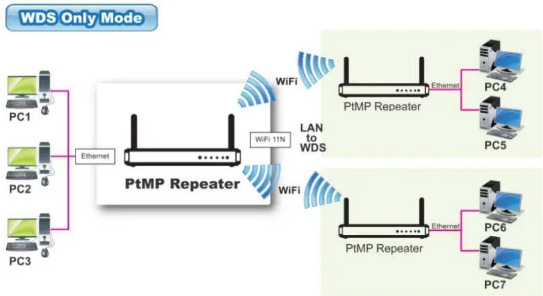
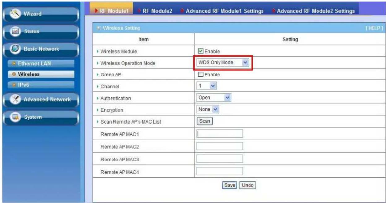
3.1.2.1.3 WDS Only Mode
WDS (Wireless Distributed System) function let APs acts as a wireless LAN bridge. All stations associated with WDS APs could see each other and roam through APs without changing WiFi configurations. You can use this feature to build up a large wireless network in a large space like airports, hotels and schools ...etc.
flowchart
graph TD
    PC1["PC1"] -->|Ethernet| PtMP_Repeater["PtMP Repeater"]
    PC2["PC2"] -->|Ethernet| PtMP_Repeater
    PC3["PC3"] -->|Ethernet| PtMP_Repeater
    PtMP_Repeater -->|WiFi 11N| WiFi1["WiFi"]
    WiFi1 -->|WiFi| PtMP_Repeater
    PtMP_Repeater -->|LAN to WDS| PtMP_Repeater
    PtMP_Repeater -->|Ethernet| PC4["PC4"]
    PtMP_Repeater -->|Ethernet| PC5["PC5"]
    PtMP_Repeater -->|Ethernet| PC6["PC6"]
    PtMP_Repeater -->|Ethernet| PC7["PC7"]
text_image
RF Module1 > RF Module2 > Advanced RF Module1 Settings > Advanced RF Module2 Settings Wireless Setting [HELP] Item Setting ► Wireless Module Enable ► Wireless Operation Mode WDS Only Mode ► Green AP Enable ► Channel 1 ► Authentication Open ► Encryption None ► Scan Remote AP's MAC List Scan Remote AP MAC1 Remote AP MAC2 Remote AP MAC3 Remote AP MAC4 Save Undo- Lazy Mode: This device support the Lazy Mode to automatically learn the MAC address of WDS peers, you don't have to input other peer AP's MAC address. However, not all the APs can be set to enable the Lazy mode simultaneously; at least there must be one AP with all the WDS peers' MAC address filled.
- Green AP: Enable the Green AP function to reduce the power consumption when there is no wireless traffic.
- Channel: The radio channel number. The permissible channels depend on the Regulatory Domain. The factory default setting is auto channel selection. It's recommended to choose a channel that is not used in your environment to reduce radio interference
- Wireless Mode: The RF1 module supports 802.11b/g/n modes. You can also choose "N only", "G/N mixed" or "B/G/N mixed". The factory default setting is "B/G/N mixed".
- Bandwidth: The default setting for Bandwidth is "Auto". You can change it to "20MHz" with care if some clients are suffering from the connectivity problem in higher bandwidth setting.
- Authentication & Encryption: You may select one of the following authentications to secure your wireless network: Open (include 802.1x), Shared, Auto, WPA-PSK, and WPA2-PSK.
- Open
Open system authentication simply consists of two communications. The first is an authentication request by the client that contains the station ID (typically the MAC address). This is followed by an authentication response from the AP containing a success or failure message. An example of when a failure may occur is if the client's MAC address is explicitly excluded in the AP's configuration.
In this mode you can also enable the 802.1x feature if you have another RADIUS server for user authentication. You need to input IP address, port, shared key of RADIUS server here.
| 802.1X | Enable |
| RADIUS Server IP | 0.0.0.0 |
| RADIUS port | 1812 |
| RADIUS Shared Key |
In this mode, you can only choose "None" or "WEP" in the encryption field.
- Shared
Shared key authentication relies on the fact that both stations taking part in the authentication process have the same "shared" key or passphrase. The shared key is manually set on both the client station and the AP. Three types of shared key authentication are available today for home or small office WLAN environments.
- Auto
The gateway will select appropriate authentication method (Open or Shared) according to the WiFi client's request automatically.
- WPA-PSK
Select Encryption mode and enter the Pre-share Key. You can fill in 64 hexadecimal (0, 1, 2...8, 9, A, B...F) digits, or 8 to 63 ASCII characters as the pre-share key.
- WPA2-PSK
Select Encryption mode and enter the Pre-share Key. You can fill in 64 hexadecimal (0, 1, 2...8, 9, A, B...F) digits, or 8 to 63 ASCII characters as the pre-share key.
- Remote AP MAC 1 \~ Remote AP MAC 4: If you do not enable the Lazy mode, you have to enter the wireless MAC address for each WDS peer one by one.
Afterwards, click on "Save" to store your settings or click "Undo" to give up the changes.
The 5GHz in configuration is the same as 2.4GHz configuration.
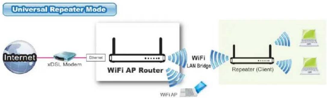
3.1.2.1.4 Universal Repeater Mode
Universal Repeater is a technology used to extend wireless coverage. It provides the function to act as Adapter (Client) and AP at the same time and can use this function to connect to a Root AP and use AP (SSID name must be the same as that of Root AP) function to service all wireless stations within its coverage. All the stations within the coverage of this access point can be bridged to the Root AP.
flowchart
graph LR
    A["Internet"] --> B["xDSL Modem"]
    B --> C["Ethernet"]
    C --> D["WiFi AP Router"]
    D --> E["WiFi LAN Bridge"]
    E --> F["Repeater (Client)"]
    F --> G["Computer"]
    D --> H["WiFi AP"]
    H --> I["Client"]

text_image
RF Module1 > RF Module2 > Advanced RF Module1 Settings > Advanced RF Module2 Settings Wizard Status Basic Network Ethernet LAN Wireless IPv6 Advanced Network System Wireless Setting Item Setting ► Wireless Module Enable ► Wireless Operation Mode Universal Repeater ► Green AP Enable ► AP Number AP 1 Enable ► Network ID(SSID) LevelOne ► Destination AP MAC ► Destination AP MAC2 Enable ► WEC Config Status UNCONFIGURED Release ► SSID Broadcast Enable ► VLAN ID Enable 3 (3~4094) ► Channel 1 ► Bandwidth Auto ► Authentication Open ► Encryption None Save Undo WPS Setup... Wireless Client List... Scan- Green AP: Enable the Green AP function to reduce the power consumption when there is no wireless traffic.
- Network ID (SSID): Network ID is used for identifying a Wireless LAN. Client stations can roam freely over this device and other Access Points that have the same Network ID. The factory default SSID is “default”, you have to change it to the same SSID of the peer AP to be associated under the Universal Repeater Mode.
- Destination AP MAC: Besides to have the same SSID of the peer AP to be associated under the Universal Repeater mode, you also have to specify the MAC address of the peer AP to avoid making wrong connection with other AP that has the same SSID.
- SSID Broadcast: By default, the SSID Broadcast setting is "Enable", and the device will broadcast beacons that have some information, including SSID, to the air, so that wireless clients can know how many AP devices by scanning the
network. Therefore, if this setting is configured as “Disable”, you can hide the wireless network from been scanned by wireless clients. Those who know the SSID can manually specify the SSID on their client device to connect the hidden wireless network.
- VLAN ID: This device supports mapping of a SSID to a certain VLAN ID to separate the workgroups across wireless and wired domains. By default, it is not enables. If you enabled this function, you have to specify a VLAN ID for the wireless network.
- Max Supported Stations: You can specify the number of maximum stations that can associate to the SSID simultaneously.
- Channel: The radio channel number. The permissible channels depend on the Regulatory Domain. The factory default setting is auto channel selection. It's recommended to choose a channel that is not used in your environment to reduce radio interference
- Bandwidth: The default setting for Bandwidth is "Auto". You can change it to "20MHz" with care if some clients are suffering from the connectivity problem in higher bandwidth setting.
- Authentication & Encryption: You may select one of the following authentications to secure your wireless network: Open, Shared, Auto, WPA-PSK, and WPA2-PSK.
Afterwards, click on "Save" to store your settings or click "Undo" to give up the changes.
The 5GHz in configuration is the same as 2.4GHz configuration.
3.1.2.2 Advanced Wireless Setup
This device provides advanced wireless setup for professional user to optimize the wireless performance under the specific installation environment.
3.1.2.2.1 Advanced RF Module1 Settings

text_image
Wizard Status Basic Network Ethernet LAN Wireless IPv6 Advanced Network System RF Module1 > RF Module2 > Advanced RF Module1 Settings > Advanced RF Module2 Settings Advanced RF Module1 Settings [HELP] Item Setting Regulatory Domain ● FCC(United States) ○ ETSI(Europe) Please make sure the regulatory domain you choose is legal to use in your country. Using the wrong regulatory domain is not allowed. Beacon Interval 100(msec, range:1~1000) Transmit Power 100% RTS Threshold 2347(1~2347) Fragmentation 2346(256~2346) DTIM Interval 3range (1~255) WMM Capable ✓ Enable AP Isolation Off TX Rates Besi Save Undo- Regulatory Domain: The availability of some specific channels and/or operational frequency bands is country dependent.
- Beacon interval: Beacons are packets sent by a wireless router to synchronize wireless devices.
- Transmit Power: Normally the wireless transmission power operates at 100% out power specification of this device. You can lower down the power ratio to prevent transmissions from reaching beyond your corporate/home office or designated wireless area.
- RTS Threshold: If an excessive number of wireless packet collision occurred, the wireless performance will be affected. It can be improved by adjusting the RTS/CTS (Request to Send/Clear to Send) threshold value.
- Fragmentation: Wireless frames can be divided into smaller units (fragments) to improve performance in the presence of RF interference and at the limits of RF coverage.
- DTIM interval: A DTIM is a countdown informing clients of the next window for listening to broadcast and multicast messages. When the wireless router has buffered broadcast or multicast messages for associated clients, it sends the next DTIM with a DTIM Interval value.
- WMM Capable: WMM can help control latency and jitter when transmitting multimedia content over a wireless connection.
- WLAN Partition: You can check the WLAN Partition function to separate the wireless clients associated to the same VAP. The wireless clients can't
communicate each other, but they can access the internet and other Ethernet LAN devices
- AP Isolation: If you enabled multiple VAPs in this device, you can further decide whether the wireless clients associated to different VAPs can access to each other or not. When you enabled the AP Isolation function, Each VAP is isolated to the others consequently.
- TX Rate: For WiFi transmit rate, you can choose "Best" for auto-adjustment according to WiFi signal quality in your environment, or you can fix it in certain TX rate. Please note the WiFi connection may be dropped if you fix at a higher date rate but in a noisy (poor RF signal quality) environment.
Afterwards, click on "Save" to store your settings or click "Undo" to give up the changes.
3.1.2.2.2 Advanced RF Module2 Settings

text_image
Wizard Status Basic Network Ethernet LAN Wireless IPv6 Advanced Network System RF Module1 RF Module2 Advanced RF Module1 Settings Advanced RF Module2 Settings Advanced RF Module2 Settings [HELP] Item Setting Regulatory Domain US EU Please make sure the regulatory domain you choose is legal to use in your country. Using the wrong regulatory domain is not allowed. Beacon Interval 100 Range (1~1000 msec) Transmit Power 100% RTS Threshold 2347 (1~2347) Fragmentation 2346 (256~2346) DTIM Interval 3 range (1~255) WMM Capable Enable AP Isolation Off TX Rates Best Save Undo- Regulatory Domain: The availability of some specific channels and/or operational frequency bands is country dependent.
- Beacon interval: Beacons are packets sent by a wireless router to synchronize wireless devices.
- Transmit Power: Normally the wireless transmission power operates at 100% out power specification of this device. You can lower down the power ratio to prevent transmissions from reaching beyond your corporate/home office or designated wireless area.
-
RTS Threshold: If an excessive number of wireless packet collision occurred, the wireless performance will be affected. It can be improved by adjusting the RTS/CTS (Request to Send/Clear to Send) threshold value.
-
Fragmentation: Wireless frames can be divided into smaller units (fragments) to improve performance in the presence of RF interference and at the limits of RF coverage.
- DTIM interval: A DTIM is a countdown informing clients of the next window for listening to broadcast and multicast messages. When the wireless router has buffered broadcast or multicast messages for associated clients, it sends the next DTIM with a DTIM Interval value.
- WMM Capable: WMM can help control latency and jitter when transmitting multimedia content over a wireless connection.
- AP Isolation: If you enabled multiple VAPs in this device, you can further decide whether the wireless clients associated to different VAPs can access to each other or not. When you enabled the AP Isolation function, Each VAP is isolated to the others consequently.
- TX Rate: For WiFi transmit rate, you can choose "Best" for auto-adjustment according to WiFi signal quality in your environment, or you can fix it in certain TX rate. Please note the WiFi connection may be dropped if you fix at a higher date rate but in a noisy (poor RF signal quality) environment.
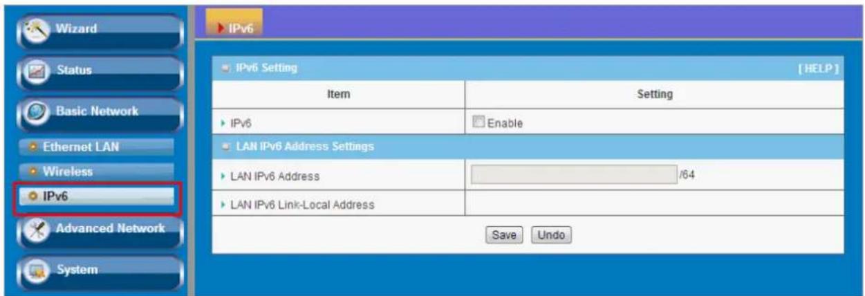
3.1.3 IPv6
The growth of the Internet has created a need for more addresses than are possible with IPv4. IPv6 (Internet Protocol version 6) is a version of the Internet Protocol (IP) intended to succeed IPv4, which is the protocol currently used to direct almost all Internet traffic. IPv6 also implements additional features not present in IPv4. It simplifies aspects of address assignment (stateless address auto-configuration), network renumbering and router announcements when changing Internet connectivity providers.
This device supports IPv6, it works as a IPv6 bridge, you can use it to build a IPv6 network.
text_image
Wizard Status Basic Network Ethernet LAN Wireless IPv6 Advanced Network System IPv6 Setting [ HELP ] Item Setting IPv6 Enable LAN IPv6 Address Settings LAN IPv6 Address /64 LAN IPv6 Link-Local Address Save Undo- LAN IPv6 address settings: Please enter "LAN IPv6 address" and ignore the "LAN IPv6 Link-Local address".
"2001:0db8:85a3:0000:0000:8a2e:0370:7334"
3.2 Advanced Network
This device also supports other advanced network features for you to further manage the device. You can finish the configuration for Firewall, and Management in this section.

text_image
Wizard Status Basic Network Advanced Network Firewall Management System Advanced Network • Firewall - MAC Address Control : MAC Address Control allows you to assign different access rule for different users. • Management - UPnP : If you enable UPnP function, the router will work with UPnP devices/software. - SNMP : Allow you to use SNMP utility to manage this device.3.2.1 Firewall
3.2.1.1 MAC Address Control
MAC Address Control allows you to assign different access right for different users and to assign a specific IP address to a certain MAC address.
| MAC Address Control [HELP] | ||
| Item | Setting | |
| MAC Address Control | Enable | |
| Association control | Wireless clients with A checked can associate to the wireless LAN; and allow unspecified MAC addresses to associate. | |
| ID | MAC | A |
| 1 | ☐ | |
| 2 | ☐ | |
| 3 | ☐ | |
| 4 | ☐ | |
| 5 | ☐ | |
| <<Previous Next>> Save Undo | ||
-
MAC Address Control: Check "Enable" to enable the "MAC Address Control". All of the settings in this page will take effect only when "Enable" is checked.
-
Association control: Check "Association control" to enable the control of which wireless client can associate to the wireless LAN. If a client is denied to associate to the wireless LAN, it means the client can't send or receive any data via this device. Choose "allow" or "deny" to allow or deny the clients, whose MAC addresses are not in the "Control table", to associate to the wireless LAN.
Afterwards, click on "Save" to store your settings or click "Undo" to give up the changes.
3.2.2 Management
3.2.2.1 UPNP
UPnP Internet Gateway Device (IGD) Standardized Device Control Protocol is a NAT port mapping protocol and is supported by some Network device. It is a common communication protocol of automatically configuring port forwarding. Applications using peer-to-peer networks, multiplayer gaming, and remote assistance programs need a way to communicate through home and business gateways. Without IGD one has to manually configure the gateway to allow traffic through, a process which is error prone and time consuming

text_image
UPnP SNMP UPnP setting [ HELP ] Item Setting UPnP setting Enable Save Undo Firewall Management SystemThis device supports the UPnP Internet Gateway Device (IGD) feature. By default, it is enabled.
3.2.2.2 SNMP
In brief, SNMP, the Simple Network Management Protocol, is a protocol designed to give a user the capability to remotely manage a computer network by polling and setting terminal values and monitoring network events.
| SNMP Setting [HELP] | |
| Item | Setting |
| Enable SNMP | Local |
| SNMP Version | v1 v2c v3 |
| Get Community | |
| Set Community | private |
| SNMP Setting | |
| User 1 | Enable |
| SNMPv3 Settings: User 1 | Read Read/Write |
| User 1 AUTH Mode | MD5 SHA |
| User 1 Privacy Mode | noAuthNoPriv authNoPriv authPriv |
| Username 1 | |
| Password 1(len>=8) | |
| User 1 Priv Key | |
| SNMP Setting | |
| User 2 | Enable |
| SNMPv3 Settings: User 2 | Read Read/Write |
| User 2 AUTH Mode | MD5 SHA |
| User 2 Privacy Mode | noAuthNoPriv authNoPriv authPriv |
| Username 2 | |
| Password 2(len>=8) | |
| User 2 Priv Key | |
| IP | |
| IP 1 | |
| IP 2 | |
| IP 3 | |
| IP 4 | |
| Save Undo | |
- Enable SNMP: Enable this Function.
- SNMP Version: Supports SNMP V1, V2c, and V3.
- Get Community: The community of GetRequest that this device will respond. This is a text password mechanism that is used to weakly authenticate queries to agents of managed network devices.
- Set Community: The community of SetRequest that this device will accept.
- SNMPv3 Settings: User 1/2: This device supports up to two SNMP management
accounts. You can specify the account permission as "Read" or "Read/Write" respectively.
- User 1/2 AUTH Mode: Select MD5 or SHA as the method of password encryption for the specified level of access, or to disable authentication.
- User 1/2 Privacy Mode: You can configure the SNMP privacy mode. There are three modes for you to choose: "noAuthNoPriv" for both authentication and private key are not required, "authNoPriv" for no private key required, and "authPriv" for both authentication and private key required.
- Username 1/2: Use this field to identify the user name for the specified level of access.
- Password 1/2: Use this field to set the password for the specified level of access.
- User 1/2 Priv Key: Use this field to define the encryption key for the specified level of access.
- IP (Trap Event Receiver) 1 \~ 4: Enter the IP addresses or Domain Name of your SNMP Management PCs. You have to specify the IP address, so that the device can send SNMP Trap message to the management PCs consequently.
Afterwards, click on “Save” to store your settings or click “Undo” to give up the changes.
3.3 System
In this section you can see system information, system logs, use system tools for system update and do service scheduling and system administration setting.

text_image
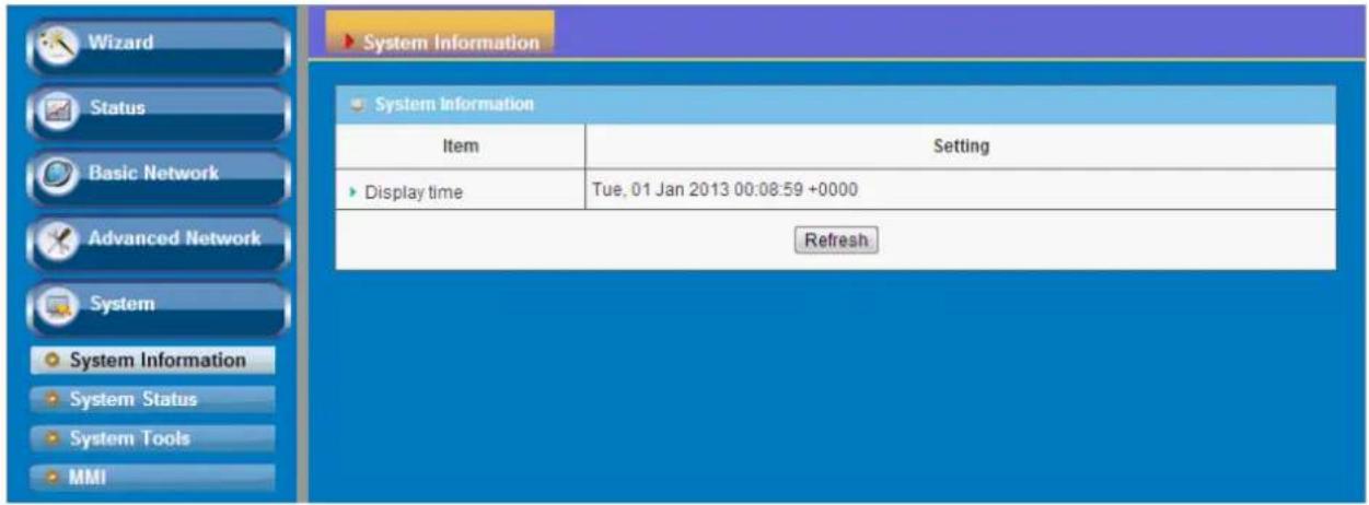
Wizard Status Basic Network Advanced Network System System Information System Status System Tools MMI System System Information - View System information. System Status - View system logs. System Tools - Change Password : Allow you to change system password. This password is used for web GUI login. - FW Upgrade : Upgrade new firmware or restore backup settings. - System Time : Allow you to set device time manually or consult network time from NTP server. - Others - Backup Setting : Backup current device settings. - Reset to Default : Reset the settings of this device to the default values. - Reboot : Restart this device. MMI - Administrator Time-out: The amount of time of inactivity before the device will automatically close the Administrator session. Set this to zero to disable it.3.3.1 System Information
You can view the System Information in this page.
text_image
Wizard Status Basic Network Advanced Network System System Information System Status System Tools MMI System Information Item Setting Display time Tue, 01 Jan 2013 00:08:59 +0000 Refresh3.3.2 System Status
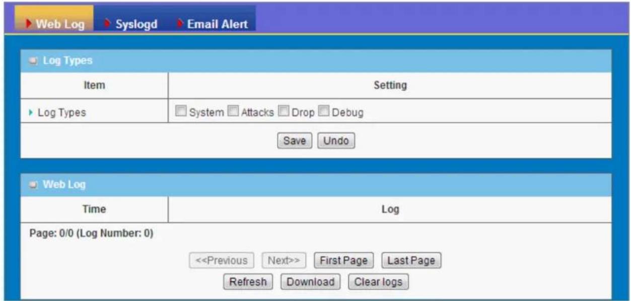
3.3.2.1 Web Log
text_image
Web Log Syslogd Email Alert Log Types Item Setting Log Types System Attacks Drop Debug Save Undo Web Log Time Log Page: 0/0 (Log Number: 0) <-
Log Types: You can select the log types to be collected in the web log area. There are "System", "Attacks", "Drop", and "Debug" types for you to select.
-
Web Log: You can browse, refresh, download, and clear the log messages.
3.3.2.2 Syslog
This device also can export system logs to specific destination by means of syslog (UDP) and SMTP(TCP). With enabled Syslog function, this device will send log to a certain host periodically. You need to install a syslog utility on a host to receive syslogs

text_image
Web Log Syslogd Email Alert System Log [ HELP ] Item Setting Enable IP address for syslogd Save UndoThe items you have to setup include:
- IP Address for syslogd: Host IP of destination where syslog will be sent to. Check Enable to enable this function.
3.3.2.3 Email Alert

text_image
Web Log Syslogd Email Alert Email Alert [HELP] Item Setting Enable Setting of Email alert SMTP Server : port admin SMTP Username SMTP Password ...... E-mail addresses E-mail subject Save Undo View Log... Email Log NowThis device can also export system logs via sending emails to specific recipients. The items you have to setup include:
- Setting of Email alert: Check if you want to enable Email alert (send syslog via email).
- SMTP Server: Port: Input the SMTP server IP and port, which are connected with '': If you do not specify port number, the default value is 25. For example, "mail.your_url.com" or "192.168.1.100:26".
- SMTP Username: Enter the Username offered by your ISP.
- SMTP Password: Enter the password offered by your ISP.
- E-mail Addresses: The recipients are the ones who will receive these logs. You can assign more than 1 recipient, using ';' or ',' to separate these email addresses.
- E-mail Subject: The subject of email alert is optional.
Afterwards, click on "Save" to store your settings or click "Undo" to give up the changes.
3.3.3 System Tools
3.3.3.1 Change Password
You can change the System Password here. We strongly recommend you to change the system password for security reason. Click on "Save" to store your settings or click "Undo" to give up the changes.
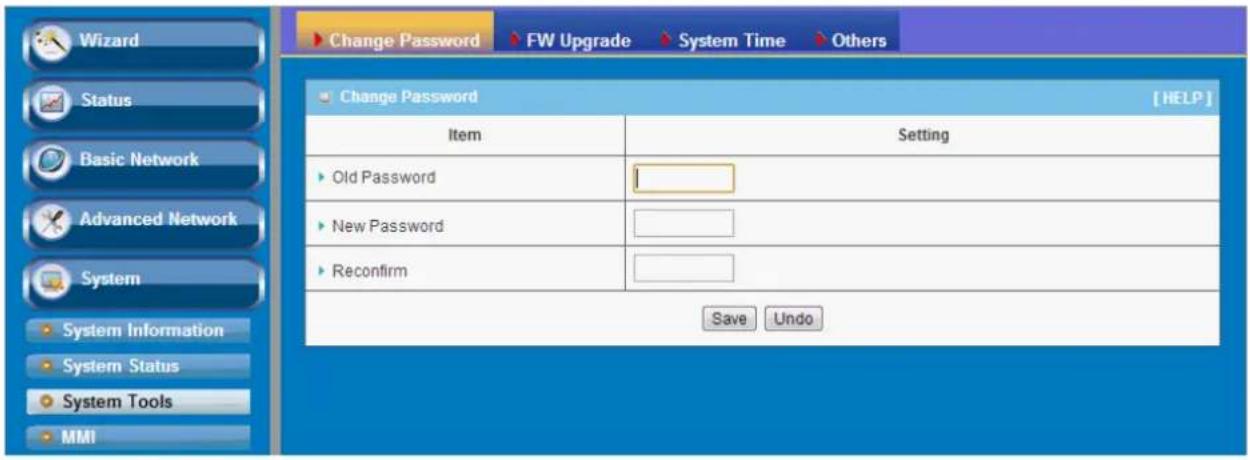
text_image
Change Password FW Upgrade System Time Others Change Password [ HELP ] Item Setting ► Old Password ► New Password ► Reconfirm Save Undo3.3.3.2 FW Upgrade
If new firmware is available, you can upgrade device firmware through the WEB GUI here.
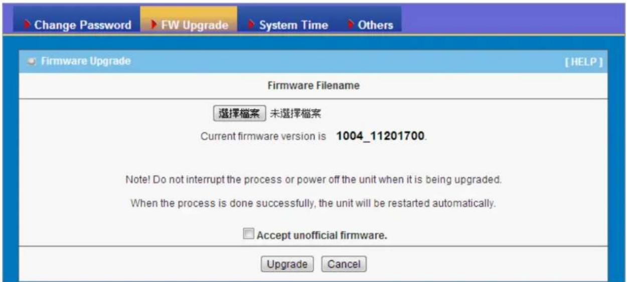
text_image
Change Password FW Upgrade System Time Others Firmware Upgrade [FHLP] Firmware Filename 選擇檔案 未選擇檔案 Current firmware version is 1004_11201700. Note! Do not interrupt the process or power off the unit when it is being upgraded. When the process is done successfully, the unit will be restarted automatically. □ Accept unofficial firmware. Upgrade CancelPress "browse" button to indicate the file name of new firmware, and then press Upgrade button to start to upgrade new firmware on this device. If you want to upgrade a firmware which is from GPL policy, please check "Accept unofficial firmware".
NOTE. PLEASE DO NOT TURN THE DEVICE OFF WHEN UPGRADE IS PROCEEDING.
3.3.3.3 System Time
If new firmware is available, you can upgrade device firmware through the WEB GUI here.
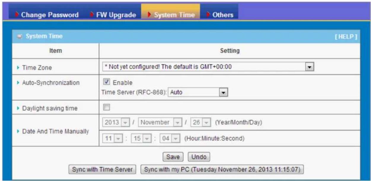
text_image
Change Password FW Upgrade System Time Others System Time [HELP] Item Setting Time Zone * Not yet configured! The default is GMT+00:00 Auto-Synchronization ✓ Enable Time Server (RFC-868): Auto Daylight saving time Date And Time Manually 2013 / November / 26 (Year/Month/Day) 11 : 15 : 04 (Hour:Minute:Second) Save Undo Sync with Time Server Sync with my PC (Tuesday November 26, 2013 11:15:07)- Time Zone: Select a time zone where this device locates.
- Auto-Synchronization: Check the "Enable" checkbox to enable this function. Besides, you can select a NTP time server to consult UTC time.
- Sync with Time Server: Click on the button if you want to set Date and Time by NTP Protocol.
- Sync with my PC: Click on the button if you want to set Date and Time using the PC's Date and Time.
Afterwards, click on "Save" to store your settings or click "Undo" to give up the changes.
3.3.3.4 Others
In this section you can do system backup, reset to default, system reboot settings and ping test.

text_image
Change Password FW Upgrade System Time Others Others [HELP] Item Setting Backup Setting Backup Reset to Default Reset Reboot Reboot Domain Name or IP address for Ping Test Ping Domain Name or IP address for Traceroute Traceroute- Backup Setting: You can backup your settings by clicking the "Backup" button and save it as a bin file. Once you want to restore these settings, please click Firmware Upgrade button and use the bin file you saved.
- Reset to Default: You can also reset this device to factory default settings by clicking the "Reset" button.
- Reboot: You can also reboot this device by clicking the "Reboot" button.
- Domain Name or IP address for Ping Test: This allows you to configure an IP, and ping the device. You can ping a specific IP to test whether it is alive.
- Domain Name or IP address for Traceroute: Traceroute is a network diagnostic tool for displaying the route (path) and measuring transit delays of packets across an IP network. Traceroute proceeds unless all (three) sent packets are lost more than twice, then the connection is lost and the route cannot be evaluated. Ping, on the other hand, only computes the final round-trip times from the destination point
3.3.4 MMI
3.3.4.1 Web UI
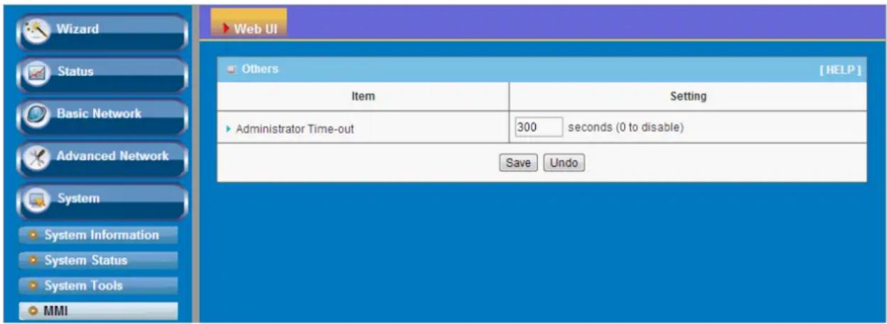
text_image
Wizard Status Basic Network Advanced Network System System Information System Status System Tools MMI Web UI Others [ HELP ] Item Setting Administrator Time-out 300 seconds (0 to disable) Save UndoYou can set UI administration time-out duration in this page. If the value is "0", means the time-out is unlimited.
CHAPTOR 4 Troubleshooting
This Chapter provides solutions to problems for the installation and operation of the WiFi Concurrent 300Mbps Business AP. You can refer to the following if you are having problems.
1 Why can't I configure the device even the cable is plugged and the LED is lit?
Do a Ping test to make sure that the WiFi Access Point is responding.
Note: It is recommended that you
Go to Start > Run.
- Type cmd.

text_image
Run Type the name of a program, folder, document, or Internet resource, and Windows will open it for you. Open: cmd OK Cancel Browse...- Press OK.
- Type ipconfig to get the IP of default gateway.
- Type "ping 192.168.1.1". Assure that you ping the correct IP Address assigned to the WiFi Concurrent 300Mbps Business AP. It will show four replies if you ping correctly.

text_image
Pinging 192.168.1.254 with 32 bytes of data: Reply from 192.168.1.1: bytes=32 time<1ms TTL=64 Reply from 192.168.1.1: bytes=32 time<1ms TTL=64 Reply from 192.168.1.1: bytes=32 time<1ms TTL=64 Reply from 192.168.1.1: bytes=32 time<1ms TTL=64Ensure that your Ethernet Adapter is working, and that all network drivers are installed properly. Network adapter names will vary depending on your specific adapter. The
installation steps listed below are applicable for all network adapters.
- Go to Start > Right click on "My Computer" > Properties.
- Select the Hardware Tab.
- Click Device Manager.
- Double-click on "Network Adapters".
- Right-click on Wireless Card bus Adapter or your specific network adapter.
- Select Properties to ensure that all drivers are installed properly.
- Look under Device Status to see if the device is working properly.
- Click "OK".
2 What can I do if my Ethernet connection does not work properly?
A. Make sure the RJ45 cable connects with the device.
B. Ensure that the setting on your Network Interface Card adapter is "Enabled".
C. If settings are correct, ensure that you are not using a crossover Ethernet cable, not all Network Interface Cards are MDI/MDIX compatible, and use a patch cable is recommended.
D. If the connection still doesn't work properly, then you can reset it to default.
3 Something wrong with the wireless connection?
A. Can't setup a wireless connection?
I. Ensure that the SSID and the encryption settings are exactly the same to the Clients.
II. Move the WiFi Concurrent 300Mbps Business AP and the wireless client into the same room, and then test the wireless connection.
III. Disable all security settings such as WEP, and MAC Address Control.
IV. Turn off the WiFi Concurrent 300Mbps Business AP and the client, then restart it and then turn on the client again.
V. Ensure that the LEDs are indicating normally. If not, make sure that the power and Ethernet cables are firmly connected.
VI. Ensure that the IP Address, subnet mask, gateway and DNS settings are correctly entered for the network.
VII. If you are using other wireless device, home security systems or ceiling fans, lights in your home, your wireless connection may degrade dramatically. Keep your product away from electrical devices that generate RF noise such as microwaves, monitors, electric motors...
B. What can I do if my wireless client can not access the Internet?
I. Out of range: Put the device closer to your client.
II. Wrong SSID or Encryption Key: Check the SSID or Encryption setting.
III. Connect with wrong AP: Ensure that the client is connected with the correct Access Point.
i. Right-click on the Local Area Connection icon in the taskbar.
ii. Select View Available Wireless Networks in Wireless Configure.
Ensure you have selected the correct available network.
iii. Reset the WiFi Concurrent 300Mbps Business AP to default setting
C. Why does my wireless connection keep dropping?
I. Antenna Orientation.
i. Try different antenna orientations for the WiFi Concurrent 300Mbps Business AP.
ii. Try to keep the antenna at least 6 inches away from the wall or other objects.
II. Try changing the channel on the WiFi Concurrent 300Mbps Business AP, and your Access Point and Wireless adapter to a different channel to avoid
interference.
III. Keep your product away from electrical devices that generate RF noise, like microwaves, monitors, electric motors, etc.
4 What to do if I forgot my encryption key?
- Go back to advanced setting to set up your Encryption key again.
- Reset the WiFi Concurrent 300Mbps Business AP to default setting
5 How to reset to default?
- Ensure the WiFi Concurrent 300Mbps Business AP is powered on
- Find the Reset button on the right side
- Press the Reset button for 8 seconds and then release.
- After the WiFi Concurrent 300Mbps Business AP reboots, it has back to the factory default settings.
Appendix A. Assigning a Static IP in Windows PC
When organizing your local network it's easier to assign each computer it's own IP address than using DHCP. Here we will take a look at doing it in XP, Windows 7, Windows 8 and Windows 8.1.
If you have a home network with several computes and devices, it's a good idea to assign each of them a specific address. If you use DHCP (Dynamic Host Configuration Protocol), each computer will request and be assigned an address every time it's booted up. When you have to do troubleshooting on your network, it's annoying going to each machine to figure out what IP they have.
Using Static IPs prevents address conflicts between devices and allows you to manage them more easily. Assigning IPs to Windows is essentially the same process, but getting to where you need to be varies between each version.

text_image
Search Everywhere network and sharing Red Stripe Dea Network and Sharing CenterWindows 7 or Windows 8.x
To change the computer's IP address in Windows 7, type network and sharing into the Search box in the Start Menu and select Network and Sharing Center when it comes up. If you are in Windows 8.x it will be on the Start Screen itself, like the screenshot at the top of this article.
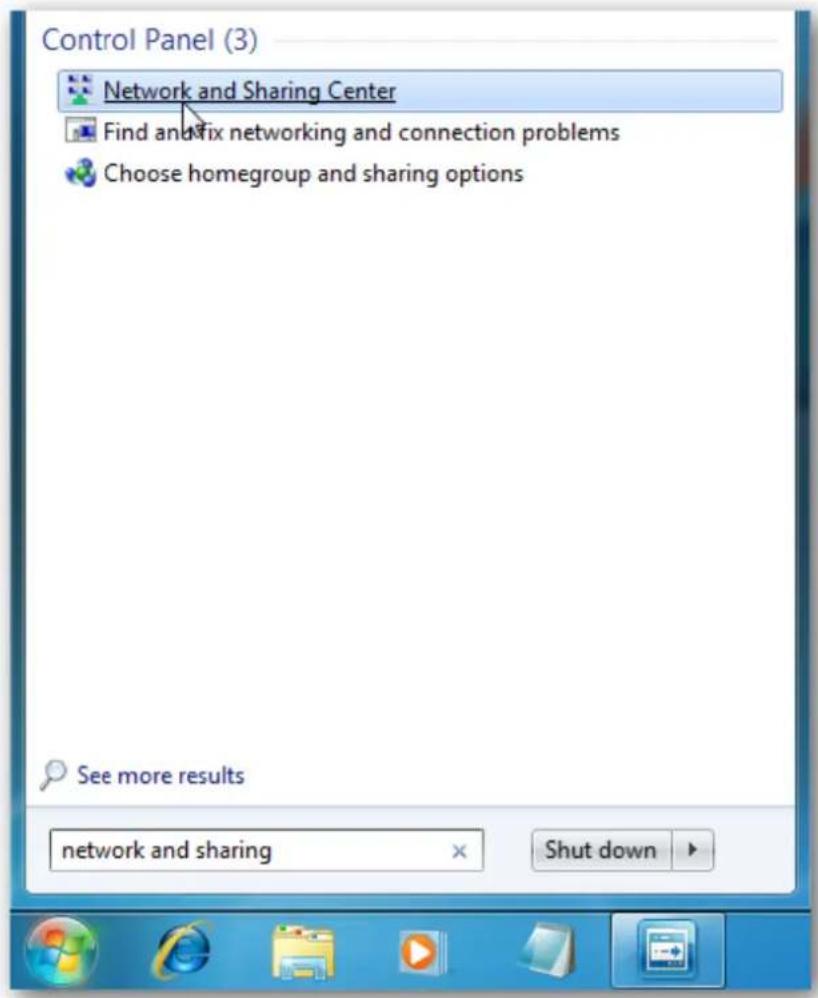
text_image
Control Panel (3) Network and Sharing Center Find an fix networking and connection problems Choose homegroup and sharing options See more results network and sharing Shut downThen when the Network and Sharing Center opens, click on Change adapter settings. This will be the same on Windows 7 or 8.x.
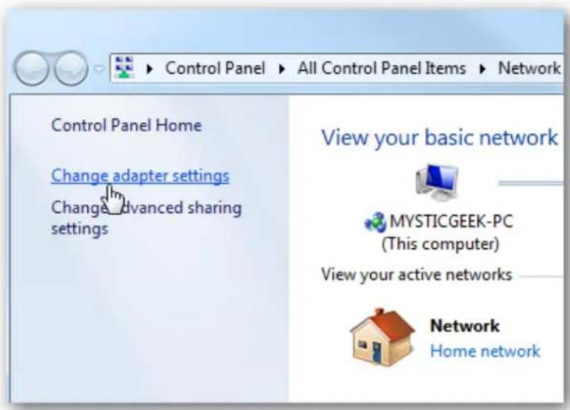
text_image
Control Panel Home Change adapter settings Change advanced sharing settings View your basic network MYSTICGEEK-PC (This computer) View your active networks Network Home networkRight-click on your local adapter and select Properties.
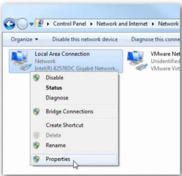
text_image
Control Panel ▶ Network and Internet ▶ Network Organize ▼ Disable this network device Diagnose this connec Local Area Connection Network Intel(R) 82578DC Gigabit Network... Disable Status Diagnose Bridge Connections Create Shortcut Delete Rename Properties VMware Net Unidentified VMware VirtIn the Local Area Connection Properties window highlight Internet Protocol Version 4 (TCP/IPv4) then click the Properties button.
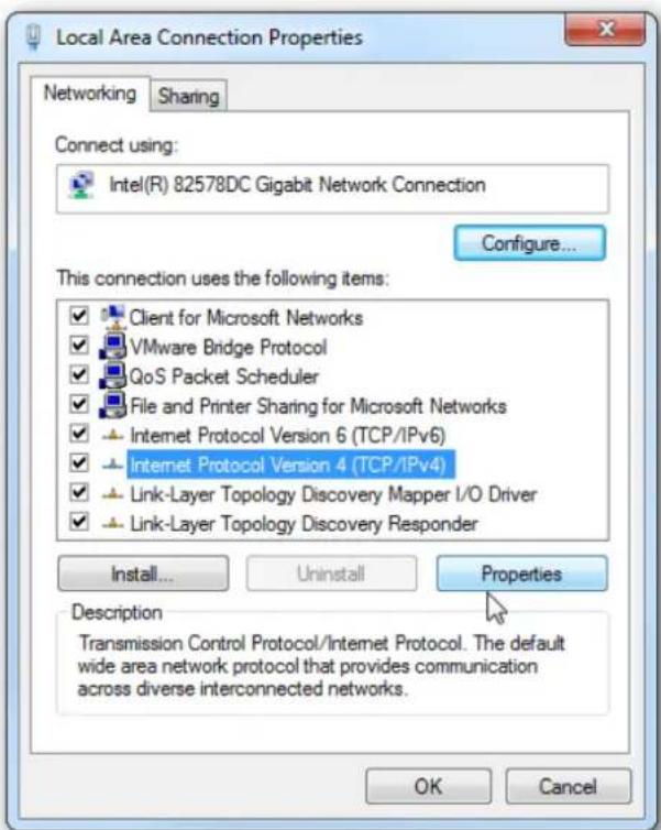
text_image
Local Area Connection Properties Networking Sharing Connect using: Intel(R) 82578DC Gigabit Network Connection Configure... This connection uses the following items: ✓ Client for Microsoft Networks ✓ VMware Bridge Protocol ✓ QoS Packet Scheduler ✓ File and Printer Sharing for Microsoft Networks ✓ Internet Protocol Version 6 (TCP/IPv6) ✓ Internet Protocol Version 4 (TCP/IPv4) ✓ Link-Layer Topology Discovery Mapper I/O Driver ✓ Link-Layer Topology Discovery Responder Install... Uninstall Properties Description Transmission Control Protocol/Internet Protocol. The default wide area network protocol that provides communication across diverse interconnected networks. OK CancelNow select the radio button Use the following IP address and enter in the correct IP, Subnet mask, and Default gateway that corresponds with your network setup. Then enter your Preferred and Alternate DNS server addresses. Here we're on a home network and using a simple Class C network configuration and Google DNS.
Check Validate settings upon exit so Windows can find any problems with the addresses
you entered. When you're finished click OK.
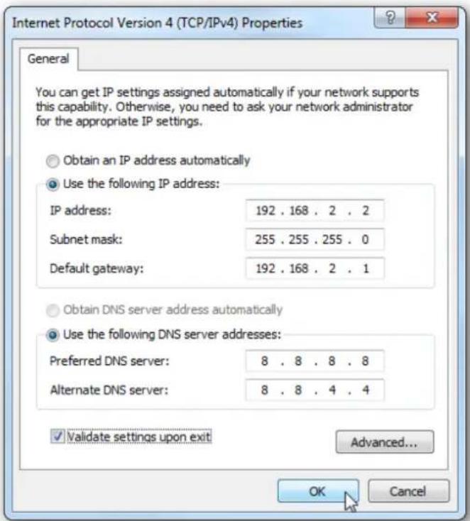
text_image
Internet Protocol Version 4 (TCP/IPv4) Properties General You can get IP settings assigned automatically if your network supports this capability. Otherwise, you need to ask your network administrator for the appropriate IP settings. Obtain an IP address automatically Use the following IP address: IP address: 192 . 168 . 2 . 2 Subnet mask: 255 . 255 . 255 . 0 Default gateway: 192 . 168 . 2 . 1 Obtain DNS server address automatically Use the following DNS server addresses: Preferred DNS server: 8 . 8 . 8 . 8 Alternate DNS server: 8 . 8 . 4 . 4 Validate settings upon exit Advanced... OK CancelNow close out of the Local Area Connections Properties window.

text_image
Local Area Connection Properties Networking Sharing Connect using: Intel(R) 82578DC Gigabit Network Connection Configure... This connection uses the following items: ✓ Client for Microsoft Networks ✓ VMware Bridge Protocol ✓ QoS Packet Scheduler ✓ File and Printer Sharing for Microsoft Networks ✓ Internet Protocol Version 6 (TCP/IPv6) ✓ Internet Protocol Version 4 (TCP/IPv4) ✓ Link-Layer Topology Discovery Mapper I/O Driver ✓ Link-Layer Topology Discovery Responder Install... Uninstall Properties Description Allows your computer to access resources on a Microsoft network. Close CancelWindows 7 will run network diagnostics and verify the connection is good. Here we had no problems with it, but if you did, you could run the network troubleshooting wizard.
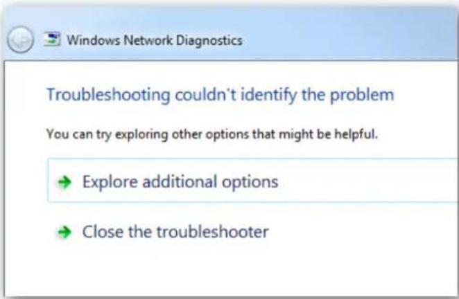
text_image
Windows Network Diagnostics Troubleshooting couldn't identify the problem You can try exploring other options that might be helpful. → Explore additional options → Close the troubleshooterNow you can open the command prompt and do an ipconfig to see the network adapter settings have been successfully changed.
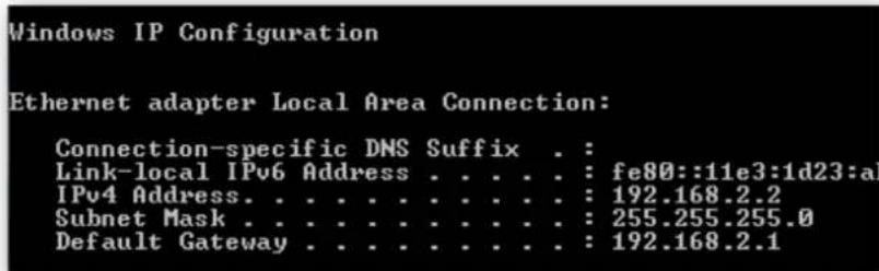
text_image
Windows IP Configuration Ethernet adapter Local Area Connection: Connection-specific DNS Suffix . : Link-local IPv6 Address . . . . . : fe80::11e3:1d23:a IPv4 Address. . . . . . . . . . : 192.168.2.2 Subnet Mask . . . . . . . . . : 255.255.255.0 Default Gateway . . . . . . . . . : 192.168.2.1Windows XP
In this example we're using XP SP3 Media Center Edition and changing the IP address of the Wireless adapter.
To set a Static IP in XP right-click on My Network Places and select Properties.
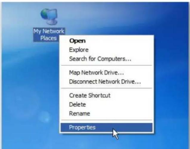
text_image
My Network Places Open Explore Search for Computers... Map Network Drive... Disconnect Network Drive... Create Shortcut Delete Rename PropertiesRight-click on the adapter you want to set the IP for and select Properties.
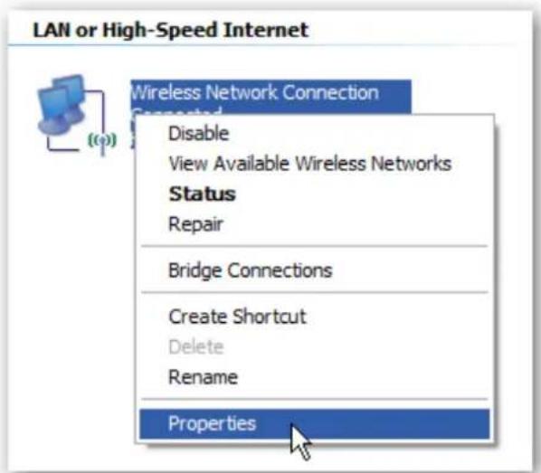
text_image
LAN or High-Speed Internet Wireless Network Connection Connected Disable View Available Wireless Networks Status Repair Bridge Connections Create Shortcut Delete Rename PropertiesHighlight Internet Protocol (TCP/IP) and click the Properties button.
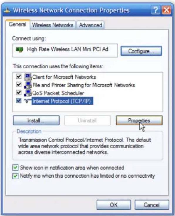
text_image
Wireless Network Connection Properties General Wireless Networks Advanced Connect using: High Rate Wireless LAN Mini PCI Ad Configure... This connection uses the following items: Client for Microsoft Networks File and Printer Sharing for Microsoft Networks QoS Packet Scheduler Internet Protocol (TCP/IP) Install... Uninstall Properties Description Transmission Control Protocol/Internet Protocol. The default wide area network protocol that provides communication across diverse interconnected networks. Show icon in notification area when connected Notify me when this connection has limited or no connectivity OK CancelNow change the IP, Subnet mask, Default Gateway, and DNS Server Addresses. When you're finished click OK.

text_image
Internet Protocol (TCP/IP) Properties General You can get IP settings assigned automatically if your network supports this capability. Otherwise, you need to ask your network administrator for the appropriate IP settings. Obtain an IP address automatically Use the following IP address: IP address: 192 . 168 . 2 . 5 Subnet mask: 255 . 255 . 255 . 0 Default gateway: 192 . 168 . 2 . 1 Obtain DNS server address automatically Use the following DNS server addresses: Preferred DNS server: 8 . 8 . 8 . 8 Alternate DNS server: 8 . 8 . 4 . 4 Advanced... OK CancelYou will need to close out of the Network Connection Properties screen before the changes go into effect.
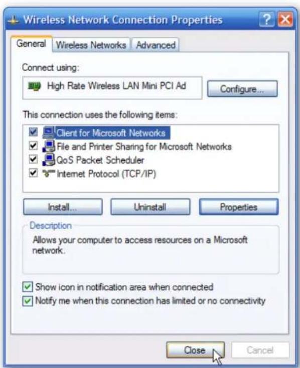
text_image
Wireless Network Connection Properties General Wireless Networks Advanced Connect using: High Rate Wireless LAN Mini PCI Ad Configure... This connection uses the following items: Client for Microsoft Networks File and Printer Sharing for Microsoft Networks QoS Packet Scheduler Internet Protocol (TCP/IP) Install... Uninstall Properties Description Allows your computer to access resources on a Microsoft network. Show icon in notification area when connected Notify me when this connection has limited or no connectivity Close CancelAgain you can verify the settings by doing an ipconfig in the command prompt. In case you're not sure how to do this, click on Start then Run.

text_image
Media Center All Programs Printers and Faxes Help and Support Search Run... Log Off Turn Off Computer startIn the Run box type in cmd and click OK.
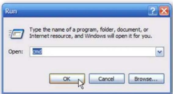
text_image
Run Type the name of a program, folder, document, or Internet resource, and Windows will open it for you. Open: cmd OK Cancel Browse...Then at the prompt type in ipconfig and hit Enter. This will show the IP address for the network adapter you changed.
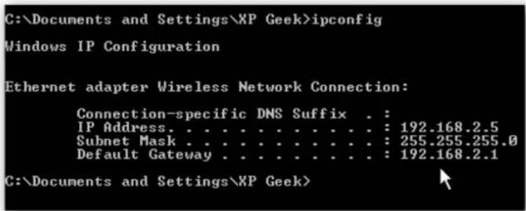
text_image
C:\Documents and Settings\XP Geek>ipconfig Windows IP Configuration Ethernet adapter Wireless Network Connection: Connection-specific DNS Suffix . : IP Address. . . . . . . . . . . . . : 192.168.2.5 Subnet Mask . . . . . . . . . . . . : 255.255.255.0 Default Gateway . . . . . . . . . . . : 192.168.2.1 C:\Documents and Settings\XP Geek>If you have a small office or home network, assigning each computer a specific IP address makes it a lot easier to manage and troubleshoot network connection problems.
[Source: How to Assign a Static IP Address in Windows 7, 8, XP, or Vista;
http://www.howtogeek.com/howto/19249/how-to-assign-a-static-ip-address-in-xp-vista-or-windows-7/]
Appendix B. Licensing information
This product includes copyrighted third-party software licensed under the terms of the GNU General Public License. Please refer to the GNU General Public License below to check the detailed terms of this license.
The following parts of this product are subject to the GNU GPL, and those software packages are copyright by their respective authors.
Linux Kernel GPLv2 Linux-2.6.21
busybox GPLv2 busybox_1.3.2
bridge-utils GPLv2 bridge-utils 1.1
udhcp server GPLv2 udhcp-0.9.9
udhcp client
fdisk GPLv2 util-linux 2.12q
mke2fs, e2fsck GPLv2 e2fsprogs v1.40.2
samba GNUv2 samba 3.0.20
wireless tools GPLv2 wireless tools
vsfptd GPLv2 vsftpd-2.0.3
Transmission MIT Transmission-1.74
mt-daapd GNUv2 mt-daapd-0.2.4
dnrd GNUv2 DNRD-2.17
libcurl cURL-7.19.6
OpenSSL BSD openssl-1.00b3
ntfs-3g GNUv2 ntfs-3g-2009.4.4
Zebra GNUv2 zebra-0.95a
Version 2, June 1991
Copyright (C) 1989, 1991 Free Software Foundation, Inc. 59 Temple Place, Suite 330, Boston, MA 02111-1307 USA
Everyone is permitted to copy and distribute verbatim copies of this license document, but changing it is not allowed.
Preamble
The licenses for most software are designed to take away your freedom to share and change it. By contrast, the GNU General Public License is intended to guarantee your freedom to share and change free software--to make sure the software is free for all its users. This General Public License applies to most of the Free Software Foundation's software and to any other program whose authors commit to using it. (Some other Free Software Foundation software is covered by the GNU Library General Public License instead.) You can apply it to your programs, too.
When we speak of free software, we are referring to freedom, not price. Our General Public Licenses are designed to make sure that you have the freedom to distribute copies of free software (and charge for this service if you wish), that you receive source code or can get it if you want it, that you can change the software or use pieces of it in new free programs; and that you know you can do these things.
To protect your rights, we need to make restrictions that forbid anyone to deny you these rights or to ask you to surrender the rights. These restrictions translate to certain responsibilities for you if you distribute copies of the software, or if you modify it.
For example, if you distribute copies of such a program, whether gratis or for a fee, you must give the recipients all the rights that you have. You must make sure that they, too, receive or can get the source code. And you must show them these terms so they know their rights.
We protect your rights with two steps: (1) copyright the software, and (2) offer you this license which gives you legal permission to copy, distribute and/or modify the software.
Also, for each author's protection and ours, we want to make certain that everyone understands that there is no warranty for this free software. If the software is modified by someone else and passed on, we want its recipients to know that what they have is not the original, so that any problems introduced by others will not reflect on the original authors' reputations.
Finally, any free program is threatened constantly by software patents. We wish to avoid the danger that redistributors of a free program will individually obtain patent licenses, in effect making the program proprietary. To prevent this, we have made it clear that any patent must be licensed for everyone's free use or not licensed at all.
The precise terms and conditions for copying, distribution and modification follow.
GNU GENERAL PUBLIC LICENSE
TERMS AND CONDITIONS FOR COPYING, DISTRIBUTION AND MODIFICATION
- This License applies to any program or other work which contains a notice placed by the copyright holder saying it may be distributed under the terms of this General Public License. The "Program", below, refers to any such program or work, and a "work based on the Program" means either the Program or any derivative work under copyright law: that is to say, a work containing the Program or a portion of it, either verbatim or with modifications and/or translated into another language. (Hereinafter, translation is included without limitation in the term "modification".) Each licensee is addressed as "you".
Activities other than copying, distribution and modification are not covered by this License; they are outside its scope. The act of running the Program is not restricted, and the output from the Program is covered only if its contents constitute a work based on the Program (independent of having been made by running the Program). Whether that is true depends on what the Program does.
- You may copy and distribute verbatim copies of the Program's source code as you receive it, in any medium, provided that you conspicuously and appropriately publish on each copy an appropriate copyright notice and disclaimer of warranty; keep intact all the notices that refer to this License and to the absence of any warranty; and give any other recipients of the Program a copy of this License along with the Program.
You may charge a fee for the physical act of transferring a copy, and you may at your option offer warranty protection in exchange for a fee.
- You may modify your copy or copies of the Program or any portion of it, thus forming a work based on the Program, and copy and distribute such modifications or work under the terms of Section 1 above, provided that you also meet all of these conditions:
a) You must cause the modified files to carry prominent notices stating that you changed the files and the date of any change.
b) You must cause any work that you distribute or publish, that in whole or in part contains or is derived from the Program or any part thereof, to be licensed as a whole at no charge to all third parties under the terms of this License.
c) If the modified program normally reads commands interactively when run, you must cause it, when started running for such interactive use in the most ordinary way, to print or display an announcement including an appropriate copyright notice and a notice that there is no warranty (or else, saying that you provide a warranty) and that users may redistribute the program under these conditions, and telling the user how to view a copy of this License. (Exception: if the Program itself is interactive but does not normally print such an announcement, your work based on the Program is not required to print an announcement.)
These requirements apply to the modified work as a whole. If identifiable sections of that work are not derived from the Program, and can be reasonably considered independent and separate works in themselves, then this License, and its terms, do not apply to those sections when you distribute them as separate works. But when you distribute the same sections as part of a whole which is a work based on the Program, the distribution of the whole must be on the terms of this License, whose permissions for other licensees extend to the entire whole, and thus to each and every part regardless of who wrote it.
Thus, it is not the intent of this section to claim rights or contest your rights to work written entirely by you; rather, the intent is to exercise the right to control the distribution of derivative or collective works based on the Program.
In addition, mere aggregation of another work not based on the Program with the Program (or with a work based on the Program) on a volume of a storage or distribution medium does not bring the other work under the scope of this License.
- You may copy and distribute the Program (or a work based on it, under Section 2) in object code or executable form under the terms of Sections 1 and 2 above provided that you also do one of the following:
a) Accompany it with the complete corresponding machine-readable source code, which must be distributed under the terms of Sections 1 and 2 above on a medium customarily used for software interchange; or,
b) Accompany it with a written offer, valid for at least three years, to give any third party, for a charge no more than your cost of physically performing source distribution, a complete machine-readable copy of the corresponding source code, to be distributed under the terms of Sections 1 and 2 above on a medium customarily used for software interchange; or,
c) Accompany it with the information you received as to the offer to distribute corresponding source code. (This alternative is allowed only for noncommercial distribution and only if you received the program in object code or executable form with such an offer, in accord with Subsection b above.)
The source code for a work means the preferred form of the work for making modifications to it. For an executable work, complete source code means all the source code for all modules it contains, plus any associated interface definition files, plus the scripts used to control compilation and installation of the executable. However, as a special exception, the source code distributed need not include anything that is normally distributed (in either source or binary form) with the major components (compiler, kernel, and so on) of the operating system on which the executable runs, unless that component itself accompanies the executable.
If distribution of executable or object code is made by offering access to copy from a designated place, then offering equivalent access to copy the source code from the same place counts as distribution of the source code, even though third parties are not compelled to copy the source along with the object code.
-
You may not copy, modify, sublicense, or distribute the Program except as expressly provided under this License. Any attempt otherwise to copy, modify, sublicense or distribute the Program is void, and will automatically terminate your rights under this License. However, parties who have received copies, or rights, from you under this License will not have their licenses terminated so long as such parties remain in full compliance.
-
You are not required to accept this License, since you have not signed it. However, nothing else grants you permission to modify or distribute the Program or its derivative works. These actions are prohibited by law if you do not accept this License. Therefore, by modifying or distributing the Program (or any work based on the Program), you indicate your acceptance of this License to do so, and all its terms and conditions for copying, distributing or modifying the Program or works based on it.
-
Each time you redistribute the Program (or any work based on the Program), the recipient automatically receives a license from the original licensor to copy, distribute or modify the Program subject to these terms and conditions. You may not impose any further restrictions on the recipients' exercise of the rights granted herein. You are not responsible for enforcing compliance by third parties to this License.
-
If, as a consequence of a court judgment or allegation of patent infringement or for any other reason (not limited to patent issues), conditions are imposed on you (whether by court order, agreement or otherwise) that contradict the conditions of this License, they do not excuse you from the conditions of this License. If you cannot distribute so as to satisfy simultaneously your obligations under this License and any other pertinent obligations, then as a consequence you may not distribute the Program at all. For example, if a patent license would not permit royalty-free redistribution of the Program by all those who receive copies directly or indirectly through you, then the only way you could satisfy both it and this License would be to refrain entirely from distribution of the Program.
If any portion of this section is held invalid or unenforceable under any particular circumstance, the balance of the section is intended to apply and the section as a whole is intended to apply in other circumstances.
It is not the purpose of this section to induce you to infringe any patents or other property right claims or to contest validity of any such claims; this section has the sole purpose of protecting the integrity of the free software distribution system, which is implemented by public license practices. Many people have made generous contributions to the wide range of software distributed through that system in reliance on consistent application of that system; it is up to the author/donor to decide if he or she is willing to distribute software through any other system and a licensee cannot impose that choice.
This section is intended to make thoroughly clear what is believed to be a consequence of the rest of this License.
-
If the distribution and/or use of the Program is restricted in certain countries either by patents or by copyrighted interfaces, the original copyright holder who places the Program under this License may add an explicit geographical distribution limitation excluding those countries, so that distribution is permitted only in or among countries not thus excluded. In such case, this License incorporates the limitation as if written in the body of this License.
-
The Free Software Foundation may publish revised and/or new versions of the General Public License from time to time. Such new versions will be similar in spirit to the present version, but may differ in detail to address new problems or concerns.
Each version is given a distinguishing version number. If the Program specifies a version number of this License which applies to it and "any later version", you have the option of following the terms and conditions either of that version or of any later version published by the Free Software Foundation. If the Program does not specify a version number of this License, you may choose any version ever published by the Free Software Foundation.
- If you wish to incorporate parts of the Program into other free programs whose distribution conditions are different, write to the author to ask for permission. For software which is copyrighted by the Free Software Foundation, write to the Free Software Foundation; we sometimes make exceptions for this. Our decision will be guided by the two goals of preserving the free status of all derivatives of our free software and of promoting the sharing and reuse of software generally.
NO WARRANTY
-
BECAUSE THE PROGRAM IS LICENSED FREE OF CHARGE, THERE IS NO WARRANTY FOR THE PROGRAM, TO THE EXTENT PERMITTED BY APPLICABLE LAW. EXCEPT WHEN OTHERWISE STATED IN WRITING THE COPYRIGHT HOLDERS AND/OR OTHER PARTIES PROVIDE THE PROGRAM "AS IS" WITHOUT WARRANTY OF ANY KIND, EITHER EXPRESSED OR IMPLIED, INCLUDING, BUT NOT LIMITED TO, THE IMPLIED WARRANTIES OF MERCHANTABILITY AND FITNESS FOR A PARTICULAR PURPOSE. THE ENTIRE RISK AS TO THE QUALITY AND PERFORMANCE OF THE PROGRAM IS WITH YOU. SHOULD THE PROGRAM PROVE DEFECTIVE, YOU ASSUME THE COST OF ALL NECESSARY SERVICING, REPAIR OR CORRECTION.
-
IN NO EVENT UNLESS REQUIRED BY APPLICABLE LAW OR AGREED TO IN WRITING WILL ANY COPYRIGHT HOLDER, OR ANY OTHER PARTY WHO MAY MODIFY AND/OR REDISTRIBUTE THE PROGRAM AS PERMITTED ABOVE, BE LIABLE TO YOU FOR DAMAGES, INCLUDING ANY GENERAL, SPECIAL, INCIDENTAL OR CONSEQUENTIAL DAMAGES ARISING OUT OF THE USE OR INABILITY TO USE THE PROGRAM (INCLUDING BUT NOT LIMITED TO LOSS OF DATA OR DATA BEING RENDERED INACCURATE OR LOSSES SUSTAINED BY YOU OR THIRD PARTIES OR A FAILURE OF THE PROGRAM TO OPERATE WITH ANY OTHER PROGRAMS), EVEN IF SUCH HOLDER OR OTHER PARTY HAS BEEN ADVISED OF THE POSSIBILITY OF SUCH DAMAGES.
END OF TERMS AND CONDITIONS
Notification of Compliance
Appendix C
Europe - EU Declaration of Conformity

For complete DoC please visit
http://global.level1.com/downloads.php?action=init
GPL License Agreement
GPL may be included in this product, to view the GPL license agreement goes to http://download.level1.com/level1/gpl/GPL.pdf
For GNU General Public License (GPL) related information, please visit http://global.level1.com/downloads.php?action=init