VCA-400S - AV Extender Smart-AVI - Free user manual and instructions
Find the device manual for free VCA-400S Smart-AVI in PDF.


| Product Type | AV Extender |
| Brand | Smart-AVI |
| Model | VCA-400S |
| Dimensions (W x D x H) | 10.2 x 5.1 x 2.5 cm (4 x 2 x 1 in) |
| Weight | 0.3 kg (0.66 lbs) |
| Power Supply | DC 5V, 1A (adapter included) |
| Power Consumption | 2.5W (max) |
| Video Input | VGA (male connector) |
| Video Output | VGA (female connector) |
| Audio Input | 3.5mm stereo jack (male) |
| Audio Output | 3.5mm stereo jack (female) |
| Maximum Extension Distance | 300 meters (984 ft) |
| Supported Resolutions | Up to 1920x1200 @ 60Hz |
| Bandwidth | 350 MHz |
| Operating Temperature | 0°C to 50°C (32°F to 122°F) |
| Storage Temperature | -20°C to 60°C (-4°F to 140°F) |
| Humidity | 20% to 80% (non-condensing) |
| Housing Material | Metal |
| LED Indicators | Power and Signal Status |
| Warranty | 1 year limited |
| Cleaning Instructions | Wipe with a dry, soft cloth. Do not use liquids. |
| Safety Precautions | Use only with provided power adapter. Keep away from moisture. |
| Spare Parts Availability | Contact Smart-AVI support for replacement cables or power adapters. |
| Repairability | No user-serviceable parts inside. Contact qualified service. |
Frequently Asked Questions - VCA-400S Smart-AVI
User questions about VCA-400S Smart-AVI
0 question about this device. Answer the ones you know or ask your own.
Ask a new question about this device
Download the instructions for your AV Extender in PDF format for free! Find your manual VCA-400S - Smart-AVI and take your electronic device back in hand. On this page are published all the documents necessary for the use of your device. VCA-400S by Smart-AVI.
USER MANUAL VCA-400S Smart-AVI
Technical Specifications
| reviecerdnarettimsnarT | |
| oedIV ediV ediV | |
| Bandwidth | 400MHz |
| Analog signal Level | 1 volt |
| Impedance | 75 ohms |
| Connector | High density HD15 |
| Format | VGAYSVGAYXGA/UXGA/RGBH/RGsB |
| mpS | TTL horizontal SyncRange: 15 to 130 KHzVertical Sync Range 30 to 120 Hz |
| Audidi | |
| Bandwidth | 20 KHz |
| Signal level | OdB |
| Impedance | 10K ohms |
| Connector | 3.5mm jack socket |
| System Cable | |
| Type | Cat5 UTP EIA 568A |
| Connector | RJ45 |
| Powere | |
| Requirements | 5V DC @500mA |
| Connector | 5x2.1 DC Jack |
© Copyright 2007 Smart-AVI, All Rights Reserved
Notice
eviecerdnarettimsnarT
The information contained in this document is subject to change without notice. Smart-AVI makes no warranty of any kind with regard to this material, including but not limited to, implied warranties of merchantability and fitness for any particular purpose.
Smart-AVI will not be liable for errors contained herein or for incidental or consequential damages in connection with the furnishing, performance or use of this material.
No part of this document may be photocopied, reproduced or translated into another language with out prior written consent from Smart-AVI.
For the complete manual, visit www.smartavi.com.
Smart-AM
Smart Audio Video Integration
User Manual
VCA400

natural_image
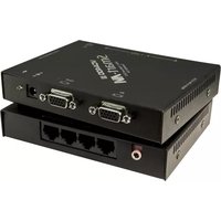
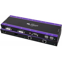
Two black electronic devices with ports and connectors, no visible text or symbols on the device surfaces.Use a single CAT5 to broadcast high resolution UXGA and stereo audio to 4 locations1000ft away
Smart-AM
3111 Winona Ave., Suite 101
Burbank, California 91504
Phone: (818) 565-0011
Facsimile: (818) 565-0020
www.smartavi.com
Introduction
The VCA400 allows transmission of high definition video and stereo audio signals over a standard CAT-5 UTP cable over distances of up to 1000 ft.
Features
■ Uses easy to install, inexpensive CAT5.
■ Output reaches up to 1,000 feet.
■ Resolutions up to 1900x1200.
■ 300 MHz Bandwidth.
■ Sends high-resolution VGA and stereo audio signals from one source to up to 4 devices.
■ Compatible with VGA, XGA, Sun, MAC and SGI signals.
■ Sync Format / Polarity Preservation.
■ High ground loop immunity.
■ Built-in lightning, power surge and transient protection.
■ Designated trimmer in the remote unit to compensate for cable length.
■ Compact Metal Case Enclosure.
■ Remote Units come with Buffered Outputs.
■ External power supply.
What's in the box?
| noitpircscD | |
| 4 port VCA UXGA/Audio Transmitter | VCA-TX400 |
| 5VDC 1A Power Supply | PS-5D1A-US |
| VGA cable Male to Female | CC-VGAMM-06 |
| Optional Equipment | |
| VCAT-RX Receiver Unit | VCA-RX100 |
Installation Diagram
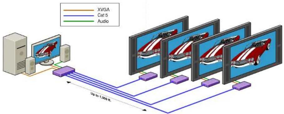
flowchart
graph TD
    A["Server"] --> B["Computer"]
    B --> C["Up to 1,000 ft"]
    C --> D["Cat 5"]
    C --> E["Audio"]
    D --> F["Computer"]
    E --> G["Computer"]
    style A fill:#f9f,stroke:#333
    style B fill:#ccf,stroke:#333
    style C fill:#cfc,stroke:#333
    style D fill:#fcc,stroke:#333
    style E fill:#cff,stroke:#333
    style F fill:#ffc,stroke:#333
    style G fill:#cfc,stroke:#333
VCAT Transmitter Installation Diagram
VCAT Receiver Installation Diagram
Connecting The Transmitter Connecting The Transmitter Adjusting and Fine Tuning the Signal
- Connect the output of the computer video card to the video input of the transmitter using the included male to male video cable.
- Connect local monitor to the VGA out of the transmitter.
- Connect the audio output cable from the computer to the transmitter
- In the back of the unit connect the CAT5 cable that will connect to the receiver unit.
- Connect the power supply.
*NOTE: You can not use RS232 and IR at the same time.
Connecting The Receiver Connecting The Receiver
- Connect CAT5 cable (coming from the transmitter) to the back of the receiver.
- Connect monitors to the VGA out connectors on the front of the receiver.
- Connect the speakers to the audio out connectors on the front of the receiver unit.
- Connect the power supply.

chemical
Molecular structure diagram showing red, black, and green atoms with bondsIn order to fine tune the signal, adjust the individual dials one at a time starting with GREEN, then BLUE, and lastly RED. As you turn the dials you will notice the colors slightly change as you increase or decrease the strength.
Preparing & Connecting System CAT5 Cable Following is the wiring standard for terminating CAT 5 cable using RJ-45 connector:
Pair 1 Pins 1 & 2 Pair 2 Pins 3 & 6 Pair 3 Pins 4 & 5 Pair 4 Pins 7 & 8


Connectors:
Capacitance:
Conductor Gauge: Impedance:
RJ-45
14 pf/ft (46.2 pf/m)
24 AWG
100 +/- 15 ohms
4 - Pair
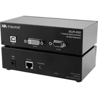
Brand : Smart-AVI
Model : VCA-400S
Category : AV Extender