
8127 - Measurement Kyoritsu - Free user manual and instructions
Find the device manual for free 8127 Kyoritsu in PDF.

| Brand | Kyoritsu |
| Model | 8127 |
| Product Type | Digital Clamp Meter |
| Measurement Category | AC/DC Current, AC/DC Voltage, Resistance, Capacitance, Frequency, Temperature, Diode Check, Continuity |
| AC Current Range | 0.01 A to 600 A (auto-ranging) |
| DC Current Range | 0.01 A to 600 A (auto-ranging) |
| AC Voltage Range | 0.1 mV to 600 V (auto-ranging) |
| DC Voltage Range | 0.1 mV to 600 V (auto-ranging) |
| Resistance Range | 0.1 Ω to 40 MΩ (auto-ranging) |
| Capacitance Range | 0.01 nF to 4000 μF |
| Frequency Range | 0.01 Hz to 10 MHz |
| Temperature Range | -50°C to 1000°C (with type K thermocouple) |
| Display | 4000-count LCD with backlight |
| Safety Rating | CAT III 600 V, CAT II 1000 V |
| Power Supply | 2 x AAA batteries (1.5 V) |
| Battery Life | Approximately 100 hours (typical) |
| Auto Power Off | Yes, after 15 minutes of inactivity |
| Jaw Opening | 30 mm (1.2 inches) |
| Dimensions | 190 x 70 x 40 mm (7.5 x 2.8 x 1.6 inches) |
| Weight | Approximately 250 g (8.8 oz) including batteries |
| Accessories Included | Test leads, thermocouple, batteries, carrying case, manual |
| Repairability | User-replaceable fuses and batteries; professional service recommended for other repairs |
| Cleaning and Maintenance | Wipe with a damp cloth; do not use solvents. Store in dry environment. |
Frequently Asked Questions - 8127 Kyoritsu
User questions about 8127 Kyoritsu
0 question about this device. Answer the ones you know or ask your own.
Ask a new question about this device
Download the instructions for your Measurement in PDF format for free! Find your manual 8127 - Kyoritsu and take your electronic device back in hand. On this page are published all the documents necessary for the use of your device. 8127 by Kyoritsu.
USER MANUAL 8127 Kyoritsu
POWER CLAMP SENSOR Series
MODEL 8124/8125/8126/8127

Factory: Elime, Japan
www.kew-ltd.co.jp
522
92-1140二
1. Safety warnings
This instrument has been designed, manufactured and tested according to ARMC. Safety requirements for Electronic Measuring apparatus, and delivered in the best condition after processing quality control tests. This information manual contains warnings and safety rules which have to be observed by the user to ensure operation of the instrument and to maintain it in safe condition. Therefore, read through these operating instructions before using the instrument.
WARNING
● Read through and understand instructions contained
- Keep the manual at hand to enable quick referen whenever necessary.
● The instrument is to be used only in its intended
The operating instructions described in the manual must be checked.
● Understand and follow all the safety instructions contained in the manual, it is essential that the above instructions are adhered to. Failure to follow the above instructions may cause injury and or instrument damage. Kyontau is by no means liable for any damage resulting from the instrument in contradiction to this cautionary note.
The symbol indicated on the instrument, means that the user must refer to the related parts in the manual for
sare operation of the instrument. It is essential to read the instructions wherever the △ several appears in line
△ DANGER is reserved for conditions and actions that are likely to cause serious or fatal injury. △ WARNING is reserved for conditions and actions that can cause serious or fatal injury. △ CAUTION is reserved for conditions and actions that can cause minor injury or instrument damage.
DANGER
- Never make measurement on a circuit in which the electrical potential exceeds AC 300V using MODU8127 and A600V using MODU8124, 8125 and 8126.
- Do not make measurement when thunder rumbing. If the instrument is in use, stop the measurement immediately and remove the instrument from the measured chest.
- Do not attempt to make measurement in the presence of flammaole gassas. Otherwise, the use of the instrument may cause sparking, which can lead to an explosion.
● The transformer jewa are made of metal tips are not completely insulated. Be especially careful about the possible shorting where the measured object has exposed metal parts.
- Never attempt to use the instrument if it's a surface or your hand are well.
● Do not exceed the maximum allowable measuring range.
WARNING
● Never attempt to make any measurement. If any abnormal conditions are noted, such as broken and exposed metal parts.
- Do not install substitute parts or make any modification to the instrument. Return the to the distributor from who you purchased this instrument for repair or re-calibration in case of suspected faulty operation.
● Always keep your fingers and hands behind the panels on the instrument to avoid the possible shock hazard.
& CAUTION
● Do not stop on or pinch the cord to prevent the jacket
● The output connector shall be removed or connected without clamping a conductor. Otherwise, it may cause a failure.
● Do not expose the instrument to direct sunlight, high temperatures, humidity or dry
● Never give shocks, such as vibration or drop, which may damage the instrument.
- Use a stamp cloth and detergent for cleaning the instrument. Do not use abrasive or solvents.
Equity symbols
| A | Ruler is the instructions in the manual |
| Indicates a Instrument with double or replaced invatlon | |
| Indicates that this Instrument can come on care construction | |
| Indicates AC |
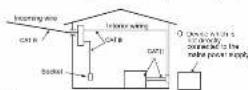
○ Measurement Category
To ensure - save operation of measuring instruments, IEC 61010 establishes safety standards for various electrical environments, categorized as O to CAT IV, and called measurement categories. Higher-numbered categories correspond to electrical environments with greater momentary energy, so a measuring instrument designed for CAT III environments can endure greater momentary energy and so on design for CAT II.
Circuits which are not directly connected to the
CATT II : Electrical circuits of equipment connected to an AC
electrical outlet by a power cord. CAT III. Primary electrical circuits of the equipment
connected directly to the distribution panel,
teachers from the distribution panel to outlets. CAT IV: The circuit from the service drop to the service entrance, and to the power meter end primary overcurrent protection device distribution panel.
2. Features
● This is a clamp sensor for our Power meter. ● Designed to international safety standard IEC610102002 CAT III Pollution Degree 2
- Instrument layout
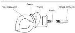
Barrier: II is a part providing protection against electrical shock and ensuring the minimum required air and coverage distances.
- Din plug pin assignment
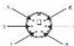
3: GND pin 5: Output signal pin 1, 2, 4 and 6: No use
Above figure shows the pin assignment seen Clamo sensor from output connector part. The figure of the pin assignment of connection terminal is symmetrical to above figure.
- Specifications
| Model | IP 26 | IP 25 | IP 24 | IP 23 |
| Fiscal stage | AC100MMx147MHz | AC050Ams(70Hz) | AC000mmx(80Hz) | AC000mmx(43Hz) |
| Out of village | AO - 600mVAC050mA/AC100ACh/mV-4 | AO - 500mVAC050mA/AC050Acm/mV-3 | AO - 500mVAC050mA/AC050Ax2.5mA/NA | AO - 600mVAC050mA/AC050Ax2.5mA/NA |
| Measureing arc | C - 100A | AO - 500A | AO - 500A | AO - 100A |
| Access flow from the town | L050MHz 1.0MHz/100MHz1.0MHz/2.0MHz/100MHz | L050 MHz 1.0MHz/100MHz1.0MHz/2.0MHz/100MHz | L050 MHz 1.0MHz/100MHz1.0MHz/2.0MHz/100MHz | L050MHz 1.0MHz/100MHz1.0MHz/2.0MHz/100MHz |
| Class channel rating | Eg. in km 100K / 45-85K | Eg. in km 100K / 300K / 45-85K | Eg. in km 100K / 200K / 45-85K | Eg. in km 100K / 100K / 45-85K |
| Capacitor scale (in feet) | ||||
| Opening lead strength | 232.5 V, relative to 15% or less than convection | |||
| Opening lead strength | 0 - 50 C, related by 15% or less than convection | |||
| Opening lead strength | -20 - 60 C, relative humidity, 85% or less than convection | |||
| Order per minute range | NC100mm con buffer (100 m2) | NC100mm con buffer (100 m2) | NC100mm con buffer (100 m2) | NC100mm con buffer (100 m2) |
| Out of impedance | Approx. 1Ω | Approx. 2Ω | Approx. 5Ω | Approx. 11Ω |
| Location features | Airflow up to AC05m, Intrams | |||
| Applicable distance | AC100MHz 1.0MHz/100MHzMeasurement CAT II 600mmRatloner Series 2EC100MHz 1.0 kHz | EC 600MHz 1.0 kHz/100MHzMeasurement CAT II 550mmRatloner Series 2EC 600MHz 1.0 kHz | ||
| Environmental standing | EL Parti Discitive incline | |||
| Weather level voltage | AC050MHz (DC98) per Sarebetween Low and above两者between exposure and pump in terminalbetween Low and supply terminal | AC050MHz (DC98) per Sarebetween DC98 and above两者between low and supply terminalbetween Low and subtable | ||
| Flood level radiation | 500Ω per gridded at 100kHzbetween Low and above两者between exposure and pump in terminalbetween Low and supply terminal | 500MHz (DC98) per Sarebetween DC98 and above两者between low and subtable | ||
| Crude size | Apex. 5mm in diameter (max)1250A x 2200A x 340mm | Apex. 50mm x 2200A x 340mm | Apex. 50mm x 2200A x 340mm | Apex. 50mm x 2200A x 340mm |
| Dimension | 1250A x 2200A x 340mm | 1250A x 2200A x 340mm | ||
| Colour length | Apex. 5m | |||
| Out of time | VIN DENS P/N | |||
| Weight | Apex. 50kg | Apex. 200kg | Apex. 250kg | Apex. 100kg |
| Accession | Intricate manual | |||
| Cable marker | ||||
| Option | VDD - 114 (Figure 6) (Water label)VDDS - 114 (Extension block) | |||
6. Operating Instructions
DANGER
● Never make measurement on a circuit in which the electrical potential exceeds 300V using MODE127 and AC600V using MODELS124, 8125 and 8126 in order to avoid possible shock hazard.
The transformer jaws are made of metal, are not completely insulated. Be especially careful about the positive sheeting where the measure object has exposed metal parts.
CAUTION
● Take sufficient care to avoid shock, vibration of excessive force when handling the instrument. Otherwise, precisely adjusted transformer jaws damaged.
- When transformer jewe do not fully close, close them by force, but make them free to try again. It a foreign substance is stuck, tips, remove it.
- When making current measurements, keep the transformer jaws fully closed.
Otherwise, accurate measurements cannot be taken. Maximum conductor size is as follows.
MCO-18124 500-40 in diameter
MODEL 125-0-26.43 mm in diameter MODEL 8127 - 2mm in diameter
● Hold the inserting part (except for the cable) and disconnect the output corrector from the measuring instrument so as not to cause a break in the cord.
her lips
will be never try move and in the
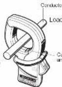
mark (Power source to load), which is indicated on the transformer laws, with the current flowing direction order to synchronize the phases of measured current and output voltage. Ensure that the tips of transformer laws are limit closed.
6.2 Setting for Power meter
When using any of these sensors 8005 NEW 6315, please refer to the instruction manual, cit which you're using, and carefully check sensor settings and available current ranges.
6-1 Measurement procedures
(1) Connect the Output connector to the Input terminal of
(2) Press the Trigger to open the transformer jaws and
clamp onto one conductor. In this case, the measured conductor shall be at the center of the class.
When connecting a sensor with a Power meter (our Power meter, MODE300, etc.) match the arrow

This instrument satisfies the marking requirement defined in the WEEE Directix (2002/96/EC). This symbol indicates separate collection for electrical and electronic equipment.
Brand : Kyoritsu
Model : 8127
Category : Measurement