
KEW 8035 - Measurement Kyoritsu - Free user manual and instructions
Find the device manual for free KEW 8035 Kyoritsu in PDF.


| Product Type | Digital Clamp Meter |
| Model | KEW 8035 |
| Brand | Kyoritsu |
| AC Current (A) | 0 to 600A (true RMS) |
| DC Current (A) | 0 to 600A |
| AC Voltage (V) | 0 to 600V (true RMS) |
| DC Voltage (V) | 0 to 600V |
| Resistance (Ω) | 0 to 40MΩ |
| Capacitance (µF) | 0 to 1000µF |
| Frequency (Hz) | 0 to 100kHz |
| Temperature (°C/°F) | -50 to 1000°C (with thermocouple) |
| Continuity Test | Yes (buzzer < 50Ω) |
| Diode Test | Yes |
| Display | 3-3/4 digit (4000 counts) backlit LCD |
| Clamp Jaw Size | Approx. 33mm (1.3 in) diameter |
| Power Supply | Two 1.5V AAA batteries |
| Dimensions | Approx. 254 x 82 x 37 mm |
| Weight | Approx. 310 g (including batteries) |
| Safety Rating | EN 61010-1, EN 61010-2-032, CAT III 600V |
| Accessories | Test leads, thermocouple, carrying case, batteries, manual |
| Cleaning | Wipe with a damp cloth and mild detergent; do not use solvents. |
| Repairability | Repairs should be performed by qualified personnel only. |
| Warranty | 2 years |
Frequently Asked Questions - KEW 8035 Kyoritsu
User questions about KEW 8035 Kyoritsu
0 question about this device. Answer the ones you know or ask your own.
Ask a new question about this device
Download the instructions for your Measurement in PDF format for free! Find your manual KEW 8035 - Kyoritsu and take your electronic device back in hand. On this page are published all the documents necessary for the use of your device. KEW 8035 by Kyoritsu.
USER MANUAL KEW 8035 Kyoritsu
Non-Contact Safety Phase Indicator
KEW 8035
Kyoritsu reserves the rights to change specifications or designs described in this manual without notice and without obligations.

KYORITSU ELECTRICAL INSTRUMENTS WORKS LTD
WORKS, LTD.
2-5-20, Nakane, Meguro-ku,
Tokyo, 152-0031 Japan
Phone: +81-3-3723-0153 Fax: +81-3-3723-0152
Fax: 101-5-3728-6152 Factory: Ehime Japan
www.kew-ltd.co.jp
10-22
92-2009E
1. Safety Warnings
This instrument has been designed, manufactured and tested according to following standards and delivered in the best condition after passing quality control tests.
- IEC61010-1 Measurement CAT III 1000V/CAT IV 600V Pollution degree 2
This instruction manual contains warnings and safety rules which have to be observed by the user to ensure safe operation of the instrument and to maintain it in safe condition. Therefore, read through these operating instructions before using the instrument.
WARNING
- Read through and understand instructions contained in this
- Keep the manual at hand to enable quick reference whenever
- Keep the manual at hand to enable quick reference whenever necessary.
- The instrument is to be used only in its intended applications.
- Understand and follow all the safety instructions contained
in the manual.
It is essential that the above instructions are adhered to.
Failure to follow the above instructions may cause injury and
or instrument damage.
Kyohitsu is by no means liable for any damage resulting from the instrument in contradiction to this precautionary note.
the instrument in contradiction to this cautionary note.
The symbol indicated on the instrument, means that the
user must refer to the related parts in the manual for safe
operation of the instrument.
It is essential to read the instructions wherever the symbol
appears in the manual.
△ DANGER is reserved for conditions and actions that are
■ BRYDER is reserved for conditions and actions that are likely to cause serious or fatal injury.
WARNING is reserved for conditions and actions that can
cause serious or fatal Injury.
CAUTION is reserved for conditions and actions that can
cause minor injury or instrument damage.
1.2.107
△ DANGER
- Confirm a proper operation of the instrument with a well-
known power supply.
- Warning LED might not light up at live status. (earth potential
70V or less). Never touch the wire.
- voltages may exist when the Live LED is flashing (indicating Earth phase). Never touch with the wires.
Earth phase). Never touch with the wires.
- Never make measurement on a circuit in which the earth potential exceeds 1000V (to avoid electrical shocks).
- potential exceeds 1000V to avoid electrical shocks. - Do not make measurement when thunder is rumbling. If the
- Do not make measurement when thunder is tumbling. If the instrument is in use, stop the measurement immediately and
instrument is in use, stop the measurement immediately and remove the instrument from the measured object.
• Do not attempt to make measurement in the presence of
- Do not attempt to make measurement in the presence of flammable passes. Otherwise, the use of the instrument
nummable gasses. Otherwise, the use of the instrument may cause sparking, which can lead to an explosion
- Keep your fingers and hands behind the Protective fingerguard
- Keep your fingers and hands behind the Protective Insguarda on the instrument to avoid the possible shock hazard
- Put insulated protective gears when there is a danger of electrical shock hazard.
- The tip of clip is made of metal and it is not completely insulated. Be especially careful about the possible shorting where the measured object has exposed metal parts.
- Never attempt to use the instrument if it's surface or you
hand is wet. - Otherwise, electrical shock accident may occur.
- Never open the Battery compartment cover and a instrument case when making a measurement
- Instrument case when making a measurement. The instrument is to be used only in its intended applications.
- The instrument is to be used only in its intended applications or conditions. Otherwise, safety functions equipped with the
or conditions. Otherwise, safety functions equipped with the instrument doesn't work and instrument damage or serious
instrument doesn't work, and instrument damage of oboeas personal injury may be caused.
• Only the qualified person can use the instrument at the
secondary side of high voltage power receiving equipments.
Secondary size of high voltage power, Reserving Equipment - Never attempt to make any measurement, if any abnorm
conditions are noted, such as broken case, and exposed
metal parts. - Do not install substitute parts or make any modification to the
instrument. Return the instrument to your local Kyoritsu distributor for repair or re calibration in case of suspected faulty operation. - Always keep your fingers and hands behind the barrier e
- Always keep your fingers and hands behind the barrier of the instrument to avoid the possible shock hazard.
- Do not try to replace batteries if the surface of the
- Do not try to replace batteries if the surface of the instrument is wet
• Disconnect the clips from the measured conductors first
and power off the instrument before opening the Battery
and power on the instrument before opening the battery compartment cover for a battery replacement - Stop using the test lead if the outer jacket is damaged and
the inner metal or color jacket is exposed.
CAUTION - Do not apply shocks, vibrations or excessive forces onto the
- Do not apply shocks, vibrations of excessive force onto the Measurement clips
● Never force to open the Measurement clips when they are frozen - Never force to open the measurement clips when they are frozen.
- This instrument can be operated with safe at temperatures
between -10°C and 50°C and altitude up to 2000m. - Keep away from dust and water.
- Precise measurement cannot be made near a charged body
or equipment generating electromagnetic waves.
• Measurable conductor size is between dia. 2.4mm and
30mm. Accurate measurements for conductors out of this
range cannot be made. - Measured results are influenced by voltage wires on which
twice or more of the measured voltages exist near the point
to be clipped.
The clip point should be far from such voltage wires. - This instrument cannot identify wiring status correctly when an
earth line is connected between phases via delta connection.
Check the connection specification of the measured object. - Incapable of measuring bus bars or shielded wires. Clip onto
a covered conductor and make a measurement. - All the clips should be clipped onto the covered wires and make measurements. Otherwise, it may save a malfunction
WARNING
make measurements. Otherwise, it may cause a malfunction.
- Do not touch the Clips during measurements to get accurate results.
• This instrument cannot find the missing line of the earth line. - Do not pull the cable when removing the Measurement clips
from the measured conductors. It may cause a break in cable.
• Power off the instrument after use. Remove the batteries
if the instrument is to be stored and will not be in use for a
long period. - Do not expose the instrument to direct sunlight, high-
temperature and humidity or dew. - Dry and store the instrument if it is wet.
- Do not step on or pinch the cord to prevent the jacket
cable from being damaged. - Bending or pulling the cord may cause a break in a cord.
- Never give shocks, such as vibration or drop, which may
damage the instrument. - Use a damp cloth and detergent for cleaning the instrument.
Do not use abrasives or solvents.
Safety Symbols
A. Refer to the instructions in the manual to protect the
⚠️ Refer to the instructions in the manual to protect the user and instrument
user and instrument.
□ Indicates instrument with double or reinforced insulation
AC
1.0
This instrument satisfies the marking requirement defined in the WEEE Directive. This symbol indicates concepts
In the WEEE Directive. This symbol indicates separate collection for electrical and electronic equipment
collection for electrical and electronic equipment.
◇ Measurement Category
To ensure safe operation of measuring instruments, IEC 61010
establishes safety standards for various electrical environ-
ments, categorized as O to CAT IV, and called measurement
categories. Higher-numbered categories correspond to electrical
environments with greater momentary energy, so a measuring
instrument designed for CAT III environments can endure greater
momentary energy than one designed for CAT II.
O : Circuits which are not directly connected to the mains
power supply.
CAT II : Electrical circuits of equipment connected to an AC
electrical outlet by a power cord.
CAT III: Primary electrical circuits of the equipment connected
directly to the distribution panel, and feeders from the
distribution panel to outlets.
CAT IV: The circuit from the service drop to the service
entrance, and to the power meter and p
overcurrent protection device (distribution panel).

2. Features
- This is a Phase indicator and can indicate a presence of live
line and phase sequence with the equipped LED and Buzzer
while clipping the 3-phase line over the jacket of a conductor. - Brightness switch is equipped to make the indication visible
- Brightness switch is equipped to make the indication visible in dimly lit colors.
in dilly it areas.
- A magnet on the backside of the instrument can fix the
instrument onto the distribution board and enables safety and
easy measurements.
- Designed to International safety standard IEC 61010-1 (CAT
III 1000V/ CAT IV, 600V, Pollution degree 2)
3. Instrument layout

4. Specification
| Model KEW8035 | |
| Measurement principle | Static induction |
| Voltage range | 3-phase ACT0 to 1000V (voltage to 1, continuous sine wave) |
| Frequency range | 45 to 66Hz |
| Operating temperature & humidity range | -10 to 50°C, relative humidity 80% or less (no condensation) |
| Storage temperature & humidity range | -20 to 60°C, relative humidity 80% or less (no condensation)*1 |
| Location for use | Altitude 2000m or less, Indoor use |
| Applicable standards | IEC 61010.1 - Measurement CAT III 1000V/CAT IV 600V Pollution degree 2IEC61010-D31IEC 61326-1,2-2 (EMC standard)IEC 59710.1 |
| Environmental standards (P40) | EU RoHS defective compliant (IEC 605029) |
| Withstand voltage | AC8880V (rms 50/60Hz) for 5 sec between the tip of Measurement clip and enclosure |
| Insulation resistance | 10MΩ or more/ 1000V between the tip of Measurement clip and enclosure |
| Power source | DC6V (size AA alkaliance battery LR6 or equivalent 1.5A Am3 power) |
| Auto-power-off | 10 min after powering on the instrument |
| Low battery warning | Power LED flashes at 4.0x0.2V or less (*2) |
| Current consumption | 15mA (*3) |
| Continuous use | approx 200 hours (*4) |
| Conductor size | External diameter of the covered conductor Dia.2.4 to 30mm |
| Cable length approx 70cm | *4 |
| Dimension 112 12 × 61(W) × 36(D)mm | |
| Weight approx 380g (batteries included) | |
| Accessories | Instruction manual, battery, Soft case, Label for Clp*(S) |
| (*) without batteries | |
| (*) powers off automatically at ± 30.2V or less | |
| (*) stand-by state (will be doubled (max) at measurement) | |
| (*) stand-by state (will be 0.5 times at measurement) | |
| (*) stand-by state (will be 1.5x A * 4bps) | |
5. Checks and Indications
5.1 Preliminary checks
5.1.1 Press the Power switch and power on the instrument
3.1.1. Press the Power switch and power on the instrument. Then all the LEDs flash in order for about 1 sec. Confirm
Then all the LEDs flash in order for about 1 sec. Confirm all the LEDs light up and flash. Only the Power LED
all the LEDs light up and flash. Only the Power LED
keeps lighted up in about 1 sec later.
5.1.2. Apex of "▼" mark on the Measurement clip shall indicate
the center of the measured conductor. Connect each
Measurement clip to 3-phase line as follows: Red to L1
Phase-U. White to I 2. Phase-V. Blue to I 3. Phase-W
L3.W Line connecting the probes
5.1.3 Measure a covered conductor AC70V or more first
8.1.5. Measure a covered conductor ATOV or more first to confirm each live LED lights up. Do not use the
instrument when any of the LED doesn't light up.
5.1.4 Presence of live wires and phase sequence are
5.1.4. Presence of live wires and phase sequence are informed by LED inditation and Buzzer sound as open
Informed by LED Indication and Buzzer sound as soon as connecting the clips.
Note:
Note.
The label of KEW8035(EU) shows the harmonised and also
The label of NEWOOO(20) shows the harmonised and also the pro-harmonised cable colours (UK):
the pre-harmonised cable colours (OK).
KEW8035(EU)
KEW8035(EU) shows also other alphanumeric identifications on
the label as:
A B C, R S T and U V W.


5.2. Live wire check
△ DANGER
• LEDs don't light up when voltage to earth is 70V or less.
- Voltages may exist at Earth phase
- Voltages may exist at Earth phase.
△ CAUTION
△ CAUTION
- It is impossible to detect the missing phase of the earth line.
Earth line and phase sequence are indicated if the earth line
has a missing phase.
| State | Indication | ||
| Live | Phase with flashing LED is live state. | ||
| Missing line or Earth line | LED doesn't light up for missing line or earth line. | ||
| Earth line (Delta connection) | Phase with flashing LED is an earth phase. | ||
| Positive phase | When the green Rotation LED flashes in the order of the direction indicated by the arrow mark (clockwise), the circuit under test has a positive phase. The buzzer sounds intermittently. (p=pl-pi) | ||
| Reversed phase | When the Red Rotation LED flashes in the order of the direction indicated by the arrow mark (counterclockwise), the circuit under test has a reversed phase. The buzzer sounds continuously. (p-->) | ||
Fig. 1. The Point of the Production Method is
5.3. Use the
Brightness of all the LEDs (except for the Power LED) is increased while pressing down the switch.
6. Battery Replacement
[EMPTY]
CAUTION
• Power off the instrument and remove the Measurement clips
from the measured object when replacing batteries to avoid
electrical shocks
- Do not mix old and new batteries
- Do not mix old and new batteries.
• Install batteries in correct polarity as indicated inside the
• Install batteries in correct polarity as indicated inside the
case.
- Use the same model of batteries from the same manufacturer.
The Ground Truth image displays a single, solid horizontal line, which is a stylistic or background element (like a ruled paper line or separator), not a placeholder for text. According to Rule 2, such stylistic/background lines must be ignored by the OCR result. The OCR content provided is "", which consists of no characters. This correctly represents the line in the GT by ignoring it entirely. Since the OCR output includes no underscores for this line, this complies with the “Stylistic/Background Lines (Ignore)” rule. Therefore, the OCR result is consistent with the Ground Truth.
When the Power LED on the front side of the instrument i
flashing, battery voltage is low. Replace batteries with new
ones to continue further measurements.
Low battery voltage may not affect measurement accuracies
The instrument is powered off automatically when batteries are
The instrument is powered on automatically when batteries are exhausted.
ex
1) Loosen the screw fixing the Battery compartment cover.
2) Slide the Battery compartment cover downwards to remove it.
3) Replace the batteries with new ones. Four size A A LR6
3) Replace the batteries with new ones. Your size AA EKC charging an equivalent 4 Ω/AA type battery should be used.
alkaline of equivalent 1.5V AA type batteries should be used
install the Battery compartment cover and tighten the screw.
[Non-Text]
[Non-Text]
[Non-Text]
[Non-Text]
Scravik

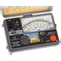
Brand : Kyoritsu
Model : KEW 8035
Category : Measurement