KEW 8130 - Measurement Kyoritsu - Free user manual and instructions
Find the device manual for free KEW 8130 Kyoritsu in PDF.

| Product Type | Clamp Meter |
| Brand | Kyoritsu |
| Model | KEW 8130 |
| Measurement Functions | AC/DC Current, AC/DC Voltage, Resistance, Continuity, Diode Test, Frequency, Capacitance, Temperature |
| Display | LCD with Backlight |
| Max AC Current | 1000A |
| Max DC Current | 1000A |
| Max AC Voltage | 1000V |
| Max DC Voltage | 1000V |
| Resistance Range | Up to 40 MΩ |
| Safety Rating | CAT IV 600V, CAT III 1000V |
| Power Supply | 2 x AAA Batteries |
| Dimensions | 254 x 82 x 36 mm |
| Weight | 310 g (approx.) |
| Storage Temperature | -20°C to 60°C |
| Operating Temperature | 0°C to 50°C |
| Humidity | 80% RH max (non-condensing) |
| Accessories Included | Test Leads, Temperature Probe, Carrying Case, Manual |
| Special Features | True RMS, Data Hold, Auto Range, Peak Hold, Max/Min, Relative Mode |
| Cleaning | Wipe with a dry cloth; do not use solvents |
| Calibration | Recommended annually |
Frequently Asked Questions - KEW 8130 Kyoritsu
User questions about KEW 8130 Kyoritsu
0 question about this device. Answer the ones you know or ask your own.
Ask a new question about this device
Download the instructions for your Measurement in PDF format for free! Find your manual KEW 8130 - Kyoritsu and take your electronic device back in hand. On this page are published all the documents necessary for the use of your device. KEW 8130 by Kyoritsu.
USER MANUAL KEW 8130 Kyoritsu
natural_image
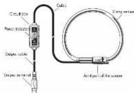
Pure electrical circuit lines without any symbolsFLEXIBLE CLAMP SENSOR
POWER CLAMP SENSOR Series
KEW 8130
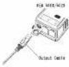
Cautions for using this clamp sensor with KEW5010/9120:
Some KEW50105020 that were manufactured before the specific timing of production may not be used with this clamp sensor. Please refer to "6-3 Connecting with Logger (KEW50105020)" and does the next run.
- SAFETY WARNINGS
This claim was not been designed and tested according to IEC61010-1; Safety Requirements for Electronic Measuring Apparatus and delivered in the case condition after passing quality control tests. This exclusion manual number warnings and safety issues which have to be observed by the user to ensure safe operation of the claims sensor and to maintain it in safe condition. Therefore, read through these operating structures below using the claims sensor.
△ DANGER
- Read through and understand instructions contained in this manual before starting in use the component
- Keep the manual at hand to enable quick reference whenever necessary.
- The comp-ware is to be used only in the manual application. - Understand and follow at the safety instructions contained in the manual.
It is expected that the above instructions are adhered to failure to follow the above instructions may cause injury, clamp damage and/or damage to equipment under test. KYORITSU is not liable for any damage resulting from the use of misrancing of the damage sensor.
The symbol △ extracted on the clamp sensor means that the user must refer to the related park in the manual for side operation of the clamp sensor. It is essential to read the instructions wherever the d symbol appears in the manual.
△ DANGER. is reserved for conditions and actions that are likely to cause serious or fatal injury. △ WARNING is reserved for conditions and actions that can be used in the main area.
△ CAUTION: is reserved for conditions and actions that can
cause injury or instrument damage. △ DANGER
- With attention to the measurement category to which the object under test bolongs, and do not make measurements on a circuit in which the electrical potential exceeds the following values: NOW for CAT IV and EREV for CAT III or lower categories.
- SPECIFICATION
| Model name: KEV190 | |
| Measurement ACC 8800A | |
| Color voltage | AC200(VA)AC100(AC,5NVA) |
| Measurement range | AC20~600(Hz/DC) |
| Accuracy | AC 70dB(A)AC 40dB(A) |
| Flow rate, r/r | AC 50dB(A) 40dB(A) |
| Phase characteristics | AC 50 dB (w/Hz) |
| AC 30 dB (w/Hz) | |
| Current consumption speed, kg/s, kW | min. 2mA |
| Temperature & humidity (°C), (mm/mm2) or (kPa) | 25°C, Relative humidity: 85% or less; 100% or less |
| Operating temperature & humidity range | 100 to 50°C, Relative humidity: 85% or less (on or above) |
| Temperature & humidity range | 20°C to 50°C, Relative humidity: 25% or less (on or above) |
| Max allowable r/r | AC100A (continuous) |
| Control temperature | 100°C or less |
| Electrical control condition | Static, gpm 2000s, inductance |
| Applicable standard | IEQ 6101-2 |
| IEQ 6101-20 | |
| IEQ 6101-20 | |
| Detachment CAT: BDN(Min)/cat, CAT: 0V(0Vmax) | |
| Pulsure degree 2 | |
| IEQ 6101-20 | |
| Growth motor components | EU 1011S drive component |
| Air intake voltage | AC50~50V, max. 600kW±5 sec. |
| Batter current - 500V DC | |
| Insulation resistance | 500A DC 100V |
| Insulation current - 500mA | |
| Motor valve conductivity, m/s | Max. 150m |
| Cycle length | Ratioscope sensor - dual circuit apumps, 2.7V |
| Doubtant circuit block - dual terminal apumps, 5.0m | |
| Control nominal | MINI SIN 00% |
| Weight | Average: 18kg |
| Accessories instruction number | Cable number: 1 (bit / D) (inch) |
| Camping curve: (MAX1.95K) | |
WARNING
- Never attempt to make any measurement if any abnormal conditions, such as a broken cover or exposed metal parts are pruned on the clamp cover.
Do not assessome, install substitute parts in mini and modification to the clamp sensor. Return the clamp sensor to your local KYORTSU distributor for repair or re-calibration in some it is affected by my own plan.
- Do not use the clamp sensor if the clamp atom or your hands are wet. Otherwise, every cat shock poodong more cool.
- Use regulated protective gear for your safety when using this component.
CAUTION
- Do not step on or push the cord; it may damage the jacket of cord. - Do not expose the clamp sensor to direct sunlight; high temperatures, humidity or heat. Otherwise, it may cause inflammation or abnormalities
- Not to give shocks, such as vibration or drop, which may damage the damping effect.
● Use a camp cloth with water in neutral detergent for cleaning the camp space. Do not use administration or safety.
This clamp sensor is not designed to be dust or waterproof. Do not use it dusty places or where the clamp sensor is likely to be
- Never catch foreign matters or give vibrations at the junction
parts of the clamp sensor. Otherwise, matching area of Jaws may be damaged and cause influences on the measurements.
- Do no, then of pull the set of the cards in order to prevent breaks in the cards. - Given that the card opening the morning paper for
- Never apply the current extending the maximum range of a long time. It may change the change sensor. - Never apply the current with the maximum range
- Hume concrete remains the conductors with conductors above are on or clamping onto the conductor under test. Otherwise, the
- Connected devices of clamp sensors may be damaged. ● Accurate measurement may not be obtained in the vicinity of
Alting the price, which is an analyst's, high-earnings credit or wicksomechanics.
Meaning of symbols on the clamp sensor
d. Use real part in the operations in the solution method for activity response.
二 Camp series who double or reinforced population
Do not apply secured or removed from unintended hazardous low conductors, which may under electric shock, electric
- bram, or unfush. \~ NC
Crossed-out school in square (according to WEEE Directive 2002/05/EC) indicating that this electrical product may not be treated as household waste, but that it must be collected and treated separately.
- OPERATING INSTRUCTIONS
t. DANSER
- All measurements of the measurement category at which the input under test belongs, and do not make measurements on a circuit in which the electrical potential exceeds the following values: ICV for CAT IV and BICV for CAT II or lower conductivity.
CAUTION
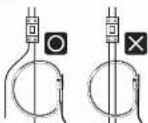
The monolateral conductor is a max. ^10 mm at constant. Accurate results were then be observed if the ramp sensor is connected directly.
- When disconnecting the output terminal from the measuring instrument, do so by removing the plug first and not by pulling the card.
6-1 Measuring method
(1) Connect the output terminal to the input terminal on the measuring procurement
[2] Poen of the research department
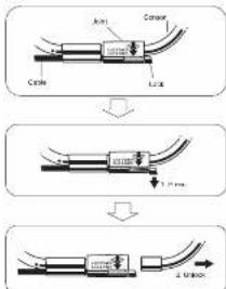
(3) Press the Joint according to the following illustrations and unlock it.
flowchart
graph TD
    A["Line 1"] --> B["Step 1: Cable"]
    B --> C["Step 2: Cable"]
    C --> D["Step 3: Cable"]
    D --> E["Final Cable"]
Measurement Category:
To ensure safe operation of measuring instruments, IEC 61010 establishes safety standards for various electrical environments categorized as O in CAT IV, and codes measured categories. Higher-numbered categories conceptual to check environmental with greater momentary energy, so a measuring instrument designed for CAT III environments can ensure greater momentary energy than one designed for CAT II.
O : Circuits which are not directly connected to the mains
power supply
CAT II Electrical circuits of equipment technicians to an AC electrical outlet by a power cord.
II: Primary electrical circuits of
directly to the distribution panel and barriers from the
distribution panel to cutels.
CAT IV: The circuit from the service drop to the service entrance and to the power meter and primary control current protection device (diastalized unit).
- FEATURES
● This is a Clamp Sensor capable of measuring AG current up to 1000A.
● Flexible and light weight because of an air core coil used at the Clamp Sensor part
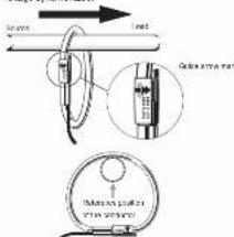
[4] Clamp lens wire conductor under the load, enables the remainder to the source an unknown in the below line. When connecting the Clamp sensor with our Power motor (MODEL6316 etc.) check the direction of the Outer screw mark indicating that current flow direction marked on the drain of the Clamp sensor to make the phase of the current under load and output voltage synchronized.
Reference and production of the manufacturer
(5) Confirm that the Joint on the Clamp sensor is firmly locked.
● juried part of the Clamp sensor may be disconnected from the known device.
- Clamp onto one conductor only: measurements cannot be made when clamping single phase (2-wire) or three-phase (3-wire) at the source time.
- CLAMP SENSOR LAYOUT
- PIN ASSIGNMENT FOR OUTPUT TERMINAL
The air assignment for the subject, terminal of the clone sensor is an release.
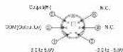
* Pn assignment at the correcting terminal of measuring instrument is symmetrical to above figure.
- Output signal passes between 3 and 6 of Output terminal. - This clamp sensor is supplied power via an Output cable. Power supply of 12.0 to 15.5V is required between 1 and 3 of Output terminal and -3.0 to -5.5V are required between 2 and 3 of Output terminal.
6-2 Connecting with Power meter (KEYW315|KEW8310|KEW8305 MODEL8300)
When this clamp sensor is detected by the auto detection function of our KENW8130-6375. However, made after the correction, the type of the clamp sensor and the displayed no indicators. On KENW8130, the displayed model name will not be "KEW8130", however, this is not a malfunction. Enter the model name according to the following label it retires the type of the clamp sensor directly.
Power source Model name connected through the auto detection function KEW610 MODEL9-24 KEWK15 MODEL 8124810
● MODEL63001 KEY/5805 does not correct the connected clamp sensors automatically. Enter the model name directly: MODEL63001
- In the detailed setting of the clump sensor, please refer to the instruction manual for each Power motor.
6-3 Connecting with Logger (KEW50105020)
When using this clamp sensor together with our KLOK210 (5000
(1) Connect the same sensor to CHI of KEN5018 5020 while KEN5016 / 5020 is in scanned off status.
(2) Then power on KEW5010 5020. Time will be displayed, and then 130 and "1900A" will be displayed. (KEW5010 5020 checks the connected clamp sensors when it is
displays the clamp sensor type and a proper range automatically.)
(3) Now the instrument is ready for measurements. When DQ^* (no connection) is displayed on the LCD; it means no clamp sensor is connected to the selected channel or the connection is close.
In this case, check the connection and reconnect the clamp source and power at REWS010-15020. Then sensor I can open
* Only KEM5010 / 6020 which have the following or later serial number may be used with the clamp sensor. KEV5010: No 8021568 or new KEV5020: No 8020762 or new
- 11.01