
8125 - Measurement Kyoritsu - Free user manual and instructions
Find the device manual for free 8125 Kyoritsu in PDF.


| Product Type | AC/DC Clamp Meter |
| Brand | Kyoritsu |
| Model | 8125 |
| Category | Measurement |
| Dimensions (approx.) | 230 x 70 x 38 mm |
| Weight (approx.) | 220 g (including batteries) |
| Power Supply | 2 x AAA batteries (1.5V) |
| AC Current Range | 0 to 200 A (with resolution 0.1 A) |
| DC Current Range | 0 to 200 A (with resolution 0.1 A) |
| AC Voltage Range | 0 to 600 V (with resolution 0.1 V) |
| DC Voltage Range | 0 to 600 V (with resolution 0.1 V) |
| Resistance Range | 0 to 20 MΩ (with auto-ranging) |
| Frequency Measurement | Yes, up to 1 kHz |
| Continuity Test | Yes (with buzzer) |
| Diode Test | Yes |
| Data Hold | Yes |
| Auto Power Off | Yes (approx. 15 minutes) |
| Safety Rating | CAT III 600V, CAT II 1000V |
| Accessories Included | Test leads, batteries, carrying case, manual |
| Maintenance | Clean with a dry, soft cloth. Do not use solvents. |
| Spare Parts Availability | Test leads and batteries are replaceable. |
Frequently Asked Questions - 8125 Kyoritsu
User questions about 8125 Kyoritsu
0 question about this device. Answer the ones you know or ask your own.
Ask a new question about this device
Download the instructions for your Measurement in PDF format for free! Find your manual 8125 - Kyoritsu and take your electronic device back in hand. On this page are published all the documents necessary for the use of your device. 8125 by Kyoritsu.
USER MANUAL 8125 Kyoritsu
POWER CLAMP SENSOR Series
MODEL 8124/8125/8126/8127

KYORITSU ELECTRICAL INSTRUMENTS WORKS, LTD.,
TOKYO, JAPAN
DISTRIBUTOR

KYORITSU ELECTRICAL
INSTRUMENTS
WORKS, LTD.
2-5-20, Nakane, Meguro-ku,
Tokyo: 152-0031 Japan Phone: +81-3-3723-0131
Fax: +81-3-3723-0152
Factory: Ehime, Japan
www.kew-Itd.co.jp
5-22
92-1640E
1. Safety warnings
This instrument has been designed, manufactured and tested according to 6800: Safety requirements for Electronic Measuring apparatus, and delivered in the best condition after passing quality control tests. This instruction manual contains warnings and safety rules which have to be observed by the user to ensure operation of the instrument and to maintain it in safe condition. Therefore, read through these operating instructions before using the instrument.
WARNING
● Read through and understand instructions contained
in this manual before using the instrument.
- Keep the manual at hand to enable quick reference whenever necessary.
● The instrument is to be used only in its intended
applications.
The operating instructions described in the manual must be observed.
● Understand and follow all the safety instructions
contained in the manual.It is essential that the above
instructions are adhered to. Failure to follow the above instructions may cause injury and or instrument
above instructions may cause injury and of instrument damage. Kyoritsu is by no means liable for any
damage resulting from the instrument in contradiction
to this cautionary note.
The symbol indicated on the instrument, means that
the user must refer to the related parts in the manual for safe operation of the instrument. It is essential to read the
sale operation of the instrument. It is essential to read the instructions wherever the △ symbol appears in the
instructions inside the symbol exposure in the manual.
△ DANGER is reserved for conditions and actions
that are likely to cause serious or fatal
⚠ WARNING is reserved for conditions and actions
that can cause serious or fatal Injury.
△ CAUTION is reserved for conditions and actions that can save minor injury or
that can cause minor injury of instrument damage
△ DANGER
● Never make measurement on a circuit in which the electrical potential exceeds AC 300V using MODEL8127 and A600V using MODEL124, 8125 and 8126.
- Do not make measurement when thunder rumbling. If the instrument is in use, stop the measurement immediately and remove the instrument from the safe measured object.
- Do not attempt to make measurement in the presence of flammable gasses. Otherwise, the use of the instrument may cause sparking, which can lead to an explosion.
● The transformer jaws are made of metal tips are not completely insulated. Be especially careful about the possible shorting where the measured object has exposed metal parts.
- Never attempt to use the instrument if it's surface or
your hand are wet. Do not exceed the maximum allowable
- Do not exceed the maximum allowable measuring range.
WARNING
● Never attempt to make any measurement, if any
abnormal conditions are noted, such as broken
● Do not install substitute parts or make any
● Do not install substitute parts of make any modification to the instrument. Return the
to the distributor from who you purchased this instrument for repair or re calibration in case of
instrument for repair of re-cambration in case of suspected faulty operation.
● Always keep your fingers and hands behind the barrie
on the instrument to avoid the possible shock hazard.
CAUTION
● Do not step on or pinch the cord to prevent the jacket of cord from being damaged.
● The output connector shall be removed or connect
without clamping a conductor. Otherwise, it may
cause a failure. ● Do not expose the instrument to direct run
- Do not expose the instrument to direct salt temperatures, humidity or dew.
● Never give shocks, such as vibration or
may damage the instrument. ● Use a damp cloth and detergent for cleaning the
- Use a damp cloth and detergent for cleaning the instrument. Do not use abrasives or solvents.
Safety symbols
| Refer to the instructions in the manual. | |
| Indicates a Instrument with double or reinforced insulation | |
| Indicates that this instrument can clamp on bare conductors. | |
| Indicates AC |
○ Measurement Category
To ensure safe operation of measuring instruments, IEC 61010 establishes safety standards for various electrical environments, categorized as 0 to CAT IV, and called measurement categories. Higher-numbered categories correspond to electrical environments with greater momentary energy, so a measuring instrument designed for CAT III environments can endure greater momentary energy out of any than one designed for CAT II.
Circuits which are not directly connected to the
mains power supply
case, CAT II : Electrical circuits of equipment connected to an AC
electrical outlet by a power cord.
CAT III: Primary electrical circuits of the equipment instrument connected directly to the distribution panel
CAT IV: The circuit from the service drop to the service entrance, and to the power meter and primary overcurrent protection device (distribution panel).

2. Features
●This is a clamp sensor for our Power meter. ●Designed to international safety standard IEC61010-2-032 CAT III Pollution Degree 2
- Instrument layout

Barrier: It is a part providing protection against electrical shock and ensuring the minimum required air and creepage distances.
- Din plug pin assignment

3: GND pin 5: Output signal pin 1, 2, 4 and 6: No use
* Above figure shows the pin assignment seeing Clamp sensor from output connector part. The figure of the pin assignment of connection terminal is symmetrical to above figure.
6. Operating instructions
DANGER
● Never make measurement on a circuit in which the electrical potential exceeds 300V using MODE127 and AC600V using MODEL8124, 8125 and 8126 in order to avoid possible shock hazard.
The transformer jaws are made of metal a are not completely insulated. Be especially careful about the possible shorting where the measured object has exposed metal parts.
CAUTION
● Take sufficient care to avoid shock, vibration of excessive force when handling the instrument. Otherwise, precisely adjusted transformer jaws damaged.
- When transformer jaws do not fully close, close them by force, but make them free to try again. If a foreign substance is stuck tips, remove it.
● When making current measurements, keep the
Otherwise accurate measurements cannot be taken
Otherwise, accurate measurements cannot be taken. Maximum conductor size is as follows. MODEL8124 : 68mm in diameter MODEL8125/ 8126: 40mm in diameter MODEL8127 : 24mm in diameter
- Hold the inserting part (except for the cable) and disconnect the Output connector from the measuring instrument so as not to cause a break in the cord.
their tips
tips
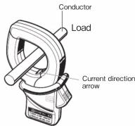
mark (Power source to load), which is indicated on the transformer jaws, with the current flowing direction order to synchronize the phases of measured current and output voltage. Ensure that the tips of transformer jaws are firml closed.
6.2 Setting for Power meter
When using any of these sensors 6005 KEW 6315, please refer to the instruction manual, eit which you're using, and carefully check sensor settings and available current ranges.
6-1 Measurement procedures
(1) Connect the Output connector to the Input terminal of
(2) Press the Trigger to open the transformer jaws and
clamp onto one conductor. In this case, the measured conductor shall be at the center of the jaws. When connecting a sensor with a Power meter (our Power meter, MODB300, etc.) match the arrow

This instrument satisfies the marking requirement defined in the WEEE Directive (2002/96/EC). This symbol indicates separate collection for electrical and electronic equipment.
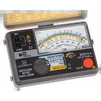
Brand : Kyoritsu
Model : 8125
Category : Measurement