
WM101MV2 - Microphone Eikon - Free user manual and instructions
Find the device manual for free WM101MV2 Eikon in PDF.

User questions about WM101MV2 Eikon
0 question about this device. Answer the ones you know or ask your own.
Ask a new question about this device
Download the instructions for your Microphone in PDF format for free! Find your manual WM101MV2 - Eikon and take your electronic device back in hand. On this page are published all the documents necessary for the use of your device. WM101MV2 by Eikon.
USER MANUAL WM101MV2 Eikon
Wireless Microphone System
USER'S MANUAL
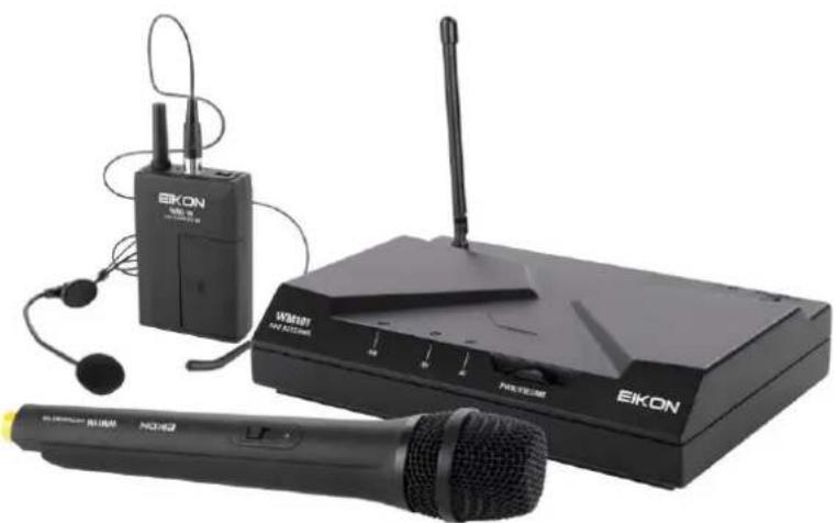
natural_image
Black electronic device setup including EIKON audio and wireless router, with earphones and microphone (no visible text or symbols)ITALIANO
ENGLISH
DISPOSAL OF OLD ELECTRICAL & ELECTRONIC EQUIPMENT....3
SAFETY INSTRUCTIONS....3
IN CASE OF FAULT....3
PACKAGING, SHIPPING AND COMPLAINT ....4
WARRANTY AND PRODUCTS RETURN 4
MAINTENANCE AND DISCLAIMER....4
POWER SUPPLY....4
USER'S WARNINGS AND CE CONFORMITY....5
INTRODUCTION 6
DESCRIPTION 6
WM101 RECEIVER....6
WM11M HANDHELD TRANSMITTER 7
WM11B BODYPACK TRANSMITTER....7
TECHNICAL SPECIFICATION....8
DISPOSAL OF OLD ELECTRICAL & ELECTRONIC EQUIPMENT

This marking shown on the product or its literature, indicates that it should not be disposed with other household wastes at the end of its working life. To prevent possible harm to the environment or human health from uncontrolled waste disposal, please separate this from other types of wastes and recycle it responsibly to promote the sustainable reuse of material resources. Household users should contact either the retailer where they purchased this product, or their
local government office, for details of where and how they can take this item for environmentally safe recycling. Business users should contact their supplier and check the terms and conditions of the purchase contract. This product should not be mixed with other commercial wastes for disposal.
SAFETY INSTRUCTIONS
- CAUTION - Before using this product read carefully the following safety instructions. Take a look of this manual entirely and preserve it for future reference. When using any electric product, basic precautions should always be taken, including the following:
- To reduce the risk, close supervision is necessary when the product is used near children.
- Protect the apparatus from atmospheric agents and keep it away from water, rain and high humidity places.
- This product should be site away from heat sources such as radiators, lamps and any other device that generate heat.
- Care should be taken so that objects and liquids do not go inside the product.
- The product should be connected to a power supply only of the type described on the operating instructions or as marked on the product.
IN CASE OF FAULT
- In case of fault or maintenance this product should be inspected only by qualified service personnel when:
■ Liquids have spilled inside the product.
■ The product has fallen and been damaged.
The product does not appear to operate normally or exhibits a marked change in performance.
- Do not operate on the product, it has no user-serviceable parts inside.
- Refer servicing to an authorized maintenance centre.
PACKAGING, SHIPPING AND COMPLAINT
- This unit package has been submitted to ISTA 1A integrity tests. We suggest you control the unit conditions immediately after unpacking it.
- If any damage is found, immediately advise the dealer. Keep all unit packaging parts to allow inspection.
• Proel is not responsible for any damage that occurs during shipment. - Products are sold "delivered ex warehouse" and shipment is at charge and risk of the buyer.
- Possible damages to unit should be immediately notified to forwarder. Each complaint for manumitted package should be done within eight days from product receipt.
WARRANTY AND PRODUCTS RETURN
• Proel products have operating warranty and comply their specifications, as stated by manufacturer.
- Proel warrants all materials, workmanship and proper operation of this product for a period of two years from the original date of purchase. If any defects are found in the materials or workmanship or if the product fails to function properly during the applicable warranty period, the owner should inform about these defects the dealer or the distributor, providing receipt or invoice of date of purchase and defect detailed description. This warranty does not extend to damage resulting from improper installation, misuse, neglect or abuse. Proel S.p.A. will verify damage on returned units, and when the unit has been properly used and warranty is still valid, then the unit will be replaced or repaired. Proel S.p.A. is not responsible for any "direct damage" or "indirect damage" caused by product defectiveness.
MAINTENANCE AND DISCLAIMER
- Clean only with dry cloth.
- Proel products have been expressly designed for audio application, with signals in audio range (20Hz to 20kHz). Proel has no liability for damages caused in case of lack of maintenance, modifications, improper use or improper installation non-applying safety instructions.
• Proel S.p.A. reserves the right to change these specifications at any time without notice. - Proel S.p.A. declines any liability for damages to objects or persons caused by lacks of maintenance, improper use, installation not performed with safety precautions and at the state of the art.
POWER SUPPLY
- This apparatus should only be connected to power source type specified in this owner's manual or on the unit.
- If the supplied AC power cable plug is different from the wall socket, please contact an electrician to change the AC power plug.
- Hold the plug and the wall outlet while disconnecting the unit from AC power.
- If the unit will not be used for a long period of time, please unplug the power cord from AC power outlet.
- To avoid unit power cord damage, please do not strain the AC power cable and do not bundle it.
- In order to avoid unit power cord damage, please ensure that the power cord is not stepped on or pinched by heavy objects.
USER'S WARNINGS AND CE CONFORMITY
- LICENSING INFORMATION: This radio equipment operates in the 863-865 MHz harmonized European band dedicated to SRD (short range devices) like wireless microphone and IEM personal monitor systems, so in the countries specified in the below table no personal license is required for use it.
- The use of this wireless microphone equipment in some countries could be intended for professional use, so the licensability depends on the country it operates. Proel suggests the user to contact the appropriate telecommunications authority concerning proper licensing.
- This equipment may be capable of operating on some frequencies not authorized in your country. Please contact your national authority to obtain information on authorized frequencies for wireless microphone products in your region.
• The product is in compliance with 2014 / 30/ EU EMC Directive & 2014 /35 / EU LVD Directive. - PROEL S.p.A hereby, declares that this wireless microphone system complies with the essential requirements of Radio Equipment Directive (RED) 2014 / 53 / EU.
- The full and detailed declaration of conformity can be downloaded from the web site: www.Eikon-audio.com
| TABLE OF THE AUTHORIZED FREQUENCIES FOR THE WM101 WIRELESS MICROPHONE SYSTEM IN EUROPE UPDATED WITH REFERENCE TO ERC-REC 70-03E DOCUMENT DATED FEBRUARY 7 2014 | ||||||
| COUNTRY CODE | WM11M / WM11B TRANSMITTING FREQUENCIES | |||||
| 863.100 | 863.900 | 864.850 | ||||
| AT BE CY CZ DK EE DE GR HU IT LV LT LU NL PL PT SK SI SE GB IS LI CH BG RO TR UA IE MT NO ES FR | ● | ● | ● | |||
| HR | Individual license required | |||||
| GE RU | NOT IMPLEMENTED | |||||
| IN ALL COUNTRIES THE USE OF WIRELESS MICROPHONES SYSTEMS IS SUBJECT TO ANY TELEVISION AND BROADCAST TRANSMISSION | ||||||
| CONSULT LOCAL OR NATIONAL RADIO SPECTRUM AUTHORITIES FOR INFORMATION ON POSSIBLE RESTRICTIONS OR NECESSARY AUTHORIZATIONS BEFORE USING THIS SHORT RANGE DEVICE. | ||||||
INTRODUCTION
Thank you for choosing this PROEL product and for your trust in our brand, synonymous of professionalism, accuracy, high quality and reliability. All our products are CE approved and designed for continuous use in professional systems.
DESCRIPTION
The WM101 Wireless Microphones series is a UHF, quartz controlled, fixed frequency device, which provides a reliable, high quality signal transmission.
WM101 Wireless Microphone system features 3 units: WM101 receiver, WM11M handheld transmitter and WM11B body pack transmitter. The system is available in three different configurations, each of them including an ABS carrying case:
Three factory pre-build frequencies are available, which have been selected to allow the simultaneous use of 3 devices without interference between them (depending on the circumstances):
- 863.100 MHz
- 864.900 MHz
- 864.850 MHz
WM101 RECEIVER
See FIG. 1 at page 15:
- DC IN
Socket for the AC/DC adaptor connection, use only the adaptor supplied with the system. -
AUDIO OUT (UNBALANCED)
Unbalanced audio output with line level: connect it through a mono 6.3mm jack cable to a mixer input. -
PWR / VOLUME
On/off switch and volume potentiometer: set this control to a proper level that doesn't saturate the mixer input channel.
- ON
Red LED: if lighted states that the power supply is present and the receiver is turned on.
- RF
Green LED: if lighted states that the transmitter is sending a radio signal to the receiver.
- AF
Yellow LED: illuminates when an audio signal is present.
- ANTENNA
This is the receiving antennas. Raise it up during the use and, to obtain a better reception, place the receiver away from other metal objects and no more distant than 25m from the transmitter.
- RECEIVING FREQUENCY
In this label, together with the general data of the receiver, you can find the receiving radio frequency. In case of use of more radio apparatus it must correspond to the frequency of the wireless transmitter that will be used.
WM11M HANDHELD TRANSMITTER
See FIG. 2 at page 16:
1. MICROPHONE GRID
The grid protects the microphone capsule and include a pop filter. Type of microphone capsule is dynamic with a cardioid unidirectional figure.
2. BATT
Red LED that shows the battery status:
- When the microphone is switched on, the red led will light.
- The led will light off if the microphone is switched on, the batteries are near to be exhaust, to indicate that they must be replaced as soon as possible.
3. ON / MUTE / OFF
On/off switch, downward the microphone is off, upward the microphone is on. There is a middle position where the microphone is on but it is muted, useful in case you don't want to hear the typical switching on/off click.
4. BATTERIES COVER
Sliding down the lower part of the microphone body you can access to the battery inlet.
5. BATTERIES INLET
To operate the microphone needs 2 type AA alkaline batteries.
Note: the microphone is able to operate also with 2 Ni-MH rechargeable batteries, but in this case the operating time is less.
6. FREQUENCY
On the back side of the batteries inlet an adhesive shows the operating frequency of the transmitter.
(The figure shows some optional accessories available from the PROEL catalogue.)
WM11B BODYPACK TRANSMITTER
See FIG. 3 at page 17:
1. INPUT
TA3M mini XLR input socket to connect the supplied microphones.
2. BATTERY STATUS
Red LED that shows the battery status:
- When the microphone is switched on the red led will light.
- The led will light off if the microphone is switched on and the batteries are near to be exhaust, to indicate that they must be replaced as soon as possible.
3. OFF ON
On/off switch, fully at left the microphone is on, fully at right the microphone is off.
4. ANTENNA
This is the transmitting integral antenna: do not force, try to disconnect, or replace with other one.
5. BATTERIES COVER
Sliding down the lower part of the bodypack you can access to the battery inlet.
6. BATTERIES INLET
To operate the microphone needs 2 type AA alkaline batteries.
Note: the microphone is able to operate also with 2 Ni-MH rechargeable batteries, but in this case the operating time is less.
7. GAIN
Using a PH1 Phillips screwdriver and rotating this trimmer is possible to optimize the gain of the microphone before its signal is transmitted. Rotate it clockwise if you want an higher gain (speaking) or rotate it counter-clockwise if you want a lower gain (singing).
8. CLIP
Clip to hook the Bodypack to the belt.
9. FREQUENCY
On the back side of bodypack an adhesive shows the operating frequency of the transmitter.
TECHNICAL SPECIFICATION
| WM101 – Receiver | Modulation Method | PCM Digital 24 bit | ||
| Receiver Type | UHF Band | Spurious Emission | under limits EN 300422 | |
| Frequency Range | 863-865 MHz | Frequency Response | 50 – 15000 Hz | |
| RF Frequency Stability | ±0.002 % | Mic Capsule | Dynamic | |
| RF Image/Spurious Rej. | >70 dB | Mic Polar Pattern | Cardioid | |
| RF Interference Reject. | >70 dB | Power Requirement | 2x1.5V AA type | |
| RF Sensibility | -105 dBm | Battery Life | Up to 8 hours | |
| Frequency Response | 50 – 15000 Hz | Dimensions | 260 x ∅45 mm | |
| Modulation Method | PCM Digital 24 bit | |||
| THD Distortion | < 1% | WM11B – Bodypack Transmitter | ||
| Dynamic Range | >90 dB | Carrier Frequency Range | UHF: 863-865 MHz | |
| S/N Ratio | >100 dB | Modulation method | FM (F3E) | |
| Power Requirement | 12 V DC / 500 mA | Transmitting Power | <10 dBm Max ERP | |
| Output Connector | Unbalanced 1⁄4 “ jack | Transmission Distance | Up to 25 m (Open Space) | |
| Dimensions | H 45 x L 150 x W 118 mm | RF Frequency Stability | ±0.002 % | |
| RF Max deviation | ±50 KHz | |||
| Modulation Method | PCM Digital 24 bit | |||
| WM11M – Handheld Transmitter | Spurious Emission | under limits EN 300422 | ||
| Carrier Frequency Range | UHF: 863-865 MHz | Frequency Response | 50 – 15000 Hz | |
| Modulation method | FM (F3E) | HCM25 Mic Capsule Headset | Back electret condenser | |
| Transmitting Power | < 10 dBm Max ERP | Polar Pattern | Cardioid | |
| Transmission Distance | Up to 25 m (Open Space) | Power Requirement | 2x1.5V AA type | |
| RF Frequency Stability | ±0.002 % | Battery Life | Up to 8 hours | |
| RF Max deviation | ±50 KHz | Dimensions | H 95 x L 65 x W 23 mm | |
 | Connector Pin AssignmentsPin 1: Tied to GroundPin 2: Tied to AudioPin 3: Tied to Bias (+5V) | |||
TRATTAMENTO DEL DISPOSITIVO ELETTRICO OD ELETTRONICO A FINE VITA....9
AVVERTENZE PER LA SICUREZZA....9
IN CASO DI GUASTO....9
IMBALLAGGIO, TRASPORTO E RECLAMI....10
GARANZIE E RESI.... 10
Connections and cables
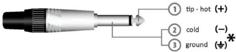
Jack (unbalanced)
*note: connect both cold and ground to make cable from balanced to unbalanced
Jack (sbilanciato)
Jack (balanced)
Jack (bilanciato)
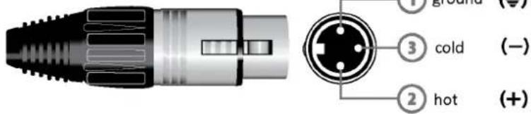
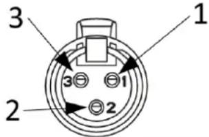
Balanced female XLR
Balanced male XLR
(World Headquarters - Factory)
- Wireless Microphone System
- USER'S MANUAL
- DISPOSAL OF OLD ELECTRICAL & ELECTRONIC EQUIPMENT
- SAFETY INSTRUCTIONS
- IN CASE OF FAULT
- PACKAGING, SHIPPING AND COMPLAINT
- WARRANTY AND PRODUCTS RETURN
- MAINTENANCE AND DISCLAIMER
- POWER SUPPLY
- USER'S WARNINGS AND CE CONFORMITY
- INTRODUCTION
- DESCRIPTION
- WM101 RECEIVER
- WM11M HANDHELD TRANSMITTER
- MICROPHONE GRID
- BATT
- ON / MUTE / OFF
- BATTERIES COVER
- BATTERIES INLET
- FREQUENCY
- WM11B BODYPACK TRANSMITTER
- INPUT
- BATTERY STATUS
- OFF ON
- ANTENNA
- BATTERIES COVER
- BATTERIES INLET
- GAIN
- CLIP
- FREQUENCY
- Connections and cables
Brand : Eikon
Model : WM101MV2
Category : Microphone