USER MANUAL CSTZ50TKEW PANASONIC
Operating Instructions
Air Conditioner
text_image
Panasonic
Model No.
Indoor Unit
CS-TE20TKEW
CS-TE25TKEW
CS-TE35TKEW
CS-TE42TKEW
CS-TE50TKEW
CS-TE60TKEW
CS-TZ20TKEW
CS-TZ25TKEW
CS-TZ35TKEW
CS-TZ42TKEW
CS-TZ50TKEW
CS-TZ60TKEW
CS-TZ71TKEW
CS-MTZ16TKE
Outdoor Unit
Single Split (R410A)
CU-TE20TKE
CU-TE25TKE
CU-TE35TKE
CU-TE42TKE
CU-TE50TKE
CU-TE60TKE
Single Split (R32)
CU-TZ20TKE
CU-TZ25TKE
CU-TZ35TKE
CU-TZ42TKE
CU-TZ50TKE
CU-TZ60TKE
CU-TZ71TKE
Outdoor Unit
Multi Split (R410A)
CU-3E18PBE
CU-4E23PBE
CU-4E27PBE
CU-5E34PBE
CU-2E12SBE
CU-2E15SBE
CU-2E18SBE
CU-3E23SBE
CU-2RE15SBE
CU-2RE18SBE
CU-3RE18SBE
Multi Split (R32)
CU-2Z35TBE
CU-2Z41TBE
CU-2Z50TBE
CU-3Z52TBE
CU-3Z68TBE
CU-4Z68TBE
CU-4Z80TBE
CU-5Z90TBE
CU-2TZ41TBE
CU-2TZ50TBE
CU-3TZ52TBE
Operating Instructions
2-15
Air Conditioner
Before operating the unit, please read these operating instructions thoroughly and keep them for future reference. The included Installation Instructions should be kept and read by the installer before installation.
Remote control is packaged in the indoor unit and removed by the installer before installation.
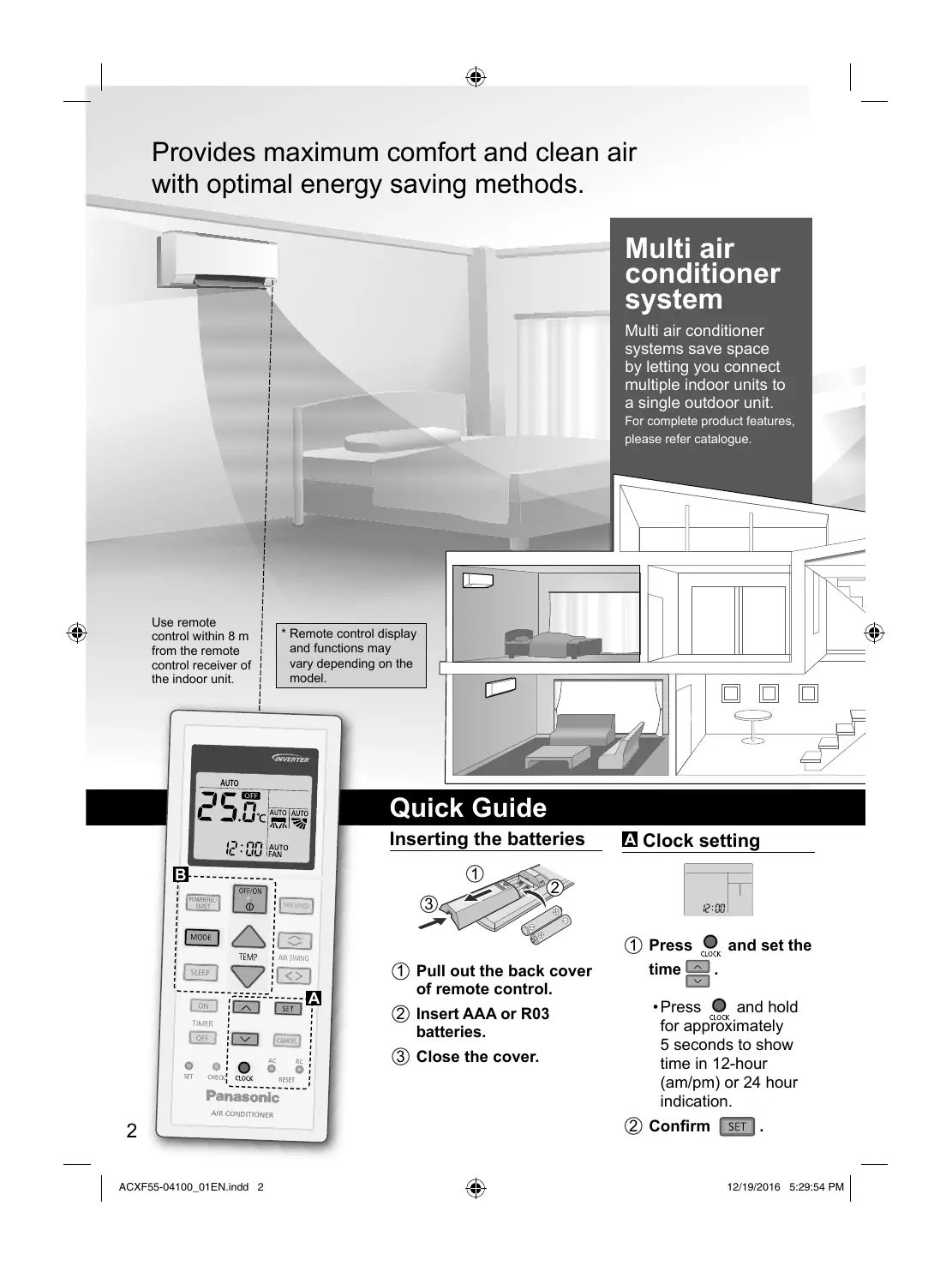
Provides maximum comfort and clean air with optimal energy saving methods.
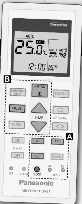
Use remote control within 8 m from the remote control receiver of the indoor unit.
text_image
INVERTER
AUTO
25.0°C
12:00
AUTO
AUTO
FAN
POWERFUL/
QUIET
OFF/ON
FAN SPEED
MODE
TEMP
AIR SWING
SLEEP
ON
SET
TIMER
OFF
CANCEL
SET CHECK
CLOCK
AC RC
RESET
Panasonic
AIR CONDITIONER
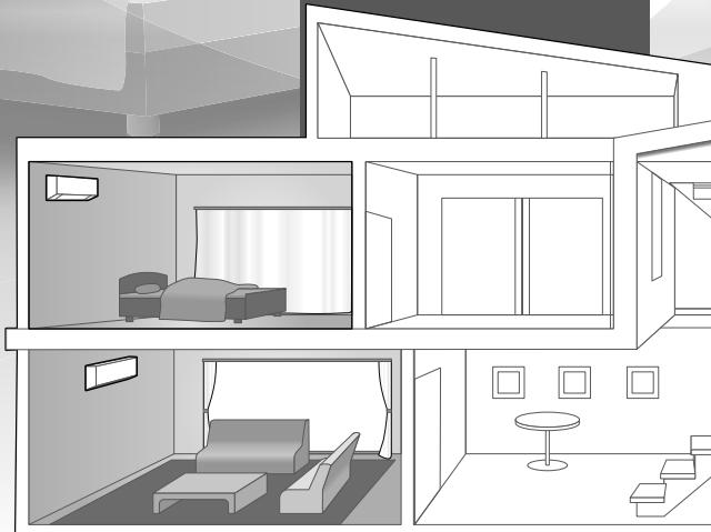
Multi air conditioner system
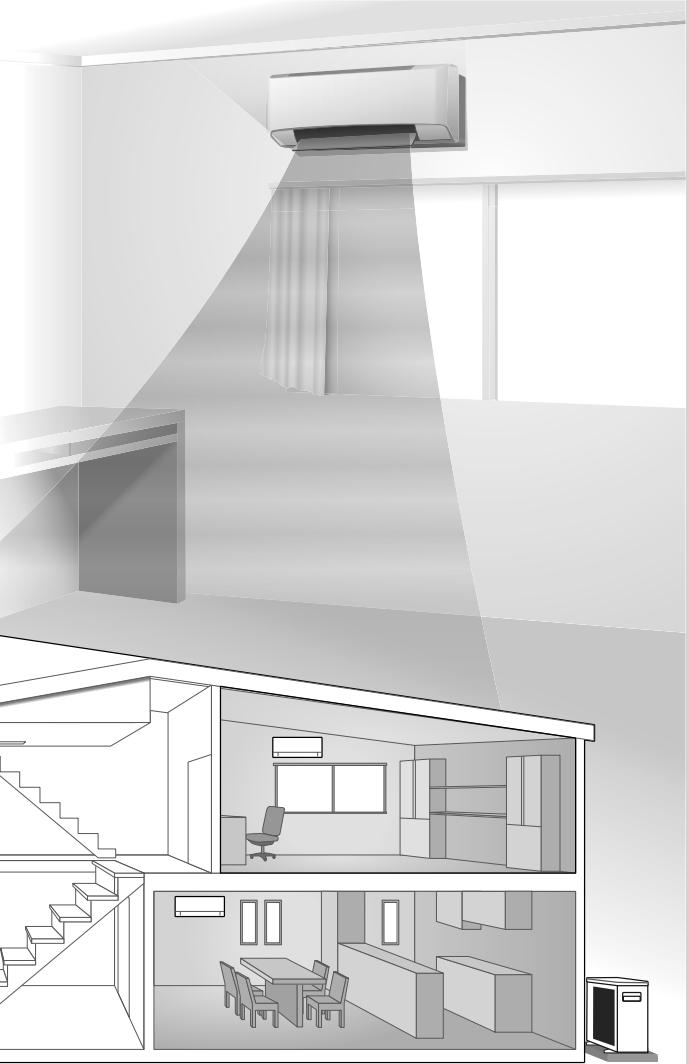
Multi air conditioner systems save space by letting you connect multiple indoor units to a single outdoor unit. For complete product features, please refer catalogue.
natural_image
Architectural line drawing of a modern living room interior with furniture and furniture layout (no text or symbols)
Quick Guide
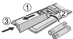
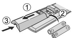
Inserting the batteries
text_image
Diagram showing three labeled components of a battery pack assembly with arrows indicating direction
① Pull out the back cover of remote control.
② Insert AAA or R03 batteries.
③ Close the cover.
A Clock setting
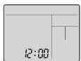
① Press CLOCK and set the time ^.
- Press _CLOCK and hold for approximately 5 seconds to show time in 12-hour (am/pm) or 24 hour indication.
② Confirm SET .
natural_image
Interior architectural rendering of a modern room with staircase, staircase, and ceiling air conditioner (no text or symbols)
Thank you for purchasing Panasonic Air Conditioner.
Table of contents
Safety precautions...... 4-7
How to use...... 8-9
To learn more...... 10-11
Cleaning instructions...... 12
Troubleshooting...... 13-15
Information...... 86
Accessories
- Remote control
- AAA or R03 batteries × 2
- Remote control holder
- Screws for remote control holder × 2
The illustrations in this manual are for explanation purposes only and may differ from the actual unit. They are subject to change without notice for future improvement.
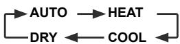
B Basic operation
① Press MODE to select the desired mode.
② Press OFF/ON to start/
① stop the operation.
- Please note that the OFF indication is on display to start the unit.
③ Select the desired temperature.
Selection range:
16.0 °C \~ 30.0 °C /
60 °F \~ 86 °F.
- Press and hold ▼ for approximately 10 seconds to switch the temperature indication in °C or °F.
Safety precautions
To prevent personal injury, injury to others or property damage, please comply with the following:
Incorrect operation due to failure to follow instructions below may cause harm or damage, the seriousness of which is classified as below:
This appliance is not intended for accessibility by the general public.

For appliance filled with R32 (mild flammable refrigerant). If the refrigerant is leaked and exposed to an external ignition source, there is a risk of fire.

WARNING
This sign warns of death or serious injury.

CAUTION
This sign warns of injury or damage to property.
The instructions to be followed are classified by the following symbols:

This symbol denotes an action that is PROHIBITED.


These symbols denote actions COMPULSORY.
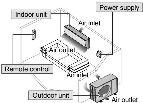
flowchart
graph TD
    A["Air inlet"] --> B["Air outlet"]
    B --> C["Outdoor unit"]
    C --> D["Air outlet"]
    D --> E["Power supply"]
    F["Indoor unit"] --> B
    G["Remote control"] --> B
    H["Outdoor unit"] --> D

WARNING
Indoor unit and outdoor unit

This appliance can be used by children aged from 8 years and above and persons with reduced physical, sensory or mental capabilities or lack of experience and knowledge if they have been given supervision or instruction concerning use of the appliance in a safe way and understand the hazards involved. Children shall not play with the appliance. Cleaning and user maintenance shall not be made by children without supervision.
Please consult authorised dealer or specialist to clean the internal parts, repair, install, remove and reinstall the unit. Improper installation and handling will cause leakage, electric shock or fire.
Confirm with authorised dealer or specialist on usage of any specified refrigerant type. Using refrigerant type other than the specified may cause product damage, burst and injury etc.

Do not install the unit in a potentially explosive or flammable atmosphere. Failure to do so could result in fire.
Do not insert your fingers or other objects into the air conditioner indoor or outdoor unit, rotating parts may cause injury.

Do not touch the outdoor unit during lightning, it may cause electric shock.

Do not expose yourself directly to cold air for a long period to avoid excess cooling.
Do not sit or step on the unit, you may fall down accidentally.

Remote control

Do not allow infants and small children to play with the remote control to prevent them from accidentally swallowing the batteries.
Power supply

Do not use a modified cord, joint cord, extension cord or unspecified cord to prevent overheating and fire.


To prevent overheating, fire or electric shock:
- Do not share the same power outlet with other equipment.
- Do not operate with wet hands.
- Do not over bend the power supply cord.
- Do not operate or stop the unit by inserting or pulling out the power plug.

If the supply cord is damaged, it must be replaced by the manufacturer, service agent or similarly qualified persons in order to avoid a hazard.
It is strongly recommended to be installed with Earth Leakage Circuit Breaker (ELCB) or Residual Current Device (RCD) to prevent electric shock or fire.
To prevent overheating, fire or electric shock:
- Insert the power plug properly.
- Dust on the power plug should be periodically wiped with a dry cloth.
Stop using the product if any abnormality/failure occurs and disconnect the power plug or turn off the power switch and breaker.
(Risk of smoke/fire/electric shock)
Examples of abnormality/failure
• The ÉLCB trips frequently.
- Burning smell is observed.
- Abnormal noise or vibration of the unit is observed.
• Water leaks from the indoor unit.
- Power cord or plug becomes abnormally hot.
- Fan speed cannot be controlled.
• The unit stops running immediately even if it is switched on for operation.
• The fan does not stop even if the operation is stopped. Contact your local dealer immediately for maintenance/repair.

This equipment must be earthed to prevent electrical shock or fire.

Prevent electric shock by switching off the power supply and unplug:

-Before cleaning or servicing,
-When extended non-use, or
-During abnormally strong lightning activity.

WARNING
Precaution for appliance filled with R32
Pay careful attention to the following points when operating the appliances and dealing with different refrigerants.

The appliance shall be installed, and/or operated in a room with floor area larger than Amin (m²) and keep away from ignition sources, such as heat/sparks/open flame or hazardous areas such as gas appliances, gas cooking, reticulated gas supply systems or electric cooking appliances, etc. (Refer to Table A of Installation instructions table for Amin (m²))
Be aware that refrigerant may not contain an odour, highly recommended to ensure suitable flammable refrigerant gas detectors are present, operating and able to warn of a leak.
Since the working pressure is higher than that of refrigerant R22 models, some of the piping and installation and service tools are special.
Especially, when replacing a refrigerant R22 model with a new refrigerant R32 model, always replace the conventional piping and flare nuts with the R32 and R410A piping and flare nuts on the outdoor unit side.
The R32 flare nut and pipe on the outdoor unit side can also be used for a R410A model.

Models that use refrigerant R32 and R410A have a different charging port thread diameter to prevent erroneous charging with refrigerant R22 and for safety. Therefore, check beforehand. [The charging port thread diameter for R32 and R410A is 12.7 mm (1/2 inch).]
Be extra careful so that foreign matter (oil, water, etc.) does not enter the piping. Also, when storing the piping, securely seal the opening by pinching, taping, etc. (Handling of R32 is similar to R410A.)
This appliance shall be stored in a well ventilated area.
This appliance shall be stored in a room without continuously operating open flames and ignition sources.
This appliance shall be stored so as to prevent mechanical damage from occurring.

Do not use means to accelerate the defrosting process or to clean, other than those recommended by manufacturer. Any unfit method or using incompatible material may cause product damage, burst and serious injury.
Do not pierce or burn as the appliance is pressurized. Do not expose the appliance to heat, flame, sparks, or other sources of ignition. Else it may explode and cause injury or death.

CAUTION
Indoor unit and outdoor unit

Do not wash the indoor unit with water, benzine, thinner or scouring powder to avoid damage or corrosion at the unit.
Do not use for preservation of precise equipment, food, animals, plants, artwork or other objects. This may cause quality deterioration, etc.
Do not use any combustible equipment in front of the airflow outlet to avoid fire propagation.
Do not expose plants or pet directly to airflow to avoid injury, etc.
Do not touch the sharp aluminium fin, sharp parts may cause injury.

Do not switch ON the indoor unit when waxing the floor. After waxing, aerate the room properly before operating the unit.
Do not install the unit in oily and smoky areas to prevent damage to the unit.
Do not dismantle the unit for cleaning purpose to avoid injury.
Do not step onto an unstable bench when cleaning the unit to avoid injury.
Do not place a vase or water container on the unit. Water may enter the unit and degrade the insulation. This may cause an electric shock.
Do not open window or door for long time during operation, it may lead to inefficient power usage and uncomfortable temperature changes.

Prevent water leakage by ensuring drainage pipe is:
-Connected properly,
-Kept clear of gutters and containers, or
-Not immersed in water
After a long period of use or use with any combustible equipment, aerate the room regularly.
After a long period of use, make sure the installation rack does not deteriorate to prevent the unit from falling down.
Remote control

Do not use rechargeable (Ni-Cd) batteries. It may damage the remote control.

To prevent malfunction or damage of the remote control:
- Remove the batteries if the unit is not going to be used for a long period of time.
- New batteries of the same type must be inserted following the polarity stated.
Power supply

Do not disconnect the plug by pulling the cord to prevent electric shock.
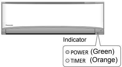
text_image
Power
Indicator
POWER (Green)
TIMER (Orange)
CS-TE/TZ20/25/35/42TKEW
CS-MTZ16TKE
text_image
INVERTER
AUTO
25.0°C
AUTO
12:00 AUTO
FAN
POWERSPLIT
QUIT
OFF/ON
○
FAN SPEED
MODE
TEMP
SLEEP
CS-TE50/60TKEW
CS-TZ50/60/71TKEW
text_image
INVERTER
AUTO
25.0
AUTO
AVR
AUTO
FAN
12:00 AUTO
FAN SPEED
POWER/QUET
OFF/ON
MODE
TEMP
SLEEP
ON
SET
TIMER
OFF
CANCEL
SET CHECK CLOCK AC RC
Panasonic
AIR CONDITIONER
Not used in normal operations.
Press to restore the remote control to default setting.
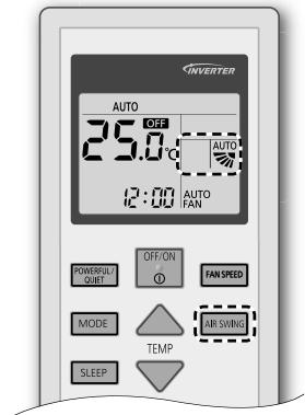
To adjust airflow direction
(CS-TE/TZ20/25/35/42TKEW, CS-MTZ16TKE)

flowchart
graph LR
    A["AIR SWING"] --> B["Upper direction"]
    B --> C["AUTO"]
    C --> D["→"]
    D --> E["→"]
    E --> F["→"]
    F --> G["→"]
- Do not adjust the flap by hand.
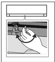
- For lateral direction, it is manually adjustable as shown.
natural_image
Illustration of a hand pressing a button on a surface, with no visible text or symbols
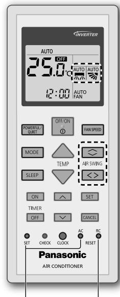
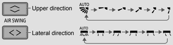
To adjust airflow direction
(CS-TE50/60TKEW, CS-TZ50/60/71TKEW)
flowchart
graph TD
    A["AIR SWING"] --> B["Upper direction"]
    C["Lateral direction"] --> D["Auto"]
    style A fill:#f9f,stroke:#333
    style C fill:#f9f,stroke:#333
    style B fill:#ccf,stroke:#333
    style D fill:#ccf,stroke:#333
- Do not adjust the flap by hand.
To adjust fan speed

flowchart
graph LR
    A["FAN SPEED"] --> B["AUTO FAN"]
    B --> C["1"]
    C --> D["2"]
    D --> E["3"]
    E --> F["4"]
    F --> G["5"]
    G --> H["6"]
    H --> I["7"]
    I --> J["8"]
    J --> K["9"]
    K --> L["10"]
- For AUTO, the indoor fan speed is automatically adjusted according to the operation mode.
- To have low noise priority operation, select the lowest fan speed (■).
To switch between powerful/quiet
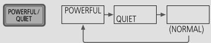
flowchart
graph TD
    A["POWERFUL / QUIET"] --> B["QUIET"]
    B --> C["(NORMAL)"]
    C --> A
POWERFUL:
To reach the preset temperature quickly
• This operation stops automatically after 20 minutes.
QUIET:
To enjoy quiet operation
- This operation reduces airflow noise.
To maximise comfort while sleeping
This operation provides you with a comfortable environment while sleeping. It will automatically adjust the sleep pattern temperature during the activation period. The indoor unit indicator will dim when this operation is activated. This is not applicable if the indicator brightness has been manually dimmed.

flowchart
graph TD
    A["SLEEP"] --> B["0.5h → 1.0h ... 9.0h → 0.0h"]
    B --> C["(Cancel)"]
This operation is incorporated with the activation timer (0.5, 1, 2, 3, 4, 5, 6, 7, 8 or 9 hours).
- This operation can be set together with timer. Sleep operation has the priority over OFF timer.
- This operation can be cancelled by pressing the respective button when the sleep timer reaches 0.0h.
To set the timer
2 sets of ON and OFF timers are available to turn ON or OFF the unit at different preset times.
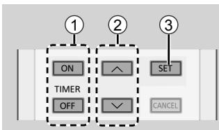
text_image
①
②
③
ON
SET
TIMER
OFF
✓
CANCEL
① Select ON or OFF timer
• Each time pressed:

② Set the time
③ Confirm
Example:
OFF at 22:00

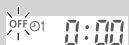

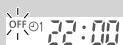

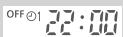
- To cancel ON or OFF timer, press ON or OFF to select respective ⊙1 or ⊙2 then press CANCEL.
- If timer is cancelled manually or due to power failure, you can restore the timer again by pressing ON or OFF to select respective ⏻1 or ⏻2 then press SET.
- The nearest timer setting will be displayed and will activate in sequence.
- Timer operation is based on the clock set in the remote control and repeats daily once set. For clock setting, please refer to Quick Guide.
Note
POWERFUL/QUIET
SLEEP
- Can be activated in all modes and can be cancelled by pressing the respective button again.
POWERFUL/QUIET
- Cannot be selected at the same time.
Operation mode
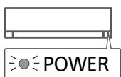
AUTO : During operation, the POWER indicator will blinks at initial.
Single
- Unit selects operation mode every 10 minutes according to the setting and room temperatures.
Multi
- Unit selects operation mode every 3 hours according to setting temperature, outdoor temperature and room temperature.
- It is possible to operate the indoor units individually or simultaneously. The priority of operation is placed on the first unit that turned on.
- During operation, HEAT and COOL modes cannot activate at the same time for different indoor units.
- The power indicator blinks to indicate the indoor unit is standing by for different operation mode.
HEAT : The POWER indicator blinks at the initial stage of this operation. Unit takes a while to warm up.
Multi
- For system which HEAT mode has been locked, if operation mode other than HEAT is selected, the indoor unit stops and the POWER indicator blinks.
COOL : Provides efficient comfort cooling to suit your needs.
DRY : Unit operates at low fan speed to give a gentle cooling operation.
Energy saving temperature setting
Operating the unit within the recommended temperature range may save energy.
HEAT : 20.0 °C \~ 24.0 °C / 68 °F \~ 75 °F.
COOL: 26.0 °C \~ 28.0 °C / 79 °F \~ 82 °F.
Air flow direction
In COOL/DRY mode:
(CS-TE/TZ20/25/35/42TKEW, CS-MTZ16TKE)
If AUTO is set, the flap swings up/down automatically.
(CS-TE50/60TKEW, CS-TZ50/60/71TKEW)
If AUTO is set, the flap swings left/right and up/down automatically.
In HEAT mode:
If AUTO is set, the horizontal flap is fixed at the predetermined position. The vertical flap swings left/right after the temperature rises.
Auto restart control
If power is resumed after a power failure, the operation will restart automatically after a period of time with previous operation mode and airflow direction.
- This control is not applicable when TIMER is set.
Operating conditions
Use this air conditioner in the temperature range indicated in the table.
| Temperature °C (°F) | Indoor | Single split outdoor unit *1 | Multi split outdoor unit *2 |
| DBT | WBT | DBT | WBT | DBT | WBT |
| COOL | Max. | 32 (89.6) | 23 (73.4) | 43 (109.4) | 26 (78.8) | 46 (114.8) | 26 (78.8) |
| Min. | 16 (60.8) | 11 (51.8) | -10 (14.0) | - | -10 (14.0) | - |
| HEAT | Max. | 30 (86.0) | - | 24 (75.2) | 18 (64.4) | 24 (75.2) | 18 (64.4) |
| Min. | 16 (60.8) | - | -15 (5.0) | -16 (3.2) | -15 (5.0) | -16 (3.2) |
| Temperature °C (°F) | Multi split outdoor unit *3 |
| DBT | WBT |
| COOL | Max. | 43 (109.4) | 26 (78.8) |
| Min. | 16 (60.8) | 11 (51.8) |
| HEAT | Max. | 24 (75.2) | 18 (64.4) |
| Min. | -10 (14.0) | -11 (12.2) |
DBT: Dry bulb temperature, WBT: Wet bulb temperature
*1 CU-TE20TKE, CU-TE25TKE, CU-TE35TKE, CU-TE42TKE, CU-TE50TKE, CU-TE60TKE, CU-TZ20TKE, CU-TZ25TKE, CU-TZ35TKE, CU-TZ42TKE, CU-TZ50TKE, CU-TZ60TKE, CU-TZ71TKE
*2 CU-3E18PBE, CU-4E23PBE, CU-4E27PBE, CU-5E34PBE, CU-2E12SBE, CU-2E15SBE, CU-2E18SBE, CU-3E23SBE, CU-2Z35TBE, CU-2Z41TBE, CU-2Z50TBE, CU-3Z52TBE, CU-3Z68TBE, CU-4Z68TBE, CU-4Z80TBE, CU-5Z90TBE
*3 CU-2RE15SBE, CU-2RE18SBE, CU-3RE18SBE, CU-2TZ41TBE, CU-2TZ50TBE, CU-3TZ52TBE
To ensure optimal performance of the unit, cleaning has to be carried out at regular intervals. Dirty unit may cause malfunction and you may see error code "H 99". Please consult authorised dealer.
- Switch off the power supply and unplug before cleaning.
- Do not touch the aluminium fin, sharp parts may cause injury.
- Do not use benzine, thinner or scouring powder.
- Use only soap (≈ pH 7) or neutral household detergent.
- Do not use water hotter than 40^ / 104^ .
Indoor unit
Wipe the unit gently with a soft, dry cloth.
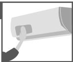
Outdoor unit
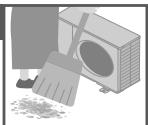
Make sure the air outlet of the outdoor unit is not blocked by fallen leaves or snow.
Clear any blockage from the drain pipe.
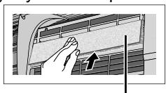
Air Purifying Filter
- Do not wash/rinse the filter with water.
- Replace the filter every 2 years or replace
any damaged filter.
Part no.: CZ-SA31P
natural_image
Illustration of a hand pressing down on a car air conditioner cover (no text or symbols visible)
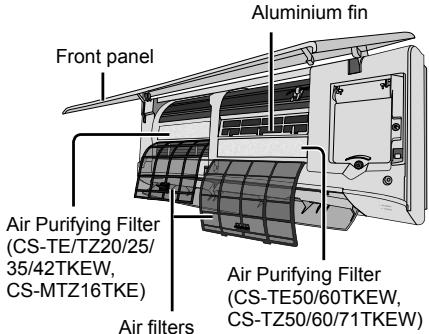
Air Purifying Filter
Indoor unit
text_image
Aluminium fin
Front panel
Air Purifying Filter
(CS-TE/TZ20/25/
35/42TKEW,
CS-MTZ16TKE)
Air purifying Filter
(CS-TE50/60TKEW,
CS-TZ50/60/71TKEW)
Air filters
Air filters
Once every 2 weeks
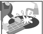
- Wash/rinse the filters gently with water to avoid damage to the filter surface.
- Replace any damaged filters.
- Dry the filters thoroughly under shade, away from fire or direct sunlight.
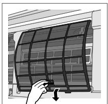
Remove air filter
natural_image
Illustration of a hand holding a curved panel next to a window, with no visible text or symbols.
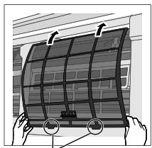
Attach air filter
natural_image
Illustration of a flexible solar panel being held, showing grid structure and mounting points (no text or symbols)
Insert into the unit
Front panel
Wash gently and dry.
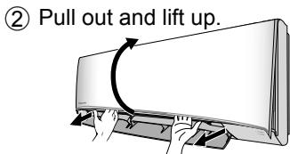
Remove the front panel
text_image
② Pull out and lift up.
① Release the hooks at both ends.
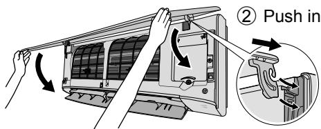
Close it securely
text_image
② Push in
① Insert at both sides.
③ Close down.
④ Press both ends and center of the front panel.
The following symptoms do not indicate malfunction.
| Symptom | Cause |
| Mist emerges from indoor unit. | Condensation effect due to cooling process. |
| Water flowing sound during operation. | Refrigerant flow inside the unit. |
| The room has a peculiar odour. | This may be due to damp smell emitted by the wall, carpet, furniture or clothing. |
| Indoor fan stops occasionally during automatic fan speed setting. | This helps to remove the surrounding odour. |
| Airflow continues even after operation has stopped. | Extraction of remaining heat from the indoor unit (maximum 30 seconds). |
| Operation is delayed a few minutes after restarting. | The delay is a protection to the unit's compressor. |
| Outdoor unit emits water/steam. | Condensation or evaporation occurs on pipes. |
| TIMER indicator is always on. | The timer setting repeats daily once set. |
| POWER indicator blinks during HEAT mode with no warm air supply (and flap is closed). | The unit is in defrost mode (and AIR SWING is set to AUTO). |
| Indoor fan stops occasionally during heating operation. | To avoid unintended cooling effect. |
| POWER indicator blinks before the unit is switched on. | This is a preliminary step in preparation for the operation when the ON timer has been set. When ON Timer is set, the unit may start earlier (up to 35 minutes) before the actual set time in order to achieve the desired temperature on time. |
| Cracking sound during operation. | Changes of temperature caused the expansion/contraction of the unit. |
| Dusts accumulated on the wall. | Due to air circulation or static electricity generated by the air conditioner. Some types of wall paper may collect dusts easily (recommended to clean the area around the air conditioner frequently). |
| During COOL/DRY mode, the indoor unit stops and POWER indicator blinks. | The system has locked to operate in HEAT model only. |
| Discoloration of some plastic parts. | Discoloration is subject to material types used in plastic parts, accelerated when exposed to heat, sun light, UV light or environmental factor. |
| Cooling/heating capacity reduced during the lowest fan speed setting. | The low fan speed is low noise priority operation, so cooling/heating capacity may be reduced (depending on the condition). Increase the Fan Speed to increase the capacity. |
Check the following before calling for servicing.
| Symptom | Check |
| Operation in HEAT/COOL mode is not working efficiently. | Set the temperature correctly.Close all doors and windows.Clean or replace the filters.Clear any obstruction at the air inlet and air outlet vents. |
| Noisy during operation. | Check if the unit has been installed at an incline.Close the front panel properly. |
| Remote control does not work. (Display is dim or transmission signal is weak.) | Insert the batteries correctly.Replace weak batteries. |
| The unit does not work. | Check if the circuit breaker is tripped.Check if timers have been set. |
| The unit does not receive the signal from the remote control. | Make sure the receiver is not obstructed.Certain fluorescent lights may interfere with signal transmitter. Please consult authorised dealer. |
When...
■The remote control is missing or a malfunction has occurred

text_image
AUTO
OFF/ON
- Raise the front panel.
- Press the button once to use in AUTO mode.
- Press and hold the button until you hear 1 beep, then release to use in forced COOL mode.
- Repeat step 3. Press and hold the button until you hear 2 beeps, then release to use in forced HEAT mode.
- Press the button again to turn off.
■The indicators are too bright
- To dim or restore the unit's indicator brightness, press and hold for 5 seconds.
■Conducting a seasonal inspection after extended non-use
- Check the remote control batteries.
- Check that there is no obstruction around the air inlet and outlet vents.
- Use Auto OFF/ON button to select COOL/HEAT operation. After 15 minutes of operation, it is normal to have the following temperature difference between the air inlet and outlet vents:
COOL: ≥ 8 °C / 14.4 °F
HEAT: ≥ 14 °C / 25.2 °F
■The units are not going to be used for a long period of time
- Activate HEAT mode for 2\~3 hours to remove moisture left in the internal parts thoroughly to prevent mould growth.
- Turn off the power supply and unplug.
- Remove the remote control batteries.
NON SERVICEABLE CRITERIAS
TURN OFF THE POWER SUPPLY AND UNPLUG then please consult an authorised dealer when in following conditions:
- Abnormal noise during operation.
• Water/foreign particles have entered the remote control.
• Water leaks from Indoor unit.
- Circuit breaker switches off frequently.
- Power cord becomes unnaturally warm.
- Switches or buttons are not functioning properly.
How to retrieve error codes
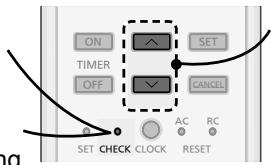
If the unit stops and the TIMER indicator blinks, use the remote control to retrieve the error code.
① Press for 5 seconds
③ Press for 5 seconds to quit checking
text_image
ON
TIMER
OFF
SET
SET CHECK CLOCK
AC
RC
RESET
CANCEL
②Press until you hear beep sound, then write down the error code
④ Turn the unit off and reveal the error code to authorised dealer
- For certain errors, you may restart the unit for limited operation if there are 4 beeps when operation starts.
| Diagnostic display | Abnormality/Protection control |
| H 00 | No memory of failure |
| H 11 | Indoor/outdoor abnormal communication |
| H 12 | Indoor unit capacity unmatched |
| H 14 | Indoor intake air temperature sensor abnormality |
| H 15 | Outdoor compressor temperature sensor abnormality |
| H 16 | Outdoor current transformer (CT) abnormality |
| H 19 | Indoor fan motor mechanism lock |
| H 21 | Indoor float switch operation abnormality |
| H 23 | Indoor heat exchanger temperature sensor 1 abnormality |
| H 24 | Indoor heat exchanger temperature sensor 2 abnormality |
| H 25 | Indoor ion device abnormality |
| H 27 | Outdoor air temperature sensor abnormality |
| H 28 | Outdoor heat exchanger temperature sensor abnormality |
| H 30 | Outdoor discharge pipe temperature sensor abnormality |
| H 32 | Outdoor heat exchanger temperature sensor 2 abnormality |
| H 33 | Indoor/outdoor misconnection abnormality |
| H 34 | Outdoor heat sink temperature sensor abnormality |
| H 35 | Indoor/outdoor water adverse current abnormality |
| H 36 | Outdoor gas pipe temperature sensor abnormality |
| Diagnostic display | Abnormality/Protection control |
| H 37 | Outdoor liquid pipe temperature sensor abnormality |
| H 38 | Indoor/outdoor mismatch (brand code) |
| H 39 | Abnormal indoor operating unit or standby units |
| H 41 | Abnormal wiring or piping connection |
| H 59 | Eco sensor abnormality |
| H 64 | Outdoor high pressure sensor abnormality |
| H 67 | nanoe abnormality |
| H 70 | Light sensor abnormality |
| H 97 | Outdoor fan motor mechanism lock |
| H 98 | Indoor high pressure protection |
| H 99 | Indoor operating unit freeze protection |
| F 11 | 4-way valve switching abnormality |
| F 17 | Indoor standby units freezing abnormality |
| F 90 | Power factor correction (PFC) circuit protection |
| F 91 | Refrigeration cycle abnormality |
| F 93 | Outdoor compressor abnormal revolution |
| F 94 | Compressor discharge pressure overshoot protection |
| F 95 | Outdoor cooling high pressure protection |
| F 96 | Power transistor module overheating protection |
| F 97 | Compressor overheating protection |
| F 98 | Total running current protection |
| F 99 | Outdoor direct current (DC) peak detection |
natural_image
Architectural line drawing of a modern living room interior with furniture and furniture (no text or symbols)
Guide Rapide
Insertion des piles
text_image
Diagram showing three labeled components of a battery pack assembly with arrows indicating direction
natural_image
Interior architectural rendering of a modern room with staircase, staircase, and ceiling air conditioner (no text or symbols)
CS-TE50/60TKEW
CS-TZ50/60/71TKEW
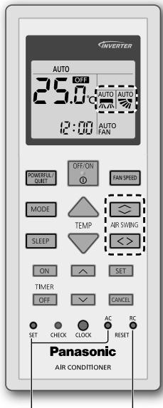
text_image
INVERTER
AUTO
25.0 °C AUTO AUTO
12:00 AUTO FAN
POWERFULL OUIF OFF/ON FAN SPEED
MODE TEMP ARP SWING
SLEEP < >
ON SET
TIMER
OFF CANCEL
SET CHECK CLOCK AC RC
SET RESET
Panasonic
AIR CONDITIONER
natural_image
Illustration of a hand holding a tool with an arrow indicating rotation (no text or symbols)
(CS-TE50/60TKEW, CS-TZ50/60/71TKEW)
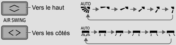
flowchart
graph TD
    A["AIR SWING"] --> B["Vers le haut"]
    C["<<"] --> D["Vers les côtés"]
    E["AUTO"] --> F["→"]
    G["AUTO"] --> H["→"]
    I["→"] --> J["→"]
    K["→"] --> L["→"]
flowchart
graph TD
    A["POWERFUL/QUIET"] --> B["QUIET"]
    B --> C["(NORMAL)"]
    C --> A
PUISSANT :
flowchart
graph TD
    A["SLEEP"] --> B["SLEEP 0.5h → 1.0h ... 9.0h → 0.0h"]
    B --> C["(Cancel)"]
(CS-TE50/60TKEW, CS-TZ50/60/71TKEW)
*1 CU-TE20TKE, CU-TE25TKE, CU-TE35TKE, CU-TE42TKE, CU-TE50TKE, CU-TE60TKE, CU-TZ20TKE, CU-TZ25TKE, CU-TZ35TKE, CU-TZ42TKE, CU-TZ50TKE, CU-TZ60TKE, CU-TZ71TKE
*2 CU-3E18PBE, CU-4E23PBE, CU-4E27PBE, CU-5E34PBE, CU-2E12SBE, CU-2E15SBE, CU-2E18SBE, CU-3E23SBE, CU-2Z35TBE, CU-2Z41TBE, CU-2Z50TBE, CU-3Z52TBE, CU-3Z68TBE, CU-4Z68TBE, CU-4Z80TBE, CU-5Z90TBE
*3 CU-2RE15SBE, CU-2RE18SBE, CU-3RE18SBE, CU-2TZ41TBE, CU-2TZ50TBE, CU-3TZ52TBE
natural_image
Hand inserting a component into an air conditioner panel (no text or symbols visible)
natural_image
Illustration of a hand holding a small object next to a curved panel array (no text or symbols visible)
natural_image
Illustration of hands installing a curved panel on a building facade (no text or symbols visible)
natural_image
Architectural line drawing of a modern living room interior with furniture and furniture (no text or symbols)
Guía Rápida
text_image
Diagram showing three labeled components of a battery pack assembly with arrows indicating direction
natural_image
Interior architectural rendering of a modern room with staircase, staircase, and ceiling air conditioner (no text or symbols)
CS-TE50/60TKEW
CS-TZ50/60/71TKEW
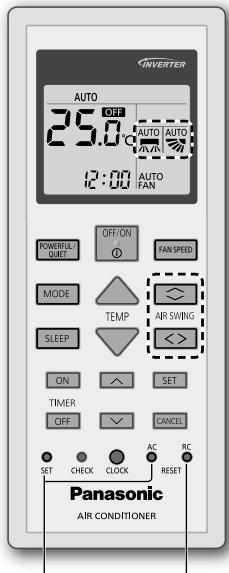
text_image
INVERTER
AUTO
25.0 °C AUTO AUTO
12:00 AUTO FAN
POWERFULL OUIF OFF/ON FAN SPEED
MODE TEMP ARP SWING
SLEEP < >
ON SET
TIMER
OFF CANCEL
SET CHECK CLOCK AC RC
SET RESET
Panasonic
AIR CONDITIONER
natural_image
Illustration of a hand holding a circular object with an arrow, next to a mechanical component (no text or symbols)
(CS-TE50/60TKEW, CS-TZ50/60/71TKEW)
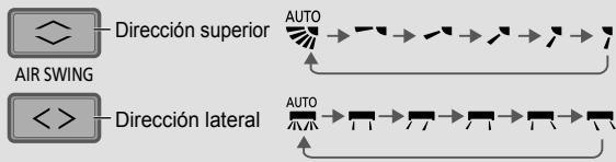
flowchart
graph LR
    A["AIR SWING"] --> B["Dirección superior"]
    C["DIRECCIÓN lateral"] --> D["AUTO"]
    B --> E["→"]
    D --> F["→"]
    E --> G["→"]
    F --> H["→"]
flowchart
graph TD
    A["SLEEP"] --> B["0.5h → 1.0h ... 9.0h → 0.0h"]
    B --> C["(Cancel)"]
(CS-TE50/60TKEW, CS-TZ50/60/71TKEW)
*1 CU-TE20TKE, CU-TE25TKE, CU-TE35TKE, CU-TE42TKE, CU-TE50TKE, CU-TE60TKE, CU-TZ20TKE, CU-TZ25TKE, CU-TZ35TKE, CU-TZ42TKE, CU-TZ50TKE, CU-TZ60TKE, CU-TZ71TKE
*2 CU-3E18PBE, CU-4E23PBE, CU-4E27PBE, CU-5E34PBE, CU-2E12SBE, CU-2E15SBE, CU-2E18SBE, CU-3E23SBE, CU-2Z35TBE, CU-2Z41TBE, CU-2Z50TBE, CU-3Z52TBE, CU-3Z68TBE, CU-4Z68TBE, CU-4Z80TBE, CU-5Z90TBE
*3 CU-2RE15SBE, CU-2RE18SBE, CU-3RE18SBE, CU-2TZ41TBE, CU-2TZ50TBE, CU-3TZ52TBE
natural_image
Illustration of a hand reaching toward a car air conditioner cover with an arrow indicating airflow direction (no text or symbols)
natural_image
Illustration of a hand holding a flexible solar panel next to a curved panel, with no visible text or symbols.
natural_image
Illustration of a curved solar panel mounted on a base, with hands adjusting its components (no text or symbols visible)
natural_image
Architectural line drawing of a modern living room interior with furniture and furniture (no text or symbols)
Kurzanleitung
text_image
Diagram showing three labeled components of a battery or motor assembly, with arrows indicating direction and polarity.
natural_image
Interior architectural rendering of a modern room with staircase, staircase, and ceiling air conditioner (no text or symbols)
CS-TE50/60TKEW
CS-TZ50/60/71TKEW
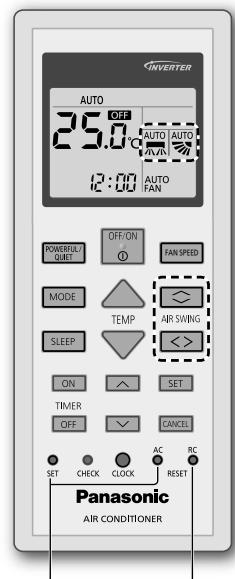
text_image
INVERTER
AUTO
25.0
AUTO
AVR
AUTO
FAN
12:00 AUTO
FAN SPEED
POWER/QUET
OFF/ON
MODE
TEMP
SLEEP
ON
SET
TIMER
OFF
CANCEL
SET CHECK CLOCK AC RC
AC RESET
Panasonic
AIR CONDITIONER
natural_image
Illustration of a hand pressing a button on a surface, with no visible text or symbols
(CS-TE50/60TKEW, CS-TZ50/60/71TKEW)
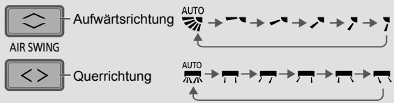
flowchart
graph TD
    A["AIR SWING"] --> B["Aufwärtsrichtung"]
    C["<<"] --> D["Querrichtung"]
    B --> E["AUTO"]
    D --> F["AUTO"]
    E --> G["→"]
    F --> H["→"]
    G --> I["→"]
    H --> J["→"]
    I --> K["→"]
    J --> L["→"]
text_image
SLEEP
SLEEP 0.5h → 1.0h ... 9.0h → 0.0h
(Cancel)
(CS-TE50/60TKEW, CS-TZ50/60/71TKEW)
*1 CU-TE20TKE, CU-TE25TKE, CU-TE35TKE, CU-TE42TKE, CU-TE50TKE, CU-TE60TKE, CU-TZ20TKE, CU-TZ25TKE, CU-TZ35TKE, CU-TZ42TKE, CU-TZ50TKE, CU-TZ60TKE, CU-TZ71TKE
*2 CU-3E18PBE, CU-4E23PBE, CU-4E27PBE, CU-5E34PBE, CU-2E12SBE, CU-2E15SBE, CU-2E18SBE, CU-3E23SBE, CU-2Z35TBE, CU-2Z41TBE, CU-2Z50TBE, CU-3Z52TBE, CU-3Z68TBE, CU-4Z68TBE, CU-4Z80TBE, CU-5Z90TBE
*3 CU-2RE15SBE, CU-2RE18SBE, CU-3RE18SBE, CU-2TZ41TBE, CU-2TZ50TBE, CU-3TZ52TBE
natural_image
Hand pressing down on a car air conditioner cover with a directional arrow (no text or symbols visible)
natural_image
Illustration of a hand holding a solar panel next to a curved panel, with no visible text or symbols.
natural_image
Illustration of a curved solar panel mounted on a wall, with hands adjusting its base (no text or symbols visible)
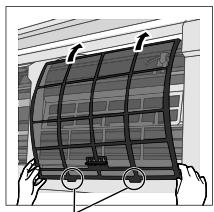
Im Gerät einhaken
Frontverkleidung
natural_image
Architectural line drawing of a modern living room with furniture and furniture (no text or symbols)
Guida Rapida
text_image
Diagram showing three labeled components of a battery or motor assembly, with arrows indicating direction and polarity.
natural_image
Interior architectural rendering of a modern room with staircase, staircase, and ceiling air conditioner (no text or symbols)
CS-TE50/60TKEW
CS-TZ50/60/71TKEW
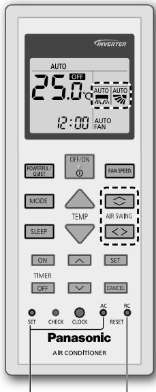
text_image
INVERTER
AUTO
25.0 °C AUTO AUTO
12:00 AUTO FAN
POWERFULL OUIF OFF/ON FAN SPEED
MODE TEMP ARP SWING
SLEEP < >
ON SET
TIMER
OFF CANCEL
SET CHECK CLOCK AC RC
SET RESET
Panasonic
AIR CONDITIONER
natural_image
Illustration of a hand holding a circular object with an arrow, next to a mechanical component (no text or symbols)
(CS-TE50/60TKEW, CS-TZ50/60/71TKEW)
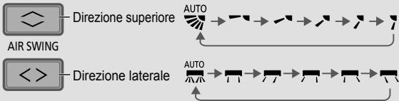
flowchart
graph LR
    A["AIR SWING"] --> B["Direzione superiore"]
    B --> C["AUTO"]
    C --> D["→"]
    D --> E["→"]
    E --> F["→"]
    F --> G["→"]
    G --> H["→"]
    H --> I["→"]
    I --> J["→"]
    J --> K["AUTO"]
    K --> L["→"]
    L --> M["→"]
    M --> N["→"]
    N --> O["→"]
    O --> P["→"]
    P --> Q["→"]
    Q --> R["AUTO"]
    R --> S["→"]
    S --> T["→"]
    T --> U["→"]
    U --> V["→"]
    V --> W["→"]
    W --> X["→"]
    X --> Y["→"]
    Y --> Z["AUTO"]
    Z --> AA["→"]
    AA --> AB["→"]
    AB --> AC["→"]
    AC --> AD["→"]
    AD --> AE["→"]
    AE --> AF["→"]
    AF --> AG["AUTO"]
flowchart
graph TD
    A["POWERFUL/QUIET"] --> B["QUIET"]
    B --> C["(NORMAL)"]
    C --> A
POTENTE:
text_image
SLEEP
SLEEP 0.5h → 1.0h ... 9.0h → 0.0h
(Cancel)
(CS-TE50/60TKEW, CS-TZ50/60/71TKEW)
*1 CU-TE20TKE, CU-TE25TKE, CU-TE35TKE, CU-TE42TKE, CU-TE50TKE, CU-TE60TKE, CU-TZ20TKE, CU-TZ25TKE, CU-TZ35TKE, CU-TZ42TKE, CU-TZ50TKE, CU-TZ60TKE, CU-TZ71TKE
*2 CU-3E18PBE, CU-4E23PBE, CU-4E27PBE, CU-5E34PBE, CU-2E12SBE, CU-2E15SBE, CU-2E18SBE, CU-3E23SBE, CU-2Z35TBE, CU-2Z41TBE, CU-2Z50TBE, CU-3Z52TBE, CU-3Z68TBE, CU-4Z68TBE, CU-4Z80TBE, CU-5Z90TBE
*3 CU-2RE15SBE, CU-2RE18SBE, CU-3RE18SBE, CU-2TZ41TBE, CU-2TZ50TBE, CU-3TZ52TBE
natural_image
Hand pressing down on a car air conditioner cover with a directional arrow (no text or symbols visible)
natural_image
Illustration of a hand holding a flexible solar panel next to a curved panel, with no visible text or symbols.
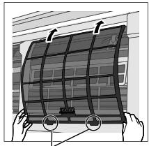
natural_image
Illustration of a curved solar panel mounted on a wall, with hands adjusting its base (no text or symbols visible)
Inserire nell'unità
Pannello anteriore
Wash gently and dry.
text_image
② Spingere.
natural_image
Architectural line drawing of a modern living room with furniture and furniture (no text or symbols)
Snelle Gids
text_image
Diagram illustrating battery charging process with labeled components and directional arrows
natural_image
Interior architectural rendering of a modern room with staircase, staircase, and ceiling air conditioner (no text or symbols)
These symbols denote actions COMPULSORY.
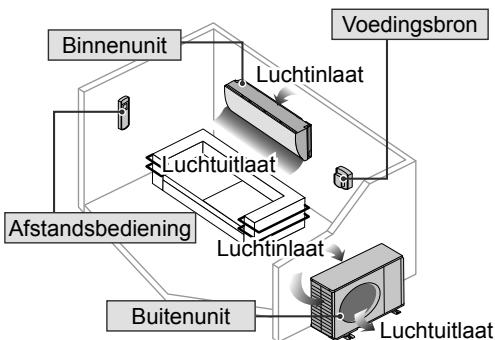
flowchart
graph TD
    A["Binnenunit"] --> B["Luchtinlaat"]
    C["Voedingsbron"] --> D["Luchtinlaat"]
    E["Afstandsbediening"] --> F["Luchtuitlaat"]
    G["Buitenunit"] --> H["Luchtuitlaat"]
    I["Binnenunit"] --> J["Luchtinlaat"]
    K["Voedingsbron"] --> L["Luchtuitlaat"]

WAARSCHUWING
CS-TE50/60TKEW
CS-TZ50/60/71TKEW
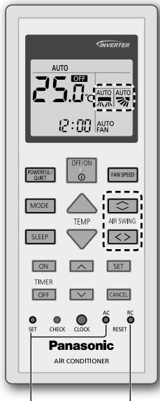
text_image
INVERTER
AUTO
25.0 °C AUTO AUTO
12:00 AUTO FAN
POWERFULL OUIF OFF/ON FAN SPEED
MODE TEMP ARP SWING
SLEEP < >
ON SET
TIMER
OFF CANCEL
SET CHECK CLOCK AC RC
SET RESET
Panasonic
AIR CONDITIONER
natural_image
Illustration of a hand holding a tool with an arrow, next to a screen (no text or symbols)
(CS-TE50/60TKEW, CS-TZ50/60/71TKEW)
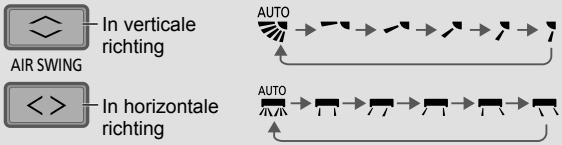
flowchart
graph TD
    A["In verticale richting"] --> B["AUTO"]
    C["In horizontale richting"] --> D["AUTO"]
    style A fill:#f9f,stroke:#333
    style C fill:#f9f,stroke:#333
    style B fill:#ccf,stroke:#333
    style D fill:#ccf,stroke:#333
flowchart
graph TD
    A["POWERFUL/QUIET"] --> B["QUIET"]
    B --> C["(NORMAL)"]
    C --> A
MET KRACHT:
flowchart
graph TD
    A["SLEEP"] --> B["SLEEP 0.5h → 1.0h ... 9.0h → 0.0h"]
    B --> C["(Cancel)"]
(CS-TE50/60TKEW, CS-TZ50/60/71TKEW)
*1 CU-TE20TKE, CU-TE25TKE, CU-TE35TKE, CU-TE42TKE, CU-TE50TKE, CU-TE60TKE, CU-TZ20TKE, CU-TZ25TKE, CU-TZ35TKE, CU-TZ42TKE, CU-TZ50TKE, CU-TZ60TKE, CU-TZ71TKE
*2 CU-3E18PBE, CU-4E23PBE, CU-4E27PBE, CU-5E34PBE, CU-2E12SBE, CU-2E15SBE, CU-2E18SBE, CU-3E23SBE, CU-2Z35TBE, CU-2Z41TBE, CU-2Z50TBE, CU-3Z52TBE, CU-3Z68TBE, CU-4Z68TBE, CU-4Z80TBE, CU-5Z90TBE
*3 CU-2RE15SBE, CU-2RE18SBE, CU-3RE18SBE, CU-2TZ41TBE, CU-2TZ50TBE, CU-3TZ52TBE
natural_image
Hand holding a car air conditioner cover with a vertical arrow pointing to the cover (no text or symbols visible)
natural_image
Illustration of a hand holding a solar panel next to a curved panel, with no visible text or symbols.
Luchtfilter bevestigen
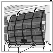
natural_image
Illustration of a curved solar panel being mounted on a wall, with hands adjusting its components (no text or symbols visible)
text_image
ON
TIMER
OFF
SET
SET
CANCEL
SET CHECK CLOCK AC RC
RESET

These symbols on the products, packaging, and/or accompanying documents mean that used electrical and electronic products and batteries should not be mixed with general household waste.
For proper treatment, recovery and recycling of old products and used batteries, please take them to applicable collection points, in accordance with your national legislation.
By disposing of these products and batteries correctly, you will help to save valuable resources and prevent any potential negative effects on human health and the environment which could otherwise arise from inappropriate waste handling.
For more information about collection and recycling of old products and batteries, please contact your local municipality, your waste disposal service or the point of sale where you purchased the items.
Penalties may be applicable for incorrect disposal of this waste, in accordance with national legislation.

For business users in the European Union
If you wish to discard electrical and electronic equipment, please contact your dealer or supplier for further information.
These symbols are only valid in the European Union. If you wish to discard these items, please contact your local authorities or dealer and ask for the correct method of disposal.
Note for the battery symbol (bottom two symbol examples):
This symbol might be used in combination with a chemical symbol. In this case it complies with the requirement set by the Directive for the chemical involved.
Français
1006 Kadoma, Kadoma City,
Osaka, Japan
Website: http://www.panasonic.com
© Panasonic Corporation 2016
Printed in Malaysia
Authorised representative in EU
Panasonic Testing Centre
Panasonic Marketing Europe GmbH
Winsbergring 15, 22525 Hamburg, Germany