
KHB90FBC1 - Range hood PANASONIC - Free user manual and instructions
Find the device manual for free KHB90FBC1 PANASONIC in PDF.
| Brand | Panasonic |
| Model | KHB90FBC1 |
| Product type | Range hood |
| Installation | Wall-mounted or island |
| Exhaust version | External extraction (exhaust) or internal recirculation (filtration) |
| Number of speeds | 4 speeds + recirculation function |
| Lighting | High-efficiency LED spotlights |
| Grease filters | Dishwasher-safe metal filters, clean monthly |
| Charcoal filters | Not washable, replace every 3-4 months |
| Filter alarm | Alarm for grease filter after 30 hours of operation |
| Timer | Programmable automatic shut-off (15 minutes) |
| Minimum distance to cooking surface | 65 cm (may vary according to cooktop instructions) |
| Exhaust duct diameter | 150 mm (150-120 mm reducer included) |
| Power supply | Single-phase 220-240 V ~ 50/60 Hz (check rating plate) |
| Maximum power | Not specified in the manual (refer to rating plate) |
| Weight | Not specified in the manual |
| Dimensions (W x D x H) | Not specified in the manual (refer to mounting template) |
| Noise level | Not specified in the manual |
| Energy class | Not specified in the manual |
| Exterior maintenance | Damp cloth, neutral detergent or denatured alcohol |
| Warranty | Refer to the provided warranty certificate |
Frequently Asked Questions - KHB90FBC1 PANASONIC
User questions about KHB90FBC1 PANASONIC
0 question about this device. Answer the ones you know or ask your own.
Ask a new question about this device
Download the instructions for your Range hood in PDF format for free! Find your manual KHB90FBC1 - PANASONIC and take your electronic device back in hand. On this page are published all the documents necessary for the use of your device. KHB90FBC1 by PANASONIC.
USER MANUAL KHB90FBC1 PANASONIC
natural_image
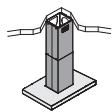
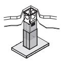
Isometric line drawing of a tall cylindrical structure mounted on a base (no text or symbols)KH-B90FBW1
Cooker Hood
Dunstabzugshaube
Hotte
Dampkap
Cappa da cucina
Campana Extractora
Emhætte
Spiskåpa
Kjøkkenventilator
Model No.
KH-B90FBC1
KH-B90FBW1
OPERATING INSTRUCTIONS
BEDIENUNGSANLEITUNG
MODE D'EMPLOI
BEDIENINGSINSTRUCTIES
ISTRUZIONI D'USO
INSTRUCCIONES DE USO
BRUGSVEJLEDNING
ANVÄNDARINSTRUKTIONER
BRUKSANVISNING
ZY02-C68
Fa1212K0
Thank you for purchasing this Panasonic appliance. Please read this instructions carefully before using the appliance. Keep Operating Instructions and Guarantee Certificate for future use. This appliance is intended for domestic use.
* Installation Instructions is included.
A1
B1
C1
D1

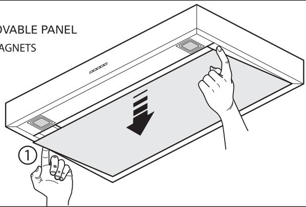
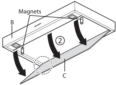
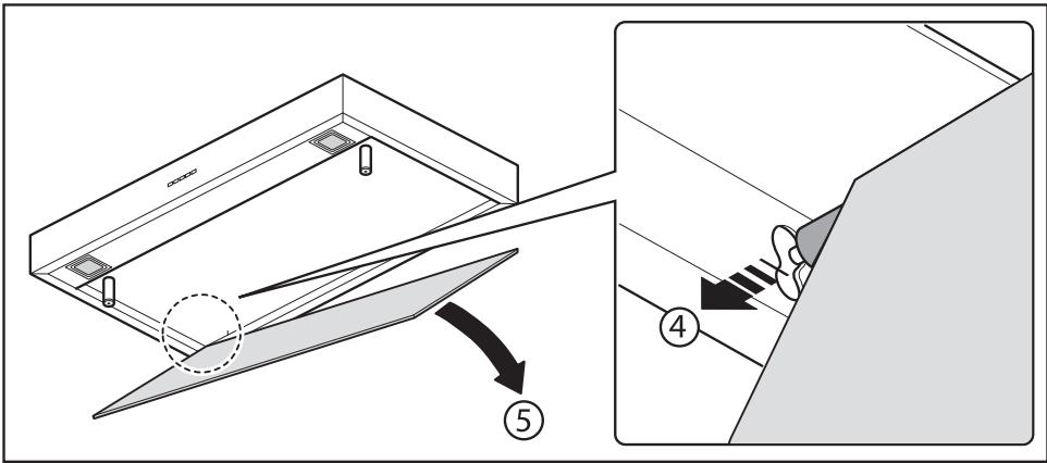
INSTRUCTION FOR REMOVABLE PANEL NEW FIXING SYSTEM WITH MAGNETS
Contents
A: WARNINGS 12
B: TECHNICAL SPECIFICATIONS 13
C: INSTALLATION 13
D: ELECTRICAL CONNECTIONS 14
E: HOOD VERSION WITH EXTERNAL EXHAUST 14
F: HOOD VERSION WITH INTERNAL RECIRCULATION (filtering) 15
G: ELECTRONIC PUSH BUTTON CONTROL PANEL FUNCTIONING 15
H: FILTERS removing and replacing's instructions 16
I: LED SPOTLIGHT ILLUMINATION 17
J: MAINTENANCE AND CLEANING 17
K: MOUNTING HOOD INSTRUCTIONS 17
Inhalt
E: KJ∅KKENVENTILATOR I VERSJON UTLUFTING 83
F: KJ∅KKENVENTILATOR I VERSJON OMLUFT (filtrering) 83
G: SLIK VIRKER DET ELEKTRONISKE TRYKKNAPPANELET 84
This instruction booklet must be kept together with the appliance for future reference. If the appliance is sold or consigned to other parties, check that the booklet is supplied with it, to ensure that the new user has the correct information on the operation of the cooker hood and is aware of the warnings. These warnings have been provided for the your safety and the safety of others. As a result, please read them carefully before installing and operating the appliance.
This appliance is not intended for use by young children or infirm persons unless they have been adequately supervised by a responsible person to ensure that they can use the appliance safely. Young children should be supervised to ensure they do not play with the appliance.
The appliance must be installed by qualified personnel, in accordance with the standards in force. In case of malfunction or breakdown, immediately stop using the appliance. Turn off the circuit breaker, and then contact the service centre. Failure to do this may cause smoke, burns, and electric shock.
Breakdown examples:
- Burning smell comes from the appliance.
- Can feel electricity when touching the appliance.
If the supply cord is damaged, it must be re-placed by the manufacturer, its service agent or similarly qualified persons in order to avoid a hazard. Any modifications that may be required to the electrical system for the installation of the cooker hood must only be made by qualified electricians.
It is dangerous to modify or attempt to modify the characteristics of this system. In the event of malfunctions or if repairs are required to the appliance, do not attempt to solve the problems directly.
Repairs performed by unqualified persons may cause damage. For all repair and other work on the appliance, contact the service centre.
Always check that all the electrical parts (lights, exhaust device), are off when the appliance is not being used. Turn off the circuit breaker when the appliance will not be used for a long period of time. Read the entire instruction booklet before performing any operations on the cooker hood.
The cooker hood must only be used for the exhaust of cooking fumes in home kitchens. The manufacturer disclaims all liability for any other use of the appliance.
The maximum weight of any object placed above the hood, or hung to it (if possible) must not exceed 1.5 kilos. After installing the stainless steel hood, clean it in order to remove any residue of the protective glue, and stains of grease or oil. The manufacturer recommends its cleaning cloth available for purchase. The manufacturer accepts no liability in case of damage caused by the use of different detergent types.
SAFETY WARNINGS
CE

The electrical system features an earth connection in compliance with international safety standards; furthermore, it is compliant with the European standard for electromagnetic compatibility. This appliance must be properly earthed following the electric laws. Earth line must not be connected to gas pipe, water pipe, earth of lightning rod and telephone. Install dedicated single-phase circuit with the adequate rated circuit breaker for the power supply.
Do not connect the appliance to flues (from boilers, fireplaces, etc.). Make sure the mains volt-
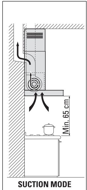
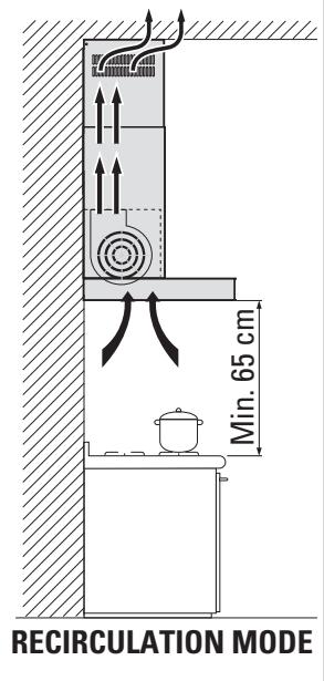
age corresponds to the values on the rating plate located inside the cooker hood. The minimum safety distance between the cooktop and the cooker hood must be at least 65 cm.
Never cook on "open" flames under the cooker hood.
Check deep-fryers during use: superheated oil may be flammable.
- Ensure there is adequate ventilation of the room when the cooker hood is used at the same time as appliances burning gas or other fuels.
- Do not flambe under the cooker hood.
- The exhaust air must not be discharged into a flue which is used for exhausting fumes from appliances burning gas or other fuels.
- Ensure that all regulations concerning the discharge of exhaust air have been fulfilled before you use the appliance.
Accessible parts may become hot when used with cooking appliance. Wear work gloves for all installation and maintenance operations. Before performing any cleaning or maintenance operations, disconnect the appliance by unplugging it or using the main switch. The manufacturer disclaims all liability for any damage that may be directly or indirectly caused to people, things and animals due to the failure to follow all the instructions provided in this booklet and above all the warnings relating to the installation, operation and maintenance of the appliance.
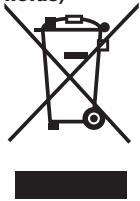
DISPOSAL OF WASTE PRODUCTS
Information on disposal for users of waste electrical & electronic equipment (private households)
natural_image
Symbol of a trash bin crossed out by two crossed lines, with no text or labels present.This symbol on the products and/or accompanying documents means that used electrical and electronic products should not be mixed with general household waste.
For proper treatment, recovery and recycling, please take these products to designated collection points, where they will be accepted on a free of charge basis. Alternatively, in some countries you may be able to return your products to your local retailer upon the purchase of an equivalent new product.
Disposing of this product correctly will help to save valuable resources and prevent any potential negative effects on human health and the environment which could otherwise arise from inappropriate waste handling. Please contact your local authority for further details of your nearest designated disposable point.
Penalties may be applicable for incorrect disposal of this waste, in accordance with national legislation.
Information on disposal in other countries outside the European Union
This symbol is only valid in the European Union.
If you wish to discard this product, please contact your local authorities or dealer and ask for the correct method of disposal.

TECHNICAL SPECIFICATIONS
The technical specifications of the appliance are shown on the rating plates located inside the cooker hood.

INSTALLATION
(Section reserved for qualified installers of the cooker hood)
The distance between the hob and the lowest part of the kitchen cooker hood cannot be smaller than X=65 cm. Should the instructions of the gas hob specify a greater distance, take this
into consideration.
In the outside suction version, the diameter of the fume discharge duct must be no smaller than the cooker hood connection. We recommend using pipes with 150 mm diameter.
If using pipes with 120 mm diameter, install attached "reducer (150-120 mm)" to the discharge hole of the cooker hood.
When screwing or installing the metallic duct to the wall which metal lath, wire lath or metal plate is lined, do not let them come in contact with metal part. Otherwise, it may cause electric leakages or fires.
In the horizontal sections, the duct must slope slightly (around 10%) upwards, so at to better convey the air outside of the room. The duct must be installed not to bend it in the immediate vicinity of the discharge hole. Otherwise, the return valve will get stuck with the duct, and will not work for the exhaust properly. Reduce curves to the bare minimum, and check that the length of the ducts is also the bare minimum.
Comply with the current regulations on air discharge into the atmosphere.
If other appliances that use gas or other fuels are being used at the same time (boiler, stove, fireplaces, etc.), make sure the room where the fumes are extracted is well ventilated, in compliance with the current regulations.
Assembly instructions: see section "K" of the booklet.

ELECTRICAL CONNECTIONS
(Section reserved for qualified installers)
WARNING!
Before doing any work inside the cooker hood, disconnect the appliance from the mains power supply.
Check that the wires inside the cooker hood are not disconnected or cut; if this is the case, contact your nearest service centre. The electrical connections must be performed by qualified personnel.
The connections must be performed in compliance with the legal standards in force. Check that the relief valve and the electrical system are able to support the load of the appliance (see the technical specifications in point B).
This appliance is supplied with a cable without plug. Standardized plugs must be used, keeping in mind that:
- the yellow-green wire must be used for the earth,
- the blue wire must be used for the neutral,
- the brown wire must be used for the phase; the cable must not come into contact with hot parts (over 70°C).
- fit a plug that is suitable for the load to the power cable, and connect it to a suitable power outlet.
Please refer to a qualified person. (See technical specifications in point B).
WARNING!
The supply cord must be set properly not to be damaged. The manufacturer declines all liability if the safety standards are not observed.

HOOD VERSION WITH EXTERNAL EXHAUST
In this version the kitchen fumes and vapours are conveyed outside through an exhaust pipe. The exhaust conveyor that protrudes from the upper part of the hood must be connected with the pipe that conducts the fumes and vapours in an external output.
In this version, charcoal filters supplied on the hoods must not be used.
When the kitchen hood is used simultaneously with other appliances that use gas or other fuels, the room must have sufficient ventilation according to the standards in force.
Deviation for Germany:
When the cooker hood and appliances supplied with energy other than electricity are simultaneously in operation, the negative pressure in the room must not exceed 4 Pa (4x10 E-5 bar).

HOOD VERSION WITH INTERNAL RECIRCULATION (filtering)
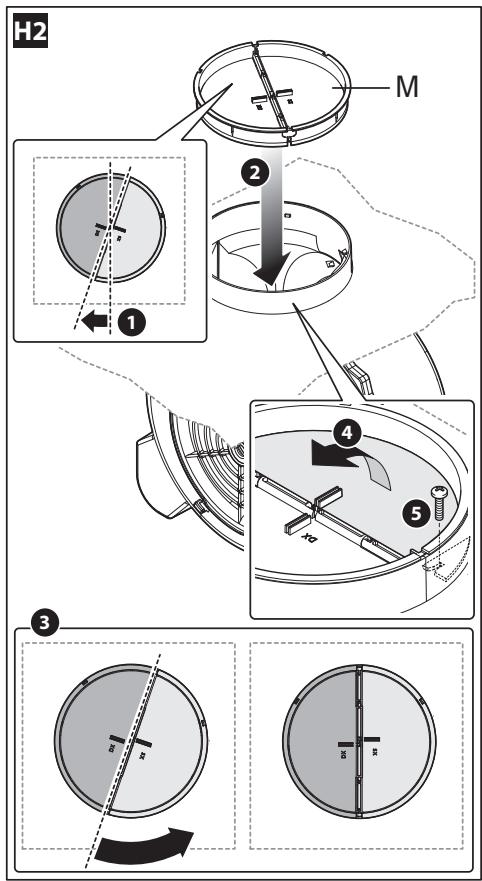
In this model, the area passes through the charcoal filters to be purified and is then introduced into the kitchen environment. To mount the filters, refer to section H2.
For maximum efficiency, the third speed should be used when there are strong odours or a lot of steam, the second speed in normal conditions, and the first speed for keeping the air clean with minimum energy consumption. The cooker hood should be switched on when starting to cook, and left on until the odours disappear.

ELECTRONIC PUSH BUTTON CONTROL PANEL FUNCTIONING
1
2

3

4

5
6
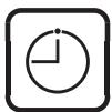
Key 1: Timer/Filter alarm
The BLUE fix light indicates that the grease filter alarm is active (after 30 hours); to deactivate this alarm and reset the hour meter, press the button for 3 seconds.
BLUE flashing light indicates that the timer function is active. This function can be activated only if the motor is already active with any speed when the key is pressed (prolonged pressure or not). This function activates the auto power off function of the cooker hood after 15 minutes with the active Timer function, the cooker hood can be turned off by the user and the function will be disabled. The Timer function remains associated to a speed. The speed change with the active timer function determines its deactivation.
Key 2: 1st Speed +On/Off motor
A slight pressure of the key activates the hood at the first speed and the relative LED.
When the LED is on and the key is pressed, both the LED and MOTOR will turn off.
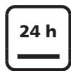
When the LED is off, if the key is pressed for at least 3sec, the recirculation function activates. During the recirculation function (which lasts 24 hours), the LED flashes.
From the activation of this function, the cooker hood will remain active for 1 hour at 1st speed, then it will stop for 3 hours and reactivate for another hour. These cycles are repeated until timeout. With activation of this function, other speeds may not be selected. To deactivate this function, keep key 2 pressed for at least 3 seconds.
Key 3: 2nd Speed
If the LED is off and another speed is active, press the key (slightly or prolonged) to select the 2nd speed, turn the relative LED on and turn the LED associated to the previously selected speed off.
If the LED is off and no speed is active, the key is disabled.
When the LED is on, key 3 is disabled.
To turn off the cooker hood, select the first speed and press that key again.
Key 4: 3rd Speed
If the LED is off and another speed is active, press the key (slightly or prolonged) to select the 3rd speed, turn the relative LED on and turn the LED associated to the previously selected speed off.
If the LED is off and no speed is active, the key is disabled.
When the LED is on, key 4 is disabled.
To turn off the cooker hood, select the first speed and press that key again.
Key 5: 4th Speed
If the LED is off and another speed is active, press the key (slightly or prolonged) to select the 4th speed, turn the relative LED on and turn the LED associated to the previously selected speed off.
If the LED is off and no speed is active, the key is disabled.
When the LED is on, key 5 is disabled.
The fourth speed lasts 14 minutes, then the cooker hood returns to the third speed.
To turn off the cooker hood, select the first speed and press that key again.
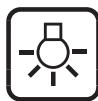
Key 6: Light
Light: Briefly pressing key T6 will turn the light on and off. The T6 key lights on if the light is on.
Key pressure management
Prolonged pressure = finger pressed on key for at least 3 seconds, the function activates during pressure.
Non-prolonged pressure = finger pressed on key for less than 3 seconds, the function activates upon its release.

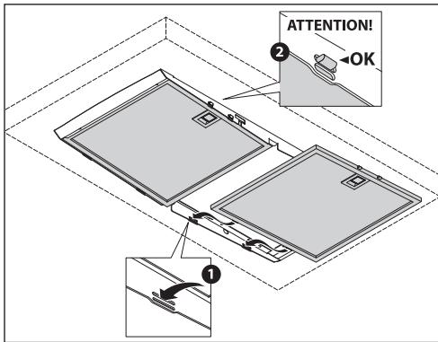
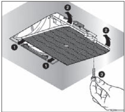
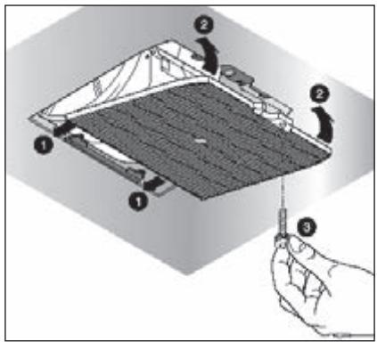
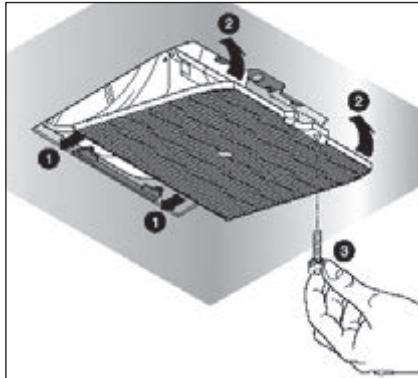
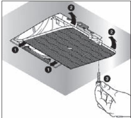
FILTERS REMOVING AND REPLACING'S INSTRUCTIONS
1. METAL FILTERS
Open the panel (see fig. H1). To remove the grease-trapping metallic filters pull on the handles. To place the grease-trapping metallic filters, insert the tabs into the holes as illustrated in the lower left figure.
2. CARBON FILTERS
To replace the charcoal filters, proceed as follows: remove the metal filters as described above. Now the motor compartment can be accessed and it is possible to proceed with the assembly/disassembly of the carbon filters as illustrated in the lower right figure.
To order new charcoal filters, contact your distributor/dealer.


The cooker hood is equipped with high efficiency, low consumption LED spotlights with extremely long duration under normal use conditions. LED spotlight replacement must be carried out only by qualified technicians using only original spare parts.

MAINTENANCE AND CLEANING
Constant maintenance ensures the correct operation and efficiency of the appliance over time. Special attention should be paid to the metal grease-trapping filters and the charcoal filters. Frequent cleaning of the filters and their supports will ensure that fats and grease do not accumulate on the cooker hood, with the consequent risk of fire.
1. METAL GREASE-TRAPPING FILTERS
These trap the fat and grease particles suspended in the air, and therefore should be washed every month in hot water and detergent, without bending them. Wait until they are completely dry before repositioning them. To remove and replace these filters, see the instructions in point H1. This operation should be performed at regular intervals.
2. CHARCOAL FILTERS
These trap the odours present in the stream of air that passes through them. The air is purified by passing a number of times through the filters and being recirculated into the kitchen. The charcoal filters cannot be cleaned, and should be replaced on average every 3-4 months (according to use). To replace the charcoal filters, see the instructions in point H2.
3. CLEANING THE OUTSIDE OF THE APPLIANCE
It is advised to clean the external hood surfaces at least every 15 days in order to avoid that oily or greasy substances affect the steel surfaces.
The outside of the cooker hood should be cleaned using a damp cloth and neutral liquid detergent or denatured alcohol.
In case of fingerprint-less finish (fasteel) clean only with water and neutral soap using clean with a soft cloth, rinse and wipe dry thoroughly. Do not use products that contain abrasive substances or cloths NOT specifically designed for cleaning steel. Using abrasive substances or rough cloths will inevitably damage the finish of steel. The steel surface will be irrevocably damaged if the instructions above are not complied with. Keep these instructions together with the instructions for use of your hood.
The manufacturer accepts no liability for any damage caused by non-compliance with the instructions above.
4. CLEANING THE INSIDE OF THE APPLIANCE
The electrical parts or parts of the motor assembly inside the cooker hood must not be cleaned using liquids or solvents.

Do not use abrasive products. All the above operations must be performed after having disconnected the appliance from the mains power supply. There is a fire risk if cleaning is not carried out in accordance with the instructions.

MOUNTING HOOD INSTRUCTIONS

Before performing the installation, definitely turn off the circuit breaker.
The ceiling must be flat, horizontal and adequately load bearing. The wall plugs must have a secure grip. The enclosed screws and wall plugs are suitable for solid brickwork or solid
concrete. Suitable fasteners must be used for other structures (e.g. plasterboard, porous concrete, porous bricks)
K1
WALL COOKER HOOD ASSEMBLY INSTRUCTIONS
Phase 1
(Fig. A)
1) Place the support bar (S) on the wall at a height H from hob resulting from the sum of the quotas:
X + Y + 320 mm, where X = 650 mm and Y is the height of the cooker hood cone.
2) With a spirit level, verify the horizontal alignment;
3) mark 2 drilling points at the ends of support bar.
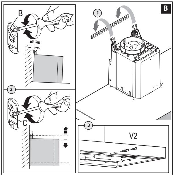
4) Drill, insert 2 ø 8mm wall plugs and fasten the support bar (S) with the relative screws (V1).
(Fig. B)
1) Hook the hood on the support bar (S).
2) Adjust the alignment of the hood, using the fixing screws.
- The upper screw (B) adjusts the distance from the wall, the lower one (C) the vertical scrolling.
3) To prevent the hood from falling due to a pressure below, fasten it to the wall with 2 ø 6mm wall plugs and relative screws (V2) using the appropriate holes on the back of the hood.
Phase 2
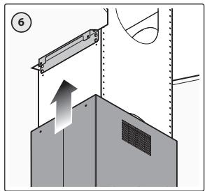
- Remove the perimeter suction panel and metallic filters as described in sec. H.
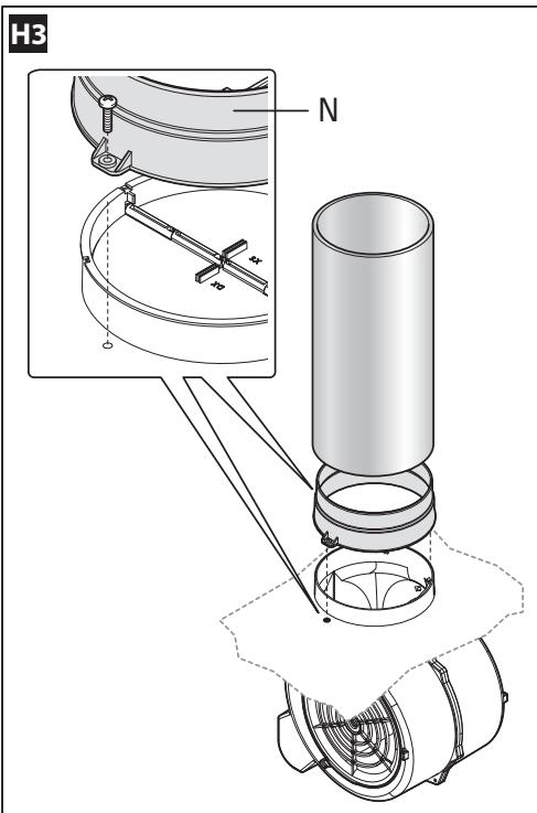
- Suction version (SUCTION MODE): install the return valve (M) as described in Fig. H2, and then, connect the outlet fitting of the fan to the external discharge through suitable piping.
- Filtering version (RECIRCULATION MODE): assemble the charcoal filters as described in sec. H.
- Carry out the electric connection only after having disconnected the electric power supply of the hood as described in sec. D.
Phase 3
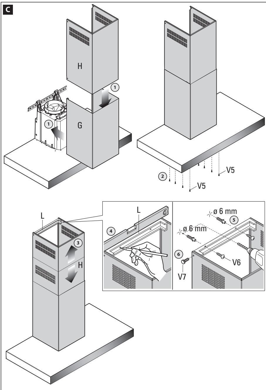
(Fig. C)
1) Insert the extension (H) in the chimney (G).
2) Fasten it all (G+H) to the hood body using the screws (V5).
3) Slide the extension (H) until it reaches the desired height.
4) Place the bracket (L) on the wall, verify the horizontal alignment with a spirit level and mark 2 drilling points at the ends.
5) Drill, insert 2 ø 6mm wall plugs and fasten the bracket (L) with the relative screws (V6).
6) Screw the extension (H) to the bracket (L) using the two screws (V7).
- Reassemble the perimeter suction panel and metallic filters as described in sec. H.
- Power the hood complying with the regulations in force (see sec. D of the booklet).
K2
ISLAND COOKER HOOD ASSEMBLY INSTRUCTIONS
Phase 1
(Fig. A1)
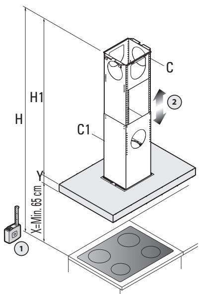
1) Identify the height H of the hob resulting from the sum of the quotas:
X + Y + H1 (X normally is equal to 65cm)
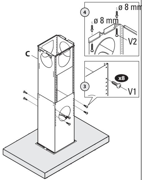
2) Scroll trellises (C) and (C1) until reaching the desired height (H),
3) Then block them using 8 self-threading screws (V1).
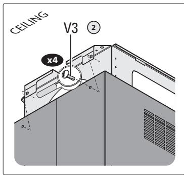
4) Fasten the trellis (C) to the ceiling with 4 ∅ 8mm wall plugs and relative screws (V2) using the appropriate holes on the ceiling.
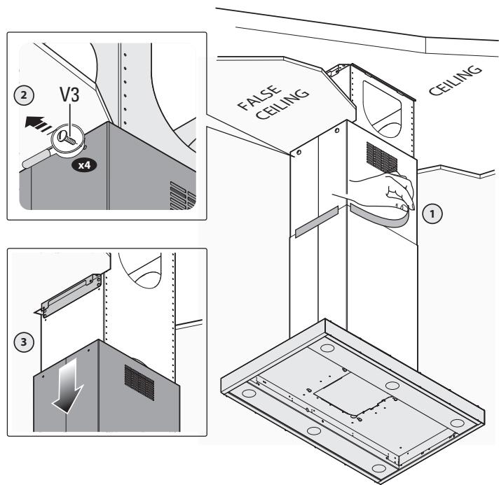
Phase 2
(Fig. B1)
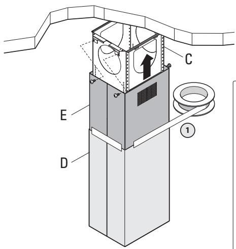
1) Introduce the extension (E) onto the chimney (D) and block them together using the adhe-
sive tape. The adhesive tape must be strong enough to bear the weight of the chimney (D), and must be adhered well in four sides.
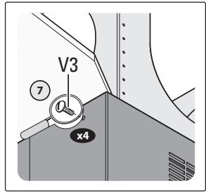
2) Fasten the chimney-extension assembly (D+E) to the trellis (C) using 4 M4 metric screws (V3) inserted in the existing holes without locking them permanently.
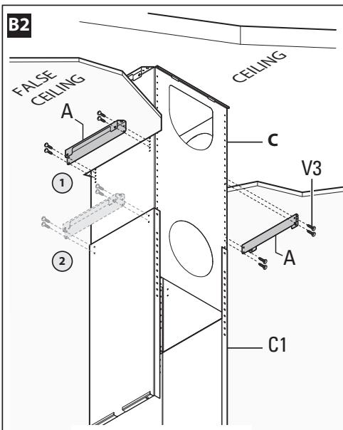
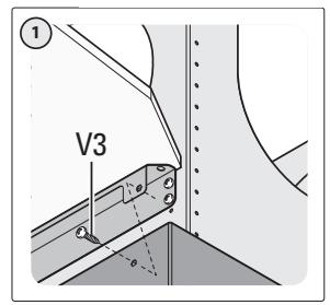
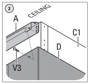
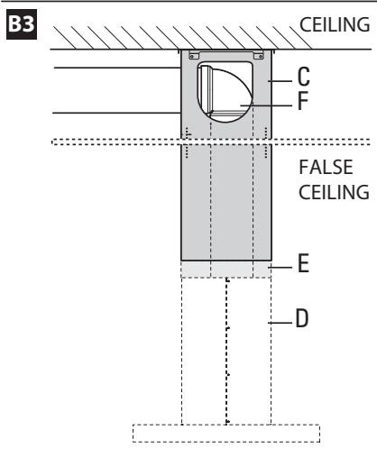
(Fig. B2) Version with false ceiling
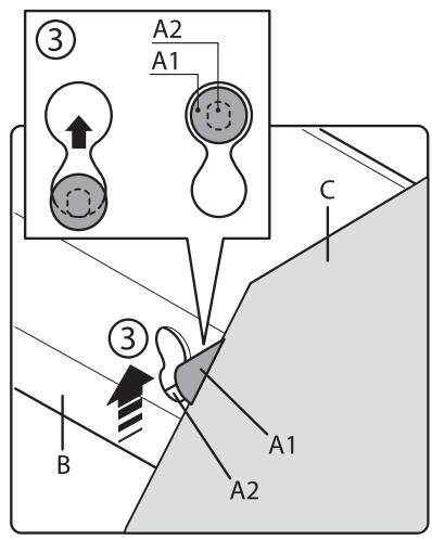
1) for false ceilings, fasten the extension support components (A) to the trellis (C) using the provided 4 screws (V3).
2) In the event the trellis (C) and the extension (D) are not used (very low ceilings and only suction version as recirculation slots of the extension are not provided), fasten the extension support elements (A) to the trellis (C1) using the 4 screws (V3).
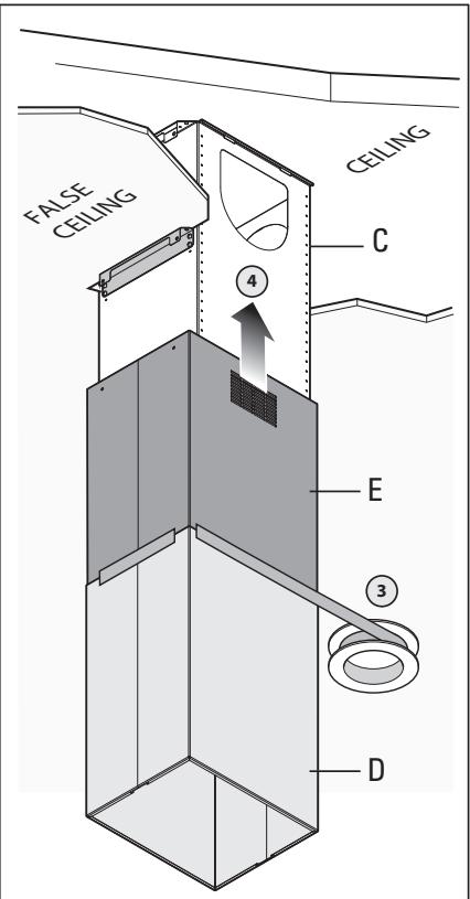
3) Insert the chimney (D) onto the extension (E) and fasten them together with the adhesive tape. The adhesive tape must be strong enough to bear the weight of the chimney (D), and must be adhered well in four sides.
4) Introduce the chimney-extension assembly (D+E) into the trellis (C).
- Fasten the chimney-extension set (D+E) to the extension support elements (A) or onto the top trellis C1 with the 4 screws (V3) without screwing them all the way.
(Fig. B3)
1) In case of suction version: install the return valve (M) and the pipe fitting (N) as described in Fig. H2 and H3. Detect the optimal height of the rigid or flexible fume discharge pipe (F) and connect it to the motor fitting.
Phase 3
(Fig. C1)
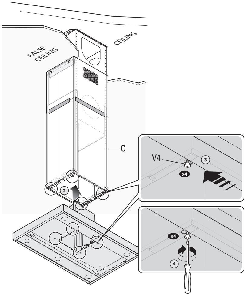
1) Remove the perimeter suction panel and metallic filters as described in sec. H.
2) Lift the cooker hood connecting it to the 4 M5 metric screws (V4) pre-tightened to the trellis (C)
3) Centre the ∅11mm holes on the slot of the interchamber and move it sideways.
4) Fasten the 4 M5 screws permanently (V4).
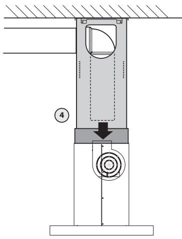
(Fig. D1)
1) Remove the adhesive tape.
2) Remove the 4 M4 metric screws (V3) previously tightened to the trellis.
3) Make the chimney-extension assembly slide downwards.
4) Connect the tube to the discharge hole of the ceiling (in case of suction version).
5) Carry out electric connection only after having disconnected the electric power supply complying with the standards in force (sec. D).
6) Make the chimney-extension assembly slide upwards.
7) Fasten the extension to the trellis (C) using the 4 M4 metric screws (V3).
8) Lock the chimney using 2 self-threaded screws (V5)
- Reassemble the perimeter suction panel and metallic filters as described in sec. H.
- Power the hood complying with the regulations in force (see sec. D of the booklet).

WARNHINWEISE

I

ÉCLAIRAGE AVEC PROJECTEURS LED
VEILIGHEIDSWAARSCHUWINGEN
CE

Check deep-fryers during use: superheated oil may be flammable.
AFDANKING VAN AFVALPRODUCTEN


LED SPOTLAMPVERLICHTING
natural_image
Symbol of a trash bin crossed with no visible text or labels


ILUMINACIÓN LED
natural_image
Symbol of a trash bin with no text or labels, crossed by two diagonal lines and a solid rectangle below (no text or symbols present)

LED SPOT BELYSNING
3. RENG∅RING AF APPARATETS YDERSIDE

natural_image
Symbol of a trash bin crossed with a diagonal line, no text or numbers presentKJ∅KKENVENTILATOR I VERSJON UTLUFTING


- Contents
- Inhalt
- SAFETY WARNINGS
- CE
- DISPOSAL OF WASTE PRODUCTS
- Information on disposal in other countries outside the European Union
- TECHNICAL SPECIFICATIONS
- INSTALLATION
- ELECTRICAL CONNECTIONS
- (Section reserved for qualified installers)
- WARNING!
- HOOD VERSION WITH EXTERNAL EXHAUST
- HOOD VERSION WITH INTERNAL RECIRCULATION (filtering)
- ELECTRONIC PUSH BUTTON CONTROL PANEL FUNCTIONING
- Key 1: Timer/Filter alarm
- Key 2: 1st Speed +On/Off motor
- Key 3: 2nd Speed
- Key 4: 3rd Speed
- Key 5: 4th Speed
- Key 6: Light
- Key pressure management
- FILTERS REMOVING AND REPLACING'S INSTRUCTIONS
- METAL FILTERS
- CARBON FILTERS
- MAINTENANCE AND CLEANING
- METAL GREASE-TRAPPING FILTERS
- CHARCOAL FILTERS
- CLEANING THE OUTSIDE OF THE APPLIANCE
- CLEANING THE INSIDE OF THE APPLIANCE
- MOUNTING HOOD INSTRUCTIONS
- K1
- WALL COOKER HOOD ASSEMBLY INSTRUCTIONS
- Phase 1
- (Fig. A)
- (Fig. B)
- Phase 2
- Phase 3
- (Fig. C)
- K2
- ISLAND COOKER HOOD ASSEMBLY INSTRUCTIONS
- (Fig. A1)
- (Fig. B1)
- (Fig. B2) Version with false ceiling
- (Fig. B3)
- (Fig. C1)
- (Fig. D1)
- WARNHINWEISE
- I
- ÉCLAIRAGE AVEC PROJECTEURS LED
- VEILIGHEIDSWAARSCHUWINGEN
- AFDANKING VAN AFVALPRODUCTEN
- LED SPOTLAMPVERLICHTING
- ILUMINACIÓN LED
- LED SPOT BELYSNING
- RENG∅RING AF APPARATETS YDERSIDE
- KJ∅KKENVENTILATOR I VERSJON UTLUFTING
Brand : PANASONIC
Model : KHB90FBC1
Category : Range hood