
FV-0511VKSL3 - Range hood PANASONIC - Free user manual and instructions
Find the device manual for free FV-0511VKSL3 PANASONIC in PDF.


| Product Type | Ventilating Fan (WhisperGreen Select®) |
| Model | FV-0511VKSL3 |
| Brand | Panasonic |
| Power Supply | 120 V, 60 Hz |
| Duct Diameter | 4 in (6 in optional) |
| Airflow (at 0.1" WG) | 50, 80, 110 CFM (selectable via Pick-A-Flow®) |
| Noise Level | < 0.3 sones |
| Fan Speed | 643 - 824 RPM (depending on CFM setting) |
| Power Consumption (Fan) | 3.9 - 10.7 W |
| Lighting | LED, 10 W (equivalent to 40-60 W incandescent) |
| Night Light | 0.1 - 1.5 W |
| Motor Type | DC motor (30-70% more efficient than ENERGY STAR minimum) |
| Weight | 10.1 lb (4.6 kg) |
| Key Features | Smart Flow™ technology, Pick-A-Flow® speed selection, Plug 'N Play™ modular components (motion, humidity, Wi-Fi), Multi-Speed module (included), Flex-Z Fast® bracket |
| Safety | GFCI protected when installed over tub/shower; do not use with solid-state speed controls |
| Maintenance | Annual cleaning; use mild detergent, avoid harsh chemicals; do not immerse motor |
| Accessories (optional) | Motion sensor (FV-MSVK1), condensation sensor (FV-CSVK1), combo sensor (FV-CMVK3), Wi-Fi module (WP100PBA) |
| Certifications | UL listed, FCC Class B, ENERGY STAR compliant |
Frequently Asked Questions - FV-0511VKSL3 PANASONIC
User questions about FV-0511VKSL3 PANASONIC
0 question about this device. Answer the ones you know or ask your own.
Ask a new question about this device
Download the instructions for your Range hood in PDF format for free! Find your manual FV-0511VKSL3 - PANASONIC and take your electronic device back in hand. On this page are published all the documents necessary for the use of your device. FV-0511VKSL3 by PANASONIC.
USER MANUAL FV-0511VKSL3 PANASONIC
INSTALLATION INSTRUCTIONS
English
Ventilating Fan
WhisperGreen Select®
Model No.
FV-0511VKSL3K
FV-0511VKSL3
FV-0511VKL3
FV-1115VKL3
Representative models:

natural_image
Technical line drawing of a mechanical ventilation system with fan and base plate (no text or symbols)FV-0511VKSL3K

natural_image
Technical line drawing of a mechanical ventilation system with fan and vent (no text or symbols)FV-0511VKL3 FV-0511VKSL3
FV-1115VKL3
Contents
IMPORTANT SAFETY INFORMATION....2-3
PLEASE READ PRIOR TO INSTALLING THIS FAN....4
DESCRIPTION....4
UNPACKING....5
SUPPLIED ACCESSORIES AND DIMENSIONS....5-6
WIRING DIAGRAM....7
FEATURES....7
INDICATIONS (Plug 'N Play™ FUNCTION DEVICES)......8-11
INSTALLATION (Plug 'N Play™ FUNCTION DEVICES)....11
INSTALLATION (CEILING MOUNTING)....12-15
INSTALLATION (WALL MOUNTING)....15-17
INSTALLATION (RETROFIT)....17-18
MAINTENANCE (CLEANING)....18-19
PRACTICAL GUIDE TO INSTALLATION....19
SPECIFICATIONS....20-21
PRODUCT SERVICE....21
READ AND SAVE THESE INSTRUCTIONS
Thank you for purchasing this Panasonic product.
Please carefully read the section "IMPORTANT SAFETY INFORMATION".
Failure to comply with instructions could result in personal injury or property damage. Please explain to users how to operate and maintain the product after installation and present this manual to users. Please retain this manual for future reference.
For your safety
To reduce the risk of injury, loss of life, electric shock, fire, malfunction, and damage to equipment or property, always observe the following safety precautions.
Explanation of symbol word panels
The following symbol word panels are used to classify and describe the level of hazard, injury, and property damage caused when the denotation is disregarded and improper use is performed.

Denotes a potential hazard that could result in serious injury or death.
Denotes a hazard that could result in minor injury.
Denotes a hazard that could result in property damage.
The following symbols are used to classify and describe the type of instructions to be observed.
| This symbol is used to alert users to a specific operating procedure that must be followed in order to operate the unit safely. | |
| This symbol is used to alert users to a specific operating procedure that must not be performed. | |
| This symbol is used to alert users not to disassemble the equipment. | |
| This symbol is used to alert users to make sure of grounding when using the equipment with the grounding terminal. |

TO REDUCE THE RISK OF FIRE, ELECTRIC SHOCK OR INJURY TO PERSONS, OBSERVE THE FOLLOWING:

Use this unit only in the manner intended by the manufacturer. If you have any questions, contact the manufacturer.

Before servicing or cleaning unit, switch power off at service panel and lock the service disconnecting means to prevent power from being switched on accidentally. When the service disconnecting means cannot be locked, securely fasten a prominent warning device, such as a tag, to the service panel.

Installation work and electrical wiring must be done by qualified person(s) in accordance with all applicable codes and standards, including fire-rated construction.

Sufficient air is needed for proper combustion and exhausting of gases through the flue (chimney) of fuel burning equipment to prevent backdraft. Follow the heating equipment manufacturer's guideline and safety standards such as those published by the National Fire Protection Association (NFPA), and the American Society for Heating, Refrigeration and Air Conditioning Engineers (ASHRAE) and the local code authorities.

When cutting or drilling into wall or ceiling, do not damage electrical wiring or other hidden utilities.

Ducted exhaust fans must always be vented to the outdoors.

If this unit is to be installed over a tub or shower, it must be marked as appropriate for the application and be connected to a GFCI (Ground Fault Circuit Interrupter) protected branch circuit.

Do not use replacement parts that have not been recommended by the manufacturer (e.g. parts made at home using 3D printer).

This product must be properly grounded.

Do not use this unit with any solid-state speed control device. Solid state controls may cause harmonic distortion which can cause a humming noise in the motor.

Not to be installed in a ceiling thermally insulated to a value greater than R60.

Do not disassemble the unit for reconstruction. It may cause fire or electric shock.

Install the fan at least 1.5 m (5 feet) above the floor.

CAUTION

Follow all local electrical and safety codes, as well as the National Electrical Code (NEC) and the Occupation Safety and Health Act (OSHA), using UL approved wire nuts.

Make sure that the electric service supply voltage is AC 120V, 60Hz.

The special-purpose or dedicated parts, such as mounting fixtures, must be used if such parts are provided.

Please wear gloves to protect hands during installation.

Do not install this ventilating fan where interior room temperature may exceed 104^ F ( 40^ C).

For general ventilating use only. Do not use to exhaust hazardous or explosive materials and vapors.

Do not kink the supply wiring.
NOTICE

Provide make up air for proper ventilation.

Do not connect multiple units in parallel. If two or more units are connected to one switch in parallel, the unit may not function.

Do not install fan above or inside 45-degree angle projected outwards from the cooking equipment element closest to fan (Fig. A).

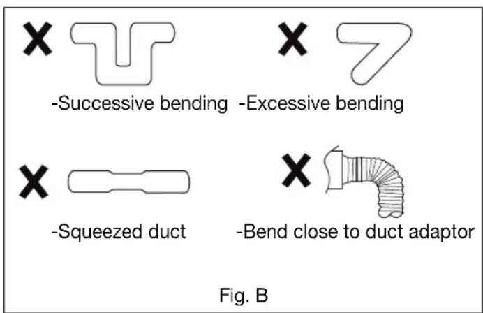
Do not install the unit where ducts are configured as shown (Fig. B).

PLEASE READ PRIOR TO INSTALLING THIS FAN
Continuous ventilation: These fans are designed to run continuously ensuring a healthy environment at low CFM levels 24 hours a day. By utilizing the optional Multi-Speed module, the fans are built to run continuously at a pre-set lower level (FV-0511VKSL3, FV-0511VKL3 and FV-0511VKSL3K: 0, 30, 40, 50, 60, 70, 80, 90, 100 CFM; FV-1115VKL3: 0, 50, 60, 70, 80, 90, 100, 110, 120 CFM). The setting is dependent on the size of the house and the individual wishes of the homeowner. It is crucial that the installer pre-sets the lower setting during the installation. Please refer to the chart below and Multi-speed module on page 8.
Custom vent Multi-Speed module (Lower Setting). ASHRAE 62.2-2022
| (sq(feet) | Two Bedrooms | Three Bedrooms | Four Bedrooms | Five Bedrooms |
| < 500 | 38 | 45 | 53 | 60 |
| 501-1000 | 53 | 60 | 68 | 75 |
| 1001-1500 | 68 | 75 | 83 | 90 |
| 1501-2000 | 83 | 90 | 98 | 105 |
| 2001-2500 | 98 | 105 | 113 | 120 |
| 2501-3000 | 113 | 120 | 128 | 135 |
| 3001-3500 | 128 | 135 | 143 | 150 |
| 3501-4000 | 143 | 150 | 158 | 165 |
| 4001-4500 | 158 | 165 | 173 | 180 |
| 4501-5000 | 173 | 180 | 188 | 195 |
Spot ventilation: These fans are also built to take care of the homeowner's spot ventilation needs when the room is occupied. The basic fan models allow a choice of three speeds. When fans are equipped with the optional Multi-Speed module, these models increase to a maximum level of 150 CFM for the FV-1115VKL3 and 110 CFM for FV-0511VKSL3, FV-0511VKL3 and FV-0511VKSL3K either when the switch is turned on, or activated by any of the following optional modules: condensation sensor (FV-CSVK1), motion sensor (FV-MSVK1) or motion + condensation sensor (FV-CMVK3).
A High/Low Delay Timer, located inside the fan unit, is utilized to return the fan back to the pre-set continuous ventilation mode. The installer needs to consult with the homeowner for the desired setting on the timer (0 - 60 minutes) and make the adjustments during the installation.
DESCRIPTION
These products are listed by UL under UL file No. E78414.
This product use a sirocco fan driven by a DC motor powered by an integral transformer. The motor is designed to have long operating life, high dynamic response, higher speed ranges and energy savings. The grille covering the fan body is a spring-attached, quick removal type. A damper for preventing air counter flow is provided. The blower uses a high-capacity sirocco fan developed to reduce the noise level. The lighting unit is an energy-saving LED device that uses a 10 W to 12.5 W LED lamp that produces almost the same illumination as a 40 W to 60 W incandescent lamp. The night light function consumes 0.1 W to 1.5 W.
TYPE IC-INHERENTLY PROTECTED.
FCC Note: This equipment has been tested and found to comply with the limits for a Class B digital device, pursuant to Part 15 of the FCC Rules. These limits are designed to provide reasonable protection against harmful interference in a residential installation. This equipment generates, uses and can radiate radio frequency energy and, if not installed and used in accordance with the instructions, may cause harmful interference to radio communications. However, there is no guarantee that interference will not occur in a particular installation. If this equipment does cause harmful interference to radio or television reception, which can be determined by turning this product on and off, the user is encouraged to try to correct the interference by one of the following measures:
- Reorient or relocate the receiving antenna.
- Increase the separation between the equipment and receiver.
- Connect equipment into outlet on a circuit different from that to which the receiver is connected.
- Consult the dealer or an experienced radio/TV technician for help.
Warning: This equipment must be installed by qualified person in accordance with the provided installation instructions; and all applicable codes and standards. Also, any changes or modifications not expressly approved by the party responsible for compliance could void the user's authority to operate this equipment.
SDoC Responsible Party:
Panasonic Corporation of North America
Two Riverfront Plaza, Newark, NJ 07102
Customer Call Support:
1-866-292-7299
This device complies with Part 15 of the FCC Rules. Operation is subject to the following two conditions: (1) This device may not cause harmful interference, and (2) this device must accept any interference received, including interference that may cause undesired operation.
Unpack and carefully remove the unit from packing.
Refer to the Supplied Accessories list to verify that all parts are present.
SUPPLIED ACCESSORIES AND DIMENSIONS
For models.- FV-0511VKSL3, FV-0511VKL3, FV-1115VKL3
| Part name | Appearance Quantity | |
| Grille |  | 1 |
| Flex-Z Fast® bracket (with 4 tapping screws -ST4.2X20) |  | 1 |
| Part name | Appearance | Quantity |
| Warranty sheet & Installation instructions | [gywt] | 1 |
| Self-drilling screw |  | 4 |
| 4 inch duct reducer (optional part), not included for FV-1115VKL3 |  | 1 |
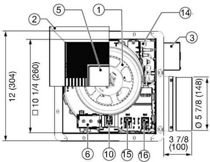


| Part name | Part nameNo No | ||
| 1 | Blade | 9 | Main PCB box |
| 2 | Grille | 10 | Pick-A-Flow® switch |
| 3 | Junction box | 11 | Fan body |
| 4 | Adapter | 12 | Damper |
| 5 | LED Lamp | 13 | Flex-Z Fast® bracket |
| 6 | Multi-Speed module (FV-0511VKSL3 only, not included in other models) | 14 | Power PCB |
| 15 | Motion sensor location (FV-MSVK1, not included), condensation sensor location (FV-CSVK1, not included) or Wi-Fi module location (WP100PBA, not included) | ||
| 7 | Connector cover | ||
| 8 | 4 Inch duct reducer (optional part), not included for FV-1115VKL3 | 16 | Motion sensor + condensation sensor (FV-CMVK3, not included ), or motion sensor (FV-MSVK1, not included), or condensation sensor |
For model.- FV-0511VKSL3K
| Part name | Appearance Quantity | |
| Grille |  | 1 |
| Flex-Z Fast® bracket (with 4 tapping screws -ST4.2X20) |  | 1 |
| Part name | Appearance | Quantity |
| Warranty sheet & Installation instructions | 1 | |
| Self-drilling screw | 4 | |
| 4 inch duct reducer (optional part) | 1 |
Unit: inches (mm)
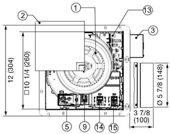

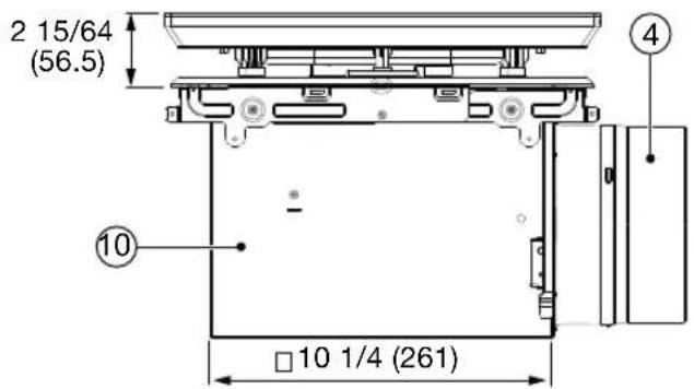


| Part name | Part nameNo No | ||
| 1 | Blade | 8 | Main PCB box |
| 2 | LED Lamp grille | 9 | Pick-A-Flow® switch |
| 3 | Junction box | 10 | Fan body |
| 4 | Adapter | 11 | Damper |
| 12 | Flex-Z Fast® bracket | ||
| 5 | Multi-Speed module | 13 | Power PCB |
| 14 | Motion sensor location (FV-MSVK1, not included),Condensation sensor location (FV-CSVK1, not included)or Wi-Fi module location (WP100PBA, not included) | ||
| 6 | Connector cover | ||
| 7 | 4 Inch duct reducer (optional part) | 15 | Motion sensor + condensation sensor (FV-CMVK3, notincluded ), or motion sensor (FV-MSVK1, not included), orcondensation sensor |

flowchart
graph TD
    A["Fan body"] --> B["DC Motor"]
    B --> C["Multi-Speed module (FV-0511VKSL3, FV-0511VKSL3K only, not included in other models)"]
    B --> D["Plug 'N Play™ module slot"]
    B --> E["Plug 'N Play™ module slot"]
    C --> F["Junction box"]
    D --> F
    E --> F
    F --> G["Black"]
    F --> H["White"]
    F --> I["Red"]
    F --> J["Red"]
    G --> K["Power switch"]
    H --> K
    I --> K
    J --> K
    K --> L["Live (Fan)"]
    K --> M["Neutral"]
    L --> N["AC120V 60Hz (Power supply)"]
    M --> O["Use signal switch for manual control of high / low CFM mode: ON to use Pick-A-Flow® setting (high speed / CFM); OFF to use Multi-speed module setting (low speed / CFM)"]
    O --> P["Do not connect the red signal wires to a live power supply (AC 120 V 60 Hz) because it will damage the product. Please use an optional switch to connect the red signal wires."]
    P --> Q["Green"]
    Q --> R["LED Lamp"]
    R --> S["Black"]
    R --> T["White"]
    R --> U["Blue"]
    S --> V["Power switch"]
    T --> V
    U --> V
    V --> W["Earth ground"]
    V --> X["Live (Light)"]
    V --> Y["Neutral"]
    V --> Z["Power switch"]
    Z --> AA["Live (Night Light)"]
    AA --> AB["AC120V 60Hz (Power supply)"]
FEATURES
Optimum ventilation performance:
Duct length, elbows and other factors increase static pressure which can hinder the performance of most ventilation fans. This fan utilizes Smart Flow microchip technology that monitors the static pressure in the system and speeds up or slows down the RPM of the fan depending upon the amount of resistance within the ducts. This feature allows the fan to perform as rated and avoid potential installation issues.
Outstanding Energy Savings:
The WhisperGreen Select ^® line of fans are built using DC motor technology. The DC motor is 30% - 70% more energy efficient than the minimum ENERGY STAR requirements.

Pick-A-Flow ^® switch
Pick-A-Flow ^® Feature
All the WhisperGreen Select ^® base models of fans come with Pick-A-Flow ^® speed options. The Pick-A-Flow ^® switch on the face of all WhisperGreen Select ^® fans allows the option to choose 50 – 80 – 110 CFM for the FV-0511VKL3, FV-0511VKSL3, FV-0511VKSL3K or 110 – 130 – 150 CFM for the FV-1115VKL3. These fans can run continuously or intermittently, depending upon the needs of the owner.
| Air volume (CFM) | Model No. Factory setting | |||
| FV-0511VKSL3FV-0511VKL3FV-0511VKSL3K | 50 | 80 | 110 | 80 CFM |
| FV-1115VKL3 | 110 | 130 | 150 | 130 CFM |
INDICATIONS (Plug 'N Play™ FUNCTION DEVICES)

Note.- There is ONLY ONE Plug 'N Play™ slot to insert the Multi-Speed module.

Note.- There are TWO Plug 'N Play™ slots to insert the condensation module.See page 11 for details.
Plug 'N Play™ Modular Component Accessories Sold Separately, Not Included With Base Model Fan
■ FV-VS15VK1 Multi-Speed module allows the fan to run continuously at lower speeds to maintain ventilation standards to meet Indoor Air Quality and then boost up to high speed to meet intermittent needs for 'Spot' or 'Point Source' exhaust needs. The FV-VS15VK1 Modular Component will operate for both the FV-0511VKL3 and the FV-1115VKL3 matching the appropriate Multi-Speed setting shown below. Multi-speed module FV-VS15VK1 is included for models FV-0511VKSL3 and FV-0511VKSL3K. It is not necessary to purchase this component. Note the options on the face of the FV-VS15VK1 Multi-Speed module to choose appropriate levels of airflow (CFM) and time delay before returning back to low speed (TIME). Choosing the Pick-A-Flow® setting automatically adjusts the Multi-Speed setting accordingly. As an example, if the Pick-A-Flow® Multi-speed setting is 80 CFM, the Multi-Speed settings adjust automatically to be 0, 30, 40, 50, 60 or 70 CFM at the lower speeds. The fan will 'boost' to the 80 CFM speed as the high speed setting. Selecting a particular TIME option will cause the fan to run for the selected amount of time before returning to the lower speed setting chosen on the CFM dial.
| Model no | Pick-A-Flow ^ (CFM) | Multi-Speed Air volume (CFM) | ||||||||
| FV-0511VKSL3, FV-0511VKL3 FV-0511VKSL3K(plug-in FV-VS15VK1) | 50 | 0 | 30 | 40 | 40 | 40 | 40 | 40 | 40 | 40 |
| 80 | 0 | 30 | 40 | 50 | 60 | 70 | 70 | 70 | 70 | |
| 110 | 0 | 30 | 40 | 50 | 60 | 70 | 80 | 90 | 100 | |
| FV-1115VKL3(plug-in FV-VS15VK1) | 110 | 0 | 50 | 60 | 70 | 80 | 90 | 100 | 100 | 100 |
| 130 | 0 | 50 | 60 | 70 | 80 | 90 | 100 | 110 | 110 | |
| 150 | 0 | 50 | 60 | 70 | 80 | 90 | 100 | 110 | 120 | |
| Delay Time (min) | 0 | 0.5 | 5 | 10 | 20 | 30 | 45 | 60 |
Factory setting: 20 minutes. Delay Time position "0": Manual wall switch control is 0 minutes; without manual wall switch control is 0.5 minutes.
■ FV-CSVK1 Condensation Sensor module turns the base fan on or boosts to higher speed when humidity is detected when used in combination with the FV-VS15VK1. The Condensation Sensor works based on calculations from the Psychrometric Chart, or combination of Relative Humidity (RH) and Temperature. This allows the fan to anticipate the formation of condensation and automatically turn ON when needed to expel humid air. The Condensation Sensor is pre-set to run for 20 minutes; it will then check the RH and Temperature to detect if the fan needs to run for another 20 minutes cycle.
This product can set air volume by Pick-A-Flow ^® switch, set humidity by the induction humidity setting switch, and operate as below.

flowchart
graph LR
    A["Power switch"] --> B["ON"]
    C["Signal switch"] --> D["ONOFF"]
    E["Condensation sensor"] --> F["Environment humidity"]
    G["Product"] --> H["Stop"]
    I["Run"] --> J["Delay operation*2"]
    K["Stop"] --> L["Run"]
    M["Stop"] --> N["Stop"]
    style E fill:#f9f,stroke:#333
    style G fill:#f9f,stroke:#333
    style I fill:#f9f,stroke:#333
    style K fill:#f9f,stroke:#333
    style M fill:#f9f,stroke:#333

Induction humidity setting switch

★ 2 The product will continue to run for about 20 minutes until it detects the environment humidity is about 5% RH lower than the humidity setting, then it will stop running.
Note:
- When the humidity sensor is used in combination with the multi-speed, the delay time can be selected as needed.
- The product will start running when the environment humidity rises rapidly (even if the humidity set point is not reached yet) and will stop after 20 minutes.
- Induction humidity setting switch is stepless change between 30 %RH \~ 80 %RH.
- The humidity detected by sensor may differ from the value on your hygrometer.
- The product may turn ON and OFF due to the unstable environment humidity, but it can be improved by adjusting the Humidity setting selector.
INDICATIONS (Plug 'N Play™ FUNCTION DEVICES)
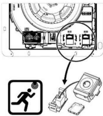
Note.- There are TWO
Plug 'N Play™ slots to insert the motion sensor module. See page 11 for detail.
■ FV-MSVK1 Motion Sensor module turns the base fan on or boosts to higher speed when motion is detected when used in combination with the FV-VS15VK1. The Motion Sensor is pre-set to run for 20 minutes; it will then re-check for movement; if detected, the fan will run for another 20 minutes cycle. The Motion Sensor detects within the range shown below.
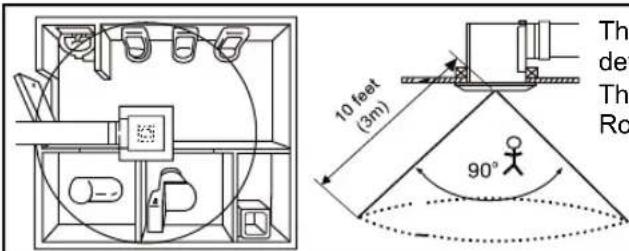
The distance that motion can be detected is limited to 10 feet (3 m). The field of view of the sensor is 90°. Room temperature is 77 °F (25 °C).


SCAN QR CODE FOR Wi-Fi
MODULE'S INSTRUCTION
OR VISIT WEB SITE
http://WP100PBA-QR.swidget.com www.swidget.com
■ WP100PBA Swidget ^® Wi-Fi control module
Wi-Fi Plug 'N Play™ features
- Wireless Plug 'N Play™ control module for Panasonic WhisperGreen Select.®
- Connect and control Panasonic ventilation products with the Swidget iOS or Android app through 2.4 GHz Wi-Fi.
- Connect, group and balance Panasonic ventilation products with a dedicated Swidget commissioning iOS or Android application through Bluetooth 5.0 mesh.
Swidget app features
- Control the boost mode of all compatible Panasonic ventilation products with an always-ON or 20-40-60 minute timer.
- Control the light module and view the motion and condensation module status of compatible Panasonic WhisperGreen Select® models.
- View the supply air and exhaust air CFM, temperature and humidity of compatible Panasonic ventilation products.
- Receive notifications for faults, filter replacement and filter cleaning for compatible Panasonic ventilation products.
- Monitor the energy consumption of compatible Panasonic ventilation products.
NOTICE
This module must only be installed and used with an approved/certified Swidget wiring device. Usage with any other devices is not permitted and will result in the warranty becoming void.
WARNING
- While not required, it is recommended to avoid any risk of shock or death, turn off power at the circuit breaker or fuse and test that the power is off before installing or removing any module.
- Not for use to control medical or life support equipment.
- For INDOOR use only: 0^ - 40^ (32°F - 104°F).
- Module can only be installed in one orientation. Rear alignment pins prevent incorrect installation. Do not forcibly install a module.
- Requires a wireless router and Internet connection for device setup.
- Double check any external Wi-Fi settings for accuracy before using them.
- Actual wireless performance in a home depends on the numbers of walls / obstacles between the module and wireless router.
INDICATIONS (Plug 'N Play™ FUNCTION DEVICES)


FV-CMVK3
Note.- There is ONLY ONE Plug 'N Play™ slot to insert the Multi-Speed module.
FV-CMVK3 (Motion sensor + Condensation sensor): This module turns the fan ON (when used by itself) or boosts it to high speed (in combination with FV-VS15VK1) when condensation OR motion are detected. Thanks to its advanced automation, the installer / user can choose the desired operation for both motion control and humidity set point. Please see table below for the different motion control selection options.
| Motion control configuration | ||||
| Motion control configuration | Motion sensor detection | Light operation | Fan operation(1) | Details |
OFF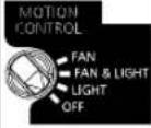 | Not detectedStep 1) | OFF OFF | - | |
Step 2) | OFF | OFF | Light must be manually turned ON from the main LED lamp switch | |
Not detectedStep 3) | OFF | OFF | Light must be manually turned OFF from the main LED lamp switch | |
LIGHT | Not detectedStep 1) | OFF | OFF | - |
DetectedStep 2) | ON | OFF | Light stays ON while motion is detected | |
Not detectedStep 3) | ON → OFF | OFF | Light will automatically turn OFF after 3 minutes | |
| FAN & LIGHTMOTIONCONTROL[FAN FAN & LIGHT LIGHT OFF] | Not detectedStep 1) | OFF | OFF | - |
DetectedStep 2) | ON | ON | Light and fan stay ON while motion is detected(1) | |
Not detectedStep 3) | ON → OFF ON → OFF | Light will automatically turn OFF after 3 minutes, and the fan after 20 minutes(1) | ||
| FANMOTIONCONTROL[FAN FAN & LIGHT LIGHT OFF] | Not detectedStep 1) | OFF | OFF | - |
DetectedStep 2) | OFF | ON | Fan stays ON while motion is detected(1), and the light must be manually turned ON from the main LED lamp switch | |
Not detectedStep 3) Outside Outside | OFF | ON →OFF | Fan will automatically turn OFF after 20 minutes, and the light must be manually turned OFF from the main LED lamp switch | |
(1) The fan operation described in the table is only related to the motion sensor detection, but the fan function also changes depending on the humidity sensor detection. For details on the operation depending on humidity settings, please refer to FV-CSVK1 at page 8 and to table "Fan operation with Plug 'N Play™ modules' combinations" at page 11.
INDICATIONS (Plug 'N Play™ FUNCTION DEVICES)
The Plug 'N Play™ modules can be used in combination, in order to adapt the fan operation to the user's needs. Please refer to the table below for details. For the LED lamp control, please refer to "Motion Control Configuration" at page 10.
| Plug 'N PlayTMmodules combination | Fan operation with Plug 'N PlayTM modules' combinations | ||
Step 1) Not detected Empty Empty | Step 2) Sensor trigger detectionMotion OR Condensation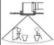  Inside Inside | Step 3) Not detectedOutside | |
 FV-MSVK1 + FV-VS15VK1 FV-MSVK1 + FV-VS15VK1 | When motion is not detected, the fan runs on low speed.(2) | Boosts the fan to high speed when motion is detected. | The fan will automatically return to low speed after the set delay time. |
 FV-CSVK1 + FV-MSVK1 FV-CSVK1 + FV-MSVK1 | When humidity is about 5% R. H. below the set point AND motion is not detected, the fan stays OFF. | Turns the fan ON for 20 minutes when motion is detected OR humidity is about 5% R. H. above the set point. | The fan will run on high speed until humidity decreases to about 5% R. H. below the set point AND 20 minutes afterwards, the fan will automatically turn OFF. |
 FV-CSVK1 + FV-VS15VK1 FV-CSVK1 + FV-VS15VK1 | When humidity is below the set point, the fan runs on low speed.(2) | Boosts the fan to high speed when humidity is about 5% R. H. above the set point. | The fan will run on high speed until humidity decreases to about 5% R. H. below the set point AND, after the set delay time has passed, it will automatically return to low speed.(2) |
 FV-CMVK3 + FV-VS15VK1 FV-CMVK3 + FV-VS15VK1 | When humidity is about 5% R. H. below the set point AND motion is not detected, the fan runs on low speed.(2) | Boosts the fan to high speed when motion is detected OR humidity is about 5% R. H. above the set point. | The fan will run on high speed until humidity decreases to about 5% R. H. below the set point AND, after the set delay time has passed, it will automatically return to low speed.(2) |
(2) When the low speed is set to 0 CFM on the multi-speed module, the fan stops running.
INSTALLATION(Plug 'N Play™ FUNCTION DEVICES)
※ You can purchase the specified Plug 'N Play™ device which are explained on page 8 through 11 and installed as described on page 11 (Fig. 2).
- Remove the corresponding connector cover (Fig. 1).
Squeeze tabs on the clasp to remove. Squeeze, insert and release the tabs on clasp to replace.

(Fig. 1)
- Plug in corresponding module to main PCB box and fix to the slot. Make sure the connector connects well (it will click when installed in place) (Fig. 2).

(Fig. 2)

WARNING
- Disconnect power supply before installing the unit.
- Please wear gloves to protect hands during the installation.
ATTENTION Remove the tape and accessory from the adapter, before installation.

1 Remove adapter plate

① Disconnect the plugs from the receptacles.
② Remove the M4X8 machine screw.
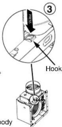
③ Press the hook and slide the adapter out of the fan body.

Install Flex-Z Fast® bracket
The Flex-Z Fast ^® bracket position can be adjusted from 16" to 24" between joists.

① Bend down 4 tabs and align bracket to the joist.
② Align and install bracket to joist by using the 2 pre-installed tapping screws.

④ 2 Tapping screws (ST4.2 X 20)
③ Extend bracket to the other joist.
④ Install bracket to joist by using 2 pre-installed tapping screws.
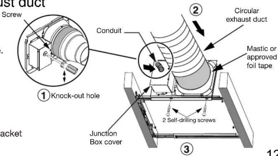
3 Install circular exhaust duct
① Remove junction box cover and secure conduit or stress relief to junction box knock-out hole.
② Install the circular exhaust duct and secure it with clamps or ties and seal it with mastic or approved foil tape. A 4 or 6 inch circular duct is needed to connect to the relevant part of the adapter.
③ Install the adapter to Flex-Z Fast ^® bracket by using 2 self-drilling screws.
4 Wiring diagram
CAUTION
- Mount junction box cover carefully so that lead wire are not pinched.

Refer to WIRING DIAGRAM (Page 7). Follow all the local electrical safety codes as well as the National Electrical Code (NEC), using UL approved wire connectors to connect fan wires.
5 Insert fan body

① Insert body and slide it into the adapter assembly until you hear a click from the hook.
6 Secure fan body
CAUTION
- Secure machine screw (M4X8) to the suitable hole and not touch the Flex-Z Fast® bracket. Please fix the screw carefully to avoid damaging the screw thread.

① When the flange overlaps the Flex-Z Fast ^® bracket, secure fan body using two self-drilling screws.
② Plug connector into receptacle and secure fan body to adapter by using machine screw (M4X8).
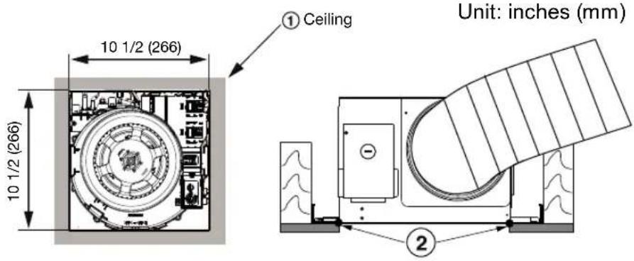
7 Sealing
① Finish ceiling work. Ceiling hole should be aligned with the inside edge of flange.
② Once fan body is mounted and secure, fill gap between flange and ceiling with caulk or other sealant to prevent air leakage.
8 Install grille
a) INSTALL GRILLE FOR MODELS FV-0511VKL3, FV-0511VKSL3, FV-1115VKL3
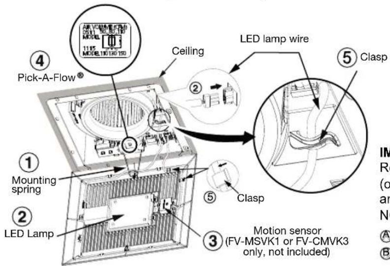
① Insert the mounting spring into the slot as shown to mount grille to fan body.
② Connect the LED lamp wire to fan body.
③ Fix the motion sensor into grille.
④ Adjust Pick-A-Flow® switch and Multi-speed selector (only models FV-0511VKSL3K, FV-0511VKSL3) as desired. Refer to indication on “FEATURES” section, page 6.
⑤ Fix the LED lamp and motion sensor cables in the indicated hooks.
⑥ Insert the other mounting spring into the slot as shown and mount grille to fan body.
CAUTION
- Before turning on the light, make sure the connector is at the correct position. If not, the lighting can't work.
- Be sure to fix the cables of the lamp and motion sensor to the hooks prior to assembling the grill.
● The claw of LED connector must latch the rib completely. - Mount grille carefully so that lead wire is not pinched.
- ATTENTION: When the switch is at the "ON" position, wait 8-10 seconds for the fan to start. This is a normal working condition.

IMPORTANT:
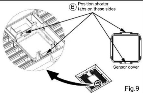
Replace the sensor cover before the installation (only for plug-in Motion sensor module FV-MSVK1 and motion sensor + condensation sensor FV-CMVK3). NOT INCLUDED (Fig. 9, and Fig. 10 on pag. 12).
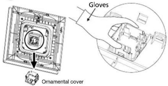
Ⓐ Keep on pressing the clasps when removing the ornamental cover.
⑧ Insert the sensor cover (attachment for FV-MSVK1, FV-CMVK3) into slot.
Ⓐ Keep on pressing the clasps when removing the ornamental cover.

INSTALLATION (CEILING MOUNTING)
b) INSTALL GRILLE FOR MODEL FV-0511VKSL3K
Note: Before Installing the grill for model FV-0511VKSL3K, follow the steps 1 through 8 (P.12 to 14).
① Insert the mounting spring into the slot as shown to mount grille to fan body.
② Connect the LED lamp wire to fan body.
③ Fix the motion sensor into grille.
④ Adjust Pick-A-Flow ^® switch and Multi-speed selector (only models FV-0511VKSL3K, FV-0511VKSL3), as desired. Refer to indication on “FEATURES” section, page 6.
⑤ Fix the LED lamp and motion sensor cables in the indicated hooks.
⑥ Insert the other mounting spring into the slot as shown and mount grille to fan body.
IMPORTANT:
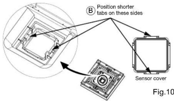
Replace the sensor cover before the installation (only for plug-in Motion sensor module FV-MSVK1 and motion sensor + condensation sensor FV-CMVK3). NOT INCLUDED (Fig. 10).

Ⓐ Keep on pressing the clasps when removing the ornamental cover.
INSTALLATION (WALL MOUNTING)

WARNING
- Disconnect power supply before installing the unit.
- Please wear gloves to protect hands during the installation.
ATTENTION
Remove the tape and accessory from the adapter, before installation.


4" reducer (Not applicable for FV-1115VKL3)

Duct tape

Remove adapter plate


① Disconnect the plugs from the receptacles.
② Remove the M4X8 machine screw.
③ Press the hook and slide the adapter out of the fan body.
2 Install Flex-Z Fast bracket
The Flex-Z Fast ^® bracket position can be adjusted from 16" to 24" between studs.


① Bend down 4 tabs and align bracket to the stud.
② Align and install bracket to stud by using 2-preinstalled tapping screws.
③ Extend bracket to the other stud.
④ Install bracket to stud by using 2-preinstalled tapping screws.
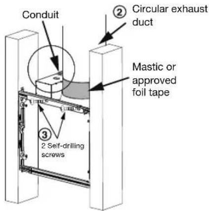
3 Install circular exhaust duct
① Remove junction box cover and secure conduit or stress relief to junction box knock-out hole.
② Install the circular exhaust duct and secure it with clamps or ties and seal it with mastic or approved foil tape. A 4 or 6 inch circular duct is needed to connect to the relevant part of the adapter.
③ Install the adapter to Flex-Z Fast ^® bracket by using 2 self-drilling screws.
④ Complete the wiring; please refer to step 4 on page 13.

CAUTION
- The adapter of product must be installed upward.
4 Insert and secure fan body


INSTALLATION (WALL MOUNTING)
① Insert the body and slide it into the adapter assembly until you hear a click from the hook.
② Secure the fan body to Flex-Z Fast® bracket by using 2 self-drilling screws.
③ Plug connector into receptacle and secure fan body to adapter by using machine screw (M4X8). To finish wall work and install grille, please refer to steps 7 and 8 (p. 14).
INSTALLATION (RETROFIT)

WARNING
- Disconnect power supply before installing the unit.
- Please wear gloves to protect hands during the installation.
ATTENTION
Remove the tape and accessory from the adapter, before installation.

1 Remove the existing fan and cut opening
Unit: inches (mm)

① Remove the existing fan, leaving the existing ductwork and wiring in place.
② Using housing masking template to mark the ceiling or wall opening, cut the ceiling or wall along the marked line.
Install Flex-Z Fast® bracket
The Flex-Z Fast ^® bracket position can be adjusted from 16" to 24" between joists or studs.

① Insert Flex-Z Fast ^® bracket.
② Align and install bracket to joist or stud by using the 2 pre-installed tapping screws.
③ Extend bracket to the other joist or stud.
④ Install bracket to joist or stud by using 2 pre-installed tapping screws.
3 Install circular exhaust duct and conduit


① Before connecting the circular duct to the adapter and conduit to junction box, pull down the circular duct and conduit from the ceiling or wall.

③ Install the circular exhaust duct and secure it with clamps or ties and seal it with mastic or approved foil tape. A 4 or 6 inch circular duct is needed to connect to the relevant part of the adapter.
④ Secure conduit and connect wires. Refer to wiring diagram on page 13.
② Before removing knock-out hole and junction box cover Following step 1 "Remove adapter plate" on (P. 12)

⑤ Install the adapter to Flex-Z Fast ^® bracket by using 2 self-drilling screws.
⑥ Finish installation process following steps 5 through 8 (P. 13 to P. 14).
1.- Routine maintenance must be done every year. Please wear gloves during the cleaning work.
2.- Never use gasoline, benzene, thinner or any other such chemicals for cleaning the ventilating fan.
3.- Do not immerse motor in water when cleaning. Do not soak resin parts in water over 140 °F (60 °C).
4.- Do not use cleaning sprays, solvent, or water on or near the sensors.
1 Remove grille
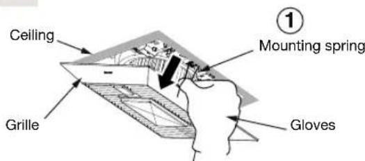
① Remove grille by pulling down one mounting spring.

WARNING
1.-Disconnect power supply before working on unit.

② Disconnect the wire from the receptacle, then pull down the other mounting spring.
2
Maintenance of unit
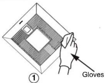

NOTE : The grille should be dry after cleaning.
① Clean grille. (Don't put into hot water. Use non-abrasive kitchen detergent, wipe dry with clean cloth.)
② Remove dust and dirt from fan body using a vacuum cleaner.
③ Using a cloth dampened with kitchen detergent, remove any dirt from fan body. Wipe dry with a clean cloth. Reinstall grille after finishing.
PRACTICAL GUIDE TO INSTALLATION
- The ducting has a strong effect on the air flow, noise and energy use of the fan. Use the shortest, straightest duct routing possible for best performance, and avoid installing the fan with smaller ducts than recommended. Insulation around the ducts can reduce energy loss and inhibit mold growth. Fans installed with existing ducts may not achieve their rated airflow.
- A circular 6-inch duct is recommended for best performance and proper fan installation.
- Ensure duct joints and exterior penetrations are sealed with caulk or other similar material to create an airtight path and to minimize building heat loss and gain and reduce the potential for condensation.
- Place / wrap insulation around duct and / or fan in order to minimize possible condensation buildup within the duct, as well as minimize building heat loss and gain.

■ Specifications for base model fans
| Model No. | Air direction | Voltage (V) | Frequency (Hz) | Duct diameter (inches) | Air volume at 0.1" WG (CFM) | Noise (sones) | Speed (rpm) | Power (W) | Weight lb. (kg) | |
| Fan | Lighting / Night Light | |||||||||
| FV-0511VKSL3 | Exhaust | 120 | 60 | 4 | <0.3 | 824110 | 10.5 | 10 / 0.2 | 10.1 (4.6) | |
| FV-0511VKL3 | 80 | <0.3 | 722 | 6.4 | ||||||
| 50 | <0.3 | 643 | 3.9 | |||||||
| FV-0511VKSL3K | Exhaust | 120 | 60 | 4 | 110 | <0.3 | 834 | 10.7 | 12.5 / 1.5 | 11.7 (5.3) |
| 80 | <0.3 | 735 | 6.4 | |||||||
| 50 | <0.3 | 628 | 3.9 | |||||||
| Model No. | Air direction | Voltage (V) | Frequency (Hz) | Duct diameter (inches) | Air volume at 0.1" WG (CFM) | Noise (sones) | Speed (rpm) | Power (W) | Weight lb. (kg) | |
| Fan | Lighting / Night Light | |||||||||
| FV-0511VKSL3FV-0511VKL3 | Exhaust | 120 | 60 | 6 | <0.3 | 636110 | 7.2 | 10 / 0.2 | 10.1(4.6) | |
| 80 | <0.3 | 591 | 4.6 | |||||||
| 50 | <0.3 | 587 | 3.5 | |||||||
| FV-0511VKSL3K | Exhaust | 120 | 60 | 6 | 110 | <0.3 | 644 | 7.1 | 12.5 / 1.5 | 11.7 (5.3) |
| 80 | <0.3 | 608 | 4.8 | |||||||
| 50 | <0.3 | 610 | 3.7 | |||||||
| FV-1115VKL3 | Exhaust | 120 | 60 | 6 | 150 | 0.4 | 724 | 12.6 | 10 / 0.2 | 9.9 (4.5) |
| 130 | <0.3 | 681 | 9.7 | |||||||
| 110 | <0.3 | 636 | 7.2 | |||||||
Performance based on HVI procedures 915, 916 and 920
■ Specifications for Multi-Speed fans
| Model No. | Air direction | Voltage (V) | Frequency (Hz) | Duct diameter (inches) | Air volume at 0.1" WG (CFM) | Noise (sones) | Speed (rpm) | Power (W) | Weight lb. (kg) | |
| Fan | Lighting / Night Light | |||||||||
| FV-0511VKSL3 FV-0511VKL3 | Exhaust | 60120 | 4 | 100 | <0.3 | 793 | 8.6 | 10 / 0.2 | 10.1 (4.6) | |
| 90 | <0.3 | 754 | 7.2 | |||||||
| 80 | <0.3 | 722 | 6.4 | |||||||
| 70 | <0.3 | 693 | 5.3 | |||||||
| 60 | <0.3 | 672 | 4.7 | |||||||
| 50 | <0.3 | 643 | 3.9 | |||||||
| 40 | <0.3 | 628 | 3.5 | |||||||
| 30 | <0.3 | 623 | 3.1 | |||||||
| 0 | - | - | 1.0 (*) | |||||||
| FV-0511VKSL3K | Exhaust | 120 | 60 | 100 | <0.3 | 801 | 8.7 | 12.5 / 1.5 | 11.7 (5.3) | |
| 90 | <0.3 | 759 | 7.2 | |||||||
| 80 | <0.3 | 735 | 6.4 | |||||||
| 70 | <0.3 | 712 | 5.6 | |||||||
| 60 | <0.3 | 675 | 4.6 | |||||||
| 50 | <0.3 | 628 | 3.9 | |||||||
| 40 | <0.3 | 612 | 3.4 | |||||||
| 30 | <0.3 | 605 | 2.9 | |||||||
| 0 | - | - | 1.0 (*) | |||||||
| Model No. | Air direction | Voltage (V) | Frequency (Hz) | Duct diameter (inches) | Air volume at 0.1" WG (CFM) | Noise (sones) | Speed (rpm) | Power (W) | Weight lb. (kg) | |
| Fan | Lighting / Night Light | |||||||||
| FV-0511VKSL3 FV-0511VKL3 | Exhaust | 120 | 60 | 6 | 100 | <0.3 | 621 | 6.0 | 10 / 0.2 | 10.1 (4.6) |
| 90 | <0.3 | 605 | 5.3 | |||||||
| 80 | <0.3 | 591 | 4.6 | |||||||
| 70 | <0.3 | 588 | 4.2 | |||||||
| 60 | <0.3 | 595 | 3.9 | |||||||
| 50 | <0.3 | 587 | 3.5 | |||||||
| 40 | <0.3 | 586 | 3.2 | |||||||
| 30 | <0.3 | 595 | 2.9 | |||||||
| 0 | - | - | 1.0 (*) | |||||||
| FV-0511VKSL3K | Exhaust | 120 | 60 | 100 | <0.3 | 621 | 6.1 | 12.5 / 1.5 | 11.7 (5.3) | |
| 90 | <0.3 | 614 | 5.5 | |||||||
| 80 | <0.3 | 608 | 4.8 | |||||||
| 70 | <0.3 | 610 | 4.5 | |||||||
| 60 | <0.3 | 611 | 4.0 | |||||||
| 50 | <0.3 | 610 | 3.7 | |||||||
| 40 | <0.3 | 589 | 3.2 | |||||||
| 30 | <0.3 | 599 | 3.0 | |||||||
| 0 | - | - | 1.0 (*) | |||||||
| FV-1115VKL3 | Exhaust | 120 60 | 4 | 120 | <0.3 | 660 | 8.1 | 10 / 0.2 9 | 9 / (4.5) | |
| 110 | <0.3 | 636 | 7.2 | |||||||
| 100 | <0.3 | 621 | 6.0 | |||||||
| 90 | <0.3 | 605 | 5.3 | |||||||
| 80 | <0.3 | 591 | 4.6 | |||||||
| 70 | <0.3 | 588 | 4.2 | |||||||
| 60 | <0.3 | 595 | 3.9 | |||||||
| 50 | <0.3 | 587 | 3.5 | |||||||
| 0 | - | - | 1.0(*) | |||||||
Reference performance based on HVI procedures 915, 916 and 920. [ (*) Stand by wattage)
PRODUCT SERVICE
Warning Concerning Removal of Covers. The unit should be serviced by qualified technicians only. Your product is designed and manufactured to ensure a minimum of maintenance. Should your unit require service or parts, call Panasonic Call Center at 1-866-292-7299 (USA) or 1-800-669-5165 (Canada).
Panasonic Corporation of North America
Two Riverfront Plaza, Newark, NJ 07102
www.panasonic.com
Panasonic Canada Inc.
5770 Ambler Drive, Mississauga, Ontario L4W 2T3 www.panasonic.ca


- INSTALLATION INSTRUCTIONS
- WhisperGreen Select®
- Contents
- READ AND SAVE THESE INSTRUCTIONS
- For your safety
- Explanation of symbol word panels
- TO REDUCE THE RISK OF FIRE, ELECTRIC SHOCK OR INJURY TO PERSONS, OBSERVE THE FOLLOWING:
- CAUTION
- NOTICE
- PLEASE READ PRIOR TO INSTALLING THIS FAN
- DESCRIPTION
- SUPPLIED ACCESSORIES AND DIMENSIONS
- FEATURES
- Optimum ventilation performance:
- Outstanding Energy Savings:
- INDICATIONS (Plug 'N Play™ FUNCTION DEVICES)
- Plug 'N Play™ Modular Component Accessories Sold Separately, Not Included With Base Model Fan
- WARNING
- INSTALLATION(Plug 'N Play™ FUNCTION DEVICES)
- Remove adapter plate
- Install Flex-Z Fast® bracket
- Install circular exhaust duct
- Wiring diagram
- Insert fan body
- Secure fan body
- Sealing
- Install grille
- IMPORTANT:
- INSTALLATION (CEILING MOUNTING)
- INSTALLATION (WALL MOUNTING)
- Remove adapter plate
- Install Flex-Z Fast bracket
- Insert and secure fan body
- INSTALLATION (RETROFIT)
- Remove the existing fan and cut opening
- Install circular exhaust duct and conduit
- Remove grille
- 2
- Maintenance of unit
- PRACTICAL GUIDE TO INSTALLATION
- PRODUCT SERVICE
Brand : PANASONIC
Model : FV-0511VKSL3
Category : Range hood