
KHAX95XB - Range hood PANASONIC - Free user manual and instructions
Find the device manual for free KHAX95XB PANASONIC in PDF.
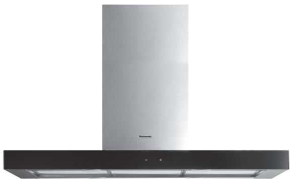
| Product type | Range hood |
| Brand | Panasonic |
| Model | KH-AX95XB |
| Power supply | 220-240 V ~ 50 Hz |
| Dimensions without chimney (W x D x H) | 898 x 580 x 60 mm |
| Adjustable chimney height | 730 - 1000 mm |
| Unpacked weight (approx.) | 25 kg |
| Version | Island |
| Number of speeds | 3 + intensive mode |
| Exhaust type | Exhaust or recirculation (optional charcoal filter) |
| Air outlet diameter | 150 mm (reducible to 120 mm) |
| Lighting | Integrated (replaceable) |
| Cleaning of grease filters | Every 2 months, dishwasher safe |
| Charcoal filter replacement | Every 4 months (non-reusable) |
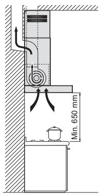
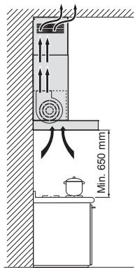
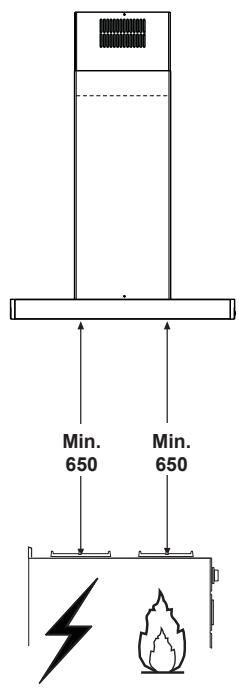
| Safety distance between hob and hood | At least 650 mm |
| Material | Metal (body) and glass? (not specified, estimation) |
| Color | Not specified |
| Installation | Island (ceiling/shelf) or wall-mounted (TX95GB and TX65CB models) |
| Warranty | Not specified |
| Available spare parts | Charcoal filters, grease filters, lighting unit |
| Product code | KH-AX95XBEPG |
Frequently Asked Questions - KHAX95XB PANASONIC
User questions about KHAX95XB PANASONIC
0 question about this device. Answer the ones you know or ask your own.
Ask a new question about this device
Download the instructions for your Range hood in PDF format for free! Find your manual KHAX95XB - PANASONIC and take your electronic device back in hand. On this page are published all the documents necessary for the use of your device. KHAX95XB by PANASONIC.
USER MANUAL KHAX95XB PANASONIC
Model No. KH-AX95XB KH-TX95GB KH-TX65CB
KH-AX95XB
IMPORTANT SAFETY INSTRUCTIONS: Before operating this appliance, please read these instructions carefully and keep for future reference.
Operating Instructions 2-8
Safety Instructions 2-4
Energy Saving Tips. 4
Disposal of Waste Products 5
Modes of Extraction 5
Features and Functions. 6
Maintenance and Cleaning. 7-8
- Cleaning Metal Grease Filters .......7
- Replacing Optional Charcoal Filter (Recirculation Mode) 8
- Lighting Unit 8
Installation Instructions. 9-25
Installation and Connection 9
Safety Instructions. 9-11
Extractor Hood Parts. 12-15
-Island KH-AX95XB. 12-13
- Wall Mounted KH-TX95GB/ KH-TX65CB. 14-15
Dimensions 16-18
-Island KH-AX95XB. 16
- Wall Mounted KH-TX95GB 17
- Wall Mounted KH-TX65CB............18
Installing the Appliance. 19-24
- Island
Drilling the Ceiling / Wooden Shelf 19
Fixing the Frame. 20
- Wall Mounted
■ Wall Drilling and Bracket Fixing – Wall Marking. 21
Mounting the Hood Body. 22
- Island and Wall Mounted
Ducted Mode Air Exhaust System. 22
Recirculation Mode Air Outlet....23
-Island
Application of Novastick Tape....23
Fitting the Panel and Fixing the Hood Canopy. 24
- Wall Mounted
Upper Chimney Assembly...25
Lower Chimney Assembly.....25
Specifications. 26
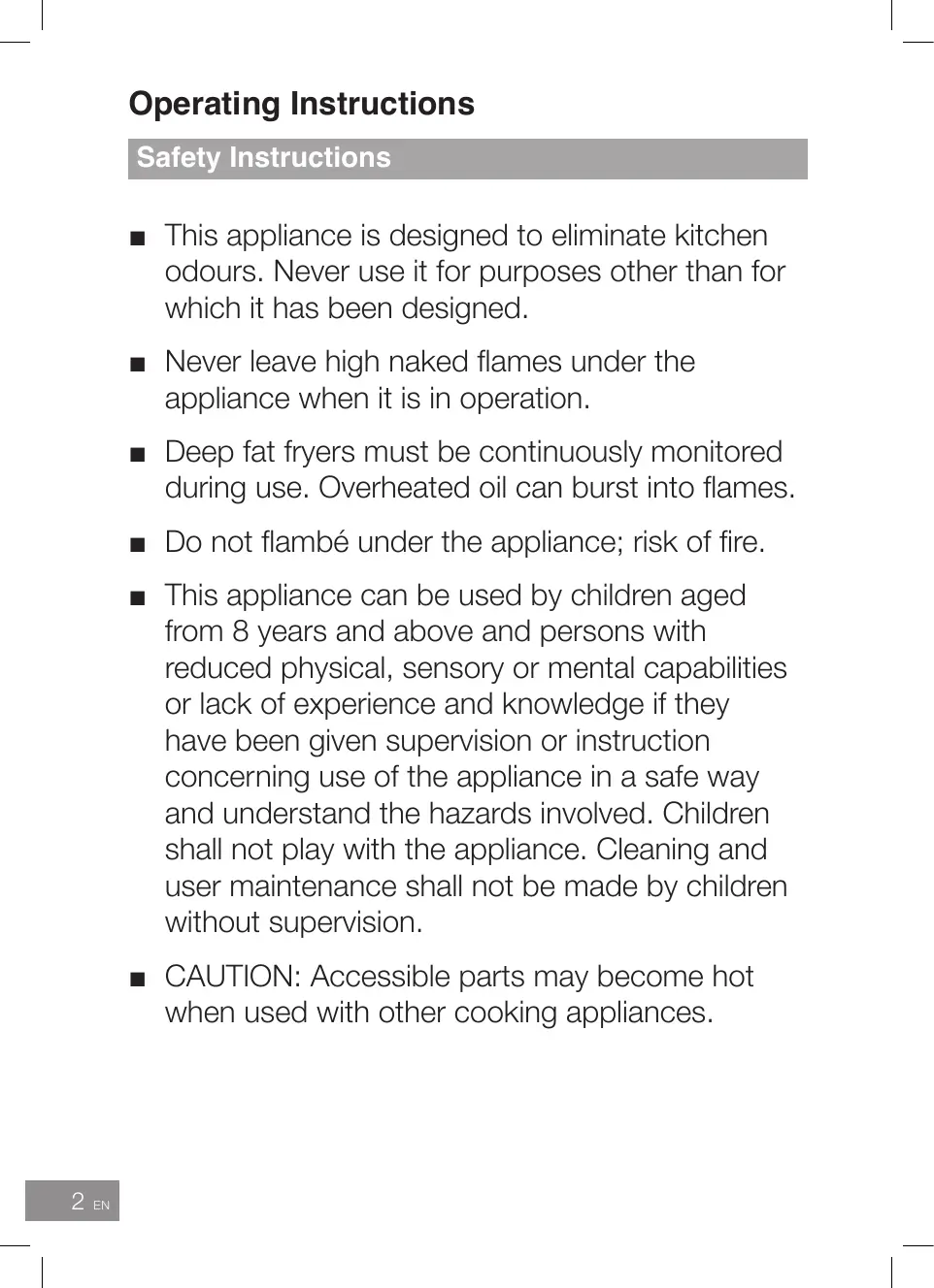
Operating Instructions
Safety Instructions
This appliance is designed to eliminate kitchen odours. Never use it for purposes other than for which it has been designed.
- Never leave high naked flames under the appliance when it is in operation.
- Deep fat fryers must be continuously monitored during use. Overheated oil can burst into flames.
- Do not flâbé under the appliance; risk of fire.
This appliance can be used by children aged from 8 years and above and persons with reduced physical, sensory or mental capabilities or lack of experience and knowledge if they have been given supervision or instruction concerning use of the appliance in a safe way and understand the hazards involved. Children shall not play with the appliance. Cleaning and user maintenance shall not be made by children without supervision.
CAUTION: Accessible parts may become hot when used with other cooking appliances.
Safety Instructions
- Switch off or unplug the appliance from the mains supply before carrying out any maintenance work.
- Clean and/or replace the filters after the specified time period; risk of fire. See pages 7-8.
Clean the appliance using a damp cloth and a neutral liquid detergent.
WARNING: In case of malfunction or breakdown, immediately stop using the appliance. Turn off the main power switch and the circuit breaker, and then contact the service centre. Failure to do this may cause smoke, burns, and electric shock.
If the power cord is damaged, it must be replaced by the manufacturer or a service technician authorised by the manufacturer in order to avoid a hazard. Do not disassemble, repair, or modify the appliance. For repairs, contact the dealer where you purchased the appliance.
WARNING: This appliance must be earthed to prevent electric shock or fire. - Do not use a steam cleaner.
Safety Instructions
- The appliance is not intended to be operated by means of an external timer or separate remote control system.
WARNING: The manufacturer cannot be held liable for damage to persons or items caused by failure to observe the safety instructions, by interference with any part of the appliance or by the use of non- original spare parts.
Energy Saving Tips
Do not use a higher fan speed than necessary.
- Do not use the extractor hood unless you are cooking.
- Do not use the hood lighting for longer than necessary.
- Clean grease filters regularly to improve airflow. This will allow the appliance to work more efficiently and clear odours quickly.
Disposal of Waste Products
Information on Disposal for Users of Waste Electrical & Electronic Equipment (private households)
This symbol on the products and/or accompanying documents means that used electrical and electronic products should not be mixed with general household waste.
For proper treatment, recovery and recycling, please take these products to designated collection points, where they will be accepted on a free of charge basis. Alternatively, in some countries you may be able to return your products to your local retailer upon the purchase of an equivalent new product.
Disposing of this product correctly will help to save valuable resources and prevent any potential negative effects on human health and the environment
which could otherwise arise from inappropriate waste handling. Please contact your local authority for further details of your nearest designated collection point.
Penalties may be applicable for incorrect disposal of this waste, in accordance with national legislation.
Information on Disposal in other Countries outside the European Union
This symbol is only valid in the European Union.
If you wish to discard this product, please contact your local authorities or dealer and ask for the correct method of disposal.
Modes of Extraction
Ducted Mode
Recirculation Mode
Control Panel


Main Power off

Activates Fan Power 1 ( A + B will be illuminated.)

Activates Fan Power 2 ( A + C will be illuminated.)

Timer - Press and hold ⑨ for 2 seconds to activate the timer. ( A will be illuminated and C will flash.) Main Power and the lighting will automatically switch off after 30 minutes.

Activates Fan Power 3 ( A + D will be illuminated.)

Boost - To activate Boost, press and hold D for 2 seconds. (A will be illuminated and D will flash.) To remove heavy cooking fumes, the fan will run at high speed for approx. 5 minutes before returning to the previous fan speed.

Lighting On/Off (When switched on, E will be illuminated.)

CAUTION
Before cleaning, turn off the main power switch.
- Do not use a steam cleaner. Water may get into the electrical components and cause damage.
- During the warranty period, any repairs may only be performed by service technicians authorised by the appliance manufacturer.
- Unauthorised repairs may cause electric shock and short circuit; do not attempt this yourself. Consult an authorised service technician.

NOTE
A visit by a service technician during the warranty period will be charged if the appliance is not functioning because of improper use. Store these instructions in a place where they are always readily accessible; if passing the appliance on to another person, the instructions should also be included.
Always keep the appliance in a clean condition. Built up grease on the appliance may become difficult to clean.
Grease Stains
Wipe off with a damp cloth and mild detergent.
- Do not use strong acidic or alkaline detergents, such as bleach or synthetic detergents. They may cause discolouration.
Cleaning Metal Grease Filters
The filters must be cleaned every 2 months, or more frequently for heavy use.
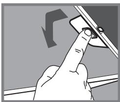
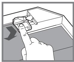
- Remove the filters one at a time by pushing them backwards and downwards at the same time.
- Wash the filters, taking care not to bend them.
- When refitting the filters, make sure that they are dry and that the handle is on the outside.
The filters are dishwasher safe.
Replacing Optional Charcoal Filter (Recirculation Mode)
The filter must be replaced every 4 months, or more frequently for heavy use. The filter cannot be reused.
Remove the metal grease filters.
- Remove the charcoal filter by releasing the fixing hooks.
Fit the new filter by hooking it into its seating.
Refit the metal grease filters.
Lighting Unit
For replacement contact the service centre.

NOTE
Charcoal filter is available from the service centre.
Please fully observe the following safety precautions.

IMPORTANT
- Unpack the appliance, remove all packing material, and examine for any damage. If the appliance is damaged DO NOT install and notify your dealer immediately.
Install the appliance in accordance with the Installation Instructions. Otherwise, the performance of the appliance may be affected.
■ After installation perform a test run and explain to the customer how to operate the appliance. - Correct installation is the responsibility of the installer. Any malfunction or accident resulting from the failure to follow the Installation Instructions is not covered by the warranty.
Safety Instructions
The manufacturer will not be held liable for any damages resulting from improper installation.
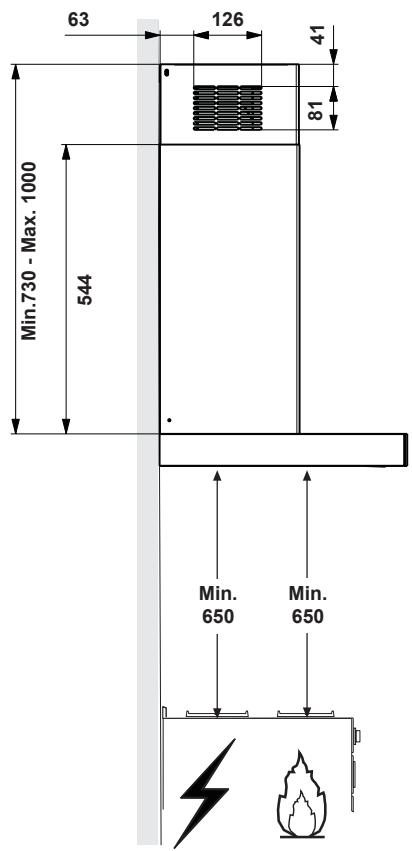
- The minimum safety distance between the cooker top and this appliance is 650~mm . (If the instructions for installation of a gas hob specify a greater distance, this has to be taken into account).
Safety Instructions
- Check that the mains voltage corresponds to that indicated on the rating plate fixed to the inside of the appliance (remove grease filter to access the rating plate).
- Check that the domestic power supply guarantees adequate earthing. Connect the extractor to the exhaust flue through a pipe of minimum diameter 120 ~mm . The route of the flue must be as short as possible.
- Do not connect the appliance to exhaust ducts carrying combustion fumes (e.g. boilers, fireplaces, etc.).
- There shall be adequate ventilation of the room when this appliance is used at the same time as other appliances burning gas or other fuels (not applicable to appliances that only discharge the air back into the room). When this appliance is used in conjunction with other appliances supplied with energy other than electric, the negative pressure in the room must not exceed 4 × 10^-5 bar to prevent fumes being drawn back into the room.
Safety Instructions
In the event of damage to the power cord, it must be replaced by a service technician authorised by the manufacturer, in order to prevent any risks.
Regulations concerning the discharge of air have to be fulfilled.
- When this appliance is installed, it should be easy to isolate the appliance from the electricity supply by operating a circuit breaker or disconnecting from the mains.
- DO NOT use multi-plug adaptors, power strips or extension leads. There is a risk of fire in the event of overloading.
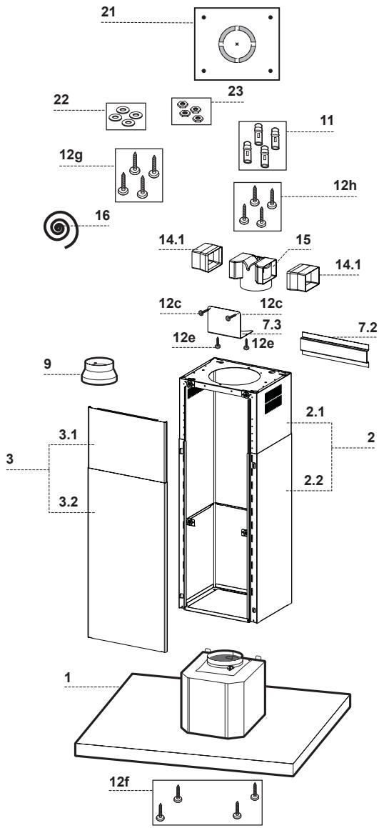
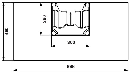
Island KH-AX95XB
Island KH-AX95XB
| Ref. | Qty | Product Components |
| 1 | 1 | Hood body with controls, light, blower, filters |
| 2 | Telescopic chimney unit | |
| 2.1 | 1 | Telescopic chimney - upper section |
| 2.2 | 1 | Telescopic chimney - lower section |
| 3 | Telescopic panel | |
| 3.1 | 1 | Telescopic panel - upper panel |
| 3.2 | 1 | Telescopic panel - lower panel |
| 9 | 1 | Reducer flange ø 150-120 mm |
| 14.1 | 2 | Air outlet connector extension |
| 15 | 1 | Air outlet connector |
| 16 | 1 | Novastick tape |
| Ref. | Qty | Installation Components |
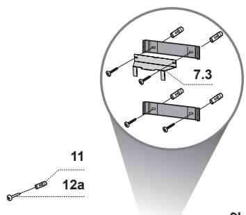
| 7.3 | 1 | Air outlet connector fixing bracket |
| 7.2 | 1 | Telescopic chimney fixing bracket |
| 11 | 4 | Wall plugs ø 10 |
| 12c | 2 | Screws 2.9 x 6.5 mm |
| 12e | 2 | Screws 2.9 x 9.5 mm |
| 12f | 4 | Screws M4 x 80 mm |
| 12g | 4 | Screws M6 x 15 mm |
| 12h | 4 | Screws 5.2 x 70 mm |
| 21 | 1 | Drilling template |
| 22 | 4 | Washers ø 6.4 mm |
| 23 | 4 | Nuts M6 |
Wall Mounted KH-TX95GB / KH-TX65CB
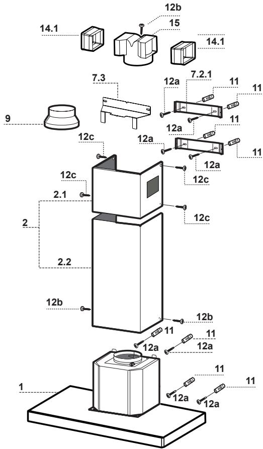
Wall Mounted KH-TX95GB / KH-TX65CB
| Ref. | Qty | Product Components |
| 1 | 1 | Hood body with controls, light, blower, filters |
| 2 | Telescopic chimney unit | |
| 2.1 | 1 | Telescopic chimney - upper section |
| 2.2 | 1 | Telescopic chimney - lower section |
| 9 | 1 | Reducer flange ø 150-120 mm |
| 14.1 | 2 | Air outlet connector extension |
| 15 | 1 | Air outlet connector |
| Ref. | Qty | Installation Components |
| 7.2.1 | 2 | Upper chimney section fixing brackets |
| 7.3 | 1 | Air outlet connector fixing bracket |
| 11 | 8 | Wall plugs |
| 12a | 8 | Screws 4.2 x 44.4 mm |
| 12b | 3 | Screws 2.9 x 9.5 mm |
| 12c | 4 | Countersunk screws 2.9 x 9.5 mm |
Island KH-AX95XB
(measurement: mm)
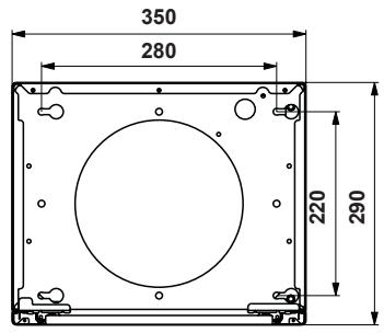
Top View
Side View
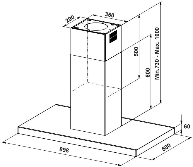
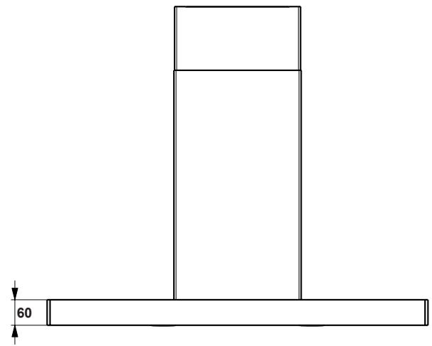
Front View

WARNING
If the instructions for installation of a gas hob specify a greater distance, this has to be taken into account.
Wall Mounted KH-TX95GB
(measurement: mm)
Top View
Side View
Front View

WARNING
If the instructions for installation of a gas hob specify a greater distance, this has to be taken into account.
Wall Mounted KH-TX65CB
(measurement: mm)
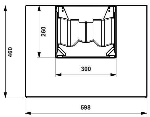
Top View
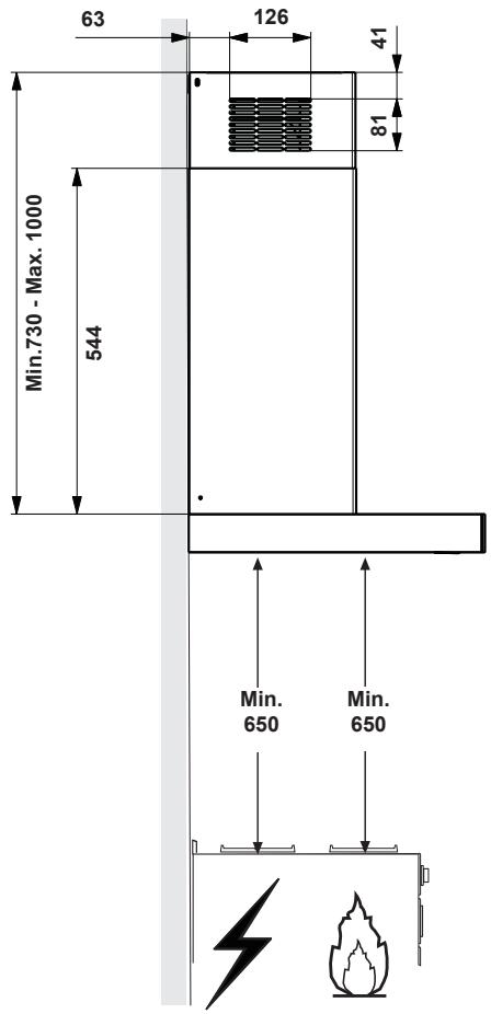
Side View
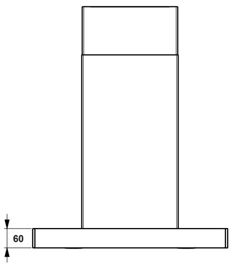
Front View

WARNING
If the instructions for installation of a gas hob specify a greater distance, this has to be taken into account.
Island
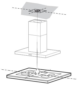
Drilling the Ceiling / Wooden Shelf
Use a plumb line to mark the centre of the hob on the ceiling/wooden shelf.
- Place the drilling template (Ref. 21) provided on the ceiling/wooden shelf, making sure that the template is in the correct position by lining up the axes of the template with those of the hob.
Mark the centres of the holes in the template.
Drill the holes at the points marked:
- For concrete ceilings, drill for plugs appropriate to the screw size.
- For hollow brick ceilings with wall thickness of 20mm : drill 10mm and immediately insert the wall plugs (Ref. 11) supplied.
- For wooden beam ceilings, drill according to the wood screws used.
- For wooden shelf, drill 7 mm .
- For the power supply cable feed, drill 0.10mm
-
For the air outlet of ducted mode, drill according to the diameter of the external air exhaust duct connection.
-
Insert 2 screws diagonally from each other with a 4 - 5mm gap from the ceiling/wooden shelf. Insert the remaining 2 screws ensuring the gap is maintained.
-
For concrete ceilings, use the appropriate plugs for the screw size (not provided). For cavity ceiling with inner space, with wall thickness of approx. 20mm , use the screws (Ref. 12h), supplied.
- For wooden beam ceilings, use 4 wood screws (not provided).
- For wooden shelf, use the 4 screws (Ref. 12g) with the washers (Ref. 22) and the nuts (Ref. 23), provided.

WARNING
The ceiling must be flat, horizontal and be able to bear the load. The wall plugs must have a secure grip. The enclosed screws and wall plugs are suitable for solid brickwork or solid concrete. Suitable fasteners must be used for other structures (e.g. plasterboard, porous concrete, porous bricks).
Island
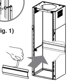
(fig.1)
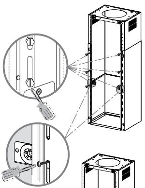
Fixing the Frame
Should it be necessary to adjust the height of the frame, proceed as follows:
- Unfasten the metric screws joining the two opposite parts that can be seen from the front.
- Adjust the height of the frame as required, then replace the screws removed as above, making sure that you insert 2 of them close to the panel connector (fig. 1).
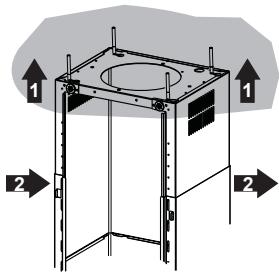
- Lift the frame, insert the slots onto the screws and slide them until they lock.
- Tighten the two screws and insert the other two screws provided.
Take the telescopic chimney fixing bracket (Ref. 7.2), remove the film from the double sided adhesive and fix it inside the frame so as to hold it more firmly.
Before final locking of the screws it is possible to make small adjustments to the frame, making sure that the screws do not come out of the adjustment slot.
- The frame must be securely fastened both due to the weight of the appliance and the stress caused by occasional sideways pressure when in position. When fastened, check that the base is stable even when the frame is subjected to bending.
In all cases where the ceiling is not sufficiently strong at the point of suspension, the installer must strengthen it with suitable plates and counterplates, anchored to structurally sound elements.
Wall Mounted
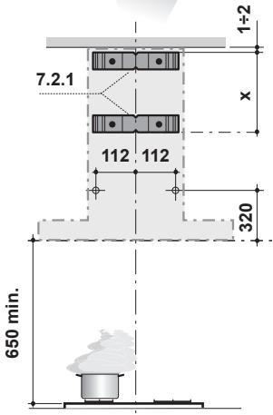
Wall Drilling and Bracket Fixing - Wall Marking:
Draw a vertical line on the supporting wall up to the ceiling, or as high as practical, at the centre of the area in which the hood will be installed.
Draw a horizontal line at 650mm above the hob.
- Place the bracket (Ref. 7.2.1) on the wall as shown about 1 - 2mm from the ceiling or upper limit aligning the centre (notch) with the vertical reference line.
- Mark the wall at the centres of the holes in the bracket.
- Place another bracket (Ref. 7.2.1) on the wall as shown at X mm below the first bracket (X = height of the upper chimney section supplied), aligning the centre (notch) with the vertical line.
- Mark the wall at the centres of the holes in the brackets.
- Mark a reference point as indicated at 112mm from the vertical reference line and 320mm above the horizontal reference line.
Repeat this operation on the other side.
- Drill 8 mm holes at all the centre points marked.
Insert the wall plugs (Ref. 11) in the holes.
Fix the lower bracket (Ref. 7.2.1) using the 2 screws (Ref. 12a) supplied.
Fix the upper bracket (Ref. 7.2.1) and the air outlet connection support (Ref. 7.3) together using the 2 screws (Ref.12a) supplied.
- Insert the 2 screws (Ref.12a) supplied in the hood body fixing holes, leaving a gap of 5 - 6mm between the wall and the head of the screw.
Wall Mounted
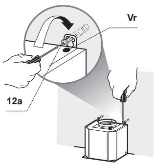
Mounting the Hood Body
Before attaching the hood body, tighten the two screws Vr located on the hood body mounting points.
■ Hook the hood body on to the screws (Ref.12a).
Fully tighten the support screws (Ref.12a).
Adjust the screws (Ref. Vr) to level the hood body.
If necessary, it is possible to fasten the appliance to the wall using more screws with wall plugs, which can be positioned from inside the hood canopy.
Island and Wall Mounted
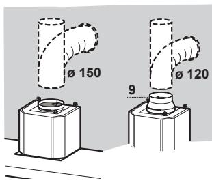
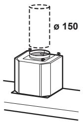
Ducted Mode Air Exhaust System
When installing the ducted mode, connect the hood to the chimney using either a flexible or rigid pipe 150 or 120~mm , the choice of which is left to the installer.
To install a 0.120mm air exhaust connection, insert the reducer flange (Ref. 9) on the hood body outlet.
Fix the pipe in position using sufficient pipe clamps (not supplied).
Remove charcoal filters if present.
Island and Wall Mounted
Island
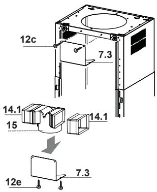
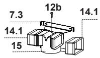
Recirculation Mode Air Outlet
- Insert the connector extension (Ref. 14.1) into the side of the connector (Ref. 15).
- Insert the connector (Ref. 15) into the fixing bracket (Ref. 7.3) and fix it with a screw.
Make sure that the outlet of the extension pieces (Ref. 14.1) is horizontally and vertically aligned with the chimney outlets. - Connect the air outlet connector (Ref. 15) to the hood body outlet using either a flexible or rigid pipe 150mm , the choice of which is left to the installer.
Insert charcoal filters (purchased separately).
Wall Mounted
Island
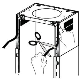
Application of Novastick Tape
Apply the Novastick tape (Ref. 16) to the front edge of the upper chimney from the top part down to the start of the lower chimney.
Island
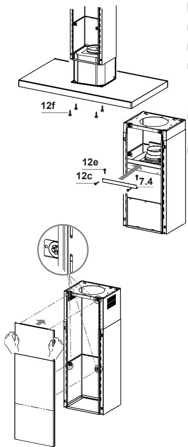
Fitting the Panel and Fixing the Hood Canopy
Before fixing the hood canopy to the frame:
Remove the grease filters from the hood canopy;
Remove any charcoal filters.
Working from below, fix the hood canopy to the frame provided, using the 4 screws (Ref. 12f) provided.
Insert the rubber supports to the upper and lower part of the panel (Ref. 3) as shown.
- Slide the lower part of the panel to the base of the chimney ensuring the metal tabs are secure.

NOTE
Make sure that the power cable has been properly inserted into the control board unit socket located on the side of the fan.
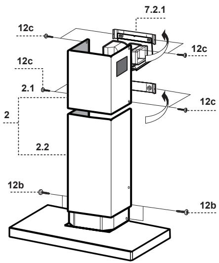
Wall Mounted
Upper Chimney Assembly
Slightly widen the two sides of the upper chimney and hook them behind the brackets (Ref. 7.2.1), making sure that they are well seated.
- Secure the sides to the brackets by using the 4 screws (Ref. 12c) supplied.
Make sure that the outlet of the extension pieces is aligned with the chimney outlets.
Lower Chimney Assembly
Slightly widen the two sides of the chimney and hook them between the upper chimney and the wall, making sure that they are well seated.
- Secure the sides of the lower chimney to the hood body by using the 2 screws (Ref. 12b) supplied.
| Manufacturer | Panasonic | ||
| Model identification | KH-AX95XBEPG | KH-TX95GBEPG | KH-TX65CBEPG |
| Type | Island | Wall | Wall |
| Power supply | 220-240 V ~ 50 Hz | ||
| Dimensions without chimney (W x D x H) | 898 x 580 x 60 mm | 898 x 460 x 60 mm | 598 x 460 x 60 mm |
| Chimney adjustable height | 730 - 1000 mm | ||
| Uncrated weight (approx.) | 25 kg | 16 kg | 13 kg |
Manufactured by: Panasonic Manufacturing U.K. Ltd.
Wyncliffe Road, Pentwyn Industrial Estate, Cardiff, S.Glam. CF23 7XB U.K.
REP. EU: Panasonic Testing Centre
Winsberging 15, 22525 Hamburg, Germany
Inhalt
Instructions d-installation. 9-25
Installation et branchement 9
Consignes de sécurité 9-11
Parties d'une hotte aspirante.....12-15
- Version flot KH-AX95XB.12-13
- Version murale KH-TX95GB/ KH-TX65CB............14-15
Dimensions 16-18
- Version flot KH-AX95XB.16
- Version murale KH-TX95GB 17
- Version murale KH-TX65GB .....18
© Panasonic Corporation 2015
E000343T0EP
FA0415-0
Printed in Italy


- Operating Instructions 2-8
- Installation Instructions. 9-25
- Installing the Appliance. 19-24
- - Island
- - Wall Mounted
- - Island and Wall Mounted
- -Island
- Specifications. 26
- Operating Instructions
- Safety Instructions
- Energy Saving Tips
- Disposal of Waste Products
- Modes of Extraction
- Control Panel
- Main Power off
- CAUTION
- NOTE
- Grease Stains
- Cleaning Metal Grease Filters
- Replacing Optional Charcoal Filter (Recirculation Mode)
- Lighting Unit
- IMPORTANT
- Wall Mounted KH-TX95GB / KH-TX65CB
- WARNING
- Wall Mounted KH-TX95GB
- Wall Mounted KH-TX65CB
- Island
- Drilling the Ceiling / Wooden Shelf
- Fixing the Frame
- Wall Mounted
- Wall Drilling and Bracket Fixing - Wall Marking:
- Mounting the Hood Body
- Island and Wall Mounted
- Ducted Mode Air Exhaust System
- Recirculation Mode Air Outlet
- Application of Novastick Tape
- Fitting the Panel and Fixing the Hood Canopy
- Upper Chimney Assembly
- Lower Chimney Assembly
- Inhalt
- Instructions d-installation. 9-25
Brand : PANASONIC
Model : KHAX95XB
Category : Range hood