CM 6 - Multimeter PCE Instruments - Free user manual and instructions
Find the device manual for free CM 6 PCE Instruments in PDF.

| Product Type | Digital Multimeter |
| Brand | PCE Instruments |
| Model | CM 6 |
| Display | LCD, 3 1/2 digit, 2000 counts |
| AC Voltage Range | 200 mV to 600 V |
| DC Voltage Range | 200 mV to 600 V |
| AC Current Range | 200 µA to 10 A |
| DC Current Range | 200 µA to 10 A |
| Resistance Range | 200 Ω to 20 MΩ |
| Continuity Test | Yes, audible buzzer |
| Diode Test | Yes |
| Transistor Test | Yes (hFE) |
| Capacitance Measurement | No |
| Frequency Measurement | No |
| Auto Ranging | No, manual ranging |
| Data Hold | Yes |
| Safety Rating | CAT II 600 V |
| Power Supply | 9 V battery (6F22) |
| Dimensions | 150 x 70 x 30 mm |
| Weight | 200 g (including battery) |
| Accessories Included | Test leads, battery, manual |
| Operating Temperature | 0°C to 40°C |
| Storage Temperature | -10°C to 50°C |
| Cleaning | Wipe with a dry cloth, do not use solvents |
| Battery Replacement | Remove screw on back, replace 9V battery |
Frequently Asked Questions - CM 6 PCE Instruments
User questions about CM 6 PCE Instruments
0 question about this device. Answer the ones you know or ask your own.
Ask a new question about this device
Download the instructions for your Multimeter in PDF format for free! Find your manual CM 6 - PCE Instruments and take your electronic device back in hand. On this page are published all the documents necessary for the use of your device. CM 6 by PCE Instruments.
USER MANUAL CM 6 PCE Instruments
This meter is a double impedance high performance true RMS digital clamp meter, which integrates multiple functions, makes your work easier, more efficient and safer.
It can measure AC/DC voltage, AC/DC current, frequency, duty, resistance, capacitance, temperature, diode, NCV, VFD, inrush current, etc.
High Input Impedance Voltage Measurement:
When measuring in a circuit, it has little effect on circuit performance. This is the desired effect for most voltage measurement applications and is especially important for sensitive electronic or control circuits.
Low Input Impedance Voltage Measurement(LoZ V):
It can safely troubleshoot sensitive electronic or control circuits and circuits that may contain false voltages, and can more reliably determine whether there is a voltage on the circuit.
SAFETY INFORMATION
Warning
Please read this manual carefully before using this product.
"WARNING" mark indicates the condition and operation which may cause danger to users.
"CAUTION" mark refers to the condition and operation which may cause damage to the instrument or equipment.
Warning
»Please read this manual carefully.
» Use the instrument strictly according to this instruction, otherwise the protection function provided by the instrument may be damaged or weakened.
» Please be careful if the measurement exceeds 30V AC true RMS, 42V AC peak or 60V DC. There may be danger of electric shock at this kind of voltage.
» Voltage applied between terminals or between each terminal and grounding point shall not exceed the rated value.
» By measuring the known voltage to check whether the meter work is normal, if it is not normal or damaged, do not use it again.
» Before using the instrument, please check whether there are cracks in the instrument shell or plastic parts damaged. If so, please do not use again.
» Before using the instrument, please check whether the probe is cracked or damaged. If so, please replace the same type and the same electrical specifications.
» Do not exceed the lowest rated Category of Measurement (CAT) rating in products, probes or accessories.
» Do not measure the current when the probe is inserted into the input jack.
»Don't work alone.
»Please comply with local and national safety code.
» Wear personal protection equipment (such as approved rubber gloves, masks and flame retardant clothes, etc.) to prevent being damaged by electric shock and electric arc due to exposed hazardous live conductor.
» When it shows low battery indicator, please replace the battery in time in case of any measurement error.
» Do not use the instrument around explosive gas, steam or in wet environment.
» When using the probe, please put your fingers behind the finger protector of the probe.
» When measuring, please connect the neutral wire or the ground wire firstly, then connect the live wire; When disconnecting, please disconnect the live wire firstly, then disconnect the neutral wire and ground wire.
» Before opening the outer cabinet or battery cover, please remove the probe on the instrument. Do not use the instrument in the circumstances that the instrument is taken apart or battery cover is opened.
» It only meets the safety standards when the instrument is used together with the supplied probe. If the probe is damaged and needs to replace, the probe with same model number and same electrical specifications must be used for replacement.
SAFETY SYMBOLS
| [1972] | High voltage warning |
 | AC |
 | DC |
 | AC or DC |
 | Warning, danger |
 | Ground |
 | Double insulation/reinforced insulation protection |
 | Low battery |
 | Product complies with all relevant European laws |
 | Frequency converter |
 | Inrush current measurement |
 | Low Input Impedance Voltage Measurement |
 | The additional product label shows that do not discard this electrical/electronic product into household garbage. |
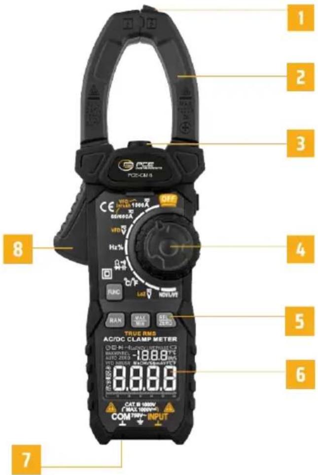
PANEL DESCRIPTION
- N CV senser
- Clamp
- Flashlight
- Knob switch
- Function key
- Display
- Measuring input jack
- Trigger
text_image
1 2 3 4 5 6 7 8 9 OFF VDD INT/SS 1000A 60/600A VDD Hz% RUNC LAD NOVA/VE RAN MAX MAX SELECT ZERO TRUE RMS AC/DC CLAMP METER H-ISO/INT/SS 1000A MAX/INT/SS 1000A AUTO ZERO HDD MIN/SS 1000A HDD MIN/SS 1000A CAT: H 1000V (MAX 1000V) COM: 750V~ INPUTFUNCTION OPERATION

Function selection key
When there are multiple functions in one position, press this key to switch.

Range selection key
When the meter is turned on, the meter defaults to the AUTO range mode and displays the "auto" character.
It is effective in 60/600A, ACV, DCV and resistor functions. Press this key to enter the manual range mode, continue to press to enter the higher range until the highest range, and press again to return to the lowest range. In manual range mode, press this key for more than 2 seconds to return to automatic range.

Max/Min View Key
At current, voltage, resistance and temperature functions. Press this key to cycle through the maximum and minimum values; Press this key for more than 2 seconds to exit this mode. After entering this mode, the meter will automatically switch to manual range. When entering the maximum/minimum viewing mode, first press the range key to switch to the most suitable range.

Relative Value Key
In the current, voltage, resistance, capacitance and temperature, this key is the relative value key. Press this key to turn on relative value measurement, the display screen will display „REL“, and press it again to exit the relative value measurement function.

Data Hold/Flashlight Key
Press this key to turn on data hold, and the display screen displays „H“ character to show data locking. Press again to cancel; Press this key for more than 2 seconds to turn on or off the flashlight.
OPERATIONS
Auto power off
» No operation in 15 minutes. The meter will power off automatically to save battery energy. After automatic power off, press any key to power on.
» If you press the „FUNC“ key and keep, Then turn on the meter power, the auto power off function will be cancelled.
Inrush current measurement
» Turn the knob to à ,and select Proper range(60/600A or 1000A), Press „FUNC“ key until the “inrush” character is displayed
» Then press the trigger to open the clamp, clamp the conductor to be tested, and then slowly release the trigger until the clamp are completely closed, and determine whether the conductor to be tested is clamped in the center of the pliers, if the conductor is not in the center of the pliers, additional errors will occur.
» Turn on the equipment to be tested (such as motor) and then trigger the meter by inrush current.
»Read the measurement results on the display.
WARNING
» Before use, use the meter to test the known voltage or current, and confirm that the meter is in good condition.
» Pay special attention to safety when measuring high voltage to avoid electric shock or personal injury.
NOTE
» Please place the measured conductor in the center of the clamp head, otherwise additional error will occur.
»The measuring time of inrush current is about 100ms.
VFD current measurement
» Turn the knob to Ã, and select Proper range (60/600A or 1000A), Press „FUNC“ key until the „VFD“ character is displayed.
» Then press the trigger to open the clamp, clamp the conductor to be tested, and then slowly release the trigger until the clamp are completely closed, and determine whether the conductor to be tested is clamped in the center of the pliers, if the conductor is not in the center of the pliers, additional errors will occur.
»Read the measurement results on the display
WARNING
» Before use, use the meter to test the known voltage or current, and confirm that the meter is in good condition.
» Pay special attention to safety when measuring high voltage to avoid electric shock or personal injury.
» Please do not use VFD function to verify the presence of dangerous voltage or current, which may exceed the indicated value to avoid electric shock or personal injury.
NOTE
» Please place the measured conductor in the center of the clamp head, otherwise additional error will occur
AC current measurement
» Turn the knob to , and select proper range (60/600A or 1000A), AC character is displayed.
» Then press the trigger to open the clamp, clamp the conductor to be tested, and then slowly release the trigger until the clamp are completely closed, and determine whether the conductor to be tested is clamped in the center of the pliers, if the conductor is not in the center of the pliers, additional errors will occur.
»Read the measurement results on the display
WARNING
» Before use, use the meter to test the known voltage or current, and confirm that the meter is in good condition.
» Pay special attention to safety when measuring high voltage to avoid electric shock or personal injury.
» Please do not use VFD function to verify the presence of dangerous voltage or current, which may exceed the indicated value to avoid electric shock or personal injury.
NOTE
» Please place the measured conductor in the center of the clamp head, otherwise additional error will occur.
VFD Voltage measurement
» Turn the knob to V or LoZ V, Press „FUNC“ key until the „VFD“ character is displayed.
» Insert red probe to "INPUT" jack, insert black probe to "COM" jack.
» Connect the probe with voltage source or both ends of load in parallel for measurement.
»Read the measurement results on the display.
WARNING
» Before use, use the meter to test the known voltage or current, and confirm that the meter is in good condition.
» Pay special attention to safety when measuring high voltage to avoid electric shock or personal injury.
» Please do not use VFD function to verify the presence of dangerous voltage or current, which may exceed the indicated value to avoid electric shock or personal injury.
CAUTION
» When using LoZ V (low input impedance) measurement, the continuous measurement time cannot exceed 1 minute.
» Do not use LoZ mode to measure voltage in circuits that may be damaged by the low impedance of this mode.
AC/DC Voltage measurement
» Turn the knob to V or LoZ V,Press key „FUNC“ until the AC or DC character is displayed.
» Insert red probe to "INPUT" jack, insert black probe to "COM" jack.
» Connect the probe with voltage source or both ends of load in parallel for measurement.
»Read the measurement results on the display.
WARNING
» Before use, use the meter to test the known voltage or current, and confirm that the meter is in good condition.
» Pay special attention to safety when measuring high voltage to avoid electric shock or personal injury.
» Please do not use VFD function to verify the presence of dangerous voltage or current, which may exceed the indicated value to avoid electric shock or personal injury.
CAUTION
» When using (low input impedance) measurement, the continuous measurement time cannot exceed 1 minute.
» Do not use LoZ mode to measure voltage in circuits that may be damaged by the low impedance of this mode.
NOTE
»High input impedance: approx. 10MΩ.
Low input impedance: approx. 300kΩ.
Frequency/duty measurement
»Turn the knob to Hz%
» Insert red probe to "INPUT" jack, insert black probe to "COM" jack.
» Connect the probe with voltage source or both ends of load in parallel for measurement.
»Read the measurement results on the display.
WARNING
» Before use, use the meter to test the known voltage or current, and confirm that the meter is in good condition.
» Pay special attention to safety when measuring high voltage to avoid electric shock or personal injury.
Resistance measurement
»Turn the knob to
» Insert red probe to "INPUT" jack, insert black probe to "COM" jack.
» Connect the probe to the both ends of resistor or circuit to be tested for measurement.
»Read the measurement results on the display.
WARNING
» When measuring circuit impedance, determine that the power supply is disconnected and the capacitor in the circuit is completely discharged.
Continuity test
» Turn the knob to ⬤️, Press key „FUNC“ until the Symbol ➕ is displayed.
» Insert red probe to "INPUT" jack, insert black probe to "COM" jack.
» Connect the probe to the both ends of resistor or circuit to be tested for measurement.
» If the resistance value of the tested resistor or circuit is less than about 30Ω, and the LED indicator light is on at the same time, The resistance value will be displayed.
WARNING
» When measuring circuit continuity, determine that the power supply is disconnected and the capacitor in the circuit is completely discharged.
Diode test
» Turn the knob to 📂, Press key „FUNC“ until the Symbol ➤ is displayed.
» Insert red probe to "INPUT" jack, insert black probe to "COM" jack.
» Connect the red probe to diode anode and connect the black probe to diode cathode.
»Read the measurement results on the display.
WARNING
» When measuring diode, determine that the power supply is disconnected and the capacitor in the circuit is completely discharged.
Capacitance measurement
» Turn the knob to ^-1 , Press key „FUNC“ until capacitance function.
» Insert red probe to "INPUT" jack, insert black probe to "COM" jack.
» Connect the probe to the both ends of capacitance to be tested for measurement.
»Read the measurement results on the display.
WARNING
» When measuring capacitance, determine that the power supply is disconnected and the capacitor in the circuit is completely discharged.
Temperature measurement
»Turn the knob to °C / °F
» Insert the K-type thermocouple, the positive pole (red) of the thermocouple into the "INPUT" jack, and the negative pole (black) into the "COM" input.
»Contact the thermocouple probe with the measured object.
»Read the measurement results on the display.
WARNING
» When measuring temperature with thermocouple, the probe of thermocouple can't touch the charged object, otherwise it may damage the instrument and may suffer electric shock or personal injury.
NOTE
» It takes a long time for the cold end of thermocouple to be restored in the meter to achieve thermal balance with the environment.
Non-contact AC Voltage (NCV) Detection
»Turn the knob to NCV/LIVE, the "NCV" symbol is displayed
»Then NCV sensor gradually approaches the detected point.
» When a weak electromagnetic field signal is sensed, the „---L“ character is displayed, the buzzer emits a slow beep sound, and the green LED indicator light is on.
» When a strong electromagnetic field signal is sensed, the „---H“ character is displayed, the buzzer emits a quick beep sound, and the red LED indicator light is on
NOTE
» When using NCV function, please remove the probe, otherwise the detection Sensitivity will be affected.
Live Detection
» Turn the knob to NCV/LIVE, Press key „FUNC“ until the “LIVE” Symbol is displayed.
»Insert red probe to "INPUT" jack.
» Connect the red probe to the conductor to be tested for measurement.
» When a low voltage is detected, the „---L“ character is displayed, the buzzer emits a slow beep sound, and the green LED indicator light is on.
» When a high voltage is detected, the „---H“ character is displayed, the buzzer gives a quick beep sound, and the red LED indicator light is on.
»In general, the fire line detected at this time
NOTE
» When using Live function, please remove the black probe, otherwise the detection Sensitivity will be affected.
GENERAL TECHNICAL SPECIFICATIONS
»Environment condition of using:
Safety: IEC 61010-1, Pollution level 2
IEC 61010-2-032: CAT III 1000V / CAT IV 600V
IEC 61010-2-033: CAT III 1000V / CAT IV 600V
Altitude < 2000m.
Working environment temperature and humidity:
0 ... 40°C (<80% RH, <10°C non condensing);
Storage environment temperature and humidity:
-10 ... 60°C (<70% RH, remove the battery);
» Temperature coefficient: 0.1 accuracy/°C (<18°C or >28°C);
» MAX. Voltage between terminals and earth ground: AC750V or DC1000V;
» Display: 6000 counter readout. Automatically display the unit symbols according to the shift of the measurement function;
»Over range indication: displays "OL";
» Low battery indication: when the battery voltage is lower than the normal working voltage, “☐” will be displayed;
»Input polarity indication: automatically display “-”.
»Clamp opening size: 40mm;
»Auto power off: approx. 15 minutes;
»Power: 2 x 1.5V AAA alkaline batteries.
ACCURACY SPECIFICATIONS
The accuracy applies within one year after the calibration.
Reference condition: the environment temperature 18^ C to 28^ C, the relative humidity is no more than 80% accuracy: ±(% reading + word).
AC current
| Range Resolution Accuracy | ||
| 60A 0.01A ±(2.5%reading+8) | ||
| 600A 0.1A VFD: ±(5.0%reading+10) | ||
| 1000A 1A INRUSH: ±(5.0%reading-10) |
MAX current: 1000A; True RMS
Frequency range: 0.1 ... 600A; 40Hz ... 400Hz; 600 ... 1000A; 40Hz ... 60Hz.
DC voltage
| Range Resolution Accuracy | ||
| 600mV 0.1mV | ±(0.5%reading+5) | |
| 6V 0.001V | ||
| 60V 0.01V | ||
| 600v 0.1V | ||
| 1000V 1V ±(0.8%reading+5) |
Input impedance: 10MΩ (LoZ:300kΩ)
Overload protection: AC750V / DC1000V
Maximum input voltage: AC750V / DC1000V
Note: In the small voltage range, when the probe is not connected to the measuring circuit, the meter display reading may not be zero, which is normal and will not affect the normal measurement.
AC voltage
| Range Resolution Accuracy | ||
| 600mV 0.1mV | ±(0.8%reading+5) | |
| 6V 0.001V | ||
| 60V 0.01V | ||
| 600v 0.1V | ||
| 750V 1V ±(1.0%reading+5) | ||
| VDF(750V) 0.1V ±(2.0%reading+5) |
Input impedance: 10MΩ (LoZ:300kΩ)
Overload protection: AC750V / DC1000V
Maximum input voltage: AC750V / DC1000V
Frequency range: 40Hz ... 1kHz; True RMS
Note: In the small voltage range, when the probe is not connected to the measuring circuit, the meter display reading may not be zero, which is normal and will not affect the normal measurement.
Resistance
| Range Resolution Accuracy | ||
| 600Ω 1Ω | ±(1.0%reading+5) | |
| 6KΩ 0.001 KΩ | ||
| 60KΩ 0.01 KΩ | ||
| 600KΩ 0.1KΩ | ||
| 6MΩ 0.001 MΩ | ||
| 60MΩ 0.01 MΩ |
Overload protection: 250V
Diode/Continuity
 | Test Voltage Approx. 1VOverload protection: 250V | |
 | It displays the approximate forward voltage value of the diode | Forward DC current is about 1.5mAOverload protection: 250V |
Capacitance
| Range Resolution Accuracy | ||
| 10nF 0.001nF | ±(4.0%reading+5) | |
| 100nF 0.01nF | ||
| 1000nF 0.1nF | ||
| 10μF 0.001μF | ||
| 100μF 0.01μF | ||
| 1000μF 0.1μF | ||
| 10mF 0.001mF | ||
| 100mF 0.01mF ±(5.0%reading+10) |
Overload protection: 250V
Frequency/duty
| Range Resolution Accuracy | ||
| 10Hz 0.001Hz | ±(1.0%reading+3) | |
| 100Hz 0.01Hz | ||
| 1000Hz 0.1Hz | ||
| 10KHz 0.001KHz | ||
| 100kHz 0.01kHz | ||
| 1000kHz 0.1kHz | ||
| 10MHz 0.001MHz ±(3.0%reading+3) | ||
| 1~99% 0.1% |
Overload protection: 250V;
Hz/Duty:
Range: 0 ... 10MHz
Voltage sensitivity: 0.5 ... 10V AC
(As the frequency increases, the voltage should increase accordingly.)
Through mode V:
Range: 10Hz ... 10 kHz
Voltage sensitivity: >0.5V AC
(As the frequency increases, the voltage should increase accordingly).
Clamp measuring frequency:
Range: 10Hz ... 1 kHz
Current sensitivity: >20A
(As the frequency increases, the current should increase accordingly).
Temperature
| Unit Accuracy | ||
| °C -20 °C ... 0 °C ±3 °C | ||
| 0 °C ... 400 °C ±1.0% or ±2 °C | ||
| 400 °C ... 1000 °C ±2.0% | ||
| °F -4 °F ... 32 °F | ±6 °F | |
| 32 °F ... 752 °F | ±1.0% or ±4 °F | |
| 752 °F ... 1832 °F | ±2.0% | |
Note: The above precision does not include the error of thermocouple probe.
MAINTENANCE
To avoid electric shock, remove the probe before opening the battery cover or back cover. General maintenance.
» Maintenance and service of this instrument must be carried out by professional qualified maintenance personnel or maintenance department.
» Use wet cloth or mild detergent regularly to clean the shell. Do not use abrasives or solvents. Wipe the contacts in the socket with a clean cotton swab soaked in alcohol.
BATTERY INSTALLATION OR REPLACEMENT
The meter uses three AAA 1.5V alkaline batteries.
Please install or replace the batteries according to the following steps.
»Turn off the power of the meter and remove theprobe.
» Use screwdriver to unscrew the screw that fixes the battery cover and remove the battery cover.
» Remove the old battery and install the new battery according to the polarity of the battery marked in the battery box.
» After installing the new battery, cover the battery cover and lock the screw.
» To avoid the possibility of electric shock or personal injury caused by incorrect reading, replace the battery immediately when the BATTERY sign is displayed on the display screen.
» Please use the same type of batteries, do not use substandard batteries.
» In order to ensure safe operation and maintenance of the instrument, please take out the battery when not in use for a long time, in order to prevent damage to the product caused by battery leakage.
DISPOSAL
For the disposal of batteries in the EU, the 2006/66/EC directive of the European Parliament applies. Due to the contained pollutants, batteries must not be disposed of as household waste. They must be given to collection points designed for that purpose. In order to comply with the EU directive 2012/19/EU we take our devices back. We either re-use them or give them to a recycling company which disposes of the devices in line with law. For countries outside the EU, batteries and devices should be disposed of in accordance with your local waste regulations. If you have any questions, please contact PCE Instruments.
PCE INSTRUMENTS CONTACT INFORMATION
Germany France Spain
PCE Deutschland GmbH PCE Instruments France EURL PCE Ibérica S.L.
Im Langel 26 23, rue de Strasbourg Calle Mula, 8
D-59872 Meschede 67250 Soultz-Sous-Forets 02500 Tobarra (Albacete)
Chester Rd, Old Trafford
Manchester M32 ORS Capannori (Lucca)
United Kingdom
Tel: +44 (0) 161 464902 0
Fax: +44 (0) 161 464902 9
info@pce-instruments.co.uk
www.pce-instruments.com/english
Italy
PCE Italia s.r.l.
Via Pesciatina 878 / B-Interno 6
55010 Loc. Gragnano
Pehlivan Sok. No.6/C
Türkiye
Tel: 0212 471 11 47
www.pce-instruments.com/turkish
The Netherlands
PCE Brookhuis B.V.
Twentepoort West 17
7609 RD Almelo
Nederland
Telefoon: +31 (0)53 737 01 92
info@pcebenelux.nl
www.pce-instruments.com/dutch
United States of America
PCE Americas Inc.
1201 Jupiter Park Drive, Suite 8
Jupiter / Palm Beach
33458 FL
USA
Tel: +1 (561) 320-9162
Fax: +1 (561) 320-9176
info@pce-americas.com
www.pce-instruments.com/us
Denmark
PCE Instruments Denmark ApS
Birk Centerpark 40
7400 Herning
Denmark