DFG N 50K - Multimeter PCE Instruments - Free user manual and instructions
Find the device manual for free DFG N 50K PCE Instruments in PDF.


| Product Type | Digital Multimeter |
| Brand | PCE Instruments |
| Model | DFG N 50K |
| Measurement Functions | AC/DC Voltage, AC/DC Current, Resistance, Continuity, Diode Test, Capacitance |
| Display | LCD, 6000 counts |
| Auto-Ranging | Yes |
| Data Hold | Yes |
| Backlight | Yes |
| Safety Rating | CAT II 600V |
| Power Supply | 9V battery (6F22) |
| Dimensions (H x W x D) | 180 x 80 x 35 mm |
| Weight | Approx. 300 g |
| Accessories Included | Test leads, 9V battery, user manual |
| Warranty | 2 years |
| Operating Temperature | 0°C to 40°C |
| Storage Temperature | -10°C to 60°C |
| Humidity | <80% RH |
| Cleaning Instructions | Wipe with a damp cloth, do not use solvents |
| Safety Precautions | Do not exceed rated voltage/current; use appropriate test leads |
| Repairability | Contact PCE Instruments for spare parts and service |
Frequently Asked Questions - DFG N 50K PCE Instruments
User questions about DFG N 50K PCE Instruments
0 question about this device. Answer the ones you know or ask your own.
Ask a new question about this device
Download the instructions for your Multimeter in PDF format for free! Find your manual DFG N 50K - PCE Instruments and take your electronic device back in hand. On this page are published all the documents necessary for the use of your device. DFG N 50K by PCE Instruments.
USER MANUAL DFG N 50K PCE Instruments




Bedienungsanleitung
User Manual
PCE-DFG N Series Digitales Kraftmessgerät | Digital Force Gauge
User manuals in various languages (français, taliano, español, português, nederlands, türk, polski, русский, 中文) can be downloaded here:
www.pce-instruments.com
| L [mm] | H [mm] | W1[mm] | H1 [mm] | M [mm] | Gewicht | |
| 1 kN | 50,8 | 76,2 | 20,8 | 15,3 | M10 x 1,5 | 540 g |
| 2,5 ... 5 kN | 50,8 | 76,2 | 20,8 | 13,6 | M12 x 1,75 | 540 g |
| 10 kN | 50,8 | 76,2 | 27,2 | 12,1 | M12 x 1,75 | 680 g |
| 20 ... 50 kN | 76,2 | 101,6 | 27,2 | 20 | M20 x 1,5 | 1350 g |
| 100 kN | 112,78 | 177,8 | 42,93 | - | M30 x 2 | 6800 g |
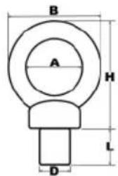
| A [mm] | B [mm] | H [mm] | L [mm] | D [mm] | Max Last | Gewicht | |
| 1 kN | 24 | 45 | 45 | 20 | M10 | 0,25 t | 110 g |
| 2,5 kN | 29 | 53 | 53 | 22 | M12 | 0,4 t | 175 g |
| 5 kN | 35 | 62 | 63 | 22 | M12 | 0,7 t | 260 g |
| 10 kN | 39 | 71 | 73 | 22 | M12 | 1 t | 395 g |
| 20 kN ... 50kN | 40 | 72 | 71 | 30 | M20 | 6 t | 450 g |
| 100 kN | 60 | 108 | 109 | 45 | M30 | 12 t | 1700 g |
8 Kontakt
Please read this manual carefully and completely before you use the device for the first time. The device may only be used by qualified personnel and repaired by PCE Instruments personnel. Damage or injuries caused by non-observance of the manual are excluded from our liability and not covered by our warranty.
- The device must only be used as described in this instruction manual. If used otherwise, this can cause dangerous situations for the user and damage to the meter.
- The instrument may only be used if the environmental conditions (temperature, relative humidity, ...) are within the ranges stated in the technical specifications. Do not expose the device to extreme temperatures, direct sunlight, extreme humidity or moisture.
- The case should only be opened by qualified PCE Instruments personnel.
- Never use the instrument when your hands are wet.
- You must not make any technical changes to the device.
- The appliance should only be cleaned with a damp cloth. Use only pH-neutral cleaner, no abrasives or solvents.
- The device must only be used with accessories from PCE Instruments or equivalent.
- Before each use, inspect the case for visible damage. If any damage is visible, do not use the device.
- Do not use the instrument in explosive atmospheres.
- ATTENTION: For impact tests, the maximum measurable value of the force gauge should be twice as high as the applied impact load.
- When doing impact tests, wear a mask and protective gloves to avoid injuries.
- Do not use the test stand when it is bent or damaged. Dropping can cause injuries.
- This device only measures tensile and compressive forces. The test head must not be bent or twisted.
- Overloading, excessive impact loads or applied forces other than tensile and compressive forces can cause damage to the sensor.
- Do not press the keys with pointed objects.
- Keep the force gauge away from water, oil and other liquids.
- Store the meter in a cool, dry place without any occurrence of vibration.
- Wire the ports as described in this manual. Non-observance of the instructions can cause circuit failure or problems with your computer.
- Make sure that the mains adaptor is securely connected to the power outlet as otherwise short circuits and thus electric shocks and fire can occur.
- When the battery is fully charged, remove the mains adaptor immediately to avoid overheating, fire or accidents.
- Non-observance of the safety notes can cause damage to the device and injuries to the user.
We do not assume liability for printing errors or any other mistakes in this manual.
We expressly point to our general guarantee terms which can be found in our general terms of business.
Safety symbols
Safety-related instructions the non-observance of which can cause damage to the device or personal injury carry a safety symbol.
| Symbol | Designation / description | |
 | General warning signNon-observance can cause damage to the device and injuries to the user. | |
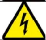 | Warning: electrical voltageNon-observance can cause electric shock. | |
2 Specifications
2.1 Technical specifications
Force gauge with internal dynamometric cell
| Specification | Value / version | ||||
| Model | PCE-DFG N5 | PCE-DFG N10 | PCE-DFG N20 | PCE-DFG N200 | PCE-DFG N500 |
| Range | 0 ... 5 N | 0 ... 10 N | 0 ... 20 N | 0...200 N | 0...500 N |
| Resolution | 0.001 N | 0.005 N | 0.01 N | 0.1 N | 0.1 N |
| Accuracy | |||||
| Dimensions | 200 x 97 x 42 mm | ||||
| Weight | approx. 540g | ||||
Force gauge with external dynamometric cell
| Specification | Value / version | |||
| Model | PCE-DFG N 1K | PCE-DFG N 2,5K | PCE-DFG N 5K | PCE-DFG N 10K |
| Range | 1,000 N / 100 kg | 2,500 N / 250 kg | 5,000 N / 500 kg | 10,000 N / 1 t |
| Resolution | 0.5 N | 1 N | 1 N | 5 N |
| Accuracy | 0,1 % F.S. | |||
| Units | N, kg, lb, KPa | |||
| Model | PCE-DFG N 20K | PCE-DFG N 50K | PCE-DFG N 100K | |
| Range | 20,000 N / 2t | 50,000 N / 5 t | 100,000 N / 10 t | |
| Resolution | 0.002 kN / 2 N | 0.005 kN / 5 N | 0.01 kN / 10 N | |
| Accuracy | 0,2 % F.S. | |||
| Units | kN, t, klb, MPa | |||
Further versions on request
General specifications
| Specification | Value |
| Cell protection class | IP 67 |
| Device dimensions | 162 x 82 x 41 mm |
| Device weight | 325 g |
| Display | 2.8" TFT graphical display |
| Alarm modes | within, beyond, fracture, off |
| Sampling rate | 6 ... 1600 Hz device6...800 Hz software |
| Memory | 100 measurements |
| Power supply | Ni-Hi rechargeable battery6 V, 1600 mAhBattery life10 hours |
| Mains adaptor | 12 VDC 1 A; |
| Outputs | Communication via USBOutput port 12 V, 50 mA |
| Operating conditions | -10 ... +50 °C; 5 ... 95 % RH, non-condensing |
| Protection class | IP 54 |
2.2 Delivery contents
Version with internal cell:
1 x force gauge PCE-DFG N
5 x test head adaptors (pointed head adaptor, notched head adaptor, chisel head adaptor, flat head adaptor, hook adaptor)
1 x extension rod incl. adaptor
1 x USB cable
1 x mains adaptor
1 x software
1 x user manual
Version with external cell:
1 x force gauge PCE-DFG N
1 x dynamometric cell
2 x eyebolt (only up to 10 kN load cell)
1 x case for the meter
1 x case for the dynamometric cell
1 x USB cable
1 x mains adaptor
1 x software
1 x user manual
2.3 Optional accessories
PCE-C-S-1000N-C3 load cell 1,000 N / 100 kg / M10
PCE-C-S-2500N-C3 load cell 2,500 N / 250 kg / M12
PCE-C-S-5000N-C3 load cell 5,000 N / 500 kg / M12
PCE-C-S-10000N-C3 load cell 10,000 N / 1 t / M12
PCE-C-S-20KN-C3 load cell 20.000 N / 2 t / M20
PCE-C-S-50KN-C3 load cell 50.000 N / 5 t / M20
PCE-C-S-100KN-C3 load cell 100.000 N / 10 t / M30
PCE-C-A-1000N-EB eyebolt M10 1,000 N (set: 2 pieces)
PCE-C-A-2500N-EB eyebolt M12 2,500 N (set: 2 pieces)
PCE-C-A-5000N-EB eyebolt M12 5,000 N (set: 2 pieces)
PCE-C-A-10000N-EB eyebolt M12 10,000 N (set: 2 pieces)
PCE-C-A-60KN-EB eyebolt M20 / 60.000 N / 6 t (set: 2 pieces)
PCE-C-A-120KN-EB eyebolt M30 / 120.000 N / 12 t (set: 2 pieces)
PCE-C-A-1000N-RE eyebolt with joint head M10 1,000 N (set: 2 pieces)
PCE-C-A-10000N-RE eyebolt with joint head M12 10,000 N (set: 2 pieces)
PCE-C-A-1000N-HB clip bolt M10 1,000 N (set: 2 pieces)
PCE-C-A-2500N-HB clip bolt M12 2,500 N (set: 2 pieces)
PCE-C-A-5000N-HB clip bolt M12 5,000 N (set: 2 pieces)
PCE-C-A-10000N-HB clip bolt M12 10,000 N (set: 2 pieces)
CAL-PCE-DFG N calibration certificate
Further accessories on request

3 System description
3.1 Device
Version with internal dynamometric cell
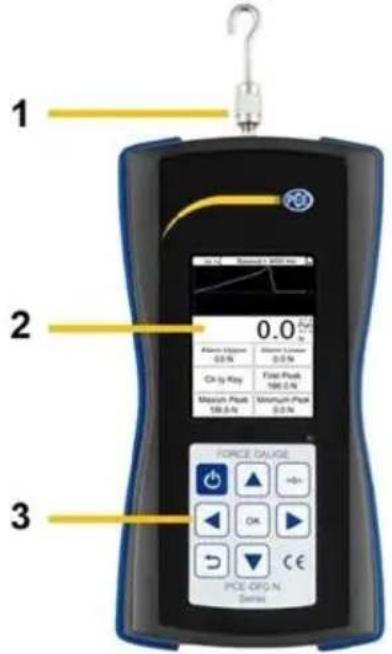
1 Measuring shaft
2 Display
3 Keypad
4 Extension rod
5 Chisel head adaptor
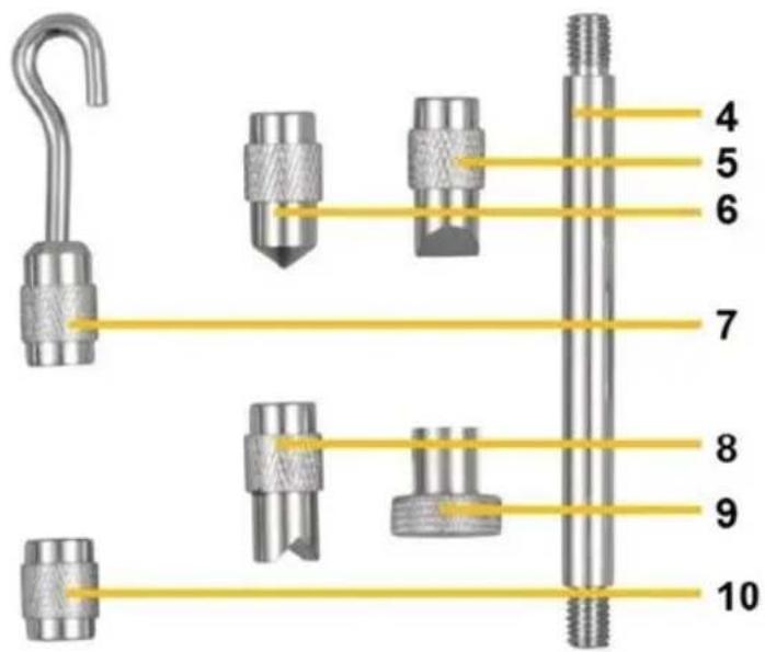
6 Pointed head adaptor
7 Hook adaptor
8 Notched head adaptor
9 Flat head adaptor
10 Adaptor for extension rod
3.2 Interfaces
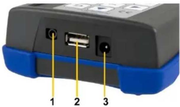
1 Input / output interface
2 USB interface
3 Power connection
Circuit diagram of output port
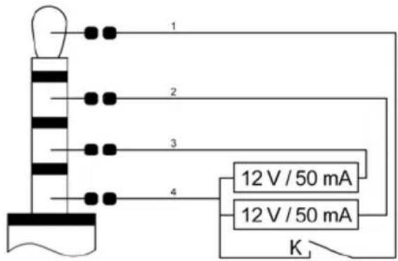
1 Switch of external input / output
2 Output lower limit
3 Output upper limit
4 GND
3.3 Display
In measurement mode
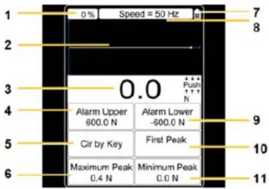
1 memory usage
2 measurement curve
3 force value
4 upper alarm value
5 clear by key
6 maximum peak
7 battery level indicator
8 set sampling rate
9 lower alarm value
10 first peak
11 minimum peak
3.4 Function keys
| Key | Designation | Function | |||||
| Single measurement mode | Capture mode | Online measurement mode | Memory and query mode | Menu mode | |||
 | On / Off | Switch off | - | Switch off | - | - | |
 | Back | - | Close capture mode | - | Exit | Exit / close parameter settings | |
 | Zero | Zero setting | - | Zero setting | - | - | |
 | Up | - | - | - | Up | Up | |
 | Down | Activate memory and query mode | - | - | Switch to upper window | Down | |
 | OK | Open parameter settings | Stop capturing | - | Show report and reading | Confirm parameter setting | |
 | Left | Start curve capturing | - | Start curve capturing | Move flashing number left by one digit | ||
 | Right | Delete peak value | - | Delete peak value | Move flashing number right by one digit | ||
4 Getting started
4.1 Power supply
The PCE-DFG N is equipped with a rechargeable 1600 mAh 6 V Ni-Hi battery that should only be charged by means of the mains adaptor which is included in the standard delivery.
Charging can take 8 to 10 hours and should only be started when the battery is completely flat. Excessively frequent or long-time charging shortens the battery life.
When the battery is fully charged, it will last up to 10 hours of continuous use. The device can also be used during charging. The battery can be charged approx. 500 times.
4.2 Settings
When you are in measurement mode, press the OK key to enter the settings screen which is divided into 2 pages:
Page 1 Page 2
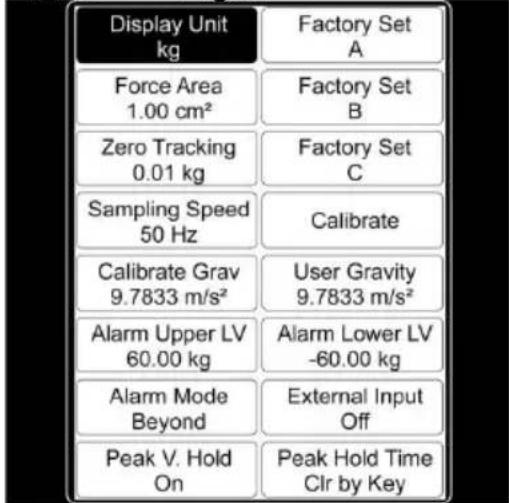
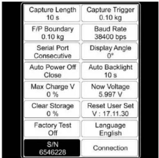
In order to change settings, select the menu item with the arrow keys and confirm with the OK key. The values can then be changed by means of the arrow keys. Then press "OK" to confirm the settings or the Back key to discard.
| Function | Description page 1 |
| Display Unit | The display unit can be set to: „N“, „kg“, „lb“ or „KPa“ |
| Force Area | The force area can be set to a value between 999.99cm^2 and 0.01cm^2 and is included in the calculation if the display unit selected is „kPA“(important for the accuracy). |
| Zero Tracking | For zero tracking, you can set:„Off“, „0.1 N“, „0.2 N“, „0.3 N“, „0.4 N“, „0.5 N“Values below the value set are automatically excluded before the zero point stabilises. After stabilisation of the reading, the sampling rate will be 1 x per second. Deviations from the measured value which are below the set value are automatically excluded in order to keep the displayed values. |
| Sampling Speed | You can set how many measurements are taken per second. A value between 6 and 1600 Hz can be set here.Note: The higher the sampling rate, the lower the accuracy will be.Higher sampling rates are suitable for dynamic measurements whereas lower sampling rates are more suitable for static and slow measurements. |
| Calibrate Grav | Enter the gravity at the place of calibration. |
| Alarm Upper | The upper alarm can be set to +/- 9999.9. |
| Alarm Mode | You can choose “Within” (within alarm limit), “Beyond” (outside alarm limit), “Fracture” (overload alarm) or “Off”. |
| If you select “Within” or “Beyond”, the display will show information on the alarm.If you select “Fracture”, Alarm Upper LV and Alarm Lower LV will automatically be set to “Fracture Alarm” and „Fracture Stop of Peak“. Set these two parameters. When the force reaches the fracture alarm value or when the sample breaks, the display will show some information on the alarm. | |
| Peak V. Hold | You can select „On“ or “Off”. If “Off” is selected, the peak value will not be indicated in the display. |
| Factory Set A | Only relevant for customer service. |
| Factory Set B | Only relevant for customer service. |
| Factory Set C | Only relevant for customer service. |
| Calibrate | Press OK to start the calibration. The calibration result will have a considerable influence on the accuracy of measurement. There are two possibilities to calibrate the meter:1. Entering saved data:The user enters the saved calibration data. The calibration is done without any other devices or weights.2. Standard calibration:The force gauge is calibrated by means of the calibration stand or calibration weight. |
| User Gravity | Here, you can set the gravity at the place of use. The value can be between 9.700 and 9.900 N/kg. This parameter is used for the gravity correction. The following formula must be used for this:Displayed value = reading + reading x (gravitation place of calibration – gravitation place of use) |
| Alarm Lower | The lower alarm can be set to +/- 9999.9. |
| External Input | You can select “On” or “Off”. If “On” is selected, the external switch can be switched on and the force gauge enters curve capture mode.Note: The capturing duration depends on the sampling rate.Capturing duration in seconds = number of recorded data / sampling rate |
| Peak Hold Time | You can select “Clr by Key” or certain periods between 1 and 60 seconds. If “Clr by Key” is selected, the peak value will not be changed until the “Arrow Right key or the “Zero Set” button is applied. If a period between 1 and 60 seconds is selected, the peak value will automatically be measured again after the set time has passed. The peak value can also be re-measured by applying the “Arrow Right key or the “Zero Set” button. |
| Function | Description page 2 |
| Capture Length | You can set a value between 1 and 1280 seconds. This value represents the duration of curve capturing in capture mode which depends on the sampling rate:Sampling rate 6 Hz: 1 ~ 1280 secondsSampling rate 12 Hz: 1 ~ 640 secondsSampling rate 25 Hz: 1 ~ 320 secondsSampling rate 50 Hz: 1 ~ 160 secondsSampling rate 100 Hz: 1 ~ 80 secondsSampling rate 200 Hz: 1 ~ 40 secondsSampling rate 400 Hz: 1 ~ 20 secondsSampling rate 800 Hz: 1 ~ 10 secondsSampling rate 1600 Hz: 1 ~ 5 seconds |
| F/P Boundary | You can set a value between 1 and 99999. This setting is used during peak value measurement to determine the first peak value. When you press the Arrow Right key, a new peak value measurement will start. Meanwhile, the values peak-to-peak (Vmax), valley-to-peak (Vmin) and new peak (Vnew) are updated continuously. For example, if 10 is set as the criterion, Vmax or Vmin will be counted as the first peak value when the absolute value of (Vmax - Vnew) or (Vmin - Vnew) is above 10. |
| Serial Port | This port is used to control the real-time data transfer. The following parameters can be set:Prohibit: The real-time data transfer of the serial interface is prohibited.Key/Order: A single output will take place when you press the Up key or when an output command is received. When the force gauge is connected to a computer, the programmes on the computer will automatically disable the output function.Change: A single output will take place when the measuring data change.Stabilize: A single output will take place when the reading stabilises.Consecutive: The measuring data are transferred without interruption. |
| Auto Power Off | This function reduces the energy consumption. The force gauge will automatically power off when it has not been used for a certain period of time. |
| Max Charge V | This window shows the maximum voltage of the battery. |
| Clear Storage | Here, you can delete saved measurement reports and curves.Important information:When the memory is full, all data will automatically be deleted to enable new data to be saved. |
| Factory Test | Only relevant for customer service. |
| S/N | This window shows the serial number of the device which cannot be changed. |
| Capture Trigger | Here, you can set a value between -99999 and +99999. The range of values depends on the set unit. This parameter stipulates the |
| condition that triggers the capturing when the force gauge is in curve capture mode. When the maximum number of data has been recorded or capturing was discontinued early, a capture report is created and saved. The curve is deleted when you leave capture mode. | |
| Baud Rate | The baud rate for the serial interface can be set to a value between 4800 and 230400 bps.This setting will only be effective after restarting the force gauge.Note: To make sure that all data are retrieved when the device is connected to a computer, the baud rate should be set as follows:12 Hz: ≥9600 bps25 Hz: ≥14400 bps50 Hz: ≥19200 bps100 Hz: ≥28800 bps200 Hz: ≥38400 bps400 Hz: ≥57600 bps800 Hz: ≥115200 bps1600 Hz: ≥230400 bpsDue to the limited speed of serial interfaces, some data get lost when transferred to a PC if the sampling rate is higher than 800 Hz. The readings will, however, not get lost in the device. |
| Display Angle | Here, you can set the display angle. You can select 0 or 180°. |
| Auto Backlight | This function also reduces the energy consumption. The brightness of the display backlight will automatically be turned off when the meter has not been used for a certain period of time. |
| Now Voltage | This window shows the current battery level. |
| Reset | You can reset the device to factory default settings, e. g. if you have made an incorrect setting or if other problems with the settings occurred. |
| Language | In this window, you can change the output language. English or German can be selected. |
| Connection | In this window, you can see the circuit diagram of the input port (see chapter 3.2). |
5 Operation
5.1 Measurement
Edition with internal sensor:
After making the settings, you can start a measurement. To do so, you first need to attach the suitable adaptor. If required, you can also use the extension rod. Do not apply too much force when attaching the adaptor and / or the extension rod to avoid damage to the sensor.
Edition with external sensor:
Connect the sensor to the force gauge. Then attach the suitable adaptor to the sensor without applying too much force as this can damage the sensor.
Switch on the device by pressing the On / Off key. You are now in the measurement window. Start by checking the battery level in the upper right corner. If the battery level is low, charge the device using the mains adaptor that comes with the device. For charging, it does not matter if the device is switched on or off. It is possible to make measurements during charging. When the device is fully charged, a notification will appear on the display. You should then disconnect the device from the power supply immediately.
You can now set the parameters. Press “OK” when you are in measurement mode to enter the settings window. Set the unit, the force area, zero tracking, the sampling speed, fracture alarm, the upper and lower limit alarm, the Peak Hold function, the capture trigger as well as the capture length (duration). Press the Back key to return to measurement mode.
To start your measurement, attach the device to a suitable test stand. Press the Zero key and the Arrow Right key. You can now take a direct measurement or capture a curve. If you make a direct measurement, the force will be measured in real time, as well as the peak values and further parameters. These will not be saved. The previously measured values will be lost when a new measurement is taken. If you want to capture a curve, enter capture mode by pressing the "Arrow Left" key when you are in measurement mode. The measurement will start automatically as soon as the trigger condition is met. The measurement ends if you press "OK" or when the set capture duration has been reached. The measurement will return peak values, measurement curves and further parameters.
These will be saved. Only one curve with the associated values can be saved. You can retrieve the saved data by pressing the "Query" button. The curve will be deleted when the force gauge is restarted or when a new measurement is taken. A maximum of 100 reports can be saved if no curve is saved. These can also be retrieved by pressing the "Query" button.
Press the Back key to get back to the measurement window. To switch off the device, press the On/Off key. Remove the sensor if you have a device with an external sensor and clean the force gauge. It is recommended to store the device in its original carrying case.
6 Maintenance
6.1 Storage
Please charge the battery before storing the meter for a longer period of time and store the device as well as, if applicable, the external sensors and the accessories in the packaging / carrying case the PCE-DFG N comes with to protect the technical components.
7 Appendix: load cell (1 ... 100 kN)
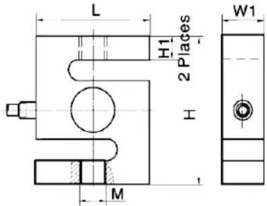
| L [mm] | H [mm] | W1[mm] | H1 [mm] | M [mm] | |
| 1 kN | 50,8 | 76,2 | 20,8 | 15,3 | M10 x 1,5 |
| 2,5 ... 5 kN | 20,8 | 76,2 | 20,8 | 13,6 | M12 x 1,75 |
| 10 kN | 50,8 | 76,2 | 27,2 | 12,1 | M12 x 1,75 |
| 20 ... 50 kN | 76,2 | 101,6 | 27,2 | 20 | M20 x 1,5 |
| 100 kN | 112,78 | 177,8 | 42,93 | - | M30 x 2 |
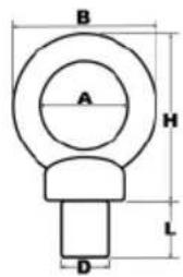
| A [mm] | B [mm] | H [mm] | L [mm] | D [mm] | Max | Weight | |
| 1 kN | 24 | 45 | 45 | 20 | M10 | 0,25 t | 110 g |
| 2,5 kN | 29 | 53 | 53 | 22 | M12 | 0,4 t | 175 g |
| 5 kN | 35 | 62 | 63 | 22 | M12 | 0,7 t | 260 g |
| 10 kN | 39 | 71 | 73 | 22 | M12 | 1 t | 395 g |
| 20 kN ... 50kN | 40 | 72 | 71 | 30 | M20 | 6 t | 450 g |
| 100 kN | 60 | 108 | 109 | 45 | M30 | 12 t | 1700 g |
8 Contact
If you have any questions, suggestions or technical problems, please do not hesitate to contact us. You will find the relevant contact information at the end of this user manual.
9 Disposal
For the disposal of batteries in the EU, the 2006/66/EC directive of the European Parliament applies. Due to the contained pollutants, batteries must not be disposed of as household waste. They must be given to collection points designed for that purpose.
In order to comply with the EU directive 2012/19/EU we take our devices back. We either re-use them or give them to a recycling company which disposes of the devices in line with law.
For countries outside the EU, batteries and devices should be disposed of in accordance with your local waste regulations.
If you have any questions, please contact PCE Instruments.



PCE Instruments contact information
Germany France Spain
PCE Deutschland GmbH PCE Instruments France EURL PCE Ibérica S.L.
Im Langel 26 23, rue de Strasbourg Calle Mayor, 53
D-59872 Meschede 67250 Soultz-Sous-Forets 02500 Tobarra (Albacete)
Unit 11 Southpoint Business Park
Ensign Way, Southampton
Hampshire
United Kingdom, SO31 4RF
Tel: +44 (0) 2380 98703 0
Fax: +44 (0) 2380 98703 9
info@pce-instruments.co.uk
www.pce-instruments.com/english
Italy
PCE Italia s.r.l.
Via Pesciatina 878 / B-Interno 6
55010 Loc. Gragnano Pehlivan Sok. No.6/C
Capannori (Lucca)
Italia
www.pce-instruments.com/turkish
The Netherlands
PCE Brookhuis B.V.
Institutenweg 15
7521 PH Enschede
Nederland
Telefoon: +31 (0)53 737 01 92
info@pcebenelux.nl
www.pce-instruments.com/dutch Fax: +1 (561) 320-9176
info@pce-americas.com
www.pce-instruments.com/us
United States of America
PCE Americas Inc.
1201 Jupiter Park Drive, Suite 8
Jupiter / Palm Beach
33458 FL
USA
Tel: +1 (561) 320-9162
Denmark
PCE Instruments Denmark ApS
Birk Centerpark 40
7400 Herning
Denmark
User manuals in various languages (français, italiano, español, português, nederlands, türk, polski, русский, 中文) can be downloaded here: www.pce-instruments.com Specifications are subject to change without notice.
- Bedienungsanleitung
- User Manual
- Kontakt
- Safety symbols
- Specifications
- Technical specifications
- Delivery contents
- Version with internal cell:
- Version with external cell:
- Optional accessories
- System description
- Device
- Interfaces
- Display
- Function keys
- Getting started
- Power supply
- Settings
- Operation
- Measurement
- Edition with internal sensor:
- Edition with external sensor:
- Maintenance
- Storage
- Appendix: load cell (1 ... 100 kN)
- Contact
- Disposal
- PCE Instruments contact information
- Germany France Spain
- Italy
- The Netherlands
- United States of America
- Denmark
Brand : PCE Instruments
Model : DFG N 50K
Category : Multimeter