LT 15 - Multimeter PCE Instruments - Free user manual and instructions
Find the device manual for free LT 15 PCE Instruments in PDF.


| Product Type | Digital Multimeter with LAN Cable Tester |
| Display | 4000-count LCD |
| AC Voltage Ranges | 400mV, 4V, 40V, 400V, 750V |
| DC Voltage Ranges | 400mV, 4V, 40V, 400V, 750V |
| Resistance Ranges | 400Ω, 4kΩ, 40kΩ, 400kΩ, 4MΩ, 40MΩ |
| Input Impedance | 10MΩ |
| Continuity Test | Audible threshold <25Ω |
| Diode Test | Yes |
| Data Hold | Yes |
| Auto/Manual Ranging | Yes |
| LAN Cable Testing | RJ45/RJ11, Continuity, Open, Short, Miss-wired |
| Remote Unit | Included for remote cable testing |
| Safety Standards | EN 61010-1, EN 61326-1 |
| Multimeter Power | 2x AAA batteries |
| Cable Tester Power | 9V battery |
| Dimensions (approx.) | 150 x 70 x 30 mm |
| Weight (approx.) | 200 g |
| Maintenance | Wipe with damp cloth; no abrasives |
| Storage | Remove battery if unused >60 days |
Frequently Asked Questions - LT 15 PCE Instruments
User questions about LT 15 PCE Instruments
0 question about this device. Answer the ones you know or ask your own.
Ask a new question about this device
Download the instructions for your Multimeter in PDF format for free! Find your manual LT 15 - PCE Instruments and take your electronic device back in hand. On this page are published all the documents necessary for the use of your device. LT 15 by PCE Instruments.
USER MANUAL LT 15 PCE Instruments
Southpoint Business Park
Ensign way
Hampshire / Southampton
United Kingdom, SO31 4RF
From outside UK: +44
Tel: (0) 2380 98703 0
Fax: (0) 2380 98703 9
info@industrial-needs.com
www.pce-instruments.com/english
www.pce-instruments.com
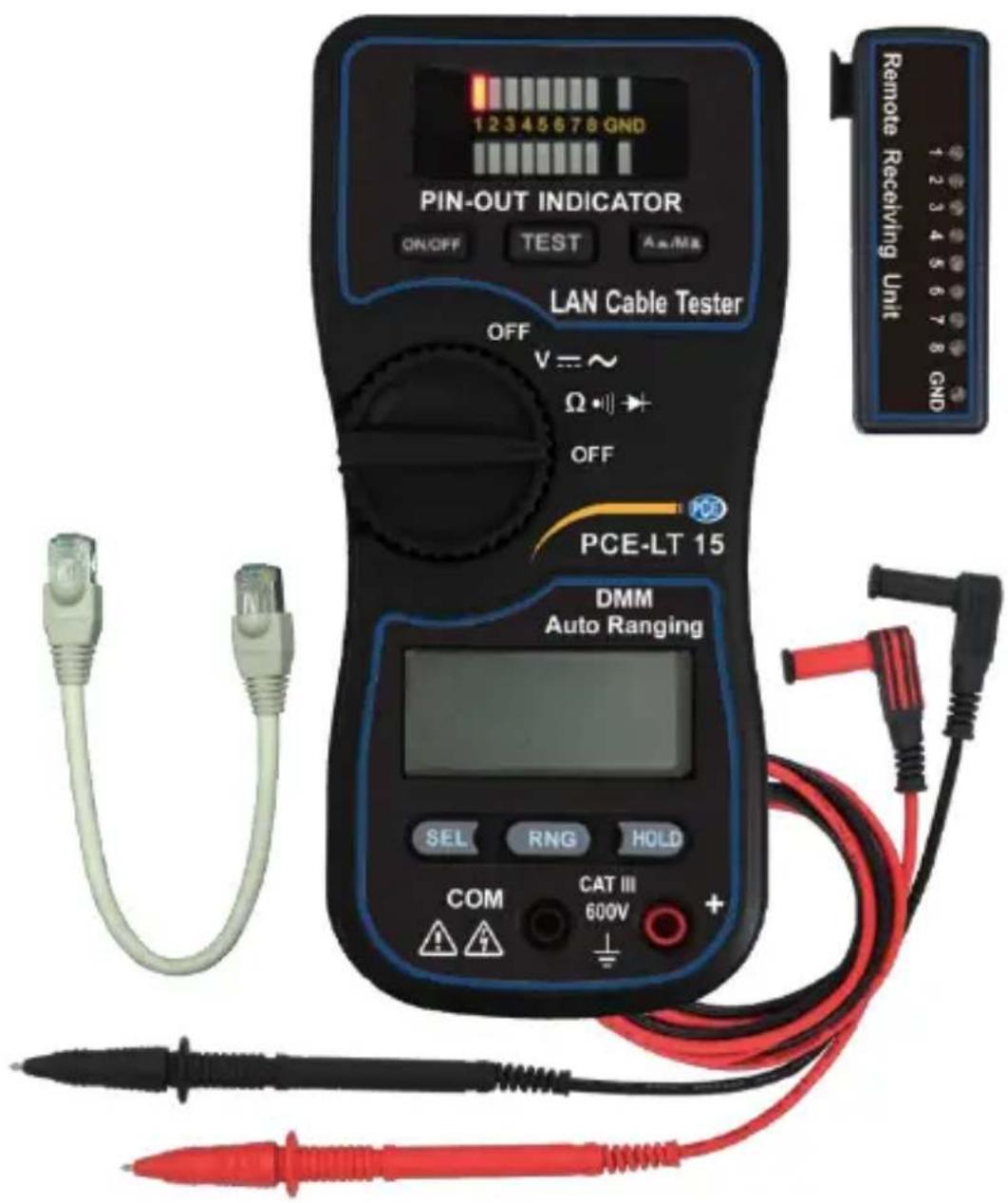
Voltmeter PCE-LT 15
INDEX PAGE
LAN CABLE TESTER
Introduction...... 1
Features.... 1
Instrument Layout.... 2
Operation.... 3-4
Test Result...... 5
DIGITAL MULTIMETER
Features...... 6
Specification.... 6-7
Instrument Layout...... 8
Button Functions.... 9
Measurement.... 10-12
Maintenance.... 13
LAN CABLE TESTER
Introduction
- The Lan cable tester is a newly designed tool that can easily test the correct pin configuration of the RJ45/RJ11 modular cables, 10/100 base-T cable and Token Ring cable etc.
- By comparing one transmitting end and the corresponding receiving end, the Lan cable tester also can test installed cable far away by using the remote receiving unit.
- The LCT provides the variety for wiring check, such as cable continuity, open status, short status and miss-wired.
Features
- Designed for RJ45/RJ11 modular cables, 10/100 base-T cable and Token Ring cable etc.
- The Lan cable tester can verify cable continuity, open, short circuit and miss-wired.
- The remote receiving unit is available for installed cables far away either on the wall plates or on the patch panels.
- Auto and manual scan function.
- Ground wire test.
- Display: LED indication for wire status.
• EN 61010-1 EN 61326-1
Instrument Layout
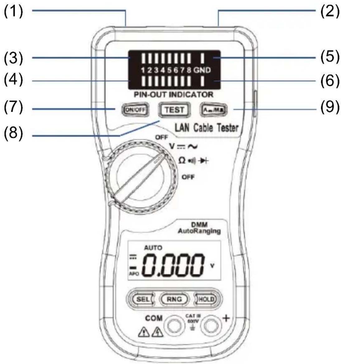
(1) RJ45 jack of sourcing end (OUT).
(2) RJ45 jack of receiving end (IN).
(3) LED indicator of sourcing end.
(4) LED indicator of receiving end.
(5) LED indicator of sourcing end for ground wire test.
(6) LED indicator of receiving end for ground wire test.
(7) Power ON/OFF button.
(8) Test button.
(9) Auto-scan & Manual-scan selection button.
Operation
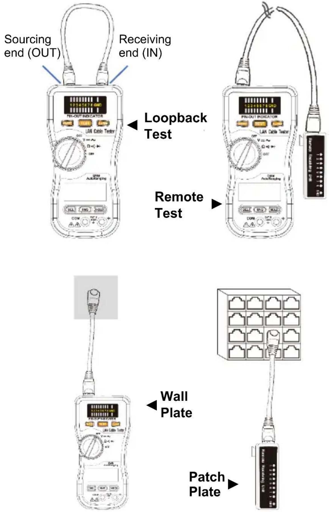
Loopback test
- Plug one end of the testing cable into the RJ45 jack of sourcing end (OUT) on the master unit and another end of the testing cable into the RJ45 jack of receiving end (IN) on the master unit.
- Press the "ON/OFF" button, the master unit will start a sequential scanning process if the master unit is in "auto-scanning" mode.
- Press the "ON/OFF" button, the pin1 LED lamps of the LED indicators will be alight if the master unit is in "manual-scanning" mode.
Note: When the 9V battery power is low, the testing results may not be correct. Please replace with a new 9V battery.
- You can choose an auto-scanning mode or a manual-scanning mode by pressing the "A ▲/M ▲button.
Remote test
- Plug one end of the testing cable into the RJ45 jack of sourcing end (OUT) on the master unit and another end of the testing cable into the RJ45 jack of the remote receiving unit, then make tests.
- Read the testing results from the LED indicator on the remote receiving unit.
Test Result
a. Continuity c. Short
Pin 3 is continued

1 2 3 4 5 6 7 8 GND

Pin 5 and 6 are shorted

1 2 3 4 5 6 7 8 GND

b. Open d. Miss-wired
Pin 4 is opened

1 2 3 4 5 6 7 8 GND

Pin 1 and 7 are

12345678
GND

miss-wired
DIGITAL MULTIMETER
Features
- 4000-count LCD.
-
Fully automatic measurement. Voltage measurement. Resistor measurement.
-
Range change function.
- Select function.
- Data Hold function.
- Continuity check.
- Diode measurement.
- Low battery indication.
- Input impedance:10MΩ.
Specification
AC Voltage
| Range | Resolution | Accuracy |
| 400mV | 0.1mV | ±(1%rdg + 5dgt) |
| 4V | 1mV | |
| 40V | 10mV | |
| 400V | 100mV | |
| 750V | 1V |
Input impedance: 10MΩ
DC Voltage
| Range | Resolution | Accuracy |
| 400mV | 0.1mV | ±(0.5%rdg + 3dgt) |
| 4V | 1mV | |
| 40V | 10mV | |
| 400V | 100mV | |
| 750V | 1V |
Input impedance: 10MΩ
Resistance
| Range | Resolution | Accuracy |
| 400Ω | 0.1Ω | ±(1.2%rdg + 3dgt) |
| 4kΩ | 1Ω | |
| 40kΩ | 10Ω | |
| 400kΩ | 100Ω | |
| 4MΩ | 1kΩ | |
| 40MΩ | 10kΩ | ±(2.0%rdg + 4dgt) |
Overload protection 500V DC
Continuity test
| Range | Audible threshold |
| 400Ω | Less than 25Ω |
Instrument Layout
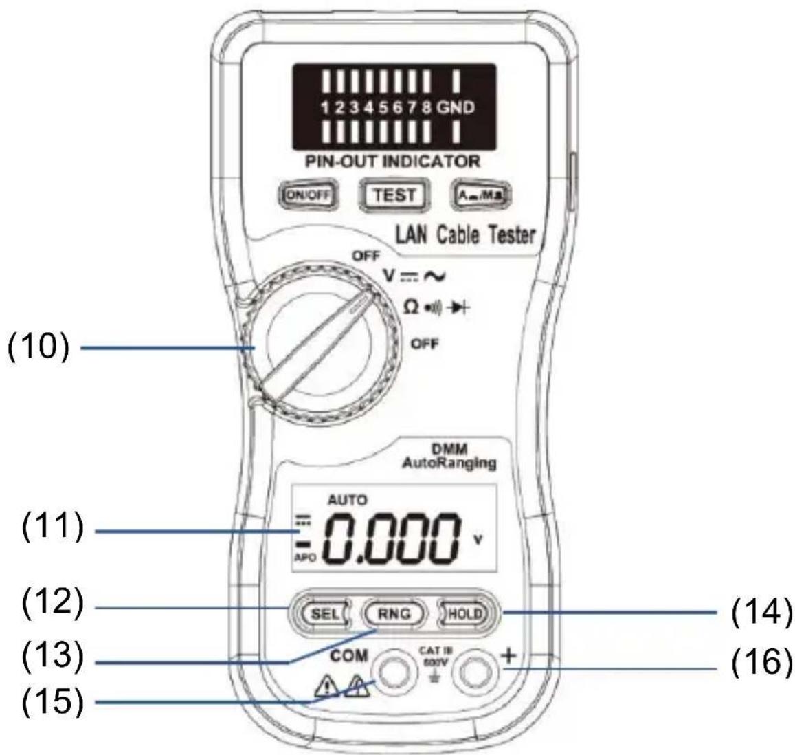
(10) Function rotary switch
(11) LCD
(12) Select button
(13) Range button
(14) Hold button
(15) COM terminal
(16) "+" terminal.
Button Functions
(1) Function rotary switch
The rotary switch selects the function.
(2) LCD
4000-count LCD with LOW BATTERY indication.
(3) Select Button
For AC/DC function selection.
In the resistance + continuity + diode function, press the Select button to select resistance, continuity or diode function.
(4) Range Button
Press the Range button to select the manual range mode. In manual range mode, each time press Range button (less than one second), the range increments and new value is displayed. To exit the manual range mode and return to auto mode, press the RANGE button (More than one second).
(5) HOLD Button
Press the HOLD button (HOLD annunciator turns on) makes the meter stop updating the LCD display. This mode can be nested in most of the special modes.
Enabling HOLD function in automatic mode makes the meter switch to manual mode, but the full scale range remains the same. Hold function can be cancelled by changing the measurement mode, pressing range, or push HOLD again.
(6) COM Terminal
This is the ground input terminal. Use the BLACK test lead to connect.
(7) "+" Terminal
This is positive input terminal for voltage / ohm measurement. Use the RED test lead to connect.
Measurement
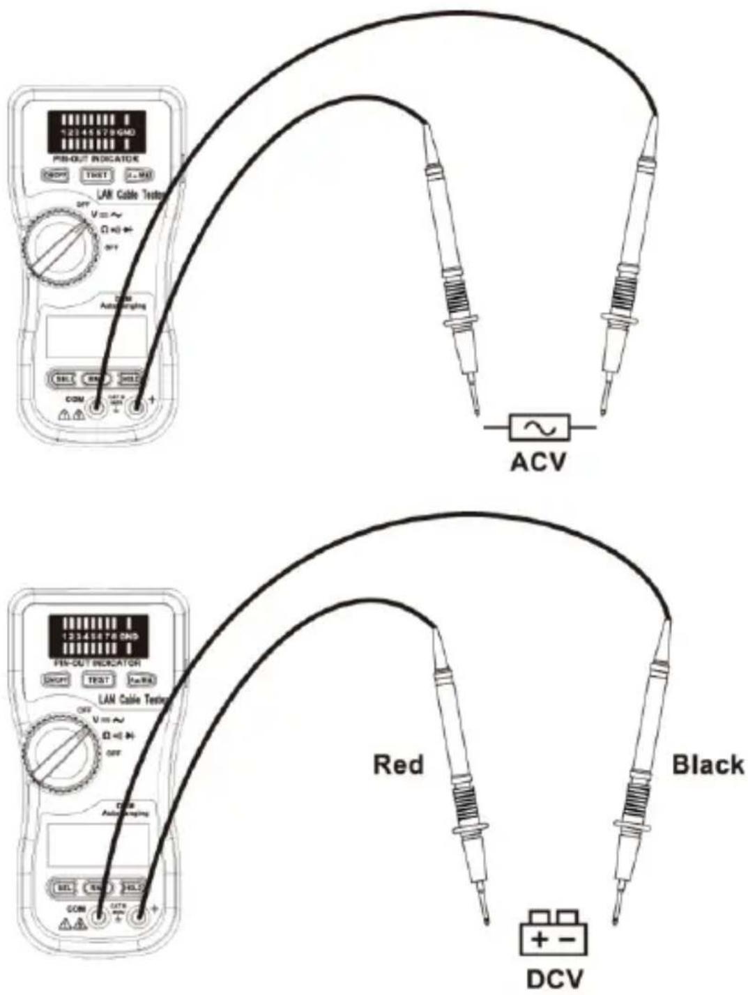
(1) Voltage measurement
Insert the BLACK test lead to COM and the RED test lead to the "+" terminal.
Switch to V function for ACV or DCV
selection. Get the reading directly from the LCD.
(2) Resistance Measurement
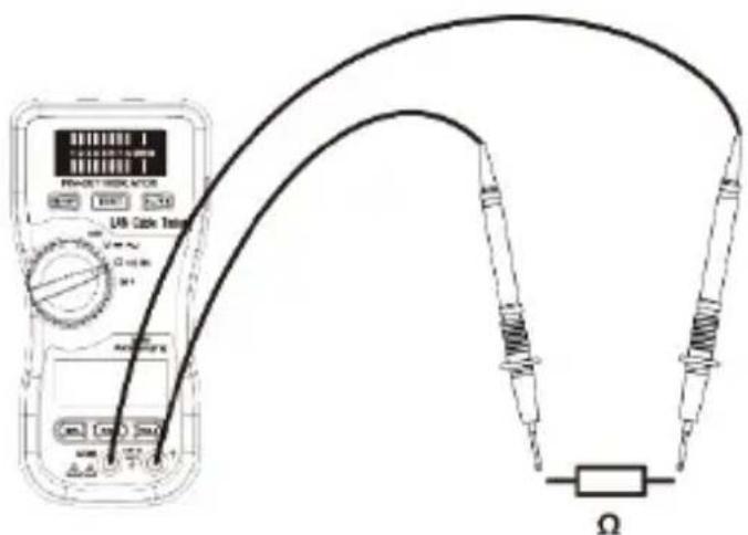
Switch to OHM range and make sure there is no power in the circuit being measured. Insert the BLACK test lead to the COM and the RED test lead to the "+" terminal.
Connect the test leads to the circuit or device under test and get the reading directly from the LCD.
(3) Continuity Check
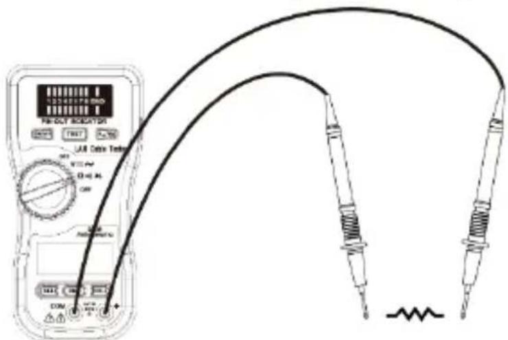
Continuity check shares the same configuration with 400.0Ω manual resistance measurement mode, but with buzzer output to indicate continuity. The buzzer generates a 2kHz sound whenever the digit number less than 25Ω.
Because the cycle time of measurement is only 50ms, the least significant digit will not display.
(4) Diode Measurement
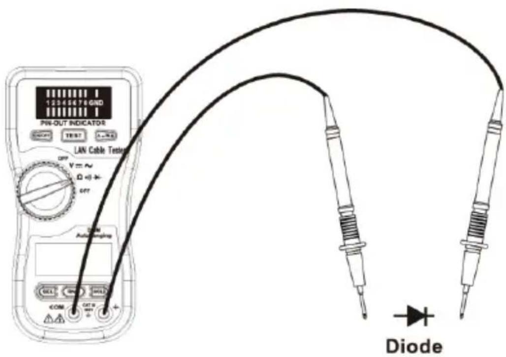
Diode measurement mode shares the same configuration with 4000V manual voltage measurement mode.
If the test circuit is open or the voltage drop between the two ports of the device (diode) under test are larger than 2V, the LCD will show "OL".
The buzzer generates a 2kHz sound whenever the digit number is less than 0.25V. Because the cycle time of measurement is only 50ms, the least significant digit will not display.
Maintenance
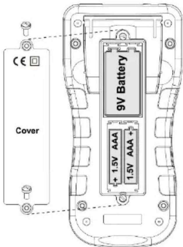
(1) Battery replacement
- Lan cable tester: When press the "ON/OFF" button to start a test, if the LED module of pin-out indicator is too dark and can't work normally, please replace with a new 9V battery.
- Multimeter : Replace two AAA batteries
with the "B" symbol appears at the upper left hand corner of the LCD.
(2) Cleaning and Storage:

WARNING
To avoid electrical shock or damage to the meter, do not get water inside the case.
Periodically wipe the case with a damp cloth and detergent.
Do not use abrasives or solvents.
If the meter is not used for over 60 days, remove the battery for storage.
Brand : PCE Instruments
Model : LT 15
Category : Multimeter