
MCY-MAP0501HT2D - Air conditioner TOSHIBA - Free user manual and instructions
Find the device manual for free MCY-MAP0501HT2D TOSHIBA in PDF.


| Product Type | Split Air Conditioner |
| Model | MCY-MAP0501HT2D |
| Brand | Toshiba |
| Cooling Capacity | 5.0 kW |
| Heating Capacity | 5.5 kW |
| Power Supply | 230V / 50Hz / 1Ph |
| Dimensions (Outdoor Unit) | 800 x 550 x 300 mm |
| Weight (Outdoor Unit) | 35 kg |
| Refrigerant | R32 |
| Inverter Technology | Yes |
| Functions | Cooling, Heating, Dehumidification, Fan, Auto Mode, Sleep Mode, Timer |
| Air Filter | Washable |
| Noise Level (Outdoor) | 50 dB(A) |
| Operating Temperature Range | -15°C to 46°C |
| Energy Efficiency Class | A++ |
| Maintenance | Clean filters every 2 weeks; check condensate drain annually |
| Safety Features | Auto restart, overheat protection, refrigerant leak detection |
| Spare Parts Available | Filter, remote control, fan motor |
| Repairability | Serviceable by certified technician; parts available for 10 years |
| Warranty | 2 years |
Frequently Asked Questions - MCY-MAP0501HT2D TOSHIBA
User questions about MCY-MAP0501HT2D TOSHIBA
0 question about this device. Answer the ones you know or ask your own.
Ask a new question about this device
Download the instructions for your Air conditioner in PDF format for free! Find your manual MCY-MAP0501HT2D - TOSHIBA and take your electronic device back in hand. On this page are published all the documents necessary for the use of your device. MCY-MAP0501HT2D by TOSHIBA.
USER MANUAL MCY-MAP0501HT2D TOSHIBA
MANUEL D'INSTALLATION
INSTALLATIONS-HANDBUCH
natural_image
Line drawing of a dual-chamber air conditioning unit with circular fan patterns (no text or symbols)ADOPTION OF NEW REFRIGERANT
This air conditioner features a new HFC type refrigerant (R-410A) which does not deplete the ozone layer.
Thank you very much for purchasing TOSHIBA Air Conditioner.
- This manual describes the installation method at the outdoor unit side.
- Before installation, please read this Manual thoroughly to perform correct installation.
- For pipe connection for the indoor and outdoor units, flow selector unit Y-shape branching joint or branch header required sold separately. Select it according to the capacity.
- For pipe connection between the outdoor units, T-shape branching joint which is sold separately is required.
UTILISATION DU NOUVEAU REFRIGERANT
ACCESSORY PARTS ....1
SAFETY CAUTION ....1
1 INSTALLATION OF NEW REFRIGERANT AIR CONDITIONER ....3
2 SELECTION OF INSTALLATION PLACE 4
3 REFRIGERANT PIPING....8
4 ELECTRIC WIRING 20
5 INSTALLATION OF OUTDOOR UNIT 26
6 ADDRESS SETUP 27
7 TEST OPERATION....36
8 TROUBLESHOOTING....38
SOMMAIRE
PIECES ACCESSOIRES ....40
MESURES DE SECURITE ....40
1 INSTALLATION DU CLIMATISEUR UTILISANT LE NOUVEAU REFRIGERANT ....42
2 SELECTION DU LIEU D'INSTALLATION 43
3 INSTALLATION DE L'UNITE EXTERIEURE 47
4 INSTALLATION ELECTRIQUE 59
5 INSTALLATION DE L'UNITE EXTERIEURE 65
6 REGLAGE D'ADRESSE 66
7 ESSAI DE FONCTIONNEMENT 75
8 DEPANNAGE 77
INHALT
ZUBEHÖR 79
| MCY-Part name | Q'ty | Shape | Usage | ||
| 0401 type 0 | 501 type 0601 type | ||||
| Installation Manual | 2 | 2 | 2 | — | (Be sure to handover to customers.) |
| Owner's Manual | 1 | 1 | 1 | — | (Be sure to handover to customers.) |
| Joint socket | — | — | 1 |  | Connecting pipes for gas side (∅15.9 to ∅19.1) |
| Protective bush | 1 | 1 | 1 |  | Protection for wiring |
| Guard material for passage part | 1 | 1 | 1 |  | Protection for knockout |
| Drain nipple | 1 | 1 | 1 |  | — |
| Waterproof rubber cap | 1 | 1 | 1 |  | — |
■ The outdoor air conditioner requires the following additional components in order to complete a MiNi-SMMS system. (Indoor unit, remote controller, Y-shape branch joint or branching header.) These items must be selected in accordance to the system capacity.
SAFETY CAUTION
- Please read this “Safety Cautions” thoroughly before installation to install the air conditioner correctly.
- The important contents concerned to the safety are described in the “Safety Cautions”. Be sure to keep them. For Indications and their meanings, see the following description.
■Explanation of indications
WARNING
Indicates possibilities that a death or serious injury of personnel is caused by an incorrect handling.
CAUTION
Indicates contents that an injury (*1) or property damage (*2) only may be caused when an incorrect work has been executed.
*1: "Injury" means a hurt, a burn, or an electric shock which does not require hospitalization or a long-term going to the hospital.
*2 : "Property damage" means an enlarged damage concerned to property, or breakage of materials.
- After the installation work has been completed, perform a trial operation to check for possible problems.
Follow the owner's manual and explain to the customer how to use and maintain the unit.
WARNING
Ask an authorized dealer or qualified installation professional to install/maintain the air conditioner.
Inappropriate installation may result in water leakage, electric shock or fire.
Using the tool or piping materials exclusive to R410A, install the air conditioner surely according to this Installation Manual.
The pressure of the used HFC system R410A refrigerant is higher approx. 1.6 times of that of the former refrigerant. If the exclusive piping materials are not used, or there is imperfection in installation, a crack or an injury is caused and also a water leak, an electric shock, or a fire may be caused.
Take measures so that the refrigerant does not exceed the limit concentration even if it leaks when installing the air conditioner in a small room.
For the measures not to exceed the limit of concentration, contact the dealer. If the refrigerant leaks and it exceeds the limit of concentration, an accident of oxygen shortage is caused.
The location of the installation must be able to protect from abnormal environmental conditions, such as earthquake and typhoons.
An incorrect installation will cause a risk of unit movement resulting in a possible accident.
Perform a specified installation work against a strong wind such as typhoon or earthquake.
If the air conditioner is imperfectly installed, an accident by falling or dropping may be caused.
If refrigerant gas leaks during the installation work, ventilate the room immediately.
If the leaked refrigerant gas comes into contact with fire, noxious gas may generate.
After the installation work, confirm that refrigerant gas does not leak.
If refrigerant gas leaks onto the room and flows near to a source of fire, noxious gas maybe generated.
Never recover refrigerant in the outdoor unit.
Be sure to use a refrigerant recovery device to recover refrigerant in reinstallation or repair work.
Recovery of refrigerant in the outdoor unit is unavailable; otherwise a serious accident such as crack or human injury is caused.
Electrical work must be performed by a qualified electrician in accordance with the installation manual. Ensure the air conditioner uses a designated power supply.
An insufficient power supply capacity or inappropriate installation may cause fire.
When connecting the installation wiring, be sure that all fixing terminals are securely fixed.
Ensure earth connection.
If earth wiring is poor, this will cause risk of electric shock.
If grounding is incomplete, an electric shock is caused.
CAUTION
Ensure that the unit is to placed where there is no risk of flammable gases.
If flammable gases accumulate around the outside of the unit combustion may occur.
Ensure the outdoor unit is fixed to the base, to prevent movement of the unit.
Ensure an electrical leakage breaker is fitted. This is to prevent the risk of electric shock.
Using a torque wrench, tighten the flare nuts to the specified torque setting.
Over tightening will risk damaging the flare nut, and may cause refrigerant to leak after a period of time.
This air conditioner adopts the new HFC refrigerant (R410A) which does not deplete the ozone layer.
- R410A refrigerant is apt to be affected by impurity such as water, oxidizing membrane, or oils because the pressure of R410A refrigerant is higher than that of the former refrigerant by approx. 1.6 times. Accompanied with adoption of the new refrigerant, refrigerating oil has been also changed. Therefore pay attention so that water, dust, former refrigerant, or refrigerating oil does not enter into the refrigerating cycle of the new refrigerant air conditioner during installation work.
- To prevent from mixing of refrigerant or refrigerating oil, the size of charge port of the main unit or connecting section of installation tool differs from that of the air conditioner for the former refrigerant. Accordingly the exclusive tools are required for the new refrigerant (R410A) as shown below.
- For connecting pipes, use the new and clean piping materials so that water or dust does not enter.
Required tools and cautions on handling
It is necessary to prepare the tools and parts as described below for the installation work.
The tools and parts which will be newly prepared in the following items should be restricted to the exclusive use.
Explanation of symbols
- : Newly prepared (It is necessary to use it properly exclusive to R410A separated from those for R22 or R407C.) O: Former tool is available.
| Used tools | Usage | Proper use of tools/parts |
| Gauge manifold | Vacuuming or charging of refrigerant and operation check | ● Newly prepared, Exclusive to R410A |
| Charging hose | ● Newly prepared, Exclusive to R410A | |
| Charging cylinder | Charges refrigerant | Unusable (Use the Refrigerant charging balance.) |
| Gas leak detector | Checks gas leak | ● Newly prepared |
| Vacuum pump | Vacuum drying | Usable if a counter-flow preventive adapter is attached |
| Vacuum pump with counter-flow preventive adapter | Vacuum drying | ○ : R22 (Existing article) |
| Flare tool | Flare processing of pipes | ○ : Usable by adjusting size |
| Bender | Bending processing of pipes | ○ : R22 (Existing article) |
| Refrigerant recovery device | Recovers refrigerant | ● Exclusive to R410A |
| Torque wrench | Tightens flare nut | ● Newly prepared, exclusive to ∅12.7mm and ∅15.9mm |
| Pipe cutter | Cuts pipes | ○ : R22 (Existing article) |
| Refrigerant cylinder | Charges refrigerant | ● Exclusive to R410AID : Refrigerant name entered |
| Welding machine/Nitrogen gas cylinder | Welding of pipes | ○ : R22 (Existing article) |
| Refrigerant charging balance | Charges refrigerant | ○ : R22 (Existing article) |
2 SELECTION OF INSTALLATION PLACE
WARNING
The installation of the air conditioning unit must be positioned in a location that can sufficiently support its weight and give protection against adverse environmental conditions.
Failure to do so may result in unit damage and possible human injury.
CAUTION
Ensure that the unit is to placed where there is no risk of flammable gases.
If flammable gases accumulate around the outside of the unit combustion may occur.
Ensure the outdoor unit is fixed to the base, to prevent movement of the unit.
Obtain permission from the customer to install the unit in a location that satisfies the following requirements :
- A location that permits level installation of the unit.
- A location that provides enough space to service the unit safely
- A location where water draining from the unit will not pose a problem
Apply electric insulation between metal section of the building and metal section of the air conditioner in conformance with the Local Regulation.
Avoid installing in the following places.
- Place exposed to air with high salt content (seaside area), or place exposed to large quantities of sulfide gas (hot spring). (Should the unit be used in these places, special protective measures are needed.)
- Place exposed to oil, vapor, oil smoke or corrosive gas.
- Place where organic solvent is used nearby.
- Place close to a machine generating high frequency.
- Place where the discharged air blows directly into the window of the neighboring house. (For outdoor unit)
- Place where noise of the outdoor unit is easily transmitted.
(When installing the air conditioner on the boundary with the neighbor, pay due attention to the level of noise.) - Place with poor ventilation.
(Especially in Concealed duct type indoor unit, before air ducting work, check whether value of air volume, static pressure and duct resistance are correct.)
Equipments
| Equivalent HP | Inverter unit | ||
| Outdoor unit capacity type | 0401 type 05 | 501 type 0601 | type |
| 4 HP 5 HP | 6 HP | ||
| Cooling capacity (kW) | 12.1 14.0 | 15.5 | |
| Heating capacity (kW) | 12.5 16.0 | 18.0 | |
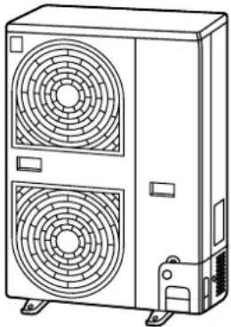
| Appearance |
 |
AInstallation space
Considering functions, reserve space necessary for installation work and servicing.
Installation place
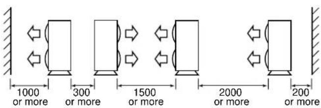
- A place which provides a specified space around the outdoor unit.
- A place where the operation noise and discharged air are not given to your neighbors.
• A place that is not exposed to a strong wind.
• A place that does not block a passage. - When the outdoor unit is installed in an elevated position, be sure to secure its feet.
- There must be sufficient space for carrying in the unit.
- A place where the drain water does not make any problem.
CAUTION
- Install the outdoor unit at a place where discharge air is not blocked.
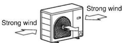
- When an outdoor unit is installed in a place that is always exposed to a strong wind like a coast or on a high story of a building, secure a normal fan operation by using a duct or a wind shield.
- When installing the outdoor unit in a place that is constantly exposed to a strong wind such as the upper stairs or rooftop of a building, apply the windproof measures referring to the following examples.
1) Install the unit so that its discharge port faces
to the wall of the building. Keep a distance 500 mm or more between the unit and the wall surface.

2) Supposing the wind direction during the operation season of the air conditioner, install the unit so that the discharge port is set at right angle to the wind direction.
- Installation in the following places may result in some troubles. Do not install the unit in such places below.
• A place full of machine oil.
• A place full of sulfuric gas.
- A place where high-frequency radio waves are likely to be generated as from audio equipment, welders, and medical equipment.
Necessary space for installation
Obstacle at rear side
[Upper side is free]
- Single unit installation
![TOSHIBA MCY-MAP0501HT2D - [Upper side is free] - 1](/content/2026/05/1038534/images/7b571c55527f2a829a08665fbdc7ea32e003b7384ffab68cfafcee5b81817687.jpg)
- Obstacles at both right and left sides.

- Serial installation of two or more units
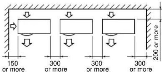
The height of the obstacle should be lower than the height of the outdoor unit.
[Obstacle also at the upper side]

Obstacle at front side
[Upper side is free]
- Single unit installation

- Serial installation of two or more units
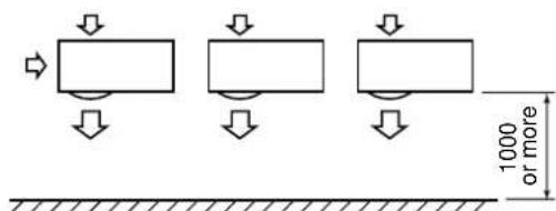
[Obstacle also at the upper side]

Obstacles at both front and rear sides
Open the upper side and both right and left sides. The height of obstacle at both front and rear side, should be lower than the height of the outdoor unit.
[Standard installation]
- Single unit installation

- Serial installation of two or more units

Serial installation at front and rear sides
Open the upper side and both right and left sides. The height of obstacle at both front and rear sides should be lower than the height of the outdoor unit.
[Standard installation]
Installation of outdoor unit
- Before installation, check strength and horizontally of the base so that abnormal sound does not generate.
- According to the following base diagram, fix the base firmly with the anchor bolts. (Anchor bolt, nut: M10 x 4 pairs)

Set the out margin of the anchor bolt to 15mm or less.

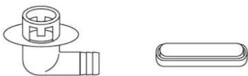
- In case of draining through the drain hose, attach the following drain nipple and the waterproof rubber cap, and use the drain hose (Inner diam.: 16mm) sold on the market. And also seal the screws securely with silicone material, etc. so that water does not drop down. Some conditions may cause dewing or dripping of water.
natural_image
Technical line drawing of a pipe fitting and a rectangular component (no text or symbols)Drain nipple Waterproof rubber cap
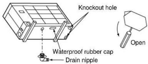
- When there is a possibility of freezing of drain at the cold district or a snowfall area, be careful for drainage ability of drain. The drainage ability increases when a knockout hole on the base plate is opened. (Open the knockout hole to outside using a screwdriver, etc.)
Refrigerant piping connection
CAUTION
TAKE NOTICE THESE IMPORTANT 4 POINTS BELOW FOR PIPING WORK
- Keep dust and moisture away from inside the connecting pipes.
- Tightly connect the connection between pipes and the unit.
- Evacuate the air in the connecting pipes using VACUUM PUMP.
- Check gas leak at connected points.
For reference
If a heating operation would be continuously performed for a long time under the condition that the outdoor temperature is 0^ C or lower, draining of defrosted water may be difficult due to freezing of the bottom plate, resulting in a trouble of the cabinet or fan.
It is recommended to procure an anti-freeze heater locally for a safety installation of the air conditioner. For details, contact the dealer.
Knockout of pipe cover
Knockout procedure
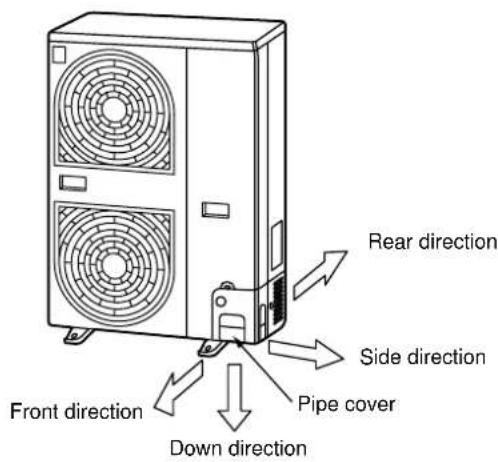
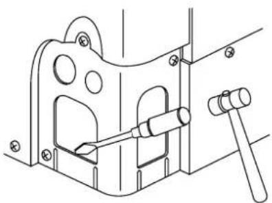
- The indoor/outdoor connecting pipes can be connected to 4 directions.
Take off the knockout part of the pipe cover in which pipes or wires pass through the base plate. - As shown in the figure, do not remove the pipe cover from the cabinet so that the knockout hole can be easily punched. To knock out, it is easily taken off by hands by punching a position at the lower side of 3 connected parts with screwdriver along the guide line.
• After marking the knockout hole, remove the burr and mount the attached protective bush and guard material for pass-through part in order to protect pipes and wires.
After connecting the pipes, be sure to mount the pipe cover. The pipe cover is easily mounted by cutting off the slit at the lower part of the pipe cover.
natural_image
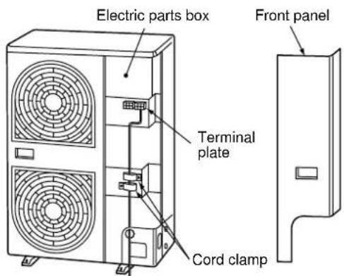
Technical line drawing of a mechanical clamp or bracket assembly (no text or symbols)How to remove the front panel
- Remove screws of the front panel.
- Pull the front panel downward.
Removing the front panel, the electric parts appear at the front side.
- The metal pipes are attachable to the piping holes. If the size of the used power pipe does not match with the hole, adjust the hole size to match with pipe size.
- Be sure to fix the power cable and indoor/outdoor connecting cable with bundling band sold on the market so that they do not make contact with the compressor and discharge pipe.
(Temperature of the compressor and discharge pipe becomes high.)
In order to avoid the force applied to on the connecting section, be sure to fix the cables to the cord clamps provided on the pipe valve fixing plate and the electric parts box.
WARNING
If the refrigerant gas leaks during installation work, ventilate the room immediately.
If the leaked refrigerant gas comes into contact with a source of fire, noxious gas maybe generated.
After installation work is complete, check refrigerant gas does not leak.
If the refrigerant leaks into the room and comes into contact with a naked flame, noxious gas maybe generated.
Pipe forming/End positioning
Flaring
- Cut the pipe with a pipe cutter.

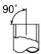
NO GOODOK
Obliquity

Roughness

Warp

- Insert a flare nut into the pipe, and flare the pipe.
As the flaring sizes of R410A differ from those of refrigerant R22, the flare tools newly manufactured for R410A are recommended.
However, the conventional tools can be used by adjusting projection margin of the copper pipe.
- Flaring size : A (Unit : mm)

| Outer dia. of copper pipe | A+0-0.4 | |
| R410A R22 | ||
| 9.5 | 13.2 13.0 | |
| 15.9 | 19.7 19.4 | |
* In case of flaring for R410A with the conventional flare tool, pull it out approx. 0.5 mm more than that of R22 to adjust to the specified flare size.
The copper pipe gauge is useful for adjusting projection margin size.
- Projection margin in flaring : B (Unit : mm)
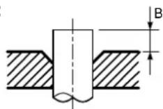
Rigid (Clutch type)
| Outer dia. of copper pipe | R410A tool used | Conventional tool used | ||
| R410A R22 | R410A R22 | |||
| 9.5 | 0 to 0.5 (Same as left) | 1.0 to 1.5 0.5 to 1.0 | ||
| 15.9 | 0 to 0.5 (Same as left) | 1.0 to 1.5 0.5 to 1.0 | ||
Imperial (Wing nut type)
| Outer dia. of copper pipe | R410A R22 | |
| 9.5 | 1.5 to 2.0 1.0 | to 1.5 |
| 15.9 | 2.0 to 2.5 1.5 | to 2.0 |
Tightening of connecting part
(Unit: N·m)
| Outer dia. of copper pipe | Tightening torque |
| 9.5 mm (diam.) | 33 to 42 (3.3 to 4.2 kgf•m) |
| 15.9 mm (diam.) | 68 to 82 (6.8 to 8.2 kgf•m) |
- Align the centers of the connecting pipes and tighten the flare nut strong as far as possible with your fingers.
Then fix the nut with a spanner and tighten it with torque wrench as shown in the figure.
Half union or packed valve Flare nut

Fix with spanner.
Tighten with torque wrench.
- As shown in the figure, be sure to use a double spanner to loosen or tighten the flare nut of the valve at gas side. If using a single spanner, the nut cannot be tightened with necessary tightening torque.
On the contrary, use a single spanner to loosen or tighten the flare nut of the valve at liquid side.
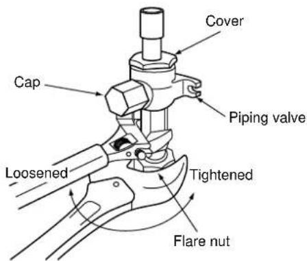
Valve at gas side
REQUIREMENT
-
Do not put the spanner on the cap. The valve may be broken.
-
If applying excessive torque, the nut may be broken according to some installation conditions.
• After the installation work, be sure to check gas leak of connecting part of the pipes with nitrogen.

- Pressure of R410A is higher than that of R22 (Approx. 1.6 times). Therefore, using a torque wrench, tighten the flare pipe connecting sections which connect the indoor/outdoor units at the specified tightening torque. Incomplete connections may cause not only a gas leak, but also a trouble of the refrigeration cycle.
Do not apply refrigerating machine oil to the flared surface.
Pipe connecting method of valve at gas side
| Outdoor unit capacity type | Gas pipe diameter | Pipe connecting method of valve at gas side |
| 0401 type0501 type | ∅15.9 | Connect ∅15.9 pipe with flaring.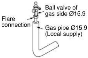 |
| 0601 type | ∅19.1 | For braze connection of ∅19.1 gas pipe, refer to the following method.1. Form the pipe so that the end part of the pipe will be out from the outdoor unit along the taking-out direction of the pipe.The ∅15.9 gas pipe to be supplied locally.2. Using the joint socket (Accessory), connect with braze ∅15.9 gas pipe and ∅19.1 gas pipe at outside of the outdoor unit.3. After connecting the pipes, apply thermal insulation process to the gas pipe until near the valve.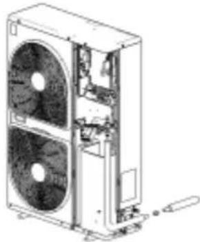 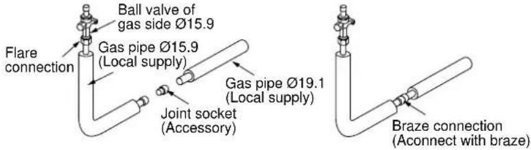 |
• Coupling size of brazed pipe
| Connected section | |
| External size Internal size | |
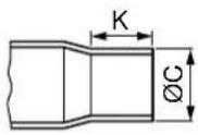 |  |
(Unit: mm)
| Standard outer dia. of connected copper pipe | Connected section | Min. thickness of coupling | ||||
| External size Internal size | Min. depth of insertion | Oval value | ||||
| Standard outer dia. (Allowable difference) | ||||||
| C | F | K | G | |||
| 6.35 6.35 ( ± 0.03 ) 6.45 ( | ^+0.04_-0.02 ) 7 | 6 0.06 or | less 0.50 | |||
| 9.52 9.52 ( ± 0.03 ) 9.62 ( | ^+0.04_-0.02 ) 8 | 7 0.08 or | less 0.60 | |||
| 12.70 12.70 ( ± 0.03 ) 12.81 ( | ^+0.04_-0.02 ) 9 | 8 0.10 or | less 0.70 | |||
| 15.88 15.88 ( ± 0.03 ) 16.00 ( | ^+0.04_-0.02 ) 9 | 8 0.13 or | less 0.80 | |||
| 19.05 19.05 ( ± 0.03 ) 19.19 ( | ^+0.03_-0.03 ) 11 10 | 0 | 15 or less 0.80 | |||
Selection of pipe materials and size
- Selection of pipe material
Material: Phosphorus deoxidation seam-less pipe
- Capacity code of indoor and outdoor units
- For the indoor unit, the capacity code is decided at each capacity rank.
- The capacity codes of the outdoor units are decided at each capacity rank.
The maximum No. of connectable indoor unit and the total value of capacity codes of the indoor units are also decided.
Minimum wall thickness for R410A application
| Soft | Harf Hard or Hard | OD (Inch) | OD (mm) | Minimum wall thickness (mm) |
| OK | OK | 1/4" | 6.35 | 0.80 |
| OK | OK | 3/8" | 9.52 | 0.80 |
| OK | OK | 1/2" | 12.70 | 0.80 |
| OK | OK | 5/8" | 15.88 | 1.00 |
| NG * | OK | 3/4" | 19.05 | 1.00 |
* If the pipe size is ∅19.0 or more, use a suitable material.
Table 1
| Indoor unit capacity type | Capacity code | |
| Equivalent to HP | Equivalent to capacity | |
| 007 type | 0.8 | 2.2 |
| 009 type | 1 | 2.8 |
| 012 type | 1.25 | 3.6 |
| 015 type | 1.7 | 4.5 |
| 018 type | 2 | 5.6 |
| 024 type | 2.5 | 7.1 |
| 027 type | 3 | 8 |
| 030 type | 3.2 | 9 |
| 036 type | 4 | 11.2 |
| 048 type | 5 | 14 |
Table 2
| Outdoor unit capacity type | Capacity code | No. of connectable indoor units | Total capacity code of connectable indoor units | |
| Equivalent to HP | Min. (HP) | Max. (HP) | ||
| 0401 type | 4 | 6 | 3.2 | 5.2 |
| 0501 type | 5 | 8 | 4.0 | 6.5 |
| 0601 type | 6 | 9 | 4.8 | 7.8 |
Selection of refrigerant piping

flowchart
graph TD
    A["Main pipe"] -->|1| B["1st branching section"]
    B --> C["Branch header"]
    C --> D["Indoor unit"]
    D --> E["Y-shape branch joint"]
    E --> F["Branching pipe"]
    F --> G["Outdoor unit"]
    H["Gas pipe"] --> I["Main pipe"]
    J["Liquid pipe"] --> K["1st branching section"]
    K --> L["Branching pipe"]
    L --> M["Branch header"]
    M --> N["Indoor unit"]
    O["3"] --> P["3"]
    P --> Q["3"]
    Q --> R["3"]
    R --> S["3"]
    S --> T["3"]
    T --> U["3"]
    U --> V["3"]
    V --> W["3"]
    W --> X["3"]
    X --> Y["3"]
    Y --> Z["3"]
    Z --> AA["3"]
    AA --> AB["3"]
    AB --> AC["3"]
    AC --> AD["3"]
    AD --> AE["3"]
    AE --> AF["3"]
    AF --> AG["3"]
    AG --> AH["3"]
    AH --> AI["3"]
    AI --> AJ["3"]
    AJ --> AK["3"]
    AK --> AL["3"]
    AL --> AM["3"]
    AM --> AN["3"]
    AN --> AO["3"]
| No. | Piping parts Name Selection of pipe size | ||||
| 1 | Outdoor unit↓1st branching section | Main pipe | Size of main pipe | ||
| Outdoor unit capacity type Gas pipe | Liquid pipe | ||||
| 0401 type 15.9 9.5 | |||||
| 0501 type 15.9 9.5 | |||||
| 0601 type 19.1 9.5 | |||||
| 2 | Branching section↓Branching section | Branching pipe | Pipe size between branching sections | ||
| Total capacity codes of indoor units at down stream side | Gas pipe Liquid pipe | ||||
| Equivalent to HP | |||||
| Below 2.8 12.7 9.5 | |||||
| 2.8 to below 6.4 15.9 9.5 | |||||
| 6.4 to below 7.2 19.1 9.5 | |||||
| Note) If the total capacity code value of indoor units exceeds that of the outdoor units, apply the capacity code of outdoor units. | |||||
| 3 | Branching section↓Indoor unit | Indoor unit connecting pipe | Connecting pipe size of indoor unit | ||
| Indoor unit capacity type Gas pipe | Liquid pipe | ||||
| 007, 009, 012 type 9.5 6.4 | |||||
| 015, 018 type 12.7 6.4 | |||||
| 024, 030, 036, 048 type 15.9 9.5 | |||||
| 4 | Branching section | Y-shape branch joint Branch header | Selection of branching section | ||
| Total capacity codes of indoor units at down stream side | Model name | ||||
| Equivalent to HP | |||||
| Y-shape branch joint | Below 6.4 | RBM-BY53E | |||
| 6.4 or more and up to 7.8 | RBM-BY103E | ||||
| Branch header | For 4 branches | Up to 7.8 | |||
| For 8 branches | Up to 7.8 | ||||
| Note) *1: When using a Y-shape branching joint for the 1st branch, select according to capacity code of the outdoor unit.*2: For 1 line after branching header indoor units with a maximum capacity code of 6.0 in total can be connected. | |||||
| Outdoor unit capacity type Gas pipe Liquid pipe | |
| 0401 type 15.9 9.5 | |
| 0501 type 15.9 9.5 | |
| 0601 type 19.1 9.5 |
| Total capacity codes of indoor units at down stream side | Gas pipe Liquid pipe |
| Equivalent to HP | |
| Below 2.8 12.7 9.5 | |
| 2.8 to below 6.4 15.9 9.5 | |
| 6.4 to below 7.2 19.1 9.5 |
| Indoor unit capacity type Gas pipe | Liquid pipe | |
| 007, 009, 012 type 9.5 6.4 | ||
| 015, 018 type 12.7 6.4 | ||
| 024, 030, 036, 048 type 15.9 9.5 |
| Total capacity codes of indoor units at down stream side | Model name | ||
| Equivalent to HP | |||
| Y-shape branch joint | Below 6.4 | RBM-BY53E | |
| 6.4 or more and up to 7.8 | RBM-BY103E | ||
| Branch header | For 4 branches | Up to 7.8 | RBM-HY1043E |
| For 8 branches | Up to 7.8 | RBM-HY1083E | |
Selection of refrigerant piping for quiet place (with PMV Kit)

flowchart
graph TD
    A["Outdoor unit"] -->|Gas pipe| B["Main pipe"]
    A -->|Liquid pipe| C["1st branching section"]
    C --> D["Branching pipe ④"]
    C --> E["Branch header ④"]
    D --> F["Branching pipe ②"]
    E --> G["Branch header ④"]
    F --> H["Branching pipe ③"]
    G --> I["Branching pipe ⑤"]
    H --> J["Y-shape branch joint ④"]
    I --> K["Y-shape branch joint ②"]
    J --> L["PMV Kit"]
    K --> M["PMV Kit"]
    L --> N["Indoor unit"]
    M --> O["Indoor unit"]
    N --> P["Indoor unit"]
    O --> Q["Indoor unit"]
| No. | Piping parts Name Selection of pipe size | |||||
| 1 | Outdoor unit↓1st branching section | Main pipe | Size of main pipe | |||
| Outdoor unit capacity type Gas pipe Liquid pipe | ||||||
| 0401 type 15.9 9.5 | ||||||
| 0501 type 15.9 9.5 | ||||||
| 0601 type 19.1 9.5 | ||||||
| 2 | Branching section↓Branching section | Branching pipe | Pipe size between branching sections | |||
| Total capacity codes of indoor units at down stream side | Gas pipe Liquid pipe | |||||
| Equivalent to HP | ||||||
| Below 2.8 12.7 9.5 | ||||||
| 2.8 to below 6.4 15.9 9.5 | ||||||
| 6.4 to below 7.2 19.1 9.5 | ||||||
| Note) If the total capacity code value of indoor units exceeds that of the outdoor units, apply the capacity code of outdoor units. | ||||||
| 3 | Branching section↓Indoor unit | Indoor unit connecting pipe | Connecting pipe size of indoor unit | |||
| Indoor unit capacity type | Gas pipe Liquid pipe | |||||
| 007, 009, 012 type | 9.5 | 6.4 | ||||
| 015, 018 type | 12.7 6.4 | |||||
| 024, 030, 036, 048 type | 15.9 9.5 | |||||
| 4 | Branching section | Y-shape branch joint Branch header | Selection of branching section | |||
| Total capacity codes of indoor units at down stream side | Model name | |||||
| Equivalent to HP | ||||||
| Y-shape branch joint | Below 6.4 | RBM-BY53E | ||||
| 6.4 or more and up to 7.8 | RBM-BY103E | |||||
| Branch header | For 4 branches | Up to 7.8 RBM-HY1043E | ||||
| For 8 branches | Up to 7.8 RBM-HY1083E | |||||
| Note) *1: When using a Y-shape branching joint for the 1st branch, select according to capacity code of the outdoor unit.*2: For 1 line after branching header indoor units with a maximum capacity code of 6.0 in total can be connected. | ||||||
| 5 | PMV Kit | PMV Kit | Selection of PMV Kit | |||
| Indoor unit capacity type | Model name | |||||
| 007, 009, 012 type | RBM-PMV0361E | |||||
| 015, 018, 024 type | RBM-PMV0901E | |||||
| Outdoor unit capacity type Gas pipe Liquid pipe | ||
| 0401 type 15.9 9.5 | ||
| 0501 type 15.9 9.5 | ||
| 0601 type 19.1 9.5 | ||
| Total capacity codes of indoor units at down stream side | Gas pipe Liquid pipe |
| Equivalent to HP | |
| Below 2.8 12.7 9.5 | |
| 2.8 to below 6.4 15.9 9.5 | |
| 6.4 to below 7.2 19.1 9.5 |
| Indoor unit capacity type | Gas pipe Liquid pipe | |
| 007, 009, 012 type | 9.5 | 6.4 |
| 015, 018 type | 12.7 6.4 | |
| 024, 030, 036, 048 type | 15.9 9.5 | |
| Total capacity codes of indoor units at down stream side | Model name | ||
| Equivalent to HP | |||
| Y-shape branch joint | Below 6.4 | RBM-BY53E | |
| 6.4 or more and up to 7.8 | RBM-BY103E | ||
| Branch header | For 4 branches | Up to 7.8 RBM-HY1043E | |
| For 8 branches | Up to 7.8 RBM-HY1083E | ||
| *2: For 1 line after branching header indoor units with a maximum capacity code of 6.0 in total can be connected. |
| election of PMV Kit |
| Indoor unit capacity type | Model name |
| 007, 009, 012 type | RBM-PMV0361E |
| 015, 018, 024 type | RBM-PMV0901E |
Allowable length/height difference of refrigerant piping
Outdoor unit
Main pipe L1
Branching pipe L2
Branch header
1st branching section
a b c d
Height difference between indoor and outdoor units H1
Branching pipe L3
Indoor unit
Equivalent length corresponded to farthest piping L
Equivalent length corresponded to farthest piping after 1st branching Li
Height difference between indoor units H2
L4
e f g
Y-shape branch joint
A*1
Allowable value Piping section
Total extension of pipe (Liquid pipe, real length) 180 m L1 + L2 + L3 + L4 + a + b + c + d + e + f + g
Real length 100 m
Furthest piping length L ( *1)
Equivalent length 125 m
L1 + L3 + L4 + g
Piping
Length
Max. equivalent length of main pipe 65 m L1
Equivalent length of furthest piping from 1^st branching Li ( *1)
35 m L3 + L4 + g
Max. real length of indoor unit connecting pipe 15 m a, b, c, d, e, f. g
Height Difference
Height between indoor and outdoor units H1
Upper outdoor unit 30 m —
Lower outdoor unit 20 m —
Height between indoor units H2 15 m —
*1 : Furthest indoor unit from 1 ^st branch to be named “A”.
Allowable length/height difference of refrigerant piping for quiet places (with PMV Kit)

flowchart
graph TD
    A["Outdoor unit"] -->|Main pipe L1| B["Branching pipe L2"]
    B --> C["Branch header"]
    C --> D["PMV Kit"]
    D --> E["Indoor unit"]
    E --> F["Equivalent length corresponded to farthest piping L"]
    F --> G["Y-shape branch joint"]
    G --> H["L4"]
    H --> I["Ground"]
    style A fill:#f9f,stroke:#333
    style D fill:#ccf,stroke:#333
    style E fill:#cfc,stroke:#333
    style F fill:#fcc,stroke:#333
    style G fill:#cff,stroke:#333
    style H fill:#ffc,stroke:#333
    style I fill:#fcf,stroke:#333
| Allowable value | Piping section | |||
| Piping Length | Total extension of pipe (Liquid pipe, real length) | 150 m | L1 + L2 + L3 + L4+a + b + c + d + e + f + g + h + l + j + k + l + m + n | |
| Furthest piping length L (*1) | Real length 65 m | L1 + L3 + L4 + g + n | ||
| Equivalent length 80 m | ||||
| Max. equivalent length of main pipe 50 m L1 | ||||
| Equivalent length of furthest piping from 1stbranching Li (*1) | 15 m L3 + | L4 + g + n | ||
| Max. real length of indoor unit connecting pipe 1 | 5 m a + h, b + | , c + j, d + k, e + l, f + m. g + n | ||
| Real length between PMV KIT and indoor unit | 2 m or more Below 10 m | h, i, j, k, l, m, n | ||
| Height Difference | Height between indoor and outdoor units H1 | Upper outdoor unit 30 | m —— | |
| Lower outdoor unit 20 | m —— | |||
| Height between indoor unit and PMV kit H2 15 m —— | ||||
* : Furthest indoor unit from 1 ^st branch to be named "A".
Note)
Do not connect two or more indoor units to one PMV Kit. Arrange one indoor unit and one PMV Kit set to 1 by 1.


flowchart
graph TD
    A["Light Bulb"] --> B["Switch"]
    B --> C["PMV Kit"]
    C --> D["Ground"]
Airtight test
After the refrigerant piping has finished, execute an airtight test. For an airtight test, connect a nitrogen gas bomb as shown in the figure below, and apply pressure.
- Be sure to apply pressure from the service ports of the packed valves (or ball valves) at liquid side, discharge gas side, and suction gas side.
- An air tight test can be only performed to the service ports at liquid side, discharge gas side, and suction gas side of the outdoor unit.
- Close fully valves at liquid side, discharge gas side, and suction gas side. As there is possibility that nitrogen gas enters in the refrigerant cycle, re-tighten the valve rods before applying pressure.
(Re-tightening of the valve rods are unnecessary for valves at discharge gas side because they are ball valves.) - For each refrigerant line, apply pressure gradually with steps at liquid side, discharge gas side, and suction gas side.
Be sure to apply pressure to suction gas side, discharge gas side, and liquid side.
REQUIREMENT
Never use "Oxygen", "Flammable gas" and "Noxious gas" in an airtight test.

flowchart
graph TD
    A["Main pipe"] --> B["Connected to indoor unit"]
    B --> C["Brazed"]
    C --> D["Service port"]
    D --> E["Fully closed"]
    E --> F["Ball valve fully closed (Liquid side)"]
    F --> G["Service port"]
    G --> H["Outdoor unit"]
    H --> I["Packed valve fully closed (Gas side)"]
    I --> J["GLV"]
    J --> K["Gauge manifold"]
    K --> L["Low-pressure gauge"]
    K --> M["High-pressure gauge"]
    L --> N["VL VH"]
    M --> O["Reducing valve"]
    N --> P["Copper pipe"]
    O --> Q["Copper pipe"]
    P --> R["Nitrogen gas"]
STEP 1 : Apply pressure 0.3MPa (3.0kg/cm²G) for 3 minutes or more. □ Available to detect a gross leakage STEP 2 : Apply pressure 1.5MPa (15kg/cm²G) for 3 minutes or more. □
STEP 3 : Apply pressure 3.73MPa (38kg/cm ^2 G) for approx. 24 hours. Available to detect slow leakage
- Check pressure down.
No pressure down: Accepted Pressure down: Check the leaked position.
However, if there is difference of ambient temp. between when pressure has been applied and when
☐ 24 hours passed, pressure changes by approx. 0.01MPa (0.1kg/cm²G) per 1°C. Correct the pressure.
Leaked position check
When a pressure-down is detected in STEP 1, STEP 2, or STEP 3, check the leakage at the connecting points. Check leakage with hearing sense, feeler, foaming agent, etc, and perform re-brazing or re-tightening of flare if leakage is detected.
Air purge
For the air purge at installation time (Discharge of air in connecting pipes), use “Vacuum pump method” from viewpoint of the protection of the earths environment.
- For protection of the earths environment, do not discharge the refrigerant gas in the air.
- Using a vacuum pump, eliminate the remaining air (nitrogen gas, etc.) in the unit. If gas remains, performance and reliability of the unit may be reduced.
After the airtight test, discharge nitrogen gas. Then connect the gauge manifold to the service ports at suction gas side, discharge gas side and liquid side, and connect the vacuum pump as shown in the following figure. Be sure to perform vacuuming for suction gas side, discharge gas side and liquid side.
- Be sure to perform vacuuming from both suction gas side, discharge gas side and liquid side.
- Be sure to perform vacuuming from both liquid and gas sides.
- Use a vacuum pump with counter-flow preventive function so that oil in the pump does not back up in the pipe of the air conditioner when the pump has been stopped. (If oil in the vacuum pump enters in to the air conditioner with R410A refrigerant, an error may occur in the refrigeration cycle.)

flowchart
graph TD
    A["Main pipe"] --> B["Connected to indoor unit"]
    B --> C["Brazed"]
    C --> D["Fully closed"]
    D --> E["Ball valve fully closed (Liquid side)"]
    E --> F["Service port"]
    F --> G["Service port"]
    G --> H["Outdoor unit"]
    H --> I["Packed valve fully closed (Gas side)"]
    I --> J["Vacuum pump"]
    K["Low-pressure gauge"] --> L["Gauge manifold"]
    M["High-pressure gauge"] --> L
    L --> N["VL VH"]
- Use a vacuum pump that has a high vacuum (below -755mmHg) and a large exhaust gas amount (over 40L/minute).
- Perform vacuuming for 2 or 3 hours though time differs due to pipe length. In this time, check all packed valves at liquid, gas and balance sides are fully closed.
- If vacuuming valve amount is not decreased to below -755mmHg even after vacuuming for 2 hours or more, continue vacuuming for 1 hour or more. If -755mmHg or less cannot be obtained by 3 hours or more vacuuming, detect and repair the leak.
- When the vacuuming valve has reached -755mmHg or less after vacuuming for 2 hours or more, close valves VL and VH on the gauge manifold fully. Stop the vacuum pump, leave it as it is for 1 hour and then check the vacuum does not change. If it does change then there may be a leak within the system.
- After the above procedure for vacuuming has finished, exchange the vacuum pump with a refrigerant cylinder and advance to the additional charging of refrigerant.
Addition of refrigerant
After vacuuming work, exchange the vacuum pump with the refrigerant bomb and then start the additional charging work of refrigerant.
Calculating the amount of additional refrigerant required
When the system is charged with refrigerant at the factory, the amount of refrigerant needed for the pipes on site is not included. Calculate the additional amount required, and add that amount to the system.
Additional refrigerant charge amount is calculated from size of liquid pipe at site and its real length.

Table 1
| Pipe dia. at liquid side | ∅6.4 ∅9.5 |
| Additional refrigerant amount/1m (kg) | 0.025 0.055 |
Table 2
| Outdoor unit capacity type | 0401 type | 0501 type | 0601 type |
| Compensation by outdoor HP (kg) | -0.8 | -0.4 | 0 |
Example : (0501 type)

flowchart
graph LR
    A["Heater Unit"] -->|L1| B["a"]
    A -->|L2| C["b"]
    A -->|L3| D["c"]
    A -->|L3| E["d"]
| L1 | ∅9.5 : 10m | L2 | ∅9.5 : 10m | L3 | ∅9.5 : 5m | a | ∅9.5 : 3m |
| b ∅6.4 : 3mc ∅6.4 : 4md ∅6.4 : 5m | |||||||
Additional charge amount R (kg)
= (Lx × 0.025kg/m) + (Ly × 0.055kg/m) + (-0.4kg)
= (12 × 0.025kg) + (28 × 0.055kg) + (-0.4kg)
= 1.44kg
Lx : Real total length of liquid pipe ∅6.4 (m)
Ly : Real total length of liquid pipe ∅9.5 (m)
Note)
If the additional refrigerant amount indicates a negative result from the calculation, use air conditioner without the adding of any additional refrigerant.
Charging of refrigerant
- Keeping valve of the outdoor unit closed, be sure to charge the liquid refrigerant into service port at liquid side.
- If the specified amount of refrigerant cannot be charged, open fully valves of outdoor unit at liquid and discharge/suction gas sides, operate the air conditioner in COOL mode under condition that valve at suction gas side is a little returned to close side, and then charge refrigerant into service port at suction gas side. In this time, choke the refrigerant slightly by operating valve of the bomb to charge liquid refrigerant. The liquid refrigerant may be charged suddenly, therefore be sure to charge refrigerant gradually.
- When refrigerant leaks and refrigerant shortage occurs in the system, recover the refrigerant in the system and recharge refrigerant newly up to the correct level.
REQUIREMENT
Entry of refrigerant charge amount
- Complete the refrigerant record column found on the wiring diagram, with detail of the additional refrigerant amount and name of service engineer at the time of installation.
- The total amount of refrigerant refers to the shipment charge plus any additional refrigerant at the time of installation. The refrigerant amount at shipment is indicated on the unit name plate.
3 REFRIGERANT PIPING
Full opening of the valve
- Open the valve of the outdoor unit fully.
- Using a 4mm-hexagonal wrench, open fully the valve key on the liquid side.
- Using a spanner open fully the valve key on the packed valve at suction gas side.
- Using a pair of pinchers, open fully the handle on the ball valve at the discharge gas side. Be careful that the handling of the ball valve differs from that of the packed valve.
How to open the ball valve at gas side
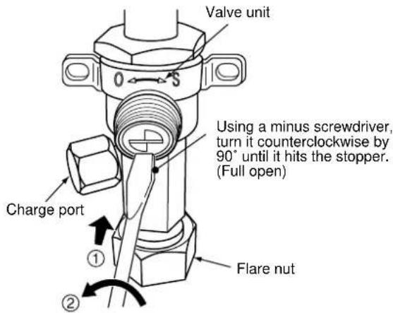
Position of grooves for driver

Closed completely Opened fully
*1. When opened fully, do not apply an excessive torque after the screwdriver hit the stopper; otherwise a trouble may be caused on the valve.
Valve handling precautions
- Open the valve stem or the handle until it strikes the stopper. It is unnecessary to apply further force.
- Securely tighten the cap with a torque wrench.
- Cap tightening torque
| Valve size | ∅9.5 | 33 to 42N•m (3.3 to 4.2kgf•m) |
| ∅15.9 | 20 to 25N•m (2.0 to 2.5kgf•m) | |
| Charge port | 14 to 18N•m (1.4 to 1.8kgf•m) | |
Heat insulation for pipe
- Apply the heat insulation to the pipework separately. (liquid, suction and discharge).
- Use thermal heat insulation which can withstand temperatures of 120^ or more.
CAUTION
- Upon completion of the pipework connections fit the piping/wiring panel and the pipe cover. Gaps between the pipes and the cover are to be filled using a suitable putty or silicone.
- If the pipework is fitted in the downward or sideways position, ensure that the base plate and side plate are closed and sealed.
- If an opening is left unsealed there is a risk of a fault due to the entering of water or dust.
WARNING
Electrical work must be performed by a qualified electrician in accordance with the installation manual.
Ensure the air conditioner uses a designated power supply.
An insufficient power supply capacity or inappropriate installation may cause a fire.
When connecting the installation wiring, be sure that all fixing terminal are securely fixed.
Ensure earthling practice is correctly performed.
Grounding is necessary, if earthling practice is incomplete an electric shock maybe caused.
CAUTION
The installation fuse must be used for the power supply line of this outdoor unit.
Incorrect/incomplete wiring might cause an electrical fire or smoke.
Prepare the exclusive power supply for the outdoor unit.
Ensure an electrical leakage breaker is fitted. This is to prevent the risk of electric shock.
To Disconnect the Appliance from Main Power Supply.
This appliance must be connected to a main power supply by means of a switch with a contact separation of at least 3 mm.
REQUIREMENT
- Perform wiring of the power supply in conformance with the regulations of the local authorities.
- For wiring of the power supply in the indoor unit, refer to the Installation Manual of the relevant indoor unit.
- Never connect 220–240V to the terminal block (U1, U2, U3, U4). (Fault will be caused.)
- Arrange the electrical wiring so that they do not come into contact with high-temperature parts of the pipework; this is to prevent the risk of insulation melting and causing a possible accident.
- After connecting wires to the terminal block, secure wiring with cable clamp.
• Install control wiring and refrigerant piping within the same line. - Do not turn on power of the indoor unit until vacuuming of the refrigerant pipe has finished.
- For cabling of the power supply of the indoor units cabling between indoor and outdoor units, refer to the Installation Manual of the indoor unit.
Connection of power supply wire with control wire
Insert power supply wire and control wire after removing knockout of the piping/wiring panel at front side of the outdoor unit.
The knockout piping and the wiring hole are also provided to the front surface, the right side, and the rear side.
Knockout for power supply

Knockout for control wiring and refrigerant piping
Note :
- Be sure to separate the power supply wires and each control wire.
- Arrange the power supply wires and each control wire so that they do not contact with the bottom surface of the outdoor unit.
- A terminal block (U3, U4 terminal blocks) for connecting an optional part “Central remote controller etc.” is provided on the inverter unit, so be careful to miswiring.
Power supply specifications
Select the power supply cabling and fuse of each outdoor unit from the following specifications.
- Ensure an earth leakage breaker is installed, failure to install, may result in electric shock.
- The installation fuse must be used for the power supply line of this outdoor unit.
- Be sure to use the appropriate type of overcurrent breaker (fuse) switch.
- Observe local regulation regarding wire size selection and installation.
3-core cable in conformance with Design 60245 IEC 66.
Do not connect the units looping via the terminal blocks (L, N).
| Power supply | MCY-MAP###HT series | 1N~ 50Hz 220V-240V |
| MCY-MAP###HT2D series | 1N~ 60Hz 220V |
| Outdoor unit capacity type | Wire size* | Maxim running current | Installation fuse |
| 0401 type | 6 mm2, Max. 28 m | 25A | 32A |
| 0501 type | 6 mm2, Max. 25 m | 28A | 32A |
| 0601 type | 6 mm2, Max. 22 m | 31A | 40A |
* Design 60245 IEC66
(Connection example)

flowchart
graph TD
    A["Outdoor unit"] --> B["Over current breaker (fuse) switch"]
    B --> C["Earth leakage breaker"]
    C --> D["Outdoor unit power supply"]
    E["L N"] --> B
    F["Earth"] --> B
    G["Ground Symbol"] --> B
Connection of power supply
■Power supply wire
- Connect the power supply cables and earthling wire to the power supply terminal block. Tighten the screws on the terminal block and secure the cables with the cord clamp. (Do not apply tension to the connecting section of the terminal block.)

For Indoor unit power supply (The outdoor unit has a separate power supply.)
| Model\Item | Power supply wiring | |
| Wire size | ||
| All models of indoor units | 2.0 mm ^2 Max. 20m | 3.5 mm ^2 Max. 50m |
Note)
• Power supply cord specification : Cable 3-core 2.5 mm², inconformity with Design 60245 IEC57.
- The connecting length indicated in the table represents the length from the pull box to the outdoor unit when the indoor units are connected in parallel for power, as shown in the illustration below. A voltage drop of no more than 2% is also assumed. If the connecting length will exceed the length indicated in the table, select the wire thickness in accordance with indoor wiring standards.
• Determine the wire size for indoor unit according to the number of connected indoor units downstream.

flowchart
graph LR
    A["Indoor unit"] --> B["Main switch"]
    B --> C["Earth leakage breaker"]
    C --> D["Pull box"]
    D --> E["Ground"]
    style A fill:#f9f,stroke:#333
    style B fill:#ccf,stroke:#333
    style C fill:#cfc,stroke:#333
    style D fill:#fcc,stroke:#333
    style E fill:#ffc,stroke:#333
Connection of PMV Kit

flowchart
graph LR
    A["PMV Kit"] --> B["Connection cable"]
    B --> C["CN82 connector"]
    C --> D["Pulse motor valve (Indoor unit side)"]
    D --> E["PMV"]
    C --> F["Indoor control P.C. board"]
    C --> G["Connector conversion cable (MMK-AP**2H (High Wall) does not use a this conversion cable)"]
    G --> H["Indoor unit"]
For details of the PMV Kit, refer to the Installation Manual.
Design of control wiring
- All control wiring is 2-core and non-polarity wire.
- Ensure use of shielded wiring in the following cases to prevent noise issues.
- Indoor-indoor / outdoor-indoor control wiring, Central control wiring.

flowchart
graph TD
    A["Central control device U1 U2 U3 U4"] --> B["Mini-SMMS"]
    B --> C["S-MMS (Super modular multi system)"]
    D["Outdoor unit U3 U4 U1 U2"] --> E["L1"]
    E --> F["Table-3"]
    G["Indoor unit U1 U2 A B"] --> H["L2 L3"]
    H --> I["L6"]
    J["Remote controller"] --> K["Table-1"]
    K --> L["L5"]
    L --> M["Table-2"]
    N["Remote controller"] --> O["L6"]
    P["Remote controller"] --> Q["L7"]
    Q --> R["Table-1"]
    S["Remote controller"] --> T["L6"]
    U["Remote controller"] --> V["L7"]
    W["Remote controller"] --> X["L6"]
    Y["Remote controller"] --> Z["L7"]
    style A fill:#f9f,stroke:#333
    style D fill:#f9f,stroke:#333
    style G fill:#f9f,stroke:#333
    style J fill:#f9f,stroke:#333
    style P fill:#f9f,stroke:#333
    style B fill:#ccf,stroke:#333
    style C fill:#ccf,stroke:#333
    style E fill:#ccf,stroke:#333
    style F fill:#ccf,stroke:#333
    style H fill:#ccf,stroke:#333
    style I fill:#ccf,stroke:#333
    style K fill:#ccf,stroke:#333
    style L fill:#ccf,stroke:#333
    style M fill:#ccf,stroke:#333
    style N fill:#ccf,stroke:#333
    style O fill:#ccf,stroke:#333
    style Q fill:#ccf,stroke:#333
    style R fill:#ccf,stroke:#333
Table-1 Control wiring between indoor and outdoor units (L1, L2, L3), Central control wiring (L4)
| Wiring | 2-core, non-polarity |
| Type | Shield wire |
| SizeLength *1 | 1.25 mm^2 : Up to 1000 m2.0 mm^2 : Up to 2000 m |
Table-2 Control wiring between outdoor units (L5) (S-MMS)
| Wiring | 2-core, non-polarity |
| Type | Shield wire |
| Size | 1.25 mm^2 to 2.0 mm^2 |
| Length | Up to 100 m (L5) |
Note *1 : Total of control wiring length for all refrigerant circuits ( L1 + L2 + L3 + L4 )
Table-3 Remote controller wiring (L6, L7)
| Wire | 2-core |
| Size | 0.5 mm ^2 to 2.0 mm ^2 |
| Length | Up to 500 m ( L6 + L7 )Up to 400m with of wireless remote controller in group control.Up to 200m total length of control wiring between indoor units ( L6 ) |
- Group Control through a Remote Controller
Group control of multiple indoor units (8 units) through a single remote controller
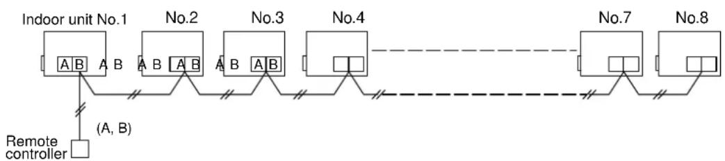
flowchart
graph LR
    A["Indoor unit No.1"] -->|A B| B["Remote controller"]
    B -->|(A, B)| C["No.2"]
    C -->|A B| D["No.3"]
    D -->|A B| E["No.4"]
    E --> F["No.7"]
    F --> G["No.8"]
    style A fill:#f9f,stroke:#333
    style C fill:#f9f,stroke:#333
    style D fill:#f9f,stroke:#333
    style E fill:#f9f,stroke:#333
    style F fill:#f9f,stroke:#333
    style G fill:#f9f,stroke:#333
Design of control wiring
- Connect each wire for controlling as shown below.
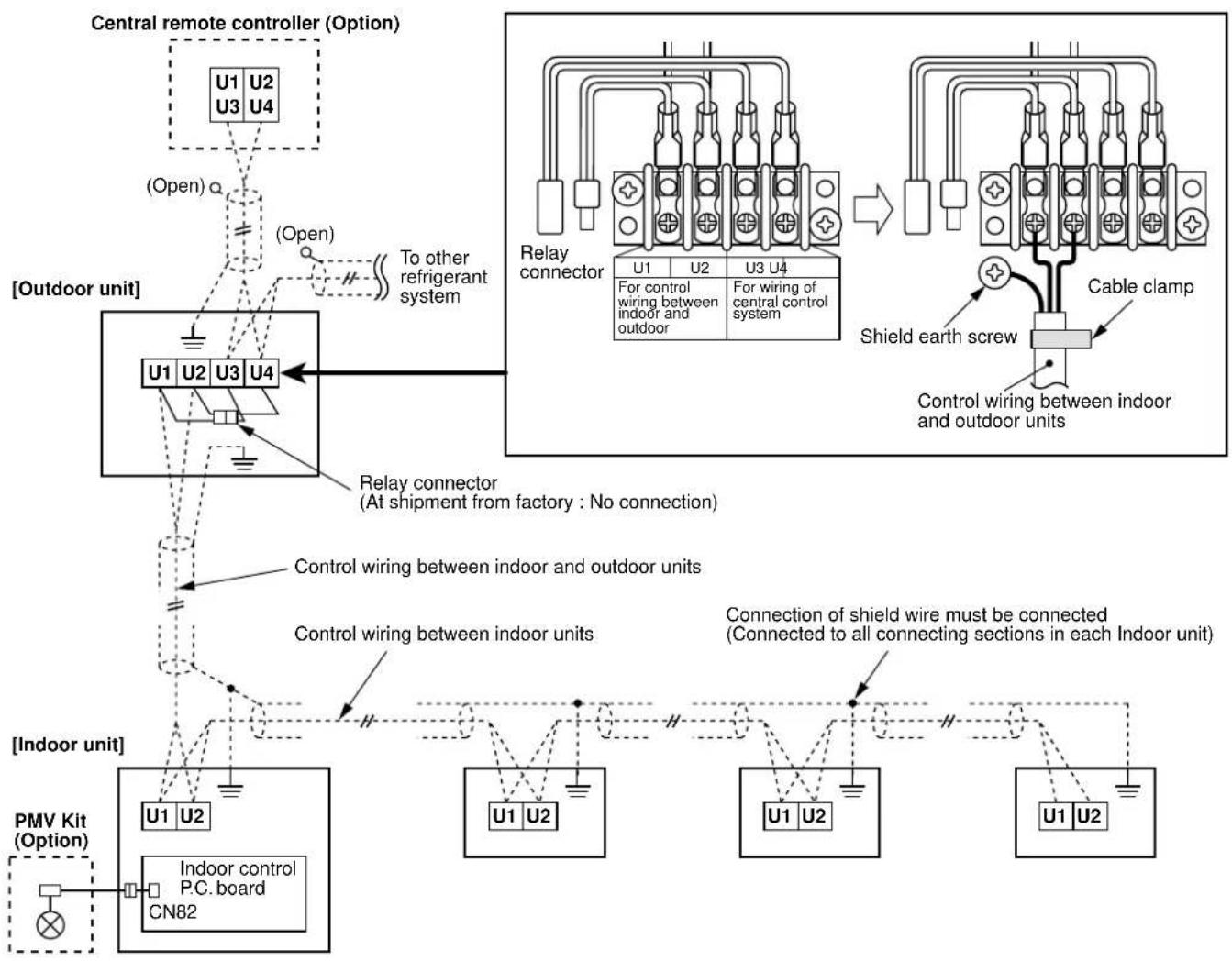
flowchart
graph TD
    A["Central remote controller (Option)"] --> B["[Outdoor unit"]]
    B --> C["Relay connector (At shipment from factory : No connection)"]
    C --> D["Control wiring between indoor and outdoor units"]
    D --> E["PMV Kit (Option)"]
    E --> F["Indoor control P.C. board CN82"]
    F --> G["Cable clamp"]
    G --> H["Shield earth screw"]
    H --> I["Cable clamp"]
    I --> J["Connection of shield wire must be connected (Connected to all connecting sections in each Indoor unit)"]
    style A fill:#f9f,stroke:#333
    style B fill:#ccf,stroke:#333
    style C fill:#cfc,stroke:#333
    style D fill:#fcc,stroke:#333
    style E fill:#cff,stroke:#333
    style F fill:#ffc,stroke:#333
    style G fill:#fcf,stroke:#333
    style H fill:#cff,stroke:#333
    style I fill:#fcf,stroke:#333
    style J fill:#cff,stroke:#333
- Wire specification, quantity, size of crossover wiring and remote controller wiring
| Name Q'ty | Size | Specification | |||
| Up to 500m Up | to 1000m 1000 to 2000m | ||||
| Control wiring(indoor-indoor / indoor-outdoor / outdoor-indoor control wiring, central control wiring) | 2 cores 1.25mm ^2 2.0mm ^2 Shield wire | ||||
| Remote controller wiring 2 cores 0.5 to 2.0mm ^2 | — | — | — | ||
- The crossover wiring and central control wiring use 2-core non-polarity transmission wires. Use 2-core shield wires to prevent noise trouble. In this case, close (connect) the end of shield wires, and perform the functional grounding for the end of the shield wires which are connected to both indoor and outdoor units.
For the shield wires which are connected between the central remote controller and the outdoor unit, perform the functional grounding at only one end of central control wiring.
- Use 2-core and non-polarity wire for remote controller. (A, B terminals)
Use 2-core and non-polarity wire for wiring of group control. (A, B terminals)
■Example of system wiring design

flowchart
graph TD
    A["Outdoor power supply"] --> B["MCY-MAP###HT series: 1N~50Hz, 220-240V"]
    A --> C["MCY-MAP###HT2D series: 1N~60Hz, 220V"]
    D["Central remote controller power supply"] --> E["1N~50Hz, 220-240V"]
    D --> F["1N~60Hz, 220V"]
    G["Earth"] --> H["U1 U2 U3 U4 LN"]
    H --> I["Relay connector (As shipment from factory: No connection)"]
    J["Outdoor unit"] --> K["U2U1 U3 U4LN"]
    L["Indoor unit"] --> M["U2U1 A B"]
    N["PMV Kit (Option)"] --> O["Indoor control P.C. board CN82"]
    P["Remote controller [Group control"]] --> Q["U2U1 A B"]
    R["Ground"] --> S["A B"]
    T["Ground"] --> U["A B"]
    V["Ground"] --> W["A B"]
    X["Ground"] --> Y["A B"]
    Z["Ground"] --> AA["A B"]
    AB["Ground"] --> AC["A B"]
    AD["Ground"] --> AE["A B"]
CAUTION
- Keep the refrigerant piping system and the indoor-indoor/indoor-outdoor control wiring systems together.
- When running power supplies and control wires parallel to each other, run them through separate conduits or maintain a suitable distance between them.
(Current capacity of power wires: 10A or less for 300mm, 50A or less for 500mm)
5 INSTALLATION OF OUTDOOR UNIT
When using the outdoor unit under the following conditions, it is necessary to set up DIP switch on the outdoor unit interface P.C. board.
CAUTION
When anyone of the following condition is applied, set up DIP switch.
- When using PMV Kit in the Mini-SMMS system
- When using the indoor unit under high humidity condition
[Reference]
Indoor side: 27°C dry bulb temperature
24°C wet bulb temperature
Operation time 4 hours or more.
Setup method
- Turn on DIP switch [SW08] on the interface P.C. board of the outdoor unit.
![Outdoor unit interface P.C. board SW11 SW12 SW13 SW14 ON ON ON ON 1 2 3 4 1 2 3 4 1 2 3 4 1 2 3 4 SW06 SW07 SW09SW08SW10 ON ON ON ON 1 2 3 4 1 2 3 4 11 2 3 4 1 2 3 4 Switch [SW08]](/content/2026/05/1038534/images/cba2667b5a9efb06d2ec7e27e28da80053673ea86e1eba57b8eb43aa3d5e4e6a.jpg)
In this air conditioner, it is necessary to set up the indoor address before starting the operation. Set up the address in the following procedure.
CAUTION
- Set up the address after the wiring work has been completed.
- Be sure to turn on the power in order of indoor unit → outdoor unit. If turning on the power in the reverse order, a check code [E19] is displayed. When a check code is displayed, turn on the power again.
- It requires a maximum of 10 minutes (Usually, approx. 5 minutes) to automatically set-up an address for 1 system.
- To set up an address automatically, the set-up of the outdoor unit needs to be completed. (Address setup cannot be performed by power-ON only.)
- To set up an address, the air conditioner does not need to be in operation.
- Manual address setup is also available besides automatic setup. Automatic address : Setup from SW15 on the interface P.C. board of the outdoor unit Manual address : Setup from the wired remote controller * It is temporarily necessary to set-up the indoor unit as a 1:1 using a wired remote controller.
Automatic Address Setup
Without central control : To the address setup procedure 1
With central control : To the address setup procedure 2
(However, go to the procedure 1 when the central control is performed in a single refrigerant system.)
| (Example) | In case of central control in a single refrigerant system | In case of central control over refrigerant system |
| Address setup procedure | To procedure 1 | To procedure 2 |
| Wire systematic diagram | 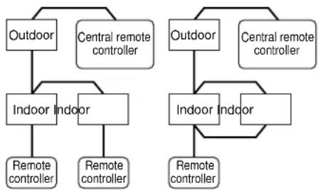 |  |
Address setup procedure 1
① Turn on power of indoor/outdoor units.
(In order of indoor → Outdoor)
② After approx. 1 minute, check that U. 1. L08 (U. 1. flash) is displayed in 7-segment display section on the interface P.C. board of the outdoor unit.
③ Push SW15 and start setup the automatic address.
(Max. 10 minutes for 1 line (Usually, approx. 5 minutes))
④ When the count 1 Auto 2 Auto 3 is displayed in 7-segment display section, and it changes from
U. 1. --- (U. 1. flash) to
U. 1. --- (U. 1. light), the setup finished.
⑤ When perform a central control, connect a relay connector between [U1U2] of the outdoor unit and [U3U4] terminals.

REQUIREMENT
- When a group control is performed over multiple refrigerant systems, be sure to turn on the power supplies to all of the indoor units connected, so that the address set-up can be completed correctly.
- If turning on the power for each refrigerant system to set up the addresses, a header indoor unit must be set for each system. Therefore, an alarm code "L03" (Duplicated header indoor units) will be displayed during in operation after the address setup has been completed. In this case, change the group address using the wired remote controller so that only one header indoor unit is set-up.
| (Example) | Group control over multiple refrigerant system |
| Wire systematic diagram | 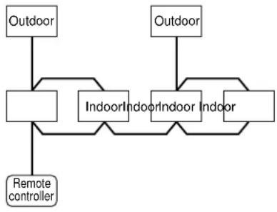 |
Address setup procedure 2
① Using SW13 and 14 on the interface P.C. board on the outdoor unit in each system, set up the system address for each system. (At shipment the address is set to 1 from the factory)
Note) Be careful not to duplicate with any other refrigerant systems or other line (system) addresses.
Line (System) address switch on outdoor interface P.C. board (

○: Switch ON, × : Switch OFF)
: Is not used for setup of line address. (Do not change setup.)
② Check that the relay connectors between [U1U2] and [U3U4] terminals are come out in all outdoor units to which the central control is connected. (At shipment from factory: No connection of connector)
③ Turn on power of indoor/outdoor. (In order of indoor → outdoor)
④ After approx. 1 minute, check that 7-segment display is U.1.L08 (U.1. flash) on the interface P.C. board.
⑤ Push SW15 and start setup the automatic address. (Max. 10 minutes for 1 line (Usually, approx. 5 minutes))
⑥ When the count Auto 1 → Auto 2 → Auto 3 is displayed in 7-segment display section, and it changes from U. 1. - - - (U. 1. flash) to U. 1. - - - (U. 1. light), the setup finished.
⑦ Procedure ④ to ⑥ are repeated in other refrigerant systems.

⑧ When address setup has finished in all the systems, turn off SW30-2 on the interface P.C. boards of the lines connected to the identical central control except a line with least line address number.
(Terminator resistors of the wires in the central control line of indoor/outdoor are unified.)
⑨ Connect the relay connector between [U1U2] and [U3U4] terminals of the outdoor unit for each refrigerant line.
⑩ Then set up the central control address.
(For the central control address setup, refer to the Installation manual of the central control devices.)

Switch setup
(Example in case of central control over refrigerant system)
Outdoor side (Manual setup)
* Manual setup is necessary for column of which letter color is reversed.
| Outdoor interfaceP.C. board | Outdoor unit | Outdoor unit | Outdoor unit | Setup at shipment from factory |
| SW13, 14(Line address) | 1 | 2 | 3 | 1 |
| SW30-2(Terminator resistor of indoor/outdoor communication line/central control communication line) | ON | OFF after address setup | OFF after address setup | ON |
| Relay connector | Short after address setup | Short after address setup | Short after address setup | Open |

flowchart
graph TD
    A["Central remote controller"] --> B["U3 U4 U3 U4"]
    B --> C["U1 U2"]
    C --> D["Relay connector"]
    D --> E["U1 U2"]
    E --> F["A B"]
    F --> G["Remote controller"]
    H["Outdoor unit"] --> I["U3 U4"]
    I --> J["U1 U2"]
    J --> K["Relay connector"]
    K --> L["U1 U2"]
    L --> M["A B"]
    M --> N["Remote controller"]
    O["Outdoor unit"] --> P["U3 U4"]
    P --> Q["U1 U2"]
    Q --> R["Relay connector"]
    R --> S["U1 U2"]
    S --> T["A B"]
    T --> U["Remote controller"]
    V["Individual"] --> W["U1 U2"]
    W --> X["A B"]
    X --> Y["Remote controller"]
    Z["Group"] --> AA["U1 U2"]
    AA --> AB["A B"]
    AB --> AC["Remote controller"]
    AD["Outdoor unit"] --> AE["U3 U4"]
    AE --> AF["U1 U2"]
    AF --> AG["A B"]
    AG --> AH["Remote controller"]
| Line address | 1 | 1 | 2 | 2 | 3 |
| Indoor unit address | 1 | 2 | 1 | 2 | 1 |
| Group address | 0 | 0 | 1 | 2 | 0 |
CAUTION
For relay connector
Never connect a relay connector until address setup for all the refrigerant systems finishes; otherwise address cannot be correctly set up.
Manual address setup from remote controller
In case to decide an address of the indoor unit prior to finish of indoor electric wiring work and unpracticed outdoor electric wiring work (Manual setup from wired remote controller)
Arrange indoor unit in which address is set up and the wired remote controller to 1 : 1.
(Wiring example in 2 lines)

flowchart
graph TD
    A["Outdoor"] --> B["Line 1"]
    B --> C["Indoor"]
    C --> D["Remote controller"]
    D --> E["Header Follower"]
    E --> F["Line address → 1"]
    E --> G["Indoor address → 1"]
    E --> H["Group address → 1"]
    I["Line 2"] --> J["End"]
    style A fill:#f9f,stroke:#333
    style C fill:#ccf,stroke:#333
    style D fill:#cfc,stroke:#333
    style E fill:#fcc,stroke:#333
    style F fill:#ffc,stroke:#333
    style G fill:#cfc,stroke:#333
    style H fill:#cfc,stroke:#333
    style I fill:#fcc,stroke:#333
In the above example, under condition of no inter-unit wire of the wired remote controller, set the address after individual connecting of the wired remote controller.
(Line address) →
(Indoor address) →
(Group address) →
Group address
Individual : 0000
Header unit : 0001
Follower unit : 0002
In case of group control
Operation procedure
$$ \mathbf {1} \rightarrow \mathbf {2} \rightarrow \mathbf {3} \rightarrow \mathbf {4} \rightarrow \mathbf {5} \rightarrow \mathbf {6} \rightarrow $$
$$ 7 \rightarrow 8 \rightarrow 9 \rightarrow 1 0 \rightarrow 1 1 \text { End } $$
Turn on the power.
1 Push simultaneously + + +TEST buttons for 4 seconds or more.
LCD changes to flashing.
2 Using the setup temp. ▼ buttons, set 12 to the item code.
3 Using the timer time ▼ buttons, set up the line address.
(Match it with the line address on the interface P.C. board of the outdoor unit in the identical refrigerant system.)
4 Push SET button.
(OK when display goes on.)
5 Using the setup temp. ▼ buttons, set 13 to the item code.
6 Using the timer time ▼ buttons, set up the indoor address.
7 Push SET button.
(OK when display goes on.)
8 Using the setup temp. ▼ buttons, set 1/4 to the item code.
9 Using the timer time ⬇ buttons, set Individual = 0000, Header unit = 0001, Follower unit = 0002.
10 Push SET button.
(OK when display goes on.)
11 Push TEST button.
Setup operation finished.
(Status returns to normal stop status.)
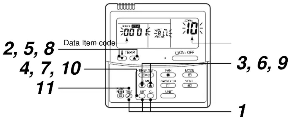
Note 1)
When setting the line address from the wired remote controller, do not use addresses 29 and 30.
The address 29 and 30 cannot be set up in the outdoor unit. Therefore if they are incorrectly set up, a check code [E04] (Indoor/outdoor communication circuit error) will be displayed.
Note 2)
When an address has been manually setup from the wired remote controller and you wish to set up a central control over the refrigeration system and setup the outdoor unit for each system using the following steps.
- Using SW13 and 14 on the interface P.C. board of the header unit in each system, set up the line address for each system.
- Turn off SW30-2 on all other interface P.C. boards on the header outdoor units that are connected to the same central control, not including the system with the least number of address lines.
(The terminator resistor of the cables in the central control system of indoor/outdoor are unified.) - Connect the relay connector between [U1U2] and [U3U4] of the header outdoor unit for each refrigerant system.
- Then set up the central control address.
(For the central control address setup, refer to the Installation manual of the central control devices.)
Confirmation of indoor address and the main unit position on the remote controller
[Confirmation of indoor unit No. and position]
- When you want to know the indoor address though position of the indoor unit itself can be recognized;
- In case of individual operation (Wired remote controller : Indoor unit = 1 : 1) or group control
[Procedure] (Operation while the air conditioner operates)
1 If it stops, push ⏻ON/OFF button.
2 Push UNIT button.
The unit NO 1-1 is displayed on the LCD. (Disappears after several seconds)
The displayed unit number indicates the line address and indoor address. (If there is other indoor unit connected to the same remote controller (Group control unit), other unit number is displayed every pushing UNIT button.)

2. When you want to know position of the indoor unit using the address
- To confirm the unit numbers in a group control;
[Procedure] (Operation while the air conditioner stops)
The indoor unit numbers in a group control are successively displayed, and the corresponding indoor fan is turned on.
1 Push VENT + TEST buttons simultaneously for 4 seconds or more.
- Unit No Fk displayed.
- The fans of all the indoor units in a group control are turned on.
2 Every pushing UNIT button, the indoor unit numbers in the group control are successively displayed.
- The firstly displayed unit number on number indicates the address of the header unit.
- Only fan of the selected indoor unit is turned on.
3 Push TEST button to finish the procedure.
All the indoor units in group control stop.

- To confirm all the unit numbers from an arbitrary wired remote controller;
[Procedure] (Operation while the air conditioner stops)
The indoor unit number and position in the same refrigerant line can be confirmed. An header unit is selected, the indoor unit numbers in the same refrigerant system are successively displayed, and then its indoor unit fan is turned on.
1 Push the timer time 📋 TEST buttons simultaneously for 4 seconds or more. Firstly, the line 1, item code HL (Address Change) is displayed. (Select outdoor unit.)
2 Using UNIT and SWING/FIX buttons, select the line address.
3 Using Ⓞ button, determine the selected line address.
- The indoor address, which is connected to the refrigerant system of the selected refrigerant system is displayed and the fan is turned on.
4 Every pushing UNIT button, the indoor unit numbers in the same refrigerant system are successively displayed.
- Only fan of the selected indoor unit operates.
[To select another line address]
5 Push ○ button to return to procedure 2.
- The indoor address of another line can be successively confirmed.
6 Push TEST button to finish the procedure.

Change of indoor address from wired remote controller
- To change the indoor address in individual operation (Wired remote controller : Indoor unit = 1 : 1) or group control (When the setup operation with automatic address has finished, this change is available.)
[Procedure] (Operation while air conditioner stops)
1 Push simultaneously + + + TEST buttons for 4 seconds or more. (The firstly displayed unit No. indicates the header indoor unit in group control.)
2 In group control, select an indoor unit No. to be changed by UNIT button.
(The fan of the selected indoor unit is turned on.)
3 Using the setup temp. ▼ / ▲ buttons, set /3 to the item code.
4 Using the timer time ▼ / ⚠ buttons, change the displayed setup data to a data which you want to change.
5 Push SET button.
6 Using the UNIT button, select the unit No. to be changed at the next time.
Repeat the procedure 4 to 6 and change the indoor address so that it is not duplicated.
7 After the above change, push UNIT button to confirm the changed contents.
8 If it is acceptable, push TEST button to finish confirmation.
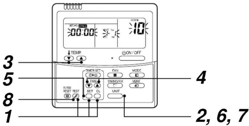
Operation procedure
1 2 3 4 5 6 7 8 End
- To change all the indoor addresses from an arbitrary wired remote controller.
(When the setup operation for automatic address has finished, this change is available.)
Contents : Using an arbitrary wired remote controller, the indoor unit address can be changed for each unit within the same refrigerant system.
* Change the address in the address check/change mode.
[Procedure] (Operation while air conditioner stops)
1 Push the timer time 📋 TEST buttons simultaneously for 4 seconds or more.
Firstly, the line 1, item code R_C (Address Change) is displayed.
2 Using UNIT / SWING/FIX buttons, select the line address.
3 Push SET button.
- The indoor address, which is connected to the refrigerant system of the selected header unit is displayed and the fan is turned on.
First the current indoor address is displayed on the setup data. (Line address is not displayed.)
4 The indoor address of the setup data moves up/down by the timer time ▼ / ▲ buttons.
Change the setup data to a new address.
5 Push SET button to determine the setup data.
6 Every pushing UNIT button, the indoor unit numbers in the same refrigerant line are successively displayed. Only fan of the selected indoor unit operates.
Repeat the procedure 4 to 6 and change all the indoor addresses so that they are not duplicated.
7 Push SET button.
(All the displays on LCD go on.)
8 Push TEST button to finish the procedure.
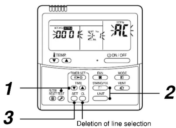
Here, if the unit No. is not called up, the header unit in this system does not exist.
Push ☐ button, and then select a line according to procedure 2.

Operation procedure
$$ 1 \rightarrow 2 \rightarrow 3 \rightarrow 4 \rightarrow 5 \rightarrow 6 \rightarrow 7 \rightarrow 8 \text { End } $$
Clearance of address (Return to status (Address undecided) at shipment from factory)
Method 1
An address is individually cleared from a wired remote controller.
"0099" is set up to line address, indoor address, and group address data from the wired remote controller.
(For the setup procedure, refer to the above-mentioned address setup from the wired remote controller.)
Method 2
Clear the indoor addresses in the same refrigerant system from the outdoor unit.
- Turn off the power of the refrigerant system to be returned to the status at shipment from factory, and change the outdoor unit to the following status.
1) Remove the relay connector between [U1U2] and [U3U4].
(If it has been already removed, leave it as it is.)
2) Turn on SW30-2 on the interface P.C. board of the outdoor unit if it is ON.
(If it has been already ON, leave it as it is.)

flowchart
graph TD
    A["Central control device"] --> B["U1 U2 U3 U4"]
    B --> C["Outdoor unit"]
    C --> D["U1 U2"]
    D --> E["Remote controller"]
    F["Outdoor unit Outdoor unit"] --> G["U1 U2"]
    G --> H["Remote controller"]
    I["Outdoor unit Outdoor unit"] --> J["U1 U2"]
    J --> K["Remote controller"]
    L["Central control device"] --> M["U1 U2 U3 U4"]
    M --> N["Outdoor unit"]
    N --> O["U1 U2"]
    O --> P["Remote controller"]
    Q["Central control device"] --> R["U1 U2 U3 U4"]
    R --> S["Outdoor unit"]
    S --> T["U1 U2"]
    T --> U["Remote controller"]
    V["Central control device"] --> W["U1 U2 U3 U4"]
    W --> X["Outdoor unit"]
    X --> Y["U1 U2"]
    Y --> Z["Remote controller"]
    AA["Central control device"] --> AB["U1 U2 U3 U4"]
    AB --> AC["Outdoor unit"]
    AC --> AD["U1 U2"]
    AD --> AE["Remote controller"]
    AF["Central control device"] --> AG["U1 U2 U3 U4"]
    AG --> AH["Outdoor unit"]
    AH --> AI["U1 U2"]
    AI --> AJ["Remote controller"]
    AK["Central control device"] --> AL["U1 U2 U3 U4"]
    AL --> AM["Outdoor unit"]
    AM --> AN["U1 U2"]
    AN --> AO["Remote controller"]
    AP["Central control device"] --> AQ["U1 U2 U3 U4"]
    AQ --> AR["Outdoor unit"]
    AR --> AS["U1 U2"]
    AS --> AT["Remote controller"]
    AU["Central control device"] --> AV["U1 U2 U3 U4"]
    AV --> AW["Outdoor unit"]
    AW --> AX["U1 U2"]
    AX --> AY["Remote controller"]
    AZ["Central control device"] --> BA["U1 U2 U3 U4"]
    BA --> BB["Outdoor unit"]
    BB --> BC["U1 U2"]
    BC --> BD["Remote controller"]
    BE["Central control device"] --> BF["U1 U2 U3 U4"]
    BF --> BG["Outdoor unit"]
    BG --> BH["U1 U2"]
    BH --> BI["Remote controller"]
    BJ["Central control device"] --> BK["U1 U2 U3 U4"]
    BK --> BL["Outdoor unit"]
    BL --> BM["U1 U2"]
    BM --> BN["Remote controller"]
        BO["Unit of which address is to be returned to the initial status"]
    BP["Unit of which address is to be returned to the initial status"]
- Turn on the indoor/outdoor power of which address is to be cleared. After approx. 1 minute, check that "U.1. - - -" is displayed, and then execute the following operation on the interface P.C. board of the outdoor unit of which address is to be cleared in the refrigerant system.
| SW01 | SW02 | SW03 | SW04 | Address which can be cleared |
| 2 | 1 | 2 | After checking that “A.d.buS” is displayed on 7-degment display, and then push SW04 for 5 seconds or more. | Line + Indoor + Group address |
| 2 | 2 | 2 | After checking that “A.d.nEt” is displayed on 7-degment display, and then push SW04 for 5 seconds or more. | Central address |
- After "A.d. c.L." has been displayed on 7-degment display, return SW01/SW02/SW03 to 1/1/1.
- When the address clearing has correctly finished, "U.1.L08" is displayed on 7-degment display after a while. If "A.d. n.G." is displayed on 7-degment display, there is a possibility which is connected with the other refrigerant system. Check again the relay connector between [U1U2] and [U3U4] terminals.
Note) Be careful that the other refrigerant system address may be also cleared if clearing operation is not correctly executed.
- After clearing of the address, set up an address again.
7 TEST OPERATION
Before test operation
Check valve of the refrigerant pipe of the outdoor unit is "OPEN".
- Using 500V-megger, check there is 1MΩ or more between the terminal block of the power supply and the earth. If the value is below 1MΩ, do not operate the air conditioner.
WARNING
• In order to protect the compressor, keep the power ON for a period of 12 hours or more before starting the air conditioner.
How to perform a test operation
In case of test operation on the wired remote controller
Check the operation of the air conditioner in usual operation by the wired remote controller.
For the procedure of the operation, refer to the attached Owner's Manual.
For a case of using a wireless remote controller, refer to the Installation Manual of the indoor unit.
A forced test operation is available in the following procedure under condition that the thermostat-OFF in the room. In a forced test operation, the test operation is cleared after operation for 60 minutes and then returns to the usual operation in order to prevent a serial operation.
Note) Do not use the forced test operation for cases other than the test operation because it applies an excessive load to the air conditioner.
In case of wired remote controller

| Procedure | Operation | |
| 1 | When pushing TEST button for 4 seconds or more, [TEST] is displayed on the display part and the mode changes to test operation mode. ([TEST] is displayed on the display part during test operation.) |  |
| 2 | Push ON/OFF button. | |
| 3 | Using MODE button, change the operation mode to [COOL] or [HEAT].Do not drive the air conditioner with a mode other than [COOL] or [HEAT].The temperature cannot be adjusted during test operation.An error is detected as usual. | 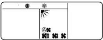 |
| 4 | After the test operation has finished, push ON/OFF button to stop the operation. (Display is same to that in procedure 1.) | |
| 5 | Push TEST button to clear the test operation mode. ([TEST] in the display part disappears and the status changes to the usual stop status.) |  |
In case of test operation on the interface P.C. board of the outdoor unit
This air conditioner has a function which executes a test operation by operation of the switches on the interface P.C. board of the outdoor unit.
This function is classified into “Individual test operation” which performs a test operation individually in each indoor unit and “Collective test operation” which performs a test operation for all the connected indoor units.
[Individual test operation]
| Procedure | Operation | 7-segment display | ||
| Start operation | 1 | Set operation mode on wired remote controller of the indoor unit which is operated with test mode to [COOL] or [HEAT]. (When it is not set up, operate the air conditioner with the current operation mode.) | [A][U1] | [B][ ] |
| 2 | Set the rotary switch SW01 on the interface P.C. board of the outdoor unit to [16], and match SW02 and SW03 to the address of the indoor unit to be operated with test mode. | [A][ ]↓Address display of the corresponding indoor unit | [B][ ] | |
| 3 | Push SW04 for 10 seconds or more.• Operation mode changes to the operation mode of wired remote controller of the corresponding indoor unit.• Temperature cannot be adjusted during “Test operation”.• Error is detected as usual.• Test operation is not performed 3 minutes after power was turned on or operation has stopped. | [A][ ]↓Address display of the corresponding indoor unit | [B][ ]↓[FF] is displayed for 5 seconds. | |
| Stop operation | 1 | Return the rotary switches on the interface P.C. board of the outdoor unit, SW01 = [1], SW02 = [1], SW03 = [1]. | [A][U1] | [B][ ] |
[Collective test operation]
| Procedure | Operation | 7-segment display | ||
| Start operation | 1 | Set the rotary switches of interface P.C. board of the outdoor unit;All cooling operation: SW01 = [2], SW02 = [5], SW03 = [1]All heating operation: SW01 = [2], SW02 = [6], SW03 = [1] | [A][C][H] | [B][ ][ ] |
| 2 | Push SW04 for 2 seconds or more.Temperature cannot be adjusted during “Test operation”.Error is detected as usual.Test operation is not performed 3 minutes after power was turned on or operation has stopped. | [A][C][H] | [B][ -C ][ -H ] | |
| Stop operation | 1 | Return the rotary switches on the interface P.C. board of the outdoor unit, SW01 = [1], SW02 = [1], SW03 = [1]. | [A][U1] | [B][ ] |

flowchart
graph TD
    A["Interface P.C. board"] --> B["7-segment display [A"]]
    B --> C["7-segment display [B"]]
    C --> D["Switch Switch"]
    C --> E["Rotary Switch"]
    style A fill:#f9f,stroke:#333
    style B fill:#ccf,stroke:#333
    style C fill:#cfc,stroke:#333
    style D fill:#fcc,stroke:#333
    style E fill:#cff,stroke:#333
In addition to the check code on the remote controller of the indoor unit, a trouble of the outdoor unit can be diagnosed by 7-segment display of the control P.C. board of the outdoor unit. Make good use of this function for various checks. After check, return each bit of Dip switch to OFF position.
■Segment display and check code
| Rotary switch setup value | Displayed contents | LED |  | ||
| SW01 SW02 SW03 | |||||
| 1 | 1 | 1 | Check code of outdoor unit | A | Outdoor unit No. (U1 only) |
| B | Check code display* | ||||
* However, when there is an auxiliary code, the check code (for 3 seconds) and the auxiliary code (for 1 second) are alternately displayed.
Check Code (Outdoor 7-segment display [B])
Displayed when SW01: 1, SW02: 1, SW03: 1
| Check codeOutdoor 7-segment display | Auxiliary code | Check code name |
| E06 | Number of indoor unit which received normally | Decrease of number of indoor units |
| E07 | — | Indoor/Outdoor communication circuit error |
| E08 | Duplicated indoor addresses | Duplication of indoor addresses |
| E12 | 01: Communication between indoor and outdoor02: Communication between outdoor units | Automatic address start error |
| E15 | — | Indoor is nothing during automatic addressing |
| E16 | 00: Capacity over 01~: No. of connected units | Capacity over / Number of connected indoor units |
| E19 | 00: Header is nothing02: Two or more header units | Number of header outdoor units error |
| E20 | 01: Other system outdoor connected02: Other system indoor connected | Other refrigerant system connected during automatic addressing |
| E31 | IPDU quantity information | IPDU communication error |
| F04 | — | TD1 sensor error |
| F06 | — | TE1 sensor error |
| F07 | — | TL sensor error |
| F08 | — | TO sensor error |
| F12 | 01: TS1 sensor error | TS1 sensor error |
| F13 | 01: Compressor 1 | TH sensor error |
| F15 | — | Outdoor temp. sensor miswiring (TE, TL) |
| F16 | — | Outdoor pressure sensor miswiring (Pd, Ps) |
| F23 | — | Ps sensor error |
| F24 | — | Pd sensor error |
| F31 | — | Outdoor EEPROM error |
| H01 | 01: Compressor 1 | Compressor breakdown |
| H02 | 01: Compressor 1 | Magnet switch errorOvercurrent relay operationCompressor trouble (Lock) |
| H03 | 01: Compressor 1 | Current detective circuit system error |
| H04 | — | Compressor 1 case thermo operation |
| H06 | — | Low-pressure protective operation |
| L04 | — | Outdoor line address duplicated |
| L06 | Number of indoor units with priority | Duplication of indoor units with priority |
| L08 | — | Indoor group/Address unset |
| L10 | — | Outdoor capacity unset |
| L18 | Detected indoor address | Flow selector unit error |
| L29 | IPDU quantity information | IPDU quantity error |
| L30 | Detected indoor address | External interlock of indoor unit |
| L31 | — | Extended I/C error |
| P03 | — | Discharge temp TD1 error |
| P04 | 01: Compressor 1 | High-pressure SW system operation |
| P07 | 01: Compressor 1 | Heat sink overheat error |
| P10 | Detected indoor address | Indoor overflow error |
| P13 | — | Outdoor liquid back detection error |
| P15 | 01: TS condition 02: TD condition | Gas leak detection |
| P19 | Detected outdoor unit number | 4-way valve inverse error |
| P20 | — | High-pressure protective operation |
| P22 | * A : Fan motor circuit error* d : Fan motor lock | Outdoor fan IPDU error |
| P26 | 01: Compressor 1 | IGBT short protection error |
| P29 | 01: Compressor 1 | Compressor position detective circuit system error |
□ Zubehör
natural_image
Line drawing of a dual air conditioning unit with fan-shaped ventilation units (no text or symbols)Platzbedarf
[Standardinstallation]
- Einzelgerät
![TOSHIBA MCY-MAP0501HT2D - [Standardinstallation] - 1](/content/2026/05/1038534/images/e1553b6f19da1afb0a6881d8196c9bdbf7c744abfd1da3c08d87dd28e9b7184e.jpg)
[Standardinstallation]
![TOSHIBA MCY-MAP0501HT2D - [Standardinstallation] - 1](/content/2026/05/1038534/images/b8a56afb8746e55ea8c1e11a407871c497d03ae602137b6732ddaa55df47dbfc.jpg)
natural_image
Technical line drawing of a pipe fitting and a rectangular component (no text or symbols)natural_image
Technical line drawing of a mechanical clamp or bracket assembly (no text or symbols)Bedienung
$$ \mathbf {1} \rightarrow \mathbf {2} \rightarrow \mathbf {3} \rightarrow $$
$$ 4 \rightarrow 5 \rightarrow 6 \text { Ende } $$
Bedienung
1 → 2 → 3 → 4 → 5 → 6 → 7 → 8 Ende
- ADOPTION OF NEW REFRIGERANT
- UTILISATION DU NOUVEAU REFRIGERANT
- SOMMAIRE
- INHALT
- SAFETY CAUTION
- WARNING
- CAUTION
- Required tools and cautions on handling
- Explanation of symbols
- SELECTION OF INSTALLATION PLACE
- Obtain permission from the customer to install the unit in a location that satisfies the following requirements :
- Avoid installing in the following places.
- AInstallation space
- Installation place
- Necessary space for installation
- Obstacle at rear side
- [Upper side is free]
- [Obstacle also at the upper side]
- Obstacle at front side
- Obstacles at both front and rear sides
- [Standard installation]
- Serial installation at front and rear sides
- Installation of outdoor unit
- Refrigerant piping connection
- TAKE NOTICE THESE IMPORTANT 4 POINTS BELOW FOR PIPING WORK
- For reference
- Knockout of pipe cover
- Knockout procedure
- How to remove the front panel
- Pipe forming/End positioning
- Flaring
- NO GOODOK
- Tightening of connecting part
- REQUIREMENT
- • Coupling size of brazed pipe
- Selection of pipe materials and size
- - Selection of pipe material
- - Capacity code of indoor and outdoor units
- Minimum wall thickness for R410A application
- Selection of refrigerant piping
- Allowable length/height difference of refrigerant piping
- Outdoor unit
- Allowable value Piping section
- Allowable length/height difference of refrigerant piping for quiet places (with PMV Kit)
- Note)
- Airtight test
- Leaked position check
- Air purge
- Addition of refrigerant
- Calculating the amount of additional refrigerant required
- Example : (0501 type)
- Additional charge amount R (kg)
- Charging of refrigerant
- Entry of refrigerant charge amount
- REFRIGERANT PIPING
- Full opening of the valve
- How to open the ball valve at gas side
- Valve handling precautions
- Heat insulation for pipe
- Connection of power supply wire with control wire
- Note :
- Power supply specifications
- Connection of power supply
- ■Power supply wire
- For Indoor unit power supply (The outdoor unit has a separate power supply.)
- Connection of PMV Kit
- Design of control wiring
- - Group Control through a Remote Controller
- ■Example of system wiring design
- INSTALLATION OF OUTDOOR UNIT
- [Reference]
- Setup method
- Automatic Address Setup
- Without central control : To the address setup procedure 1
- With central control : To the address setup procedure 2
- Address setup procedure 1
- Address setup procedure 2
- Switch setup
- Outdoor side (Manual setup)
- Manual address setup from remote controller
- Group address
- Operation procedure
- Turn on the power.
- Note 1)
- Note 2)
- Confirmation of indoor address and the main unit position on the remote controller
- [Confirmation of indoor unit No. and position]
- When you want to know position of the indoor unit using the address
- Change of indoor address from wired remote controller
- Clearance of address (Return to status (Address undecided) at shipment from factory)
- Method 1
- Method 2
- TEST OPERATION
- Before test operation
- How to perform a test operation
- In case of wired remote controller
- In case of test operation on the interface P.C. board of the outdoor unit
- Check Code (Outdoor 7-segment display [B])
- □ Zubehör
- Platzbedarf
- [Standardinstallation]
Brand : TOSHIBA
Model : MCY-MAP0501HT2D
Category : Air conditioner